KR101351896B1 - Anode For Cable Type Secondary Battery And Cable Type Secondary Battery Having The Same - Google Patents
Anode For Cable Type Secondary Battery And Cable Type Secondary Battery Having The SameDownload PDFInfo
- Publication number
- KR101351896B1 KR101351896B1KR1020100061175AKR20100061175AKR101351896B1KR 101351896 B1KR101351896 B1KR 101351896B1KR 1020100061175 AKR1020100061175 AKR 1020100061175AKR 20100061175 AKR20100061175 AKR 20100061175AKR 101351896 B1KR101351896 B1KR 101351896B1
- Authority
- KR
- South Korea
- Prior art keywords
- negative electrode
- secondary battery
- active material
- type secondary
- current collector
- Prior art date
- Legal status (The legal status is an assumption and is not a legal conclusion. Google has not performed a legal analysis and makes no representation as to the accuracy of the status listed.)
- Active
Links
Images


Classifications
- H—ELECTRICITY
- H01—ELECTRIC ELEMENTS
- H01M—PROCESSES OR MEANS, e.g. BATTERIES, FOR THE DIRECT CONVERSION OF CHEMICAL ENERGY INTO ELECTRICAL ENERGY
- H01M4/00—Electrodes
- H01M4/02—Electrodes composed of, or comprising, active material
- H01M4/04—Processes of manufacture in general
- H01M4/0438—Processes of manufacture in general by electrochemical processing
- H01M4/045—Electrochemical coating; Electrochemical impregnation
- H01M4/0452—Electrochemical coating; Electrochemical impregnation from solutions
- C—CHEMISTRY; METALLURGY
- C25—ELECTROLYTIC OR ELECTROPHORETIC PROCESSES; APPARATUS THEREFOR
- C25D—PROCESSES FOR THE ELECTROLYTIC OR ELECTROPHORETIC PRODUCTION OF COATINGS; ELECTROFORMING; APPARATUS THEREFOR
- C25D3/00—Electroplating: Baths therefor
- C25D3/02—Electroplating: Baths therefor from solutions
- C25D3/30—Electroplating: Baths therefor from solutions of tin
- C—CHEMISTRY; METALLURGY
- C25—ELECTROLYTIC OR ELECTROPHORETIC PROCESSES; APPARATUS THEREFOR
- C25D—PROCESSES FOR THE ELECTROLYTIC OR ELECTROPHORETIC PRODUCTION OF COATINGS; ELECTROFORMING; APPARATUS THEREFOR
- C25D7/00—Electroplating characterised by the article coated
- C25D7/06—Wires; Strips; Foils
- C25D7/0607—Wires
- H—ELECTRICITY
- H01—ELECTRIC ELEMENTS
- H01M—PROCESSES OR MEANS, e.g. BATTERIES, FOR THE DIRECT CONVERSION OF CHEMICAL ENERGY INTO ELECTRICAL ENERGY
- H01M10/00—Secondary cells; Manufacture thereof
- H01M10/04—Construction or manufacture in general
- H01M10/0436—Small-sized flat cells or batteries for portable equipment
- H—ELECTRICITY
- H01—ELECTRIC ELEMENTS
- H01M—PROCESSES OR MEANS, e.g. BATTERIES, FOR THE DIRECT CONVERSION OF CHEMICAL ENERGY INTO ELECTRICAL ENERGY
- H01M10/00—Secondary cells; Manufacture thereof
- H01M10/05—Accumulators with non-aqueous electrolyte
- H01M10/052—Li-accumulators
- H01M10/0525—Rocking-chair batteries, i.e. batteries with lithium insertion or intercalation in both electrodes; Lithium-ion batteries
- H—ELECTRICITY
- H01—ELECTRIC ELEMENTS
- H01M—PROCESSES OR MEANS, e.g. BATTERIES, FOR THE DIRECT CONVERSION OF CHEMICAL ENERGY INTO ELECTRICAL ENERGY
- H01M10/00—Secondary cells; Manufacture thereof
- H01M10/05—Accumulators with non-aqueous electrolyte
- H01M10/058—Construction or manufacture
- H—ELECTRICITY
- H01—ELECTRIC ELEMENTS
- H01M—PROCESSES OR MEANS, e.g. BATTERIES, FOR THE DIRECT CONVERSION OF CHEMICAL ENERGY INTO ELECTRICAL ENERGY
- H01M4/00—Electrodes
- H01M4/02—Electrodes composed of, or comprising, active material
- H01M4/13—Electrodes for accumulators with non-aqueous electrolyte, e.g. for lithium-accumulators; Processes of manufacture thereof
- H01M4/134—Electrodes based on metals, Si or alloys
- H—ELECTRICITY
- H01—ELECTRIC ELEMENTS
- H01M—PROCESSES OR MEANS, e.g. BATTERIES, FOR THE DIRECT CONVERSION OF CHEMICAL ENERGY INTO ELECTRICAL ENERGY
- H01M4/00—Electrodes
- H01M4/02—Electrodes composed of, or comprising, active material
- H01M4/64—Carriers or collectors
- H01M4/66—Selection of materials
- H01M4/661—Metal or alloys, e.g. alloy coatings
- H—ELECTRICITY
- H01—ELECTRIC ELEMENTS
- H01M—PROCESSES OR MEANS, e.g. BATTERIES, FOR THE DIRECT CONVERSION OF CHEMICAL ENERGY INTO ELECTRICAL ENERGY
- H01M4/00—Electrodes
- H01M4/02—Electrodes composed of, or comprising, active material
- H01M4/64—Carriers or collectors
- H01M4/70—Carriers or collectors characterised by shape or form
- H01M4/75—Wires, rods or strips
- H—ELECTRICITY
- H01—ELECTRIC ELEMENTS
- H01M—PROCESSES OR MEANS, e.g. BATTERIES, FOR THE DIRECT CONVERSION OF CHEMICAL ENERGY INTO ELECTRICAL ENERGY
- H01M4/00—Electrodes
- H01M4/02—Electrodes composed of, or comprising, active material
- H01M4/64—Carriers or collectors
- H01M4/70—Carriers or collectors characterised by shape or form
- H01M4/78—Shapes other than plane or cylindrical, e.g. helical
- H—ELECTRICITY
- H01—ELECTRIC ELEMENTS
- H01M—PROCESSES OR MEANS, e.g. BATTERIES, FOR THE DIRECT CONVERSION OF CHEMICAL ENERGY INTO ELECTRICAL ENERGY
- H01M4/00—Electrodes
- H01M4/02—Electrodes composed of, or comprising, active material
- H01M4/04—Processes of manufacture in general
- H01M4/0438—Processes of manufacture in general by electrochemical processing
- H01M4/044—Activating, forming or electrochemical attack of the supporting material
- H01M4/0442—Anodisation, Oxidation
- H—ELECTRICITY
- H01—ELECTRIC ELEMENTS
- H01M—PROCESSES OR MEANS, e.g. BATTERIES, FOR THE DIRECT CONVERSION OF CHEMICAL ENERGY INTO ELECTRICAL ENERGY
- H01M4/00—Electrodes
- H01M4/02—Electrodes composed of, or comprising, active material
- H01M4/64—Carriers or collectors
- H01M4/66—Selection of materials
- H01M4/665—Composites
- H01M4/667—Composites in the form of layers, e.g. coatings
- Y—GENERAL TAGGING OF NEW TECHNOLOGICAL DEVELOPMENTS; GENERAL TAGGING OF CROSS-SECTIONAL TECHNOLOGIES SPANNING OVER SEVERAL SECTIONS OF THE IPC; TECHNICAL SUBJECTS COVERED BY FORMER USPC CROSS-REFERENCE ART COLLECTIONS [XRACs] AND DIGESTS
- Y02—TECHNOLOGIES OR APPLICATIONS FOR MITIGATION OR ADAPTATION AGAINST CLIMATE CHANGE
- Y02E—REDUCTION OF GREENHOUSE GAS [GHG] EMISSIONS, RELATED TO ENERGY GENERATION, TRANSMISSION OR DISTRIBUTION
- Y02E60/00—Enabling technologies; Technologies with a potential or indirect contribution to GHG emissions mitigation
- Y02E60/10—Energy storage using batteries
- Y—GENERAL TAGGING OF NEW TECHNOLOGICAL DEVELOPMENTS; GENERAL TAGGING OF CROSS-SECTIONAL TECHNOLOGIES SPANNING OVER SEVERAL SECTIONS OF THE IPC; TECHNICAL SUBJECTS COVERED BY FORMER USPC CROSS-REFERENCE ART COLLECTIONS [XRACs] AND DIGESTS
- Y02—TECHNOLOGIES OR APPLICATIONS FOR MITIGATION OR ADAPTATION AGAINST CLIMATE CHANGE
- Y02P—CLIMATE CHANGE MITIGATION TECHNOLOGIES IN THE PRODUCTION OR PROCESSING OF GOODS
- Y02P70/00—Climate change mitigation technologies in the production process for final industrial or consumer products
- Y02P70/50—Manufacturing or production processes characterised by the final manufactured product
Landscapes
- Chemical & Material Sciences (AREA)
- Chemical Kinetics & Catalysis (AREA)
- Electrochemistry (AREA)
- Engineering & Computer Science (AREA)
- General Chemical & Material Sciences (AREA)
- Materials Engineering (AREA)
- Manufacturing & Machinery (AREA)
- Metallurgy (AREA)
- Organic Chemistry (AREA)
- Cell Electrode Carriers And Collectors (AREA)
- Secondary Cells (AREA)
- Battery Electrode And Active Subsutance (AREA)
Abstract
Translated fromKoreanDescription
Translated fromKorean본 발명은 케이블형 이차전지에 적합한 음극 및 이를 구비하는 케이블형 이차전지에 관한 것이다.The present invention relates to a negative electrode suitable for a cable type secondary battery and a cable type secondary battery having the same.
이차 전지는 외부의 전기 에너지를 화학 에너지의 형태로 바꾸어 저장해 두었다가 필요할 때에 전기를 만들어 내는 장치를 말한다. 여러 번 충전할 수 있다는 뜻으로 "충전식 전지"(rechargeable battery)라는 명칭도 쓰인다. 흔히 쓰이는 이차전지로는 납 축전지, 니켈 카드뮴 전지(NiCd), 니켈 수소 축전지(NiMH), 리튬 이온 전지(Li-ion), 리튬 이온 폴리머 전지(Li-ion polymer)가 있다. 이차 전지는 한 번 쓰고 버리는 일차 전지에 비해 경제적인 이점과 환경적인 이점을 모두 제공한다.A secondary battery is a device that converts external electrical energy into a form of chemical energy, stores it, and generates electricity when it is needed. The term "rechargeable battery" also means that the battery can be recharged several times. Common secondary batteries include lead acid batteries, NiCd batteries, NiMH batteries, Li-ion batteries, and Li-ion polymer batteries. Secondary batteries provide both economic and environmental advantages over single-use primary batteries.
이차 전지는 현재 낮은 전력을 사용하는 곳에 쓰인다. 이를테면 자동차의 시동을 돕는 기기, 휴대용 장치, 도구, 무정전 전원 장치를 들 수 있다. 최근 무선통신 기술의 발전은 휴대용 장치의 대중화를 주도하고 있으며, 종래의 많은 종류의 장치들을 무선화하는 경향도 있어, 이차전지에 대한 수요가 폭발하고 있다. 또한, 환경오염 등의 방지 측면에서 하이브리드 자동차, 전기 자동차가 실용화되고 있는데, 이들 차세대 자동차들은 이차전지를 사용하여 값과 무게를 줄이고 수명을 늘리는 기술을 채용하고 있다.Secondary cells are currently used for low power applications. Such as a device that assists the starting of a vehicle, a portable device, a tool, and an uninterruptible power supply. Background Art [0002] Recent developments in wireless communication technology have led to the popularization of portable devices and the tendency to wirelessize many types of conventional devices, and demand for secondary batteries is exploding. In addition, hybrid vehicles and electric vehicles are being put to practical use in terms of prevention of environmental pollution, and these next generation vehicles employ secondary battery technology to reduce the value and weight and increase the life span.
일반적으로 이차전지는 원통형, 각형 또는 파우치형의 전지가 대부분이다. 이는 이차전지는 음극, 양극 및 분리막으로 구성된 전극조립체를 원통형 또는 각형의 금속캔이나 알루미늄 라미네이트 시트의 파우치형 케이스 내부에 장착하고, 상기 전극 조립체에 전해질을 주입시켜 제조하기 때문이다. 따라서, 이차전지 장착을 위한 일정한 공간이 필수적으로 요구되므로, 이러한 이차전지의 원통형, 각형 또는 파우치형의 형태는 다양한 형태의 휴대용 장치의 개발에 대한 제약으로 작용하게 되는 문제점이 있다. 이에, 다양한 형태가 가능한 신규한 형태의 이차전지가 요구되며, 가요성이 우수한 단면적 직경에 대하여 길이의 비가 매우 큰 전지인 선형전지가 제안되었다.Generally, a secondary battery is a cylindrical, square, or pouch type battery. This is because the secondary battery is manufactured by inserting an electrode assembly composed of a cathode, an anode, and a separator into a pouch-shaped case of a cylindrical or rectangular metal can or an aluminum laminate sheet, and injecting an electrolyte into the electrode assembly. Therefore, since a certain space for mounting the secondary battery is indispensably required, there is a problem that the cylindrical shape, the square shape, or the pouch shape of the secondary battery acts as a constraint on the development of various types of portable devices. Accordingly, there is a need for a new type of secondary battery capable of various forms, and a linear battery having a very large ratio of lengths to a cross-sectional diameter having excellent flexibility has been proposed.
그러나, 이러한 가요성이 요구되는 케이블형 이차전지는 구조적 특성상 이차전지가 꺾이는 경우와 같은 외부의 물리적인 충격이 빈번하게 발생하게 되므로 사용에 의한 단선의 우려가 높으며, 또한 Si 또는 Sn과 같은 음극활물질을 사용하는 경우에 반복된 충방전에 의한 전극의 팽창과 수축에 의하여 활물질이 탈리되게 되는데 이러한 경우에 케이블형 이차전지는 물리적인 충격이 빈번하게 발생하게 되므로 일반적인 이차전지의 경우보다 전지성능 저하가 심화되는 문제점이 있다.However, the cable type secondary battery which requires such flexibility has a high possibility of disconnection due to the external physical shock such as when the secondary battery is bent due to its structural characteristics, and there is a high possibility of disconnection due to use, and also a negative electrode active material such as Si or Sn. In the case of using the active material is detached by the expansion and contraction of the electrode due to repeated charging and discharging, in this case, since the cable-type secondary battery has a physical impact frequently occurs, the battery performance deterioration than that of the general secondary battery There is a deepening problem.
따라서 본 발명이 해결하고자 하는 과제는, 전기화학적 반응성이 우수하고, 전지 내부의 스트레스 및 압력에 대한 완충작용이 가능한 다공성 구조를 갖는 리튬 이차전지용 음극을 제공하는 것이다.Accordingly, an object of the present invention is to provide a lithium secondary battery negative electrode having a porous structure which is excellent in electrochemical reactivity and capable of buffering stress and pressure inside the battery.
상기 과제를 해결하기 위하여, 소정 형상의 수평 단면을 가지며 길이 방향으로 연장되는 집전체인 코어부 및 그 코어부의 외면을 음극 활물질로 감싸며 코팅된 다공성 쉘부를 구비하는 케이블형 이차전지용 음극을 제공한다.In order to solve the above problems, there is provided a negative electrode for a cable-type secondary battery having a horizontal cross-section of a predetermined shape and a core portion that is a collector extending in the longitudinal direction and the outer surface of the core portion wrapped with a negative electrode active material and having a coated porous shell portion.
이러한 음극 활물질은 Si, Sn, Li, Zn, Mg, Cd, Ce, Ni, Fe 및 이들의 산화물 중에서 선택된 1 종의 화합물 또는 2종 이상의 혼합물을 포함하는 것을 특징으로 하는 케이블형 이차전지용 음극인 것을 사용할 수 있다.The negative electrode active material is Si, Sn, Li, Zn, Mg, Cd, Ce, Ni, Fe and one of the compounds selected from the oxide or a mixture of two or more kinds of a negative electrode for a cable type secondary battery characterized in that Can be used.
집전체는 스테인리스스틸, 알루미늄, 티탄, 은, 팔라듐, 니켈, 구리; 또는 스테인리스스틸의 표면에 티탄, 은, 팔라듐, 니켈, 구리로 표면처리한 것을 것일 수 있으며, 또한 와이어 형태의 집전체는 고분자 코어부 및 상기 고분자 코어부 표면에 형성된 금속 코팅층을 구비하는 것일 수 있다.The current collector is stainless steel, aluminum, titanium, silver, palladium, nickel, copper; Alternatively, the surface of the stainless steel may be a surface treated with titanium, silver, palladium, nickel, and copper, and the current collector in the form of a wire may include a polymer core part and a metal coating layer formed on the surface of the polymer core part. .
이러한 고분자 코어부는 폴리아세틸렌 (polyacetylene), 폴리아닐린 (polyaniline), 폴리피롤 (polypyrrole), 폴리티오펜 (polythiophene), 폴리설퍼니트리드(poly sulfur nitride), 폴리에틸렌(polyetylene, PE), 폴리프로필렌(polypropylene, PP), 폴리염화비닐(polyvinyl chloride, PVC), 폴리비닐알코올(polyvinyl alcoho, PVA), 아크릴계 고분자(polyacrylate), 및 폴리테트라플루오로에틸렌(polytetrafluoroethylene, PTFE) 등을 사용할 수 있고, 이러한 금속 코팅층은 은, 팔라듐, 니켈 및 구리중에서 선택된 1종 또는 2종 이상의 혼합물인 금속 등을 사용할 수 있다.The polymer core portion is polyacetylene, polyaniline, polypyrrole, polythiophene, poly sulfur nitride, polyethylene, PE, polypropylene, PP ), Polyvinyl chloride (PVC), polyvinyl alcohol (polyvinyl alcoho (PVA), acrylic polymer (polyacrylate), and polytetrafluoroethylene (polytetrafluoroethylene, PTFE) and the like can be used, such a metal coating layer is , Palladium, nickel and copper The metal etc. which are 1 type (s) or mixture of 2 or more types selected from among these can be used.
또한, 본 발명의 다공성 쉘부의 기공크기는 10 내지 150 ㎛이고, 다공성 쉘부의 기공도는 60 내지 95 %이며, 다공성 쉘부의 표면적은 8×10⁴ 내지 5×105 cm2/g일 수 있다.In addition, the pore size of the porous shell portion of the present invention is 10 to 150 ㎛, the porosity of the porous shell portion is 60 to 95%, the surface area of the porous shell portion may be 8 × 10⁴ to 5 × 105 cm2 / g. .
본 발명의 케이블형 이차전지용 음극은, (S1) 음극 활물질 수용액을 준비하는 단계; 및 (S2) 상기 음극 활물질 수용액에, 소정 형상의 수평 단면을 가지며 길이 방향으로 연장되는 집전체인 코어부를 담근 후에 전기를 통전시켜 집전체인 코어부의 외면에 다공성 쉘부를 형성하는 단계를 포함한다.The negative electrode for a cable type secondary battery of the present invention comprises the steps of preparing an aqueous solution of a negative electrode active material (S1); And (S2) forming a porous shell portion on the outer surface of the core portion, which is the current collector, by energizing the core after immersing the core portion having a horizontal cross-section having a predetermined shape and extending in the longitudinal direction in the negative electrode active material solution.
또한, 본 발명의 다공성 음극은 리튬 이차전지에 사용될 수 있으며, 특히 케이블형 이차전지에 적합하다.In addition, the porous negative electrode of the present invention can be used in a lithium secondary battery, it is particularly suitable for cable type secondary battery.
본 발명의 음극은 다공성의 기공구조로 인하여 완충작용이 가능하므로 이차전지가 꺾이는 경우와 같은 외부의 물리적인 충격에 강하므로 단선을 방지한다. 또한, Si나 Sn와 같은 음극활물질을 사용하는 경우에는 충방전 시에 발생하는 부피팽창과 같은 전지 내부의 스트레스 및 압력에 대한 완충작용이 가능하여 전지의 변형을 방지하고 안정성의 확보가 가능하다.Since the negative electrode of the present invention is capable of buffering due to the porous pore structure, it is resistant to external physical shock such as when the secondary battery is bent, thereby preventing disconnection. In addition, in the case of using a negative electrode active material such as Si or Sn, it is possible to buffer against stress and pressure inside the battery such as volume expansion generated during charging and discharging, thereby preventing deformation of the battery and securing stability.
그리고, 본 발명의 음극은 음극활물질로 이루어진 다공성 쉘부를 구비하므로 높은 표면적을 가지고, 따라서 전해질 특히 고체전해질과의 접촉면적이 증가되어 리튬 이온의 이동성이 향상되므로 이온전도도가 우수하므로 전지성능이 뛰어나다.In addition, the negative electrode of the present invention has a high surface area because it has a porous shell made of a negative electrode active material, and thus the contact area with an electrolyte, especially a solid electrolyte, is increased, and thus the mobility of lithium ions is improved.
이러한 특성으로 인하여 본 발명의 음극은 케이블형 이차전지에 적합하다.Due to these characteristics, the negative electrode of the present invention is suitable for a cable type secondary battery.
본 명세서에 첨부되는 다음의 도면들은 본 발명의 바람직한 실시예를 예시하는 것이며, 전술한 발명의 내용과 함께 본 발명의 기술사상을 더욱 이해시키는 역할을 하는 것이므로, 본 발명은 그러한 도면에 기재된 사항에만 한정되어 해석되어서는 아니된다.
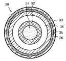
도 1은 전도성 코어부를 구비하는 다공성 음극의 단면도이다.
도 2는 고분자 코어부 및 상기 고분자 코어부 표면에 형성된 금속 코팅층을 구비하는 다공성 음극의 단면도이다.
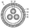
도 3은 일 실시예에 따른 다공성 음극을 구비하는 케이블형 이차전지의 단면도이다.
도 4는 일 실시예에 따른 다공성 음극을 구비하는 케이블형 이차전지의 단면도이다.
도 5는 일 실시예에 따른 다공성 음극을 구비하는 케이블형 이차전지의 단면도이다.
도 6은 일 실시예에 따른 다공성 음극을 구비하는 케이블형 이차전지의 단면도이다.
도 7은 일 실시예에 따른 다공성 음극을 구비하는 케이블형 이차전지의 단면도이다.
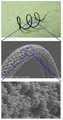
도 8는 실시예 1에 따른 다공성 음극의 SEM 사진이다.
도 9는 비교예 1에 따른 음극을 구비하는 반쪽전지의 전지성능을 나타낸 그래프이다.
도 10은 실시예 1에 따른 음극을 구비하는 반쪽전지의 전지성능을 나타낸 그래프이다.BRIEF DESCRIPTION OF THE DRAWINGS The accompanying drawings, which are incorporated in and constitute a part of the specification, illustrate exemplary embodiments of the invention and, together with the description of the invention, It should not be construed as limited.
1 is a cross-sectional view of a porous cathode having a conductive core portion.
2 is a cross-sectional view of a porous cathode having a polymer core part and a metal coating layer formed on a surface of the polymer core part.
3 is a cross-sectional view of a cable type secondary battery having a porous negative electrode according to an embodiment.
4 is a cross-sectional view of a cable type secondary battery having a porous negative electrode according to an embodiment.
5 is a cross-sectional view of a cable-type secondary battery having a porous negative electrode according to an embodiment.
6 is a cross-sectional view of a cable type secondary battery having a porous negative electrode according to an embodiment.
7 is a cross-sectional view of a cable-type secondary battery having a porous negative electrode according to an embodiment.
8 is a SEM photograph of the porous cathode according to Example 1;
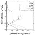
9 is a graph showing the battery performance of a half cell having a negative electrode according to Comparative Example 1.
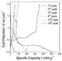
10 is a graph showing battery performance of a half cell having a negative electrode according to Example 1;
이하, 본 발명을 도면을 참조하여 상세히 설명하기로 한다. 본 명세서 및 청구범위에 사용된 용어나 단어는 통상적이거나 사전적인 의미로 한정해서 해석되어서는 아니 되며, 발명자는 그 자신의 발명을 가장 최선의 방법으로 설명하기 위해 용어의 개념을 적절하게 정의할 수 있다는 원칙에 입각하여 본 발명의 기술적 사상에 부합하는 의미와 개념으로 해석되어야만 한다.Hereinafter, the present invention will be described in detail with reference to the drawings. The terms and words used in the present specification and claims should not be construed as limited to ordinary or dictionary terms and the inventor may appropriately define the concept of the term in order to best describe its invention It should be construed as meaning and concept consistent with the technical idea of the present invention.
도 1 및 도 2에는 본 발명에 따른 다공성 음극(10, 20)의 일 실시예가 개략적으로 도시되어 있다. 하지만, 이하 본 명세서에 기재된 실시예와 도면에 도시된 구성은 본 발명의 가장 바람직한 일 실시예에 불과할 뿐이고 본 발명의 기술적 사상을 모두 대변하는 것은 아니므로, 본 출원시점에 있어서 이들을 대체할 수 있는 다양한 균등물과 변형예들이 있을 수 있음을 이해하여야 한다.1 and 2 schematically show one embodiment of the
본 발명의 음극은 소정 형상의 수평 단면을 가지며 길이 방향으로 연장되는 집전체인 코어부(11) 및 그 코어부의 외면을 음극 활물질로 감싸며 코팅된 다공성 쉘부(12)를 구비한다. 여기서 소정의 형상이라 함은 특별히 형상을 제한하지 않는다는 것으로, 본 발명의 본질을 훼손하지 않는 어떠한 형상도 가능하다는 의미이다. 이러한 집전체(11)의 수평단면은 원형 또는 다각형일 수 있는데, 원형 구조는 기하학적으로 완전한 대칭형의 원형과 비대칭형의 타원형 구조이다. 다각형 구조는 특별히 제한되는 것은 아니고, 이러한 다각형 구조의 비제한적인 예로는 삼각형, 사각형, 오각형 또는 육각형일 수 있다.The negative electrode of the present invention has a horizontal cross-section having a predetermined shape and includes a
집전체(11)의 표면에 음극 활물질(12)을 전기도금법 또는 양극산화 처리방법 등을 이용하여 다공성의 음극활물질층을 형성한다. 이러한 음극 활물질은 Si, Sn, Li, Zn, Mg, Cd, Ce, Ni, Fe 및 이들의 산화물 중에서 선택된 1 종의 화합물 또는 2종 이상의 혼합물을 포함하는 것을 특징으로 하는 케이블형 이차전지용 음극인 것을 사용할 수 있다.The negative electrode
전기도금법을 이용하여 집전체의 표면에 활물질층을 형성하는 경우에는, 수소기체가 발생하게 되는 데 이러한 수소의 발생량 및 발생하는 수소 기포의 크기를 조절하여 원하는 기공크기를 가지는 3차원적인 기공구조의 활물질층을 형성할 수 있다.When the active material layer is formed on the surface of the current collector by using the electroplating method, hydrogen gas is generated. By controlling the amount of generated hydrogen and the size of the generated hydrogen bubbles, a three-dimensional pore structure having a desired pore size An active material layer can be formed.
또한, 양극산화 처리방법을 이용하여 집전체의 표면에 금속 산화물 계열의 활물질층을 형성할 수 있다. 이와 같은 경우에, 양극산화 조건 하에서 발생하는 산소 기체량 및 기포 크기를 조절하여 1차원적인 채널(channel) 형태를 가지는 기공구조의 금속 산화물로 이루어진 활물질층을 형성할 수 있다.Further, the metal oxide-based active material layer can be formed on the surface of the current collector by using the anodic oxidation treatment method. In this case, an active material layer composed of a metal oxide having a pore structure having a one-dimensional channel shape can be formed by controlling the amount of oxygen gas and the size of bubbles generated under an anodizing condition.
이러한 다공성 쉘부의 기공크기는 10 내지 150 ㎛일 수 있다. 또한, 이러한 다공성 쉘부의 기공도는 60 내지 95 %일 수 있으며, 다공성 쉘부의 표면적은 8×10⁴ 내지 5×105 cm2/g인 것을 사용할 수 있다.The pore size of the porous shell portion may be 10 to 150 ㎛. In addition, the porosity of the porous shell portion may be 60 to 95%, and the surface area of the porous shell portion may be 8 × 10⁴ to 5 × 105 cm2 / g.
본 발명에 따라 소정 형상의 수평 단면을 가지며 길이 방향으로 연장되는 집전체인 코어부(11) 및 그 코어부의 외면을 음극 활물질로 감싸며 코팅된 다공성 쉘부(12)를 구비하는 음극(10)을 제조하는 방법은 다음과 같다.According to the present invention, a
먼저, 음극 활물질 수용액을 준비한다(S1 단계).First, an aqueous negative active material solution is prepared (step S1).
음극 활물질 수용액은 산성의 수용액에 음극 활물질을 용해시켜 준비하는데, 주로 음극 활물질이 산성염의 형태로 존재하는 전구체를 사용한다. 음극 활물질로는 Si, Sn, Li, Zn, Mg, Cd, Ce, Ni 및 Fe 등을 사용할 수 있으며, 특히 Si 또는 Sn을 사용하는 것이 바람직하다.The negative electrode active material solution is prepared by dissolving the negative electrode active material in an acidic aqueous solution, and a precursor in which the negative electrode active material is present in the form of an acid salt is used. Si, Sn, Li, Zn, Mg, Cd, Ce, Ni and Fe, etc. can be used as a negative electrode active material, It is preferable to use Si or Sn especially.
이어서, 상기 음극 활물질 수용액에, 소정 형상의 수평 단면을 가지며 길이 방향으로 연장되는 집전체인 코어부를 담근 후에 전기를 통전시켜 집전체인 코어부의 외면에 다공성 쉘부를 형성한다(S2 단계).Subsequently, the core active material is immersed in the aqueous solution of the negative electrode active material and has a horizontal cross section having a predetermined shape and then is electrically energized to form a porous shell on the outer surface of the core part as the current collector (step S2).
음극 활물질 수용액이 담긴 비이커에 집전체인 코어부와 상대 전극으로 양극과 음극을 구성하여 전기도금 장치를 준비한다. 일정시간 동안 전기를 통전시켜 음극 활물질이 석출되어 음극 활물질층을 형성한다. 이때 집전체인 코어부에는 수소기체가 생성되면서 다공성 구조를 갖는 음극 활물질층이 형성된다.An electroplating apparatus is prepared by forming a positive electrode and a negative electrode with a core part and a counter electrode, which are current collectors, in a beaker containing an aqueous solution of a negative electrode active material. The anode is energized for a predetermined time to precipitate a negative electrode active material to form a negative electrode active material layer. At this time, while the hydrogen gas is generated in the core portion as the current collector, a negative electrode active material layer having a porous structure is formed.
이차전지는 충·방전시 반복되는 팽창 및 수축에 의해 스웰링(swelling)하게 되는데 특히 Sn 및 Si계 음극활물질을 사용하는 경우에 그 정도가 심하다. 따라서 이러한 부피 변화에 의해 활물질이 탈락되거나 열화되고, 또한 부반응을 촉발시켜 전지의 성능을 저하시키는 문제점이 있다. 그러나 본 발명의 활물질층은 다공성 구조로 되어 있어 부피변화에 대한 완충작용이 가능하여 이러한 문제점을 완화시킬 수 있다.Secondary batteries are swelled by repeated expansion and contraction during charging and discharging, especially when using Sn and Si-based negative electrode active materials. Therefore, there is a problem that the active material is dropped or deteriorated by such a volume change, and also triggers a side reaction, thereby degrading the performance of the battery. However, the active material layer of the present invention has a porous structure and can alleviate this problem by enabling a buffer action against volume change.
그리고, 다공성의 활물질층으로 인하여 전해질과 접촉하는 음극의 표면적이 증가하게 되어 리튬 이온의 이동이 빠르고 원활히 할 수 있어 전기화학반응에 유리하므로 전지의 성능의 향상을 가져온다.In addition, the surface area of the negative electrode contacting the electrolyte is increased due to the porous active material layer, so that the movement of lithium ions can be quickly and smoothly, which is advantageous for the electrochemical reaction, thereby improving the performance of the battery.
본 발명의 와이어 형태의 집전체(11)는 서로 독립적으로 각각 스테인리스스틸, 알루미늄, 니켈, 티탄, 소성탄소, 구리 및 스테인리스스틸의 표면에 카본, 니켈, 티탄, 은으로 표면처리한 것, 알루미늄-카드뮴합금에 의하여 제조되는 것, 폴리아세틸렌 (polyacetylene), 폴리아닐린 (polyaniline), 폴리피롤 (polypyrrole), 폴리티오펜 (polythiophene) 또는 폴리설퍼니트리드(poly sulfur nitride)인 것일 수 있다. 특히 케이블형 이차전지의 가요성 확보를 위해서 상기 와이어 형태의 집전체는 고분자 코어부(21) 및 상기 고분자 코어부 표면에 형성된 금속 코팅층(22)을 구비하는 것이 바람직하다.The
이러한 고분자 코어부(21)는 폴리아세틸렌 (polyacetylene), 폴리아닐린 (polyaniline), 폴리피롤 (polypyrrole), 폴리티오펜 (polythiophene), 폴리설퍼니트리드(poly sulfur nitride), 폴리에틸렌(polyetylene, PE), 폴리프로필렌(polypropylene, PP), 폴리염화비닐(polyvinyl chloride, PVC), 폴리비닐알코올(polyvinyl alcoho, PVA), 아크릴계 고분자(polyacrylate), 및 폴리테트라플루오로에틸렌(polytetrafluoroethylene, PTFE) 등을 사용할 수 있고, 이러한 금속 코팅층(22)은 은, 팔라듐, 니켈 및 구리중에서 선택된 1종 또는 2종 이상의 혼합물인 금속 등을 사용할 수 있다.The
전술한 본 발명의 음극은 양극과 결합하여 전극구조체를 이루고 전해질을 사용하여 리튬 이차전지로 제조된다. 전극 구조체를 이루는 양극 및 전해질은 리튬 이차전지 제조에 통상적으로 사용되던 것들이 모두 사용될 수 있다.The negative electrode of the present invention described above forms an electrode structure by combining with the positive electrode and is manufactured as a lithium secondary battery using an electrolyte. As the positive electrode and the electrolyte constituting the electrode structure, all of those conventionally used in manufacturing a lithium secondary battery may be used.
구체적인 예로, 양극 활물질로는 리튬함유 전이금속 산화물이 바람직하게 사용될 수 있으며, 예를 들면 LiCoO2, LiNiO2, LiMnO2, LiMn2O4, Li(NiaCobMnc)O2(0<a<1, 0<b<1, 0<c<1, a+b+c=1), LiNi1-yCoyO2, LiCo1-yMnyO2, LiNi1-yMnyO2(O≤y<1), Li(NiaCobMnc)O4(0<a<2, 0<b<2, 0<c<2, a+b+c=2), LiMn2-zNizO4, LiMn2-zCozO4(0<z<2), LiCoPO4 및 LiFePO4로 이루어진 군에서 선택되는 어느 하나 또는 이들 중 2종 이상의 혼합물을 사용할 수 있다. 또한, 이러한 산화물(oxide) 외에 황화물(sulfide), 셀렌화물(selenide) 및 할로겐화물(halide) 등도 사용될 수 있다.As a specific example, a lithium-containing transition metal oxide may be preferably used as the cathode active material, for example, LiCoO2 , LiNiO2 , LiMnO2 , LiMn2 O4 , Li (Nia Cob Mnc ) O2 (0 < a <1, 0 <b <1, 0 <c <1, a + b + c = 1), LiNi1-y Coy O2 , LiCo1-y Mny O2 , LiNi1-y Mny O2 (O ≦ y <1), Li (Nia Cob Mnc ) O4 (0 <a <2, 0 <b <2, 0 <c <2, a + b + c = 2), LiMn2 Any one selected from the group consisting of-z Niz O4 , LiMn2-z Coz O4 (0 <z <2), LiCoPO4 and LiFePO4 or a mixture of two or more thereof may be used. In addition to these oxides, sulfide, selenide and halide may also be used.
전해질로는 PEO, PVdF, PVdF-HFP, PMMA, PAN 또는 PVAC를 사용한 겔형 고분자 전해질; 또는 PEO, PPO(polypropylene oxide), PEI(polyethylene imine), PES(polyethyle sulphide) 또는 PVAc(polyvinyl acetate)를 사용한 고체 전해질 등을 사용할 수 있다. 또한, 전해질은 리튬염을 더 포함할 수 있는 데, 이러한 리튬염은 LiCl, LiBr, LiI, LiClO4, LiBF4, LiB10Cl10, LiPF6, LiCF3SO3, LiCF3CO2, LiAsF6, LiSbF6, LiAlCl4, CH3SO3Li, CF3SO3Li, (CF3SO2)2NLi, 클로로보란리튬, 저급지방족카르본산리튬 및 4페닐붕산리튬 등을 사용할 수 있다.As the electrolyte, a gel type polymer electrolyte using PEO, PVdF, PVdF-HFP, PMMA, PAN or PVAC; Alternatively, a solid electrolyte using PEO, polypropylene oxide (PPO), polyethylene imine (PEI), polyethylen sulphide (PES), or polyvinyl acetate (PVAc) may be used. In addition, the electrolyte may further include a lithium salt, which lithium salt is LiCl, LiBr, LiI, LiClO4 , LiBF4 , LiB10 Cl10 , LiPF6 , LiCF3 SO3 , LiCF3 CO2 , LiAsF6 , LiSbF6 , LiAlCl4 , CH3 SO3 Li, CF3 SO3 Li, (CF3 SO2 )2 NLi, chloroborane lithium, lower aliphatic carbonate, lithium tetraphenylborate, and the like can be used.
이하에서는 본 발명의 음극을 구비하는 케이블형 이차전지의 구체적인 구조를 도 3을 참조하여 간략하게 살펴본다. 각 도면 중에서 동일 부호는 동일 또는 동등한 구성요소를 나타내고 있다.Hereinafter, a detailed structure of a cable type secondary battery having a negative electrode according to the present invention will be briefly described with reference to FIG. 3. In the drawings, the same reference numerals denote the same or equivalent components.
도 3을 참조하면, 일 실시예에 따른 케이블형 이차전지(30)는 소정 형상의 수평 단면을 가지는 집전체(31)에 음극활물질(32)이 코팅된 음극(31, 32)이 평행하게 배치된 내부전극; 상기 내부전극을 둘러싸며 충진된, 이온의 통로가 되는 전해질층(33); 상기 전해질층의 외면을 둘러싸는, 소정 형상의 수평 단면을 갖는 파이프형의 집전체(35)에 양극활물질(34)이 도포된 양극(34, 35)인 외부전극; 및 상기 외부전극의 둘레에 배치되는 보호피복(36)을 포함한다. 복수개의 내부전극 및 파이프형의 외부전극을 구비하여 접촉면적이 증가하므로 높은 전지 레이트를 갖으며, 내부전극의 개수를 조절하여 내부전극과 외부전극과의 용량 밸런스의 조절이 용이하다. 이러한 케이블형 이차전지의 양극(34, 35)은 집전체(35)에 활물질(34)이 도포되어 있는 데, 활물질을 포함하는 전극슬러리를 압출기를 통하여 집전체에 압출코팅하는 방법을 사용하여 제조하는 것이 바람직하다. 활물질이 전기도금된 음극(31, 32)을 내부전극으로 하여 내부전극의 외부를 전해질층(33)으로 코팅하거나 전해질층(33)에 내부전극을 삽입하는 공정을 통하여 제조할 수 있다. 이와 같이 내부전극과 전해질층(33)을 형성하고 그 외면에 외부전극(34, 35) 및 보호피복(36)을 형성하는 방법으로 제조할 수 있다. 또한, 전해질층(33)을 포함하는 외부전극(34, 35) 및 보호피복(36)을 형성한 후에 전해질층(33)에 내부전극을 삽입하여 제조하거나, 외부전극(20, 21) 및 보호피복(36)을 형성한 후에 내부전극을 삽입하고 전해질층(33)을 채워 넣어 제조하는 방법도 가능하다.Referring to FIG. 3, in the cable type
본 발명의 보호피복은 절연체로서 공기 중의 수분 및 외부충격에 대하여 전극을 보호하기 위해 전지의 외면에 형성한다. 보호피복으로는 통상의 고분자 수지를 사용할 수 있으며, 일례로 PVC, HDPE 또는 에폭시 수지가 사용 가능하다.The protective coating of the present invention is formed on the outer surface of the battery as an insulator to protect the electrode against moisture and external shock in the air. As the protective coating, a conventional polymer resin can be used. For example, PVC, HDPE or epoxy resin can be used.
또한, 도 3의 케이블형 이차전지와 같이 도 4, 도 5, 도 6 및 도 7의 변형된 케이블형 이차전지도 가능하다.Also, like the cable type secondary battery of FIG. 3, the modified cable type secondary batteries of FIGS. 4, 5, 6, and 7 are also possible.
도 4를 참조하면, 일 실시예에 따른 케이블형 이차전지(30)는 소정 형상의 수평 단면을 가지는 집전체(31)에 음극활물질(32)이 도포된 음극(31, 32)이 평행하게 배치된 내부전극; 상기 내부전극을 둘러싸며 충진된, 이온의 통로가 되는 전해질층(33); 상기 전해질층의 외면을 둘러싸는, 소정 형상의 수평 단면을 갖는 파이프형의 집전체(35)에 양극활물질(34)이 도포된 양극(34, 35)인 외부전극; 및 상기 외부전극의 둘레에 배치되는 보호피복(36)을 포함한다. 복수개의 내부전극 및 파이프형의 외부전극을 구비하여 접촉면적이 증가하므로 높은 전지 레이트를 갖으며, 내부전극의 개수를 조절하여 내부전극과 외부전극과의 용량 밸런스의 조절이 용이하다. 이러한 케이블형 이차전지의 양극(34, 35)은 집전체(35)에 활물질(34)이 도포되어 있는 데, 이러한 도포방법으로는 일반적인 코팅방법이 적용될 수 있으며, 구체적으로는 전기도금(electroplating) 또는 양극산화처리(anodic oxidation process) 방법이 사용가능하고, 활물질을 포함하는 전극슬러리를 압출기를 통하여 압출코팅하는 방법을 사용하여 제조하는 것이 바람직하다. 활물질이 전기도금된 음극(31, 32)을 내부전극으로 하여 내부전극의 외부를 전해질층(33)으로 코팅하거나 전해질층(33)에 내부전극을 삽입하는 공정을 통하여 제조할 수 있다. 이와 같이 내부전극과 전해질층(33)을 형성하고 그 외면에 외부전극(34, 35) 및 보호피복(36)을 형성하는 방법으로 제조할 수 있다. 또한, 전해질층(33)을 포함하는 외부전극(34, 35) 및 보호피복(36)을 형성한 후에 전해질층(33)에 내부전극을 삽입하여 제조하거나, 외부전극(34, 35) 및 보호피복(36)을 형성한 후에 내부전극을 삽입하고 전해질층(33)을 채워 넣어 제조하는 방법도 가능하다.Referring to FIG. 4, in the cable type
도 5를 참조하면, 일 실시예에 따른 케이블형 이차전지(30)는 소정 형상의 수평 단면을 가지며, 길이 방향으로 연장되고 이온의 통로가 되는 전해질층(33)이 외면에 형성된 집전체(31)에 음극활물질(32)이 전기도금된 2 이상의 음극(31, 32)이 평행하게 배치된 내부전극; 상기 내부전극을 둘러싸며 충진된 양극 활물질층(34) 및 집전체(35)를 포함하는 양극(34, 35)인 외부전극; 및 상기 외부전극의 둘레에 배치되는 보호피복(36)을 포함한다. 파이프형의 외부전극 내부에 복수개의 내부전극을 구비하여 접촉면적이 증가하므로 높은 전지 레이트를 갖는다. 또한, 내부전극의 개수를 조절하여 내부전극과 외부전극과의 용량 밸런스의 조절이 용이하고, 내부전극에 전해질층이 형성되어 있어 단락(short)을 방지할 수 있다. 이러한 케이블형 이차전지는, 제조된 음극(31, 32)을 내부전극으로 하고 내부전극의 외면을 전해질층(33)으로 코팅한다. 전해질층이 코팅된 내부전극의 외부를 활물질(34)로 코팅하거나 활물질층(34)에 내부전극을 삽입하는 공정을 통하여 제조할 수 있다. 이와 같이 내부전극과 활물질을 형성하고 그 외면에 외부전극의 집전체(35) 및 보호피복(36)을 형성하는 방법으로 제조할 수 있다. 또한, 내면에 활물질을 채운 외부전극(34, 35) 및 보호피복(36)을 형성한 후에 외부전극의 활물질에 내부전극을 삽입하여 제조하거나, 외부전극의 집전체(35) 및 보호피복(36)을 형성한 후에 내부전극을 삽입하고 활물질을 채워 넣어 제조하는 방법도 가능하다.Referring to FIG. 5, the cable type
도 6을 참조하면, 일 실시예에 따른 케이블형 이차전지(30)는 소정 형상의 수평 단면을 가지며, 길이 방향으로 연장되고 이온의 통로가 되는 제1 전해질층(33a)이 외면에 형성된 집전체에 음극 활물질이 전기도금된 1 이상의 음극(31, 32); 소정 형상의 수평 단면을 가지며, 길이 방향으로 연장되는 집전체(35)에 양극 활물질(34)이 도포된 1 이상의 양극(34, 35); 이들 음극 및 양극 모두를 평행하게 배치하고 공통으로 둘러싸며 충진된 이온의 통로가 되는 제2 전해질층(33b); 및 상기 제2 전해질층(33b)의 둘레에 배치되는 보호피복(36)을 포함하며, 추가로 양극(34, 35)에 전해질층이 형성될 수도 있다. 전극에 추가적인 전해질층을 도입하여 단락(short)의 방지가 가능하다. 복수개의 양극과 음극을 구비하여 접촉면적이 증가하므로 높은 전지 레이트를 갖는다. 또한, 음극과 양극의 수를 조절하여 전극의 용량 밸런스의 조정이 용이하다. 이러한 케이블형 이차전지는, 제조된 음극에 제1 전해질층(33a)을 코팅한 후에 음극 및 양극 전극 모두를 둘러싸도록 제2 전해질층(33b)으로 코팅하거나 제2 전해질층(33b)에 삽입하는 공정을 통하여 제조할 수 있으며, 그 후에 제2 전해질층(33b)의 외면에 보호피복(36)을 형성하는 방법으로 제조할 수 있다. 또한, 제2 전해질층(33b) 및 보호피복(36)을 형성한 후에 제2 전해질층(33b)에 음극 및 양극을 삽입하여 제조하는 방법도 가능하다.Referring to FIG. 6, the cable type
도 7을 참조하면, 일 실시예에 따른 케이블형 이차전지(30)는 소정 형상의 수평 단면을 가지며, 길이 방향으로 연장된 내부 집전체(31)에 음극활물질(32)이 전기도금된 다공성 음극(31, 32), 상기 음극에 전해질층(33)이 형성되고 다시 그 표면에 양극 활물질층(34)이 형성되고 평행하게 배치된 다수의 내부전극; 상기 내부전극을 둘러싸며 충진된 외부 집전체(35); 상기 외부 집전체(35)의 둘레에 배치되는 보호피복(36)을 포함한다. 복수개의 내부전극 및 외부 집전체를 구비하여 접촉면적이 증가하므로 높은 전지 레이트를 갖으며, 내부전극의 개수를 조절하여 전극의 용량 밸런스의 조절이 용이하다.
Referring to FIG. 7, the cable type
이하, 본 발명을 구체적으로 설명하기 위해 실시예를 들어 상세하게 설명하기로 한다. 그러나, 본 발명에 따른 실시예는 여러 가지 다른 형태로 변형될 수 있으며, 본 발명의 범위가 아래에서 상술하는 실시예에 한정되는 것으로 해석되어서는 안 된다. 본 발명의 실시예는 당업계에서 평균적인 지식을 가진 자에게 본 발명을 보다 완전하게 설명하기 위해서 제공되는 것이다.
BEST MODE FOR CARRYING OUT THE INVENTION Hereinafter, the present invention will be described in detail with reference to examples. However, the embodiments according to the present invention can be modified into various other forms, and the scope of the present invention should not be construed as being limited to the embodiments described below. The embodiments of the present invention are provided to enable those skilled in the art to more fully understand the present invention.
실시예Example
실시예 1. 와이어형 다공성 음극의 제조Example 1 Preparation of Wire-Type Porous Cathode
와이어형의 구리 집전체를 아세톤과 묽은 염산으로 세척하였다. 상기 구리 집전체를 양극으로 백금을 음극으로 구성하여 0.15M SnSO4, 1.5M H2SO4 용액에 담그었다. 이후에 3A/cm2 이상의 전류를 흘려주면서 전기도금을 하였다. 구리 집전체에 주석이 석출되어 와이어형 다공성 음극이 제조되었다.
The wire-shaped copper current collector was washed with acetone and dilute hydrochloric acid. The copper current collector was used as a positive electrode and platinum was used as a negative electrode to immerse in a 0.15 M SnSO4 , 1.5 MH2 SO4 solution. After that, electroplating was performed while flowing a current of 3 A / cm2 or more. Tin was deposited on the copper current collector to prepare a wire-type porous cathode.
비교예 1. 필름형 다공성 음극의 제조Comparative Example 1. Preparation of Film-type Porous Cathode
필름형의 구리 집전체를 아세톤과 묽은 염산으로 세척하였다. 상기 구리 집전체를 양극으로 백금을 음극으로 구성하여 0.15M SnSO4, 1.5M H2SO4 용액에 담그었다. 이후에 3A/cm2 이상의 전류를 흘려주면서 전기도금을 하였다. 구리 집전체에 주석이 석출되어 필름형 다공성 음극이 제조되었다.
The film-shaped copper current collector was washed with acetone and dilute hydrochloric acid. The copper current collector was used as a positive electrode and platinum was used as a negative electrode to immerse in 0.15M SnSO4 , 1.5MH2 SO4 solution. After that, electroplating was performed while flowing a current of 3 A / cm2 or more. Tin was deposited on the copper current collector to prepare a film-type porous cathode.
시험예 1. 다공성 음극의 기공구조의 확인Test Example 1. Confirmation of pore structure of porous cathode
실시예 1에서 제조된 다공성 음극의 SEM사진을 도 4에 나타내었다. 도 4에 따르면, 구리 집전체의 표면에 3차원의 기공의 구조를 가지는 주석으로 이루어진 음극활물질층이 형성되어 있음을 알 수 있다.
The SEM photograph of the porous negative electrode prepared in Example 1 is shown in FIG. 4. According to FIG. 4, it can be seen that a negative electrode active material layer made of tin having a three-dimensional pore structure is formed on the surface of the copper current collector.
시험예 2. 전지의 성능 측정Test Example 2 Measurement of Battery Performance
리튬 포일(foil)을 대전극/환원전극(counter/reference electrode)으로 구성하고, 측정전극(working electrode)으로는 상기 실시예 1 및 비교예 1에서 제조된 음극을 사용하여 3원 전극 전기화학 셀 형태의 비이커 셀을 만들었다.A lithium foil comprises a counter electrode / reduction electrode, and a three-electrode electrochemical cell using a cathode prepared in Example 1 and Comparative Example 1 as a working electrode. A beaker cell of the form was made.
이때 사용된 전해액은 EC/ DEC = 50/50(v/v)의 1M LiPF6이고, 시험은 Glove-box(Ar gas)에서 진행하였다. 이와 같이 제조된 전지를 사용하여 충방전 특성을 평가하여 도 9와 도 10에 각각 나타내었다.In this case, the electrolyte solution used was 1 M LiPF 6 of EC / DEC = 50/50 (v / v), and the test was performed in a Glove-box (Ar gas). Charging and discharging characteristics of the battery manufactured as described above were evaluated and shown in FIGS. 9 and 10, respectively.
충전지 0.5C의 전류밀도로 5 mV까지 정전류 충전 후 정전압으로 5mV로 일정하게 유지시켜 전류밀도가 0.005C가 되면 충전을 종료하였다.After charging a constant current to 5 mV at a current density of 0.5 C of a rechargeable battery, charging was maintained at a constant voltage of 5 mV, and when the current density reached 0.005 C, charging was completed.
방전시 0.5C의 전류밀도로 2V까지 CC모드로 방전을 완료하였다. 동일한 조건으로 충방전을 50회 반복하였다.The discharge was completed in CC mode up to 2V at a current density of 0.5C. Charging and discharging were repeated 50 times under the same conditions.
도 9와 도 10에 따르면, 와이어형의 다공성 전극을 사용한 경우가 필름형의 다공성 전극을 사용한 경우 보다 용량과 성능이 모두 우수함을 알 수 있다.9 and 10, it can be seen that the case of using the wire-type porous electrode is superior in both capacity and performance than the case of using the film-type porous electrode.
10 : 다공성 음극 11 : 집전체
12 : 음극활물질층
20 : 다공성 음극21 : 고분자 코어부
22 : 금속 코팅층23 : 음극활물질층
30 : 케이블형 이차전지31 : 내부 집전체
32 : 음극활물질층33 : 전해질층
33a : 제 1 전해질층33b: 제 2전해질층
34 : 양극 활물질층35 : 외부 집전체
36 : 보호피복10
12: cathode active material layer
20: porous cathode 21: polymer core portion
22: metal coating layer 23: negative electrode active material layer
30 cable
32: negative electrode active material layer 33: electrolyte layer
33a:
34 positive electrode
36: protective clothing
Claims (26)
Translated fromKorean상기 다공성 쉘부의 기공크기는 10 내지 150 ㎛인 케이블형 이차전지용 음극.A core having a horizontal cross section of a predetermined shape and extending in the longitudinal direction is provided with a porous shell portion coated with a negative electrode active material surrounding the outer surface of the core portion and the core portion,
The pore size of the porous shell portion 10 to 150 ㎛ negative electrode for a cable-type secondary battery.
상기 음극 활물질은 Si, Sn, Li, Zn, Mg, Cd, Ce, Ni, Fe; 및 이들의 산화물 중에서 선택된 1 종의 화합물 또는 2종 이상의 혼합물을 포함하는 것을 특징으로 하는 케이블형 이차전지용 음극.The method of claim 1,
The negative active material is Si, Sn, Li, Zn, Mg, Cd, Ce, Ni, Fe; And at least one compound selected from oxides thereof, or a mixture of two or more kinds thereof.
상기 음극 활물질은 Si, Sn 또는 이들의 혼합물인 것을 특징으로 하는 케이블형 이차전지용 음극.3. The method of claim 2,
The negative electrode active material is Si, Sn or a negative electrode for a cable type secondary battery, characterized in that a mixture thereof.
상기 집전체는 스테인리스스틸, 알루미늄, 티탄, 은, 팔라듐, 니켈, 구리; 또는 스테인리스스틸의 표면에 티탄, 은, 팔라듐, 니켈 또는 구리로 표면 처리한 것을 특징으로 하는 케이블형 이차전지용 음극.The method of claim 1,
The current collector is stainless steel, aluminum, titanium, silver, palladium, nickel, copper; Or a surface treated with titanium, silver, palladium, nickel or copper on the surface of stainless steel.
상기 집전체는 고분자 코어부 및 상기 고분자 코어부 표면에 형성된 금속 코팅층을 구비하는 것을 특징으로 하는 케이블형 이차전지용 음극.The method of claim 1,
The current collector has a polymer core portion and a metal coating layer formed on the surface of the polymer core portion negative electrode for a cable type secondary battery.
상기 고분자 코어부는 폴리아세틸렌 (polyacetylene), 폴리아닐린 (polyaniline), 폴리피롤 (polypyrrole), 폴리티오펜 (polythiophene), 폴리설퍼니트리드(poly sulfur nitride), 폴리에틸렌(polyetylene, PE), 폴리프로필렌(polypropylene, PP), 폴리염화비닐(polyvinyl chloride, PVC), 폴리비닐알코올(polyvinyl alcoho, PVA), 아크릴계 고분자(polyacrylate) 및 폴리테트라플루오로에틸렌(polytetrafluoroethylene, PTFE) 중에서 선택된 1종 화합물 또는 2종 이상의 혼합물인 고분자로 이루어진 것을 특징으로 하는 케이블형 이차전지용 음극.6. The method of claim 5,
The polymer core portion polyacetylene, polyaniline, polypyrrole, polythiophene, polysulfur nitride, poly sulfur nitride, polyethylene, polypropylene, polypropylene, PP ), Polyvinyl chloride (PVC), polyvinyl alcohol (polyvinyl alcoho (PVA), acrylic polymer (polyacrylate) and polytetrafluoroethylene (polytetrafluoroethylene, PTFE) selected from the group consisting of one or a mixture of two or more polymers Cathode for a cable-type secondary battery, characterized in that consisting of.
상기 금속 코팅층은 티탄, 은, 팔라듐, 니켈 및 구리중에서 선택된 1종 또는 2종 이상의 혼합물인 금속으로 이루어진 것을 특징으로 하는 케이블형 이차전지용 음극.6. The method of claim 5,
The metal coating layer is titanium, silver, palladium, nickel and copper A negative electrode for a cable type secondary battery, characterized in that made of a metal which is one or a mixture of two or more selected from.
상기 다공성 쉘부의 기공도는 60 내지 95 %인 것을 특징으로 하는 케이블형 이차전지용 음극.The method of claim 1,
The porosity of the porous shell portion is a negative electrode for a cable type secondary battery, characterized in that 60 to 95%.
상기 다공성 쉘부의 표면적은 8×10⁴ 내지 5×105 cm2/g인 것을 특징으로 하는 케이블형 이차전지용 음극.The method of claim 1,
The surface area of the porous shell portion is a negative electrode for a cable-type secondary battery, characterized in that 8 × 10⁴ to 5 × 105 cm2 / g.
(S2) 상기 음극 활물질 수용액에, 소정 형상의 수평 단면을 가지며 길이 방향으로 연장되는 집전체인 코어부를 담근 후에 전기를 통전시켜 집전체인 코어부의 외면에 다공성 쉘부를 형성하는 단계;를 포함하되,
상기 다공성 쉘부의 기공크기는 10 내지 150 ㎛인 케이블형 이차전지용 음극의 제조방법.(S1) preparing a negative active material solution; And
(S2) immersing the core part, which is a current collector extending in the longitudinal direction, having a horizontal cross section of a predetermined shape in the aqueous solution of the negative electrode active material, and then conducting electricity to form a porous shell part on the outer surface of the core part, which is the current collector;
The pore size of the porous shell portion 10 to 150 ㎛ method of manufacturing a negative electrode for a cable-type secondary battery.
상기 음극 활물질은 Si, Sn, Li, Zn, Mg, Cd, Ce, Ni 및 Fe; 및 이들의 산화물 중에서 선택된 1 종의 화합물 또는 2종 이상의 혼합물을 포함하는 것을 특징으로 하는 케이블형 이차전지용 음극의 제조방법.12. The method of claim 11,
The negative electrode active material is Si, Sn, Li, Zn, Mg, Cd, Ce, Ni and Fe; And a compound selected from one of these oxides, or a mixture of two or more thereof.
상기 집전체는 서로 독립적으로 각각 스테인리스스틸, 알루미늄, 티탄, 은, 팔라듐, 니켈, 구리 및 스테인리스스틸의 표면에 티탄, 은, 팔라듐, 니켈 또는 구리로 표면처리한 것을 특징으로 하는 케이블형 이차전지용 음극의 제조방법.12. The method of claim 11,
The current collectors are independently of each other, the surface of the stainless steel, aluminum, titanium, silver, palladium, nickel, copper and stainless steel surface of titanium, silver, palladium, nickel or copper surface treated with a negative electrode for a cable type secondary battery Manufacturing method.
상기 집전체는 고분자 코어부 및 상기 고분자 코어부 표면에 형성된 금속 코팅층을 구비하는 것을 특징으로 하는 케이블형 이차전지용 음극의 제조방법.12. The method of claim 11,
The current collector is a method of manufacturing a negative electrode for a cable-type secondary battery, characterized in that it comprises a polymer core portion and a metal coating layer formed on the surface of the polymer core portion.
상기 고분자 코어부는 폴리아세틸렌 (polyacetylene), 폴리아닐린 (polyaniline), 폴리피롤 (polypyrrole), 폴리티오펜 (polythiophene), 폴리설퍼니트리드(poly sulfur nitride), 폴리에틸렌(polyetylene, PE), 폴리프로필렌(polypropylene, PP), 폴리염화비닐(polyvinyl chloride, PVC), 폴리비닐알코올(polyvinyl alcoho, PVA), 아크릴계 고분자(polyacrylate) 및 폴리테트라플루오로에틸렌(polytetrafluoroethylene, PTFE) 중에서 선택된 1종 화합물 또는 2종 이상의 혼합물인 고분자로 이루어진 것을 특징으로 하는 케이블형 이차전지용 음극의 제조방법.The method of claim 14,
The polymer core portion polyacetylene, polyaniline, polypyrrole, polythiophene, polysulfur nitride, poly sulfur nitride, polyethylene, polypropylene, polypropylene, PP ), Polyvinyl chloride (PVC), polyvinyl alcohol (polyvinyl alcoho (PVA), acrylic polymer (polyacrylate) and polytetrafluoroethylene (polytetrafluoroethylene, PTFE) selected from the group consisting of one or a mixture of two or more polymers Method for producing a negative electrode for a cable-type secondary battery, characterized in that consisting of.
상기 금속 코팅층은 은, 팔라듐, 니켈 및 구리중에서 선택된 1종 또는 2종 이상의 혼합물인 금속으로 이루어진 것을 특징으로 하는 케이블형 이차전지용 음극의 제조방법.The method of claim 14,
The metal coating layer is silver, palladium, nickel and copper Method for producing a negative electrode for a cable-type secondary battery, characterized in that made of a metal which is one or a mixture of two or more selected from.
상기 내부전극을 둘러싸며 충진된, 이온의 통로가 되는 전해질층;
상기 전해질층의 외면을 둘러싸는, 소정 형상의 수평 단면을 갖는 파이프형의 집전체에 양극 활물질층이 형성된 양극인 외부전극; 및
상기 외부전극의 둘레에 배치되는 보호피복을 포함하되,
상기 다공성 쉘부의 기공크기는 10 내지 150 ㎛인 케이블형 이차전지.An inner electrode having a horizontal cross-section having a predetermined shape and having a core portion extending in the longitudinal direction and a cathode including a porous shell portion coated with an outer surface of the core portion wrapped with a negative electrode active material and having a coated porous shell portion;
An electrolyte layer which is filled around the inner electrode and becomes a passage of ions;
An external electrode which is an anode having a cathode active material layer formed on a pipe-type current collector having a horizontal cross section of a predetermined shape surrounding an outer surface of the electrolyte layer; And
Including a protective coating disposed around the outer electrode,
The pore size of the porous shell portion 10 to 150 ㎛ cable type secondary battery.
상기 내부전극을 둘러싸며 충진된, 이온의 통로가 되는 전해질층;
상기 전해질층의 외면을 둘러싸는, 양극 활물질층이 형성된 파이프형의 집전체인 양극으로 이루어진 외부전극; 및
상기 외부전극의 둘레에 배치되는 보호피복을 포함하되,
상기 다공성 쉘부의 기공크기는 10 내지 150 ㎛인 케이블형 이차전지.An inner electrode having a horizontal cross-section having a predetermined shape and having at least two negative electrodes in parallel with a core portion which is a current collector extending in a longitudinal direction, and an outer surface of the core portion having a porous shell portion coated with a negative electrode active material;
An electrolyte layer which is filled around the inner electrode and becomes a passage of ions;
An external electrode made of a positive electrode which is a pipe-type current collector having a positive electrode active material layer formed around the outer surface of the electrolyte layer; And
Including a protective coating disposed around the outer electrode,
The pore size of the porous shell portion 10 to 150 ㎛ cable type secondary battery.
상기 내부전극을 둘러싸며 충진된 양극 활물질층을 포함하는 파이프형의 집전체인 양극으로 이루어진 외부전극; 및
상기 외부전극의 둘레에 배치되는 보호피복을 포함하되,
상기 다공성 쉘부의 기공크기는 10 내지 150 ㎛인 케이블형 이차전지.2, in which an electrolyte layer serving as a passage of ions is formed on the outer surface of the shell portion of the negative electrode having a horizontal cross section having a predetermined shape and extending in the longitudinal direction, and covering the outer surface of the core portion with a negative electrode active material and covering the outer surface of the core portion with a negative electrode active material. Internal electrodes in which the above cathodes are arranged in parallel;
An external electrode made of a positive electrode which is a pipe-type current collector including a positive electrode active material layer filled around the internal electrode; And
Including a protective coating disposed around the outer electrode,
The pore size of the porous shell portion 10 to 150 ㎛ cable type secondary battery.
소정 형상의 수평 단면을 가지며 길이 방향으로 연장되는, 집전체에 양극 활물질층이 형성된 1 이상의 양극;
이들 양극 및 제1 전해질층이 형성된 음극 모두를 평행하게 배치하고 공통으로 둘러싸며 충진된 이온의 통로가 되는 제2 전해질층; 및
상기 제2 전해질층의 둘레에 배치되는 보호피복을 포함하되,
상기 다공성 쉘부의 기공크기는 10 내지 150 ㎛인 케이블형 이차전지.The first electrolyte layer serving as a passage of ions on the outer surface of the shell portion of the negative electrode having a horizontal cross section of a predetermined shape and the core portion extending in the longitudinal direction and the outer surface of the core portion wrapped with a negative electrode active material and having a coated porous shell portion At least one cathode formed;
At least one positive electrode having a horizontal cross section of a predetermined shape and extending in the longitudinal direction, the positive electrode active material layer being formed on the current collector;
A second electrolyte layer in which both of these anodes and the cathode on which the first electrolyte layer is formed are arranged in parallel and commonly surround and serve as passages of charged ions; And
Including a protective coating disposed around the second electrolyte layer,
The pore size of the porous shell portion 10 to 150 ㎛ cable type secondary battery.
양극 활물질층이 형성된 음극 모두를 평행하게 배치하고 공통으로 둘러싸며 충진된 집전체; 및
상기 충진된 집전체의 둘레에 배치되는 보호피복을 포함하되,
상기 다공성 쉘부의 기공크기는 10 내지 150 ㎛인 케이블형 이차전지.An electrolyte layer serving as a passage of ions is formed on the outer surface of the shell portion of the negative electrode having a horizontal cross section having a predetermined shape and covering the core portion extending in the longitudinal direction and the outer surface of the core portion with a negative electrode active material and having a coated porous shell portion. At least two cathodes having a cathode active material layer formed thereon;
A current collector in which all of the negative electrodes in which the positive electrode active material layer is formed are disposed in parallel and commonly surrounded and filled; And
Including a protective coating disposed around the filled current collector,
The pore size of the porous shell portion 10 to 150 ㎛ cable type secondary battery.
상기 양극 활물질층은 LiCoO2, LiNiO2, LiMn2O4, LiCoPO4, LiFePO4, LiNiMnCoO2 및 LiNi1-x-y-zCoxM1yM2zO2(M1 및 M2는 서로 독립적으로 Al, Ni, Co, Fe, Mn, V, Cr, Ti, W, Ta, Mg 및 Mo로 이루어진 군으로부터 선택된 어느 하나이고, x, y 및 z는 서로 독립적으로 산화물 조성 원소들의 원자 분율로서 0 ≤ x < 0.5, 0 ≤ y < 0.5, 0 ≤ z < 0.5, x+y+z ≤ 1임)로 이루어진 군으로부터 선택된 어느 하나의 활물질 입자 또는 이들 중 2종 이상의 혼합물인 양극 활물질로 이루어진 것을 특징으로 하는 케이블형 이차전지.23. The method according to any one of claims 18 to 22,
The cathode active material layer is LiCoO2 , LiNiO2 , LiMn2 O4 , LiCoPO4 , LiFePO4 , LiNiMnCoO2 and LiNi1-xyz Cox M1y M2z O2 (M1 and M2 are independently of each other Al, Ni, Co , Fe, Mn, V, Cr, Ti, W, Ta, Mg and Mo, and x, y and z independently of each other as the atomic fraction of the elements of the oxide composition 0 ≤ x <0.5, 0 ≤ y <0.5, 0 ≤ z <0.5, x + y + z ≤ 1), any one active material particles selected from the group consisting of a cable-type secondary battery, characterized in that made of a positive electrode active material which is a mixture of two or more thereof .
상기 전해질층, 제1 전해질층 또는 제2 전해질층은 서로 독립적으로 PEO, PVdF, PVdF-HFP, PMMA, PAN 또는 PVAC를 사용한 겔형 고분자 전해질; 또는 PEO, PPO(polypropylene oxide), PEI(polyethylene imine), PES(polyethyle sulphide) 또는 PVAc(polyvinyl acetate)를 사용한 고체 전해질; 중에서 선택된 전해질로 이루어진 것을 특징으로 하는 케이블형 이차전지.23. The method according to any one of claims 18 to 22,
The electrolyte layer, the first electrolyte layer or the second electrolyte layer is a gel polymer electrolyte using a PEO, PVdF, PVdF-HFP, PMMA, PAN or PVAC independently of each other; Or a solid electrolyte using PEO, polypropylene oxide (PPO), polyethylene imine (PEI), polyethyle sulphide (PES), or polyvinyl acetate (PVAc); Wherein the electrolyte is selected from the group consisting of a lithium salt and a lithium salt.
상기 전해질층은 리튬염을 더 포함하는 것을 특징으로 하는 케이블형 이차전지.23. The method according to any one of claims 18 to 22,
Wherein the electrolyte layer further comprises a lithium salt.
상기 리튬염은 LiCl, LiBr, LiI, LiClO4, LiBF4, LiB10Cl10, LiPF6, LiCF3SO3, LiCF3CO2, LiAsF6, LiSbF6, LiAlCl4, CH3SO3Li, CF3SO3Li, (CF3SO2)2NLi, 클로로보란리튬, 저급지방족카르본산리튬 및 4페닐붕산리튬 중에서 선택된 1종 또는 2종 이상인 것을 특징으로 하는 케이블형 이차전지.26. The method of claim 25,
The lithium salt is LiCl, LiBr, LiI, LiClO4 , LiBF4 , LiB10 Cl10 , LiPF6 , LiCF3 SO3 , LiCF3 CO2 , LiAsF6 , LiSbF6 , LiAlCl4 , CH3 SO3 Li, CF3 SO3 Li, (CF3 SO2 )2 NLi, chloroborane lithium, lower aliphatic lithium carbonate, lithium tetraphenyl carbonate, one or more selected from the group consisting of a cable type secondary battery.
Priority Applications (7)
| Application Number | Priority Date | Filing Date | Title |
|---|---|---|---|
| KR1020100061175AKR101351896B1 (en) | 2010-06-28 | 2010-06-28 | Anode For Cable Type Secondary Battery And Cable Type Secondary Battery Having The Same |
| CN201180032693.7ACN102959767B (en) | 2010-06-28 | 2011-05-18 | Negative electrode for cable-type secondary battery and cable-type secondary battery including the same |
| PCT/KR2011/003679WO2012002646A2 (en) | 2010-06-28 | 2011-05-18 | Negative electrode for a cable-type secondary battery and cable-type secondary battery having same |
| EP11801053.7AEP2587569B1 (en) | 2010-06-28 | 2011-05-18 | Negative electrode for a cable-type secondary battery and cable-type secondary battery having same |
| JP2013516495AJP5793565B2 (en) | 2010-06-28 | 2011-05-18 | Negative electrode for cable-type secondary battery and cable-type secondary battery having the same |
| US13/540,024US8785020B2 (en) | 2010-06-28 | 2012-07-02 | Anode for cable-type secondary battery and cable-type secondary battery including the anode |
| US14/298,104US9406926B2 (en) | 2010-06-28 | 2014-06-06 | Anode for cable-type secondary battery and cable-type secondary battery including the anode |
Applications Claiming Priority (1)
| Application Number | Priority Date | Filing Date | Title |
|---|---|---|---|
| KR1020100061175AKR101351896B1 (en) | 2010-06-28 | 2010-06-28 | Anode For Cable Type Secondary Battery And Cable Type Secondary Battery Having The Same |
Publications (2)
| Publication Number | Publication Date |
|---|---|
| KR20120000744A KR20120000744A (en) | 2012-01-04 |
| KR101351896B1true KR101351896B1 (en) | 2014-01-22 |
Family
ID=45402508
Family Applications (1)
| Application Number | Title | Priority Date | Filing Date |
|---|---|---|---|
| KR1020100061175AActiveKR101351896B1 (en) | 2010-06-28 | 2010-06-28 | Anode For Cable Type Secondary Battery And Cable Type Secondary Battery Having The Same |
Country Status (6)
| Country | Link |
|---|---|
| US (2) | US8785020B2 (en) |
| EP (1) | EP2587569B1 (en) |
| JP (1) | JP5793565B2 (en) |
| KR (1) | KR101351896B1 (en) |
| CN (1) | CN102959767B (en) |
| WO (1) | WO2012002646A2 (en) |
Families Citing this family (30)
| Publication number | Priority date | Publication date | Assignee | Title |
|---|---|---|---|---|
| KR101351901B1 (en)* | 2010-10-19 | 2014-01-17 | 주식회사 엘지화학 | Anode For Cable Type Secondary Battery And Preparation Method thereof |
| KR101217780B1 (en)* | 2010-10-19 | 2013-01-02 | 주식회사 엘지화학 | Cable-Type Secondary Battery |
| KR101351900B1 (en)* | 2010-10-26 | 2014-01-17 | 주식회사 엘지화학 | Cable-Type Secondary Battery |
| KR101437476B1 (en)* | 2012-04-19 | 2014-09-03 | 최대규 | Electrode structure for lithium secondary battery, and lithium secondary battery comprising the electrode structure |
| JP5961277B2 (en) | 2012-10-11 | 2016-08-02 | エルジー・ケム・リミテッド | Cable type secondary battery |
| WO2014058279A1 (en)* | 2012-10-11 | 2014-04-17 | 주식회사 엘지화학 | Cable-type secondary battery |
| KR101479460B1 (en)* | 2012-12-12 | 2015-01-05 | 주식회사 엘지화학 | Electrode for a secondary battery, secondary battery and cable-type secondary battery including the same |
| EP2770559B1 (en) | 2012-12-12 | 2017-11-22 | LG Chem, Ltd. | Cable-type secondary battery |
| WO2014092473A1 (en)* | 2012-12-12 | 2014-06-19 | 주식회사 엘지화학 | Electrode for secondary battery, secondary battery comprising same, and cable-type secondary battery |
| KR101548789B1 (en) | 2012-12-21 | 2015-09-01 | 주식회사 엘지화학 | Cable-type secondary battery and method for manufacturing the same |
| KR101684275B1 (en)* | 2012-12-21 | 2016-12-21 | 주식회사 엘지화학 | Negative electrode for cable-type secondary battery and cable-type secondary battery comprising the same |
| CN104396043B (en) | 2013-04-29 | 2016-10-19 | 株式会社Lg化学 | Package for cable-type secondary battery and cable-type secondary battery including same |
| JP6240176B2 (en) | 2013-05-07 | 2017-11-29 | エルジー・ケム・リミテッド | Secondary battery electrode, manufacturing method thereof, secondary battery including the same, and cable-type secondary battery |
| WO2014182056A1 (en) | 2013-05-07 | 2014-11-13 | 주식회사 엘지화학 | Cable-type secondary battery and method for manufacturing same |
| KR101465164B1 (en) | 2013-05-07 | 2014-11-25 | 주식회사 엘지화학 | Cable-Type Secondary Battery |
| KR101470556B1 (en) | 2013-05-07 | 2014-12-10 | 주식회사 엘지화학 | Electrode for a secondary battery, preparation method thereof, secondary battery and cable-type secondary battery including the same |
| WO2014182064A1 (en)* | 2013-05-07 | 2014-11-13 | 주식회사 엘지화학 | Electrode for secondary battery, method for manufacturing same, and secondary battery and cable-type secondary battery including same |
| JP6050483B2 (en) | 2013-05-07 | 2016-12-21 | エルジー・ケム・リミテッド | Cable type secondary battery |
| WO2014182063A1 (en) | 2013-05-07 | 2014-11-13 | 주식회사 엘지화학 | Electrode for secondary battery, method for manufacturing same, and secondary battery and cable-type secondary battery comprising same |
| US9912319B2 (en)* | 2013-06-04 | 2018-03-06 | Kyocera Corporation | Duplexer and communication module |
| JP5779811B2 (en)* | 2013-11-20 | 2015-09-16 | 株式会社潤工社 | Composite cable |
| JP6323166B2 (en)* | 2014-05-19 | 2018-05-16 | Tdk株式会社 | All solid state secondary battery |
| WO2016068683A1 (en)* | 2014-10-31 | 2016-05-06 | 주식회사 엘지화학 | Multilayer cable-type secondary battery |
| WO2016068684A1 (en) | 2014-10-31 | 2016-05-06 | 주식회사 엘지화학 | Multilayer cable-type secondary battery |
| TWI540782B (en) | 2015-06-30 | 2016-07-01 | 財團法人工業技術研究院 | Electrolyte composition, and energy storage device employing the same |
| US10480094B2 (en) | 2016-07-13 | 2019-11-19 | Iontra LLC | Electrochemical methods, devices and compositions |
| EP3474346B1 (en)* | 2017-10-23 | 2020-06-17 | Nokia Technologies Oy | Method, apparatus and computer program for manufacturing an apparatus |
| WO2020067017A1 (en)* | 2018-09-27 | 2020-04-02 | 株式会社村田製作所 | Thread battery and thread battery with connector |
| US20220025551A1 (en)* | 2018-10-19 | 2022-01-27 | Nanyang Technological University | Method of forming fiber-shaped structure, fiber-shaped structure, and device having the fiber-shaped structure |
| IL266910B (en)* | 2019-05-27 | 2020-11-30 | Addionics Il Ltd | Electrochemically produced three-dimensional structures for battery electrodes |
Citations (4)
| Publication number | Priority date | Publication date | Assignee | Title |
|---|---|---|---|---|
| KR20050030438A (en)* | 2003-09-26 | 2005-03-30 | 삼성에스디아이 주식회사 | Rechargeable lithium battery |
| KR20050099903A (en)* | 2004-04-12 | 2005-10-17 | 경상대학교산학협력단 | Thread-type flexible battery |
| JP2007087789A (en)* | 2005-09-22 | 2007-04-05 | Hitachi Cable Ltd | Negative electrode for lithium ion secondary battery and method for producing the same |
| KR100804411B1 (en)* | 2006-01-17 | 2008-02-20 | 주식회사 엘지화학 | Electrode assembly with novel structure and secondary battery comprising the same |
Family Cites Families (27)
| Publication number | Priority date | Publication date | Assignee | Title |
|---|---|---|---|---|
| US4686013A (en)* | 1986-03-14 | 1987-08-11 | Gates Energy Products, Inc. | Electrode for a rechargeable electrochemical cell and method and apparatus for making same |
| JP2643019B2 (en)* | 1990-10-31 | 1997-08-20 | 新神戸電機株式会社 | Battery and battery pack |
| JPH0888019A (en)* | 1994-09-20 | 1996-04-02 | Sony Corp | Sealed storage battery |
| JP3047778B2 (en)* | 1995-06-14 | 2000-06-05 | 三菱マテリアル株式会社 | Tubular battery |
| JP2001110445A (en)* | 1999-10-12 | 2001-04-20 | Sony Corp | Cord type battery |
| JP2001110244A (en)* | 1999-10-12 | 2001-04-20 | Sony Corp | Battery cable |
| JP2001313038A (en)* | 2000-02-21 | 2001-11-09 | Mitsubishi Materials Corp | Current collector for alkaline secondary battery, method for producing the same, and alkaline secondary battery using the same |
| JP3729155B2 (en)* | 2002-05-27 | 2005-12-21 | ソニー株式会社 | Non-aqueous electrolyte battery and manufacturing method thereof |
| JP2004039491A (en)* | 2002-07-04 | 2004-02-05 | Japan Storage Battery Co Ltd | Nonaqueous electrolyte secondary battery |
| JP2004139768A (en)* | 2002-10-16 | 2004-05-13 | Hitachi Maxell Ltd | Porous thin film electrode and lithium secondary battery using this as a negative electrode |
| JP4425544B2 (en)* | 2002-12-13 | 2010-03-03 | 日本バイリーン株式会社 | Battery current collector and battery using the same |
| BR0317920B1 (en)* | 2003-04-23 | 2012-02-07 | negative electrode for non-aqueous secondary battery, negative electrode production process, and non-aqueous secondary battery. | |
| JP4920880B2 (en) | 2003-09-26 | 2012-04-18 | 三星エスディアイ株式会社 | Lithium ion secondary battery |
| ATE504095T1 (en)* | 2005-01-20 | 2011-04-15 | Oticon As | HEARING AID WITH RECHARGEABLE BATTERY AND RECHARGEABLE BATTERY |
| JP5031193B2 (en)* | 2005-03-16 | 2012-09-19 | 独立行政法人科学技術振興機構 | Metal porous negative electrode and lithium secondary battery using the same |
| KR100742739B1 (en)* | 2005-07-15 | 2007-07-25 | 경상대학교산학협력단 | Thread type variable battery for easy weaving |
| JP4826214B2 (en) | 2005-11-04 | 2011-11-30 | 日産自動車株式会社 | Drive system |
| US20080026286A1 (en)* | 2006-07-31 | 2008-01-31 | Eveready Battery Company, Inc. | Nail-type current collector with non-conductive core and surface metallization for electrochemical cell |
| US8237538B2 (en)* | 2007-04-09 | 2012-08-07 | The Board Of Trustees Of The University Of Illinois | Porous battery electrode for a rechargeable battery and method of making the electrode |
| KR100869806B1 (en)* | 2007-04-24 | 2008-11-21 | 삼성에스디아이 주식회사 | Anode for a lithium secondary battery and a lithium secondary battery comprising the same |
| KR20090009598A (en)* | 2007-07-20 | 2009-01-23 | 경상대학교산학협력단 | Wireless rechargeable linear battery |
| JP2010073533A (en)* | 2008-09-19 | 2010-04-02 | National Institute Of Advanced Industrial Science & Technology | Chargeable and dischargeable battery |
| US9105925B2 (en)* | 2008-11-10 | 2015-08-11 | Samsung Electronics Co., Ltd. | Anode active material comprising a porous transition metal oxide, anode comprising the anode active material, lithium battery comprising the anode, and method of preparing the anode active material |
| JP2010129412A (en)* | 2008-11-28 | 2010-06-10 | Seiko Epson Corp | Electrochemical device |
| KR101024635B1 (en)* | 2008-12-29 | 2011-03-25 | 경상대학교산학협력단 | Seal-type battery and connector for connecting it |
| JP5487384B2 (en)* | 2009-01-06 | 2014-05-07 | 独立行政法人産業技術総合研究所 | Alloy negative electrode for fiber battery |
| US8486562B2 (en)* | 2009-02-25 | 2013-07-16 | Applied Materials, Inc. | Thin film electrochemical energy storage device with three-dimensional anodic structure |
- 2010
- 2010-06-28KRKR1020100061175Apatent/KR101351896B1/enactiveActive
- 2011
- 2011-05-18EPEP11801053.7Apatent/EP2587569B1/enactiveActive
- 2011-05-18CNCN201180032693.7Apatent/CN102959767B/enactiveActive
- 2011-05-18JPJP2013516495Apatent/JP5793565B2/enactiveActive
- 2011-05-18WOPCT/KR2011/003679patent/WO2012002646A2/enactiveApplication Filing
- 2012
- 2012-07-02USUS13/540,024patent/US8785020B2/enactiveActive
- 2014
- 2014-06-06USUS14/298,104patent/US9406926B2/enactiveActive
Patent Citations (4)
| Publication number | Priority date | Publication date | Assignee | Title |
|---|---|---|---|---|
| KR20050030438A (en)* | 2003-09-26 | 2005-03-30 | 삼성에스디아이 주식회사 | Rechargeable lithium battery |
| KR20050099903A (en)* | 2004-04-12 | 2005-10-17 | 경상대학교산학협력단 | Thread-type flexible battery |
| JP2007087789A (en)* | 2005-09-22 | 2007-04-05 | Hitachi Cable Ltd | Negative electrode for lithium ion secondary battery and method for producing the same |
| KR100804411B1 (en)* | 2006-01-17 | 2008-02-20 | 주식회사 엘지화학 | Electrode assembly with novel structure and secondary battery comprising the same |
Also Published As
| Publication number | Publication date |
|---|---|
| EP2587569A4 (en) | 2014-01-29 |
| JP2013534698A (en) | 2013-09-05 |
| JP5793565B2 (en) | 2015-10-14 |
| WO2012002646A3 (en) | 2012-04-12 |
| CN102959767B (en) | 2016-01-20 |
| KR20120000744A (en) | 2012-01-04 |
| US9406926B2 (en) | 2016-08-02 |
| US8785020B2 (en) | 2014-07-22 |
| US20120295144A1 (en) | 2012-11-22 |
| EP2587569A2 (en) | 2013-05-01 |
| CN102959767A (en) | 2013-03-06 |
| EP2587569B1 (en) | 2016-11-02 |
| WO2012002646A2 (en) | 2012-01-05 |
| US20140284215A1 (en) | 2014-09-25 |
Similar Documents
| Publication | Publication Date | Title |
|---|---|---|
| KR101351896B1 (en) | Anode For Cable Type Secondary Battery And Cable Type Secondary Battery Having The Same | |
| KR101380586B1 (en) | Anode For Secondary Battery And Secondary Battery Having The Same | |
| EP3057160B1 (en) | Cable-type secondary battery having metal-coated polymer current collector | |
| EP2768058B1 (en) | Cable-type secondary battery | |
| KR101351902B1 (en) | Anode For Secondary Battery And Secondary Battery Having The Same | |
| KR20130040160A (en) | Cable-type secondary battery | |
| KR20130040161A (en) | Cable-type secondary battery | |
| KR20130045220A (en) | Anode for secondary battery and secondary battery having the same | |
| KR101351901B1 (en) | Anode For Cable Type Secondary Battery And Preparation Method thereof | |
| KR101644819B1 (en) | Anode For Secondary Battery And Secondary Battery Having The Same | |
| KR101530678B1 (en) | Cable Type Secondary Battery Having Metal Coated Polymer Collector | |
| KR101813679B1 (en) | Anode For Secondary Battery And Secondary Battery Having The Same | |
| US9537154B2 (en) | Anode for secondary battery and secondary battery having the same |
Legal Events
| Date | Code | Title | Description |
|---|---|---|---|
| PA0109 | Patent application | Patent event code:PA01091R01D Comment text:Patent Application Patent event date:20100628 | |
| A201 | Request for examination | ||
| PA0201 | Request for examination | Patent event code:PA02012R01D Patent event date:20110915 Comment text:Request for Examination of Application Patent event code:PA02011R01I Patent event date:20100628 Comment text:Patent Application | |
| PG1501 | Laying open of application | ||
| E902 | Notification of reason for refusal | ||
| PE0902 | Notice of grounds for rejection | Comment text:Notification of reason for refusal Patent event date:20130227 Patent event code:PE09021S01D | |
| AMND | Amendment | ||
| E601 | Decision to refuse application | ||
| PE0601 | Decision on rejection of patent | Patent event date:20130829 Comment text:Decision to Refuse Application Patent event code:PE06012S01D Patent event date:20130227 Comment text:Notification of reason for refusal Patent event code:PE06011S01I | |
| X091 | Application refused [patent] | ||
| AMND | Amendment | ||
| PX0901 | Re-examination | Patent event code:PX09011S01I Patent event date:20130829 Comment text:Decision to Refuse Application Patent event code:PX09012R01I Patent event date:20130429 Comment text:Amendment to Specification, etc. | |
| PX0701 | Decision of registration after re-examination | Patent event date:20131021 Comment text:Decision to Grant Registration Patent event code:PX07013S01D Patent event date:20130930 Comment text:Amendment to Specification, etc. Patent event code:PX07012R01I Patent event date:20130829 Comment text:Decision to Refuse Application Patent event code:PX07011S01I Patent event date:20130429 Comment text:Amendment to Specification, etc. Patent event code:PX07012R01I | |
| X701 | Decision to grant (after re-examination) | ||
| GRNT | Written decision to grant | ||
| PR0701 | Registration of establishment | Comment text:Registration of Establishment Patent event date:20140109 Patent event code:PR07011E01D | |
| PR1002 | Payment of registration fee | Payment date:20140109 End annual number:3 Start annual number:1 | |
| PG1601 | Publication of registration | ||
| FPAY | Annual fee payment | Payment date:20161227 Year of fee payment:4 | |
| PR1001 | Payment of annual fee | Payment date:20161227 Start annual number:4 End annual number:4 | |
| FPAY | Annual fee payment | Payment date:20180102 Year of fee payment:5 | |
| PR1001 | Payment of annual fee | Payment date:20180102 Start annual number:5 End annual number:5 | |
| FPAY | Annual fee payment | Payment date:20190107 Year of fee payment:6 | |
| PR1001 | Payment of annual fee | Payment date:20190107 Start annual number:6 End annual number:6 | |
| FPAY | Annual fee payment | Payment date:20200102 Year of fee payment:7 | |
| PR1001 | Payment of annual fee | Payment date:20200102 Start annual number:7 End annual number:7 | |
| PR1001 | Payment of annual fee | Payment date:20210104 Start annual number:8 End annual number:8 | |
| PR1001 | Payment of annual fee | Payment date:20211220 Start annual number:9 End annual number:9 | |
| PR1001 | Payment of annual fee | Payment date:20221226 Start annual number:10 End annual number:10 | |
| PR1001 | Payment of annual fee | Payment date:20231226 Start annual number:11 End annual number:11 |