KR101351349B1 - Hybrid power supply apparatus using fuel cell and rechargeable battery - Google Patents
Hybrid power supply apparatus using fuel cell and rechargeable batteryInfo
- Publication number
- KR101351349B1 KR101351349B1KR1020120099467AKR20120099467AKR101351349B1KR 101351349 B1KR101351349 B1KR 101351349B1KR 1020120099467 AKR1020120099467 AKR 1020120099467AKR 20120099467 AKR20120099467 AKR 20120099467AKR 101351349 B1KR101351349 B1KR 101351349B1
- Authority
- KR
- South Korea
- Prior art keywords
- converter
- fuel cell
- voltage
- cell stack
- current
- Prior art date
- Legal status (The legal status is an assumption and is not a legal conclusion. Google has not performed a legal analysis and makes no representation as to the accuracy of the status listed.)
- Active
Links
- 239000000446fuelSubstances0.000titleclaimsabstractdescription134
- 230000010287polarizationEffects0.000claimsdescription13
- 238000000034methodMethods0.000claimsdescription11
- 239000002828fuel tankSubstances0.000claimsdescription5
- 230000002829reductive effectEffects0.000claimsdescription5
- UFHFLCQGNIYNRP-UHFFFAOYSA-NHydrogenChemical compound[H][H]UFHFLCQGNIYNRP-UHFFFAOYSA-N0.000claimsdescription3
- 229910052739hydrogenInorganic materials0.000claimsdescription3
- 239000001257hydrogenSubstances0.000claimsdescription3
- 230000000670limiting effectEffects0.000claimsdescription3
- 238000010586diagramMethods0.000description14
- 238000012546transferMethods0.000description6
- 230000008859changeEffects0.000description4
- 230000010354integrationEffects0.000description4
- 230000001413cellular effectEffects0.000description3
- 230000007423decreaseEffects0.000description3
- 238000001514detection methodMethods0.000description3
- 230000008569processEffects0.000description3
- PXHVJJICTQNCMI-UHFFFAOYSA-NNickelChemical compound[Ni]PXHVJJICTQNCMI-UHFFFAOYSA-N0.000description2
- 230000002411adverseEffects0.000description2
- 230000003247decreasing effectEffects0.000description2
- 238000011161developmentMethods0.000description2
- 238000007599dischargingMethods0.000description2
- 230000000694effectsEffects0.000description2
- 230000006870functionEffects0.000description2
- HBBGRARXTFLTSG-UHFFFAOYSA-NLithium ionChemical compound[Li+]HBBGRARXTFLTSG-UHFFFAOYSA-N0.000description1
- 239000002253acidSubstances0.000description1
- 230000004913activationEffects0.000description1
- 239000003245coalSubstances0.000description1
- 238000004891communicationMethods0.000description1
- 239000003792electrolyteSubstances0.000description1
- 230000007613environmental effectEffects0.000description1
- 239000003344environmental pollutantSubstances0.000description1
- 230000006872improvementEffects0.000description1
- 229910001416lithium ionInorganic materials0.000description1
- 239000000463materialSubstances0.000description1
- 239000012528membraneSubstances0.000description1
- 238000012986modificationMethods0.000description1
- 230000004048modificationEffects0.000description1
- 229910052759nickelInorganic materials0.000description1
- 230000003287optical effectEffects0.000description1
- 231100000719pollutantToxicity0.000description1
- 229920000642polymerPolymers0.000description1
- 238000010248power generationMethods0.000description1
- 238000011160researchMethods0.000description1
- 230000004044responseEffects0.000description1
- 230000002441reversible effectEffects0.000description1
- 230000000630rising effectEffects0.000description1
- 239000007787solidSubstances0.000description1
- 230000001052transient effectEffects0.000description1
Images


Classifications
- H—ELECTRICITY
- H02—GENERATION; CONVERSION OR DISTRIBUTION OF ELECTRIC POWER
- H02J—CIRCUIT ARRANGEMENTS OR SYSTEMS FOR SUPPLYING OR DISTRIBUTING ELECTRIC POWER; SYSTEMS FOR STORING ELECTRIC ENERGY
- H02J7/00—Circuit arrangements for charging or depolarising batteries or for supplying loads from batteries
- H02J7/34—Parallel operation in networks using both storage and other DC sources, e.g. providing buffering
- H—ELECTRICITY
- H02—GENERATION; CONVERSION OR DISTRIBUTION OF ELECTRIC POWER
- H02J—CIRCUIT ARRANGEMENTS OR SYSTEMS FOR SUPPLYING OR DISTRIBUTING ELECTRIC POWER; SYSTEMS FOR STORING ELECTRIC ENERGY
- H02J7/00—Circuit arrangements for charging or depolarising batteries or for supplying loads from batteries
- H02J7/02—Circuit arrangements for charging or depolarising batteries or for supplying loads from batteries for charging batteries from AC mains by converters
- H02J7/04—Regulation of charging current or voltage
Landscapes
- Engineering & Computer Science (AREA)
- Power Engineering (AREA)
- Fuel Cell (AREA)
Abstract
Translated fromKoreanDescription
Translated fromKorean본 발명은 전기에너지의 공급이 원활하지 못한 상황에서 이용될 수 있는 전원 공급 장치 및 그 제어방법에 관한 것이다.The present invention relates to a power supply device that can be used in a situation where the supply of electrical energy is not smooth and a control method thereof.
산업발달과 더불어 인간생활의 질적 향상을 위한 이동식 전원 및 비상 전원을 위한 전원장치들이 요구되고 있다. 이러한 이동식 전원 장치들의 대부분은 2차 전지나 납축전지를 전원으로 사용하므로 사용 시간이 제한되며, 부피가 커지고 무거워진다.In addition to industrial development, power supplies for mobile power and emergency power for quality improvement of human life are required. Most of these mobile power supplies use a secondary battery or a lead acid battery as a power source, which limits the use time, and makes them bulky and heavy.
한편, 환경문제와 석유나 석탄 같은 화석 에너지 자원의 고갈에 따른 대체 에너지 개발과 적용이 큰 관심을 받고 있다. 이에 따라 연료전지, 태양전지 등 대체 에너지를 위한 독립 전원 시스템에 대한 연구가 활발히 진행되고 있고, 다양한 형태의 에너지를 복합적으로 사용하는 하이브리드 시스템에 대한 관심이 높아지고 있다.Meanwhile, the development and application of alternative energy due to environmental problems and the depletion of fossil energy resources such as oil and coal are receiving great attention. Accordingly, research on independent power systems for alternative energy such as fuel cells and solar cells is being actively conducted, and interest in hybrid systems using various types of energy in combination is increasing.
특히, 현재까지 개발된 여러 가지 대체 에너지 자원 중, 연료전지는 공해물질을 내지 않는 환경 친화적인 에너지원이며 소음이 거의 없으며 부피에 비해 장시간 사용할 수 있으나, 순시적인 부하 변화에 대한 응답이 느리고, 과부하에 취약한 단점이 있다.In particular, among the various alternative energy resources developed to date, fuel cells are environmentally friendly energy sources that do not emit pollutants, have little noise, and can be used for a long time compared to their volume, but they are slow in response to instantaneous load changes, and are overloaded. There is a disadvantage to this.
소형화하면서도 운전 시간을 늘릴 수 있는 연료전지와 2차 전지를 사용하여 부하에 전력을 효율적으로 공급하는 하이브리드 전원 공급 장치를 제공하는 것을 목적으로 한다.It is an object of the present invention to provide a hybrid power supply device that efficiently supplies power to a load by using a fuel cell and a secondary battery which can be miniaturized and increase operating time.
일 측면에 따른 연료전지 스택 및 2차 전지를 이용하여 부하에 전원을 공급하는 하이브리드 전원 공급 장치는, 연료전지 스택의 출력 전력을 PWM 신호에 따라 변환하여 부하로 전달하는 DC/DC 컨버터와, 부하에 대하여 연료전지 스택과 병렬로 연결된 2차 전지의 전압보다 높게 설정된 DC/DC 컨버터의 컨버터 전압(Vdc)에 대한 전압 지령치(Vdc*) 및 연료전지 스택의 출력 전압에 기초하여 DC/DC 컨버터의 컨버터 전류(Idc)의 크기를 제한하는 전류제한치(Idc_lim)를 이용하여 PWM 신호를 생성하고 생성된 PWM 신호를 DC/DC 컨버터에 제공하여 컨버터 전압(Vdc) 및 컨버터 전류(Idc)의 크기를 조정하는 제어부와, 연료전지 스택의 전력, 2차 전지의 전력 또는 연료전지 스택 및 2차 전지의 합산 전력을 부하로 제공하는 출력 라인을 포함한다.Hybrid power supply for supplying power to the load by using the fuel cell stack and the secondary battery according to one aspect, the DC / DC converter for converting the output power of the fuel cell stack according to the PWM signal to transfer to the load, and the load DC / DC based on the output voltage of the fuel cell stack and the voltage setpoint (Vdc *) for the converter voltage (Vdc ) of the DC / DC converter set higher than the voltage of the secondary cell connected in parallel with the fuel cell stack. Create a PWM signal using the current limit (Idc_lim ) that limits the size of the converter's converter current (Idc ) and provide the generated PWM signal to the DC / DC converter to convert the converter voltage (Vdc ) and converter current. And a control unit for adjusting the size of (Idc ), and an output line for supplying the power of the fuel cell stack, the power of the secondary cell, or the combined power of the fuel cell stack and the secondary cell to the load.
제어부는, 연료 탱크로부터 연료전지 스택으로 공급되는 수소 연료의 공급 압력을 별도로 제어하지 않으면서, 연료전지 스택의 출력 전압(Vin)이 연료전지 스택의 동작 영역 중 저항분극 영역의 최소 전압값(Vin_min) 이하가 되면, 전류제한치(Idc_lim)가 감소되도록 조정할 수 있다.The controller does not separately control the supply pressure of the hydrogen fuel supplied from the fuel tank to the fuel cell stack, and the output voltage Vin of the fuel cell stack is equal to the minimum voltage value of the resistance polarization region of the operating region of the fuel cell stack. If Vin_min or less, the current limit Idc_lim may be adjusted to decrease.
제어부는, 연료전지 스택의 출력 전압(Vin)이 연료전지 스택의 정격 전압(Vin_normal)보다 큰 경우, 연료전지의 출력 전류(Iin)가 저항분극 영역의 최소 전압값(Vin_min)에 대응되는 저항분극 영역에서의 최대 전류값(Iin_max)이하인 범위 내에서, 전류제한치(Idc_lim)가 증가되도록 조정할 수 있다.If the output voltage Vin of the fuel cell stack is greater than the rated voltage Vin_normal of the fuel cell stack, the controller may include the minimum voltage value Vin_min of the resistance polarization region when the output current Iin of the fuel cell stack is greater than the rated voltage Vin_normal . It is possible to adjust the current limit value Idc_lim to increase within a range that is equal to or less than the maximum current value I in_ max in the resistance polarization region corresponding to).
하이브리드 전원 공급 장치는, DC/DC 컨버터에 직렬로 연결되어, DC/DC 컨버터의 전력을 부하로 전달하는 제1 다이오드 및 2차 전지에 직렬로 연결되어, 2차 전지의 전력을 부하로 전달하는 제2 다이오드를 더 포함할 수 있다.The hybrid power supply unit is connected in series with a DC / DC converter and connected in series with a first diode and a secondary battery that transfers the power of the DC / DC converter to the load, and transfers the power of the secondary battery to the load. It may further include a second diode.
하이브리드 전원 공급 장치는, DC/DC 컨버터와 제1 다이오드 사이에 병렬로 연결되어 2차 전지를 충전할 수 있는 충전부와, 충전부와 2차 전지의 접속을 연결하거나 차단하는 스위치를 더 포함할 수 있다.The hybrid power supply may further include a charging unit connected in parallel between the DC / DC converter and the first diode to charge the secondary battery, and a switch for connecting or disconnecting the connection of the charging unit and the secondary battery. .
하이브리드 전원 공급 장치는, 전지 전압(Vbat)이 완전 방전시의 하한 전지 전압(Vbat_low)보다 크고 만충치의 상한 전지 전압(Vbat_high)보다 작으면 만족되는 2차 전지의 전지 전압 조건, 연료전지 스택의 출력 전력(Win)이 연료전지 스택의 정격 출력 전력(Win_normal)보다 작은 경우 만족되는 연료전지 스택의 출력전력 조건 및 컨버터 전압(Vdc)이 2차 전지의 전지 전압(Vbat)보다 크면 만족되는 DC/DC 컨버터의 출력전압 조건을 모두 만족하는 경우, 제어부는 충전명령을 발생하여 충전부로 전달할 수 있다.Hybrid power supply, battery voltage (Vbat) 2 battery voltage of the battery condition is satisfied is smaller than the lower limit battery voltage (Vbat_low) the upper limit battery voltage (Vbat_high) large value full charge than the time of the full discharge, the fuel cell If the output power (Win ) of the stack is less than the rated output power (Win_normal ) of the fuel cell stack, the output power condition and converter voltage (Vdc ) of the fuel cell stack that are satisfied are the cell voltage (Vbat ) of the secondary cell. If greater than all satisfy the output voltage condition of the DC / DC converter, the controller may generate a charging command and transfer it to the charging unit.
출력 라인은 연료전지 스택 및 2차 전지 둘 다로부터 부하에서 요구되는 전력을 제공하는 경우, 컨버터 전류(Idc)에 의해 제공되지 못하는 크기의 2차 전지의 전지 전류 및 컨버터 전류를 합산하여 부하에 전달할 수 있다.The output line sums the cell current and converter current of a secondary cell of a size not provided by the converter current (Idc ) to the load when providing the required power at the load from both the fuel cell stack and the secondary cell. I can deliver it.
본 발명에 따르면, 연료전지와 2차 전지를 사용하며, 2차전지는 부하의 기동시나 부하의 변동분에 대해서만 전력을 공급하게 함으로써, 2차전지의 배터리 용량을 최소로 설계할 수 있으므로, 기존의 무겁고 큰 부피의 2차 전지의 크기를 소형화할 수 있다.According to the present invention, a fuel cell and a secondary battery are used, and the secondary battery is designed to provide a minimum battery capacity by supplying electric power only when the load is started or for a change in the load. The size of a large volume secondary battery can be miniaturized.
또한, 연료전지의 단점인 부하변동에 따른 연료전지의 느린 출력특성을 2차 전지에서 보상할 수 있으므로, 연료전지 스택의 성능을 보장할 수 있고, 연료전지 스택을 주 전원으로 사용함으로써 하이브리드 전원 공급 장치에 의해 구동하는 직류부하의 운전시간을 늘릴 수 있다.In addition, since the secondary battery can compensate for the slow output characteristics of the fuel cell due to the load fluctuation, which is a disadvantage of the fuel cell, it is possible to ensure the performance of the fuel cell stack and to supply the hybrid power by using the fuel cell stack as the main power source. The running time of the direct current load driven by the device can be increased.
또한, 연료전지 출력전압의 최소 전압값을 이용하여 연료전지의 출력전압이 일정전압 이하로 떨어지지 않게 제어함으로써 하이브리드 전원 공급 장치는 별도의 밸브 제어장치를 추가할 필요가 없다.In addition, by controlling the output voltage of the fuel cell not to fall below a predetermined voltage using the minimum voltage value of the fuel cell output voltage, the hybrid power supply does not need to add a separate valve control device.
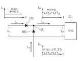
도 1의 본 발명의 일 실시예에 따른 연료전지와 2차 전지를 이용한 하이브리드 전원 공급 장치에 대한 구성도이다.
도 2는 본 발명의 일 실시예에 따른 연료전지 스택의 출력 전류에 따른 출력 전압의 크기를 나타내는 그래프이다.
도 3은 도 1의 하이브리드 전원 공급 장치(100)의 회로 구성을 개략적으로 나타낸 도면이다.
도 4는 본 발명의 일 실시예에 따른 도 1의 하이브리드 전원 공급 장치의 초기 구동시의 동작을 나타내는 전류 그래프이다.
도 5는 본 발명의 일 실시예에 따른 도 1의 하이브리드 전원 공급 장치의 제어부의 구성을 나타내는 도면이다.
도 6은 도 5의 컨버터 제어부의 구성의 일 예를 나타내는 도면이다.
도 7은 도 6의 전류 제어기의 동작을 나타내는 도면이다.
도 8은 도 1의 하이브리드 전원 공급 장치의 부하 변동시의 전류 상태의 일 예를 나타내는 도면이다.
도 9는 도 1의 하이브리드 전원 공급 장치의 부하 변동시의 전류 상태의 다른 예를 나타내는 도면이다.
도 10은 본 발명의 일 실시예에 따른 도 1의 하이브리드 전원 공급 장치의 제어부의 충전 제어 방법을 나타내는 순서도이다.1 is a block diagram of a hybrid power supply using a fuel cell and a secondary battery according to an embodiment of the present invention.
2 is a graph showing the magnitude of the output voltage according to the output current of the fuel cell stack according to an embodiment of the present invention.
3 is a diagram schematically illustrating a circuit configuration of the hybrid
4 is a current graph illustrating an operation during initial driving of the hybrid power supply device of FIG. 1 according to an embodiment of the present invention.
5 is a diagram illustrating a configuration of a control unit of the hybrid power supply device of FIG. 1 according to an embodiment of the present invention.
6 is a diagram illustrating an example of a configuration of the converter controller of FIG. 5.
FIG. 7 is a diagram illustrating an operation of the current controller of FIG. 6.
8 is a diagram illustrating an example of a current state at the time of load variation of the hybrid power supply of FIG. 1.
9 is a diagram illustrating another example of a current state at the time of load variation of the hybrid power supply of FIG. 1.
10 is a flowchart illustrating a charging control method of a controller of the hybrid power supply device of FIG. 1 according to an exemplary embodiment of the present invention.
이하, 첨부된 도면을 참조하여 본 발명의 일 실시예를 상세하게 설명한다. 본 발명을 설명함에 있어 관련된 공지 기능 또는 구성에 대한 구체적인 설명이 본 발명의 요지를 불필요하게 흐릴 수 있다고 판단되는 경우에는 그 상세한 설명을 생략할 것이다. 또한, 후술되는 용어들은 본 발명에서의 기능을 고려하여 정의된 용어들로서 이는 사용자, 운용자의 의도 또는 관례 등에 따라 달라질 수 있다. 그러므로 그 정의는 본 명세서 전반에 걸친 내용을 토대로 내려져야 할 것이다.Hereinafter, an embodiment of the present invention will be described in detail with reference to the accompanying drawings. In the following description of the present invention, a detailed description of known functions and configurations incorporated herein will be omitted when it may make the subject matter of the present invention rather unclear. In addition, the terms described below are defined in consideration of the functions of the present invention, and this may vary depending on the intention of the user, the operator, or the like. Therefore, the definition should be based on the contents throughout this specification.
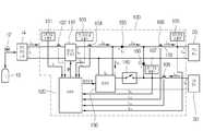
도 1의 본 발명의 일 실시예에 따른 연료전지와 2차 전지를 이용한 하이브리드 전원 공급 장치에 대한 구성도이다.1 is a block diagram of a hybrid power supply using a fuel cell and a secondary battery according to an embodiment of the present invention.
하이브리드 전원 공급 장치(100)는 연료 탱크(10), 연료전지 스택(14), 직류부하(20) 및 2차 전지(30)와 연결된다. 하이브리드 전원 공급 장치(100)는 전기에너지의 공급이 원활하지 못한 독립된 전원 또는 이동상황에서 이용될 수 있다. 하이브리드 전원 공급 장치(100), 연료 탱크(10), 연료전지 스택(14), 직류부하(20) 및 2차 전지(30)를 포함하는 전체 시스템은 전기자동차, 이동식 전자 기기 등일 수 있다.The hybrid
밸브(12)는 연료탱크(10)에 저장되어 있는 H2를 연료전지 스택(14)으로 전달하는 과정에서 수소 공급 압력을 조정한다. 밸브(12)는 연료전지 스택(14)이 정격 출력을 낼 수 있을 만큼의 값으로 압력을 고정한다. 별도의 제어부를 통해 H2의 전달과정의 압력을 변동하여야 하는 기존의 연료전지 발전시스템과 달리, 밸브(12)는 압력을 조정하기 위하여 제어될 필요가 없다.The
연료전지 스택(14)은 직류 전원으로 동작하여 직류 전압 및 직류 전류를 출력한다. 연료전지 스택(14)은 고체 고분자형 연류전지로 구성될 수 있고, 전해질막, 애노드, 캐소드, 세퍼레이터 등으로 구성되는 단셀(도시하지 않음)을 복층 적층한 스택 구조를 이룰 수 있다. 연료전지 스택(14)의 출력 전압이며, 전원 공급 장치(100)의 입력 전압은 Vin으로 나타내며, 연료전지 스택(14)에서 출력되어 전원 공급 장치(100)로 입력되는 입력 전류는 Iin로 나타낸다. 연료전지 스택(14)의 출력전류 (Iin)의 크기는 DC/DC 컨버터(110)의 출력전류(Idc)의 크기와 비례한다. 연료전지 스택(14)의 출력 전압(Vin) 및 출력 전류(Iin)의 관계는 도 2에 나타난다.The
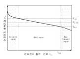
도 2는 본 발명의 일 실시예에 따른 연료전지 스택(14)의 출력 전류(Iin)에 따른 출력 전압(Vin)의 크기를 나타내는 그래프이다.2 is a graph showing the magnitude of the output voltage (Vin ) according to the output current (Iin ) of the
도 2에 도시된 바와 같이, 연료전지 스택(14)의 출력 전류(Iin)의 크기에 따른 출력 전압(Vin)의 크기는 서로 반비례하여, 연료전지 스택(14)의 출력 전류(Iin)가 증가하면 출력 전압(Vin)이 떨어진다. 또한, 그래프의 기울기를 보면, 그래프의 우측으로 갈수록 연료전지 스택(14)의 출력전력이 상승하는 것을 알 수 있다. 도 2의 그래프는, 연료전지 스택(14)의 출력 전류(Iin)에 따른 출력 전압(Vin)에 따라 활성분극 영역(activation region), 저항분극 영역(ohmic region), 농도분극 영역(mass transport region)으로 나누어질 수 있다.As shown in Figure 2, the magnitude of the output voltage (Vin) in accordance with the magnitude of the output current (Iin) of the
다시 도 1을 참조하면, 직류부하(20)는 복수 개의 모듈로 구성될 수 있으며, 내부 모듈의 동작 상태에 따라 직류부하(20)의 크기는 변동될 수 있다. 예를 들어, 직류부하(20)가 휴대 전화를 동작시키기 위한 CPU, 메모리, 통신 모듈 등의 복수의 모듈로 구성될 때 휴대 전화의 전원을 켜는 경우나, 휴대 전화의 동작 상태에 따라 직류부하(20)의 크기가 시시각각 변동될 수 있다. 또한, 직류부하(20)가 전기 자동차에 포함되는 복수의 모듈인 경우, 전기 자동차의 출발시, 차체 중량이 무거워진 경우, 평지주행 후 언덕길 주행, 에어컨 가동시 등 여러 상황에 따라 그 크기가 시시각각 변동될 수 있다. 여기에서는 직류부하(20)가 하이브리드 전원 공급 장치(100)에 연결된 것으로 가정하였으나, 하이브리드 전원 공급 장치(100)로부터 공급되는 직류 전원은 교류 전원으로 변환되어 교류 부하로 공급될 수도 있다. 또한 직류부하는 부하 자체가 직류부하인 경우뿐만 아니라 부하의 입력단이 직류를 사용하는 부하일 수도 있다.Referring back to FIG. 1, the
2차 전지(30)는 연료전지 스택(14)을 이용하여 충전될 수 있는 전지를 나타내며, 충전 물질에 따라 니켈 전지, 리튬 이온 전지 등 다양한 형태의 2차 전지가 이용될 수 있다.The
하이브리드 전원 공급 장치(100)는 DC/DC 컨버터(110), 제어부(120), 충전부(130), 스위치(140), 제1 다이오드(150), 제2 다이오드(160), 복수의 전압 검출부(101, 103, 105, 107) 및 복수의 전류 센서(102, 104, 106, 108)를 포함한다.The hybrid
DC/DC 컨버터(110)는 저전압의 직류전원을 승압하거나 강압하도록 구성될 수 있다. 예를 들어, DC/DC 컨버터(110)는 저전압인 연료 전지 스택(14)의 출력 전압(Vin)으로부터 고전압의 컨버터 전압(Vdc)이 출력되도록 처리하여, 컨버터 전압(Vdc)이 직류부하(20)로 전달되도록 할 수 있다. DC/DC 컨버터(110)는 제어부(120)로부터 입력되는 PWM 신호에 따라 연료전지 스택(14)의 출력 전력을 변환하여 직류 부하(20)로 전달한다. DC/DC 컨버터(110)는 도 2의 저항분극 영역(ohmic region)에서 동작된다.The DC /
연료전지 스택(14)과 DC/DC 컨버터(110)의 사이에 스택전압 검출부(101)와 스택 전류센서(102)가 연결된다. 스택전압 검출부(101)에서 검출된 출력 전압(Vin) 크기 및 스택 전류센서(102)에서 감지된 출력 전류(Iin)의 크기는 제어부(120)로 전달된다.The
제어부(120)는 하이브리드 전원 공급 장치(100)가 연료전지 스택(14) 및 2차 전지(30)를 이용하여, 직류부하(20)가 요구하는 전력을 효율적으로 공급하도록 DC/DC 컨버터(110)의 동작을 제어한다. 특히, 제어부(120)는 직류부하(20)의 변동시에도 연료전지 스택(14)의 수명에 악영향을 미치는 연료전지 스택(14)의 출력에 급격한 변화가 생기는 것을 방지하면서 직류부하(20)가 요구하는 전력을 효율적으로 공급하도록 DC/DC 컨버터(110)의 동작을 제어한다.The
또한, 제어부(120)는 밸브(12)를 별도로 제어하지 않으면서 연료전지 스택(14)의 출력 전류(Iin)가 급격하게 변동되어 출력되는 것을 방지하도록 DC/DC 컨버터(110)의 동작을 제어할 수 있다.In addition, the
도 1의 제1 다이오드(150)는 DC/DC 컨버터(110)에 직렬로 연결되어 DC/DC 컨버터(110)의 전력을 직류 부하(20)로 전달한다. 제2 다이오드(160)는 2차 전지(30)에 직렬로 연결되어, 2차 전지(30)의 전력을 직류 부하(20)로 전달한다. 제1 다이오드(150)와 제2 다이오드(160)는 각각 다이오드(150, 160)에 흐르는 전류가 역방향으로 흐르는 것을 방지한다. 제1 다이오드(150) 양단에 걸리는 전압(Vd1) 및 제2 다이오드(160)의 양단에 걸리는 전압(Vd2)은 각각 일반적으로 약 1[V]일 수 있으나, 여기에서는 설명의 편의를 위하여 O[V]라고 가정한다. 충전부(130)가 2차 전지(30)를 충전하지 않을 때, 제1 다이오드(150)에 흐르는 전류(Idco)는 컨버터 전류(Idc)와 같고, 제2 다이오드(160)에 흐르는 전류를 전지 전류(Ibat)라 한다.The
도 1에서, Iout은 직류부하(20)로 흐르는 부하 전류를 나타내고, Vout은 직류부하(20)에 인가되는 부하 전압을 나타낸다. 연료전지 스택(14)이 DC/DC 컨버터(110)를 통해 직류부하(20)에 전력을 공급할 때 직류부하(20)에 인가되는 전압(Vout)을 Vout1이라고 하고, 2차 전지(30)로부터 직류부하(20)에 전력이 공급될 때 직류부하(20)에 인가되는 전압(Vout)을 Vout2라고 할 때, Vout1 및 Vout2는 다음과 같이 나타낼 수 있다.In FIG. 1, Iout represents a load current flowing into the direct
[수학식 1][Equation 1]
Vout1=Vdc-Vd1=VdcVout1 = Vdc -Vd1 = Vdc
Vout2=Vbat-Vd2=VbatVout2 = Vbat -Vd2 = Vbat
제어부(120)는 후술할 충전 조건이 만족되는지 판단하여, 충전 조건이 만족되는 경우 충전부(130)의 충전을 지시하는 충전 명령을 충전부(130)로 전달한다.The
충전부(130)는 충전 명령에 따라 연료전지 스택(14)으로부터 전원을 2차 전지(30)로 충전한다. 스위치(140)는 충전부(130)의 제어에 따라 충전부(130)가 제어부(120)로부터 충전명령을 받을 때 닫히고, 충전명령이 없을 때에는 열린다. 충전부(130)는 2차 전지(30)가 방전을 하고 있을 때에는 충전 동작을 하지 않는다. 충전부(130)는 DC/DC 컨버터(110)와 제1 다이오드(150) 사이에 병렬로 연결될 수 있다.The charging
출력 라인(170)은 부하(20)에서 요구하는 전력을 제공한다. 출력 라인(170)은 연료전지 스택(14)의 전력, 2차 전지(30)의 전력 또는 연료전지 스택(14) 및 2차 전지(20)의 합산 전력을 부하(20)로 제공한다. 출력 라인(170)은 부하(20)에서 요구하는 전력을 전달하기 위하여, DC/DC 컨버터(110)의 컨버터 전류(Idc)에 의해 제공되지 못하는 크기의 2차 전지(30)의 전지 전류(Ibat) 및 컨버터 전류(Idc)를 합산하여 부하(20)에 전달할 수 있다.
도 3은 도 1의 하이브리드 전원 공급 장치(100)의 회로 구성을 개략적으로 나타낸 도면이다.3 is a diagram schematically illustrating a circuit configuration of the hybrid
스위치(140)가 off 상태인 경우, 도 1의 하이브리드 전원 공급 장치(100)는 도 3에 도시된 바와 같이 2개의 전원이 병렬로 연결되고, 각 전원에 다이오드가 직렬로 연결된 회로로 간략화할 수 있다. 도 3의 저항(R)은 도 1의 직류 부하(20)에 대응한다.When the
컨버터 전압(Vdc)이 전지 전압(Vbat)보다 작은 경우에는, 전류는 b점에서 d점 방향으로만 흐른다. 컨버터 전압(Vdc)에 연결된 제1 다이오드(150)가 b에서 a로는 전류가 흐르는 것을 차단하기 때문이다. 또한, 컨버터 전압(Vdc)이 전지 전압(Vbat)보다 큰 경우에는, 전류는 a점에서 d점 방향으로만 흐른다. 즉, 제1 다이오드(150) 및 제2 다이오드(160)로 인하여, 2개의 전압원이 병렬로 연결되어 있을 때, 2개의 전압원 중 높은 전압원에서만 전류가 저항(R)으로 흐르도록 할 수 있다.When the converter voltage Vdc is smaller than the battery voltage Vbat , the current flows only in the direction of point b to point d. This is because the
컨버터 전압(Vdc)이 전지 전압(Vbat)과 같은 경우에는, a점과 b점의 전위가 같으므로 전류는 a점에서 c점으로, b점에서 d점으로 같은 크기의 전류가 저항(R)을 통해 흐른다. 도 1에서 전지 전압(Vbat)은 만충시와 방전시에 전압 크기의 차이가 있지만 일반적으로 고정된 전압으로 볼 수 있다. 이에 반해, DC/DC 컨버터(110)는 전력 변환기로써, 입력 전력을 원하는 형태의 출력 전력(출력 전압, 출력 전류)로 변환시킬 수 있다. 컨버터 전압(Vdc)의 크기에 따라서, 부하 저항(R)에 흐르는 전류는 DC/DC 컨버터(110)로부터 출력되는 컨버터 전류(Idc)이거나 2차 전지(30)로부터 출력되는 전지 전류(Ibat)일 수 있다. 또한, 컨버터 전류(Idc) 및 전지 전류(Ibat)가 더해져 저항(R)에 흐를 수도 있다. DC/DC 컨버터(110)로부터 출력되는 컨버터 전류(Idc)의 크기는 제어부(120)에 의해 제어될 수 있다.If the converter voltage (Vdc ) is equal to the battery voltage (Vbat ), the potentials of point a and point b are the same, so the current is the same size from point a to point c and point b to point d. R) flows through. In FIG. 1, the battery voltage Vbat may be regarded as a fixed voltage, although there is a difference in voltage magnitude at full charge and at discharge. In contrast, the DC /
이하에서는, 도 1 내지 도 4를 참조하여, 하이브리드 전원 공급 장치(100)의 동작을 설명한다.Hereinafter, the operation of the hybrid
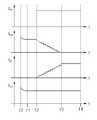
도 4는 본 발명의 일 실시예에 따른 도 1의 하이브리드 전원 공급 장치(100)의 초기 구동시의 동작을 나타내는 전류 그래프이다.4 is a current graph illustrating an operation during initial driving of the hybrid
시간 to에서 직류부하(20)가 처음으로 기동을 시작하게 되면 2차 전지(30)로부터 제2 다이오드(160)를 통해 직류부하(20)에 전력이 공급된다.When the
[t0~t1] 시간 구간은 직류부하(20)가 처음 기동시에 돌입전류를 포함한 과도전류가 2차 전지(30)의 전류가 직류부하(20)로 흐르는 것을 나타낸다. 2차 전지 전류센서(108)와 전지전압 검출부(107)는 전지 전류(Ibat)와 전지 전압(Vbat)을 측정하여 그 값을 제어부(120)로 전달하고, 부하전압 검출부(105) 및 부하 전류 센서(106)는 부하 전압(Vout) 및 부하 전류(Iout)를 측정하여 그 값을 제어부(120)로 전달한다.[t0 to t1 ] The time interval indicates that when the
[t1~t2] 구간은 직류부하(20)가 점차 안정화되어 직류부하(20)로 흐르는 전류가 정상 상태에 도달하는 모습이다. 제어부(120)는 일정시간 동안 2차 전지(30)로부터 입력되는 전지 전류(Ibat)의 평균전류를 기준으로 일정 오차 범위 내에서 전지 전류(Ibat)가 연속적으로 흐를 때 정상상태라고 결정할 수 있다. [t1~t2] 구간에서도 직류부하(20)의 전력공급은 오로지 2차 전지(30)를 통해서만 이루어진다. 제어부(120)는 감지된 부하 전류(Iout) 및 전지 전류(Ibat)가 정상 상태에 도달하면, DC/DC 컨버터(110)를 제어하는 PWM 신호 생성에 이용되는 전류 지령치(Idc*)를 생성할 수 있다. 전류 지령치(Idc*)는 DC/DC 컨버터(110)에 출력되며 컨버터 전류 센서(12)에서 감지되는 출력 전류(Idc) 기준 전류값이다.[t1 ~ t2 ] is a state in which the
[t2~t3] 구간은 [t1~t2] 구간에서 만들어진 전류 지령치(Idc*)를 이용하여 DC/DC 컨버터(110)가 기동을 시작하는 구간이다. 기동 초기에 연료전지 스택(14)의 출력 전력은 작으며, 정격 출력까지 내는데는 수초의 시간이 걸릴 수 있다. DC/DC 컨버터(110)는 2차 전지(30)와 직류 부하(20)를 분담하기 위해서 DC/DC 컨버터(110)의 출력 전류를 조금씩 증가시키는데, 이는 DC/DC 컨버터(110)의 출력 전압을 제어함으로써 가능하다. t2에서 t3로 시간이 흐를수록 연료전지 스택(14)의 출력 전력은 상승하고, DC/DC 컨버터(110)의 출력 전류도 상승하게 된다.[t2 ~ t3 ] section is a section in which the DC /
시간 t3 이후에서, DC/DC 컨버터(110)의 입력 전력이 직류 부하(20)를 전담할만큼 커져, DC/DC 컨버터(110)의 컨버터 전압(Vdc)이 전지 전압(Vbat)보다 크도록 제어가 되며, 직류 부하(20)에 흐르는 전류는 모두 DC/DC 컨버터(110)로부터 흐르게 된다.After time t3 , the input power of the DC /
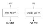
도 5는 본 발명의 일 실시예에 따른 도 1의 하이브리드 전원 공급 장치(100)의 제어부(120)의 구성을 나타내는 도면이다.5 is a diagram illustrating a configuration of the
제어부(120)는 전압 지령치(Vdc*) 및 전류제한치(Idc_lim)를 결정하여 PWM 신호를 생성하고, 생성된 PWM 신호를 DC/DC 컨버터(110)에 제공하여 컨버터 전압(Vdc) 및 컨버터 전류(Idc)의 크기를 조정한다.The
제어부(120)는 정보 처리부(122) 및 컨버터 제어부(124)를 포함할 수 있다.The
정보 처리부(122)는 복수의 전압 검출부(101, 103, 105, 107) 및 복수의 전류 센서(102, 104, 106, 108)로부터 감지된 전압 값 및 전류 값을 이용하여 컨버터 제어부(124)를 제어한다. 정보 처리부(122)는 컨버터 제어부(124)의 동작에 필요한 정보인 도 5의 전압 지령치(Vdc*) 및 전류제한치(Idc_lim)를 결정하여 컨버터 제어부(124)로 전달할 수 있다.The
상세하게는, 전지 전압 검출부(107)로부터 검출된 전지 전압(Vbat)을 이용하여 전지 전압(Vbat)보다 높은 전압 지령치(Vdc*)를 결정하여 컨버터 제어부(124)로 제공할 수 있다. 또한, 정보 처리부(122)는 연료전지 스택(14)의 출력 전압(Vin)에 따라 전류제한치(Idc_lim)를 결정하여 컨버터 제어부(124)로 제공할 수 있다.In detail, the voltage command value Vdc * higher than the battery voltage Vbat may be determined and provided to the
또한, 정보 처리부(122)는 충전 조건이 만족하는지를 결정하여, 도 1의 충전부(130)로 충전 명령을 전달할 수 있다.In addition, the
컨버터 제어부(124)는 직류부하(20)의 변동시에도 연료전지 스택(14)의 수명에 악영향을 미치는 연료전지 스택(14)의 출력에 급격한 변화가 생기는 것을 방지하면서 직류부하(20)가 요구하는 전력을 효율적으로 공급하도록 하는 PWM 신호를 생성하여 DC/DC 컨버터(110)에 제공하여 DC/DC 컨버터(110)의 동작을 제어한다. 이를 통해, 컨버터 제어부(124)는 밸브(12)를 별도로 제어하지 않으면서 연료전지 스택(14)의 출력 전류(Iin)가 급격하게 변동되어 출력되는 것을 방지하도록 DC/DC 컨버터(110)의 동작을 제어할 수 있다.The
도 6은 도 5의 컨버터 제어부(124)의 구성의 일 예를 나타내는 도면이다.6 is a diagram illustrating an example of a configuration of the
컨버터 제어부(124)는 제1 차분기(510), 전압 비례 적분 제어기(520), 리미트(530), 전류 제어부(540), 제2 차분기(550), 전류 비례 적분 제어기(560) 및 PWM 발생기(570)를 포함할 수 있다.The
제1 차분기(510)는 도 5의 정보 처리부(122)에서 결정된 전압 지령치(Vdc*)와 도 1의 컨버터 전압 검출부(103)로부터 검출된 컨버터 전압(Vdc) 사이의 차분 오차를 생성한다. 전압 비례 적분 제어기(520)는 전압 지령치(Vdc*)와 컨버터 전압(Vdc) 사이의 오차를 최소화하도록 비례적 적분 연산을 수행한다. 전압 비례 적분 제어기(520)의 출력은 전류에 대한 값(Idc_1*)으로 출력하여 리미트(530)로 입력된다.The
리미트(530)는 입력 값(Idc_1*)을 소정의 값 이하로 제한하여 출력하는 장치이다. 리미트(530)는 전압 비례 적분 제어기(520)의 출력은 전류에 대한 값(Idc_1*)을 전류제한치(Idc_lim) 이하로 제한하여 전류 지령치(Idc*)를 출력한다. 여기에서, 전류제한치(Idc_lim)는 연료전지 스택(14)의 출력 전압(Vin)에 따라 조정될 수 있다.The
리미트(530)를 사용함으로써, 하이브리드 전원 공급 장치(100)의 초기 기동시에 전압 지령치(Vdc*)와 컨버터 전압(Vdc) 사이의 큰 차이로 인하여 전류지령치(Idc*)가 급격히 커지는 것을 방지할 수 있다. 또한, 리미트(530)의 전류제한치(Idc_lim)를 조정함으로써 연료전지 스택(14)의 출력 전류(Iin)의 크기를 제어할 수 있다.By using a
도 7은 도 6의 전류 제어기의 동작을 나타내는 도면이다. 도 7에 도시된 바와 같이 전류 지령치(Idc*)는 전류 제어부(540)에서 처리되어 전류지령치(Idc_2*)와 같은 형태로 출력된다.FIG. 7 is a diagram illustrating an operation of the current controller of FIG. 6. As illustrated in FIG. 7, the current command value Idc * is processed by the
제2 차분기(550)는 전류지령치(Idc_2*)와 컨버터 전류(Idc) 사이의 차분 오차를 생성한다.The seconddivider 550 generates a difference error between the current command value Idc_2 * and the converter current Idc .
전류 비례 적분 제어기(560)는 전류 지령치(Idc_2*)와 컨버터 전류(Idc) 사이의 오차를 최소화하도록 비례적 적분 연산을 수행한다. 전류 비례 적분 제어기(560)의 출력은 전압에 대한 전압 기준치(Vdc_ref)로 출력하여 PWM 발생기(570)로 입력된다.The current
PWM 발생기(570)는, 전압 기준치(Vdc_ref) 및 반송파(또는 삼각파)를 비교하여 PWM 신호의 듀티를 결정하고, 듀티에 따른 PWM 신호를 발생할 수 있다. PWM 신호 발생기(570)는 전압지령치(Vdc_ref) 및 반송파의 비교 결과, 전압 기준치(Vdc_ref)가 반송파보다 크면 하이 레벨의 신호를 출력하고, 전압 기준치(Vdc_ref)가 반송파보다 작으면 로우 레벨의 신호를 출력할 수 있다.The
이하에서는, 리미트(530)의 전류제한치(Idc_lim)를 설정하는 방법에 대하여 설명한다.Hereinafter, a method of setting the current limit value Idc_lim of the limit 530 will be described.
도 2에서 DC/DC 컨버터(110)의 동작 영역인 저항분극 영역(ohmic region)의 출력 전압(Vin)을 참조하면, 도 1의 제어부(120)(또는 도 5의 정보 처리부(122))는 저항분극 영역의 최소 전압값(Vin_min) 및 정격 출력 전압(Vin_normal)을 결정할 수 있다.Referring to the output voltage Vin of the ohmic region, which is an operating region of the DC /
연료전지 스택(14)의 출력 전압(Vin)이 제1 조건(Vin≤Vin_min)을 만족하는 경우, 연료전지 스택(14)의 출력 전류(Iin)가 저항분극 영역의 최소 전압값(Vin_min)에 대응되는 최대 전류값(Iin_max) 이상으로 흐르게 된다. 이러한 경우, 연료전지 스택(14)의 출력 전류(Iin)를 제한하여 연료전지 스택(14)을 보호해야 한다. 제어부(120)는 리미트(530)의 전류제한치(Idc_lim)를 조정하여 연료전지 스택(14)의 출력 전류(Iin)를 제한할 수 있다.When the output voltage Vin of the
상세하게는, P=VI이므로, 연료전지의 출력전압(Vin)이 저항분극 영역의 최소 전압값(Vin_min)보다 작아진다는 것은 연료전지의 출력 전력이 정격 출력 전력보다 더 커지는 것을 의미한다. 따라서, DC/DC 컨버터(110)의 출력 전력을 줄여야 연료전지 스택(14)의 출력 전력도 줄어든다. DC/DC 컨버터(110)의 출력 전력을 줄이기 위해 전류제한치(Idc_lim)을 줄이게 되면 전류지령치(Idc*)가 작아지게 되므로 이에 따라 PWM을 하면, 전류(Idc)가 줄어들고, 그에 따라 연료전지 출력 전류(Iin)가 줄어들게 된다.Specifically, since P = VI, the output voltage Vin of the fuel cell being smaller than the minimum voltage value Vin_min of the resistance polarization region means that the output power of the fuel cell is larger than the rated output power. . Therefore, the output power of the
전류제한치(Idc_lim)를 조정하는 과정은 수학식 2로 나타낼 수 있다.The process of adjusting the current limit (Idc_lim ) can be represented by Equation 2.
[수학식 2]&Quot; (2) "
Idc_limit`= Idc_lim-ΔIIdc_limit `= Idc_lim -ΔI
여기에서, Idc_limit`는 조정 후 전류제한치를 나타내며, ΔI는 전류제한치(Idc_lim)를 감소시키기 위한 값으로, 양의 값인 소정의 값으로 설정될 수 있다.Here, Idc_limit ′ represents the current limit after adjustment, and ΔI is a value for decreasing the current limit value Idc_lim and may be set to a predetermined value which is a positive value.
즉, 제어부(120)는, 연료전지 스택(14)의 출력 전압(Vin)이 연료전지 스택(14)의 동작 영역 중 저항분극 영역의 최소 전압값(Vin_min) 이하가 되면, 전류제한치(Idc_lim)가 감소되도록 조정할 수 있다.That is, when the output voltage Vin of the
또한, 연료전지 스택(14)의 출력 전압(Vin)이 제2 조건(Vin>Vnormal)을 만족하는 경우, 연료전지 스택(14)의 출력 전류(Iin)가 연료전지 스택(14)의 정격 출력보다 작게 흐르게 된다. 따라서, 제어부(120)는 연료전지의 출력 전류(Iin)가 저항분극 영역의 최소 전압값(Vin_min)에 대응되는 저항분극 영역에서의 최대 전류값(Iin_max)이하가 되는 범위 내에서, 전류제한치(Idc_lim)가 증가되도록 조정할 수 있다.In addition, when the output voltage Vin of the
이와 같은 방법으로, 밸브(12)에 대한 특별한 제어 없이 고정적인 압력으로 H2가 연료전지 스택(14)에 공급되더라도 연료전지 스택(14)의 출력 전류(Iin)을 조정하는 효과를 달성할 수 있다. 즉, 밸브(12)에 대한 제어를 위한 별도의 모듈이 부가되지 않아도 되므로 하이브리드 전원 공급 장치(100)의 소형화가 가능하다.In this way, it is possible to achieve the effect of adjusting the output current Iin of the
도 8은 도 1의 하이브리드 전원 공급 장치(100)의 부하 변동시의 전류 상태의 일 예를 나타내는 도면이다.8 is a diagram illustrating an example of a current state at the time of load variation of the hybrid
도 8에서 부하(20)는 직류전력을 소비하는 부하이며, 부하(20)의 크기가 수시로 변하는 특성이 있다. 부하(20)의 크기가 수시로 변하는 경우 부하(20)에 흐르는 전류(Iout)에 리플이 발생을 하게 된다.In FIG. 8, the
제어부(120)는 부하 전류 센서(106)로부터의 검출 값을 이용하여 부하 전류(Iout)에 리플이 발생함을 알 수 있다. 이 경우, 제어부(120)는 PWM 신호를 이용하여 DC/DC 컨버터(110)가 일정한 컨버터 전류(Idc)를 출력하도록 하여 컨버터 전압(Vdc)을 제어한다. 그러면, 부하 전류(Iout)의 리플에 해당하여 요구되는 변동 전류는 자동적으로 2차 전지(30)로부터의 전류(Ibat)에서 분담하게 된다.The
따라서, 부하(20)가 요구하는 시변하는 전력을 제공하면서도 컨버터 전류(Idc)에는 리플이 발생되지 않아서 컨버터 전류(Idc)에 영향을 받는 연료전지 스택(14)의 출력 전류(Iin)에도 리플이 발생되는 것을 방지할 수 있다.Thus, the
도 9는 도 1의 하이브리드 전원 공급 장치(100)의 부하 변동시의 전류 상태의 다른 예를 나타내는 도면이다.9 is a diagram illustrating another example of a current state at the time of load variation of the hybrid
DC/DC 컨버터(110)에서 부하(20)에 전력을 일정하게 공급하고 있는 상황에서, 부하(20)의 크기가 일정하게 유지되다 갑자기 커지는 경우, 연료전지 스택(14)을 보호하기 위하여 연료전지 스택(14)의 출력 전력은 천천히 상승해야 하고, 이에 따라 DC/DC 컨버터(110)의 출력 전력은 부하(20)가 요구되는 전력에 비하여 천천히 상승해야 한다. 다시 말하면, DC/DC 컨버터(110)의 측면에서 DC/DC 컨버터(110)는 부하(20)에 맞게 부하 전류(Iout)가 급격하게 상승함에 따라 컨버터 전류(Idc)를 증가시키려고 하지만, DC/DC 컨버터(110)의 출력 전력은 천천히 상승하므로, V=P/I를 고려하면 컨버터 전압(Vdc)이 작아지게 된다.In the situation where the DC /
따라서, 컨버터 전압(Vdc)이 배터리 전압(Vbat)보다 작아지는 순간 2차전지(30)로부터 전류가 공급되어, 순간적으로 2차 전지(30)에서 부하(20)의 상승분에 대한 전력을 공급하게 된다.Therefore, when the converter voltage Vdc becomes smaller than the battery voltage Vbat , a current is supplied from the
DC/DC 컨버터(110)의 출력 전력은 연료전지 스택(14)의 출력 전력이 상승하는 것과 비교하여 완만하게 컨버터 전류(Idc)가 증가하도록 제어한다. 그리고, 시간이 지나서, 연료전지 스택(14)의 출력 전력이 부하(20)에서 요구되는 크기의 전력만큼 상승하게 되면, 부하(20)에 공급되는 전력은 DC/DC 컨버터(110)의 출력 전력이 된다.The output power of the DC /
상세하게는, 제어부(120)는 부하(20)에서 요구되는 전력에 따라 연료전지 스택(14)의 출력 전압(Vin)에 급격한 변화가 생기지 않도록 전압 지령치(Vdc*)가 천천히 상승하도록 제어하고, 이에 따라, 컨버터 전압(Vdc)이 전압 지령치(Vdc*)로 제어되고 컨버터 전류(Idc)가 전류지령치(Idc*)로 제어되어, 컨버터 전류(Idc)가 전류지령치(Idc*)에 일치하게 되면 다시 연료전지 스택(14)의 전력으로만 부하(20)를 구동할 수 있다. 또한, 급격하게 부하가 증가하면 컨버터 전압(Vdc)이 떨어지므로 도 5에서 전압지령치(Vdc*)와 컨버터 전압(Vdc)의 오차가 커지게 되며, 따라서 전류 지령치(Idc*1)와 전류지령치(Idc*)역시 커지게 된다. 이에 따라, 급격한 부하 증가시에 전류 지령치(Idc*)가 상승될 수 있으므로, 컨버터 전류(Idc)가 상승되도록 제어될 수 있다.In detail, the
도 10은 본 발명의 일 실시예에 따른 도 1의 하이브리드 전원 공급 장치(100)의 제어부(120)의 충전 제어 방법을 나타내는 순서도이다.10 is a flowchart illustrating a charging control method of the
도 10은 잦은 부하(20)의 기동과 정지로 인하여 2차 전지(30)의 충전이 필요할 때에 도 1의 제어부(120)가 충전부(130)에 충전명령을 내릴 수 있는 조건을 순서도로 나타내었다.FIG. 10 is a flow chart illustrating conditions under which the
충전명령을 내릴 수 있는 조건을 만족하게 되면 충전부(130)는 스위치(140)를 닫고, 2차 전지(30)를 충전하게 된다.When the condition for giving a charging command is satisfied, the charging
충전명령을 내릴 수 있는 조건은 2차 전지(30)의 전압조건, 연료전지 스택(14)의 출력전력 조건, DC/DC 컨버터(110)의 출력전압 조건이 있다. 제어부(120)는 이 3가지의 조건을 동시에 만족을 하는 경우 충전부(130)로 충전명령을 내린다. 제어부(120)는 도 10의 순서도에 나와 있는 루틴을 부하(20)가 기동함과 동시에 일정주기로 무한히 반복하여 체크할 수 있다.Conditions for giving a charge command include a voltage condition of the
제어부(120)는 2차 전지(30)의 전압조건을 만족하는지 결정하기 위하여 단계 910, 912 및 914를 수행한다. 제어부(120)는 도 1의 전지 전압 검출부(107)로부터 검출된 전지 전압(Vbat)을 판독한다(910). 제어부(120)는 2차 전지(30)가 방전이 심하게 되어 수명이 다했거나 만충이 된 경우에는 충전을 하지 않기 위하여, 2차 전지(30)의 전지 전압(Vbat)이 완전 방전시의 하한 전지 전압(Vbat_low)보다 크고(912), 전지 전압(Vbat)이 만충치의 상한 전지 전압(Vbat_high)보다 작으면(914), 2차 전지(30)의 전압 조건을 만족하는 것으로 결정한다.The
제어부(120)는 연료전지 스택(14)의 출력전력 조건을 만족하는지 결정하기 위하여, 단계 920, 922, 924 및 926을 수행한다. 제어부(120)는 도 1의 스택전압 검출부(101)로부터 검출된 출력 전압(Vin)을 판독하고(920), 도 1의 전류 센서(102)로부터 검출된 출력 전류(Iin)을 판독하고(922), 출력 전압(Vin) 및 출력 전류(Iin)를 이용하여 연료전지 스택(14)의 출력 전력(Win)을 계산한다(924). 제어부(120)는 연료전지 스택의 출력 전력(Win)이 연료전지 스택의 정격 출력 전력(Win_normal)보다 작으면(926), 연료전지 스택(14)의 출력전력 조건을 만족하는 것으로 결정한다. 연료전지 스택(14)의 출력 전력(Win)이 연료전지 스택의 정격 출력 전력(Win_normal)보다 크거나 같으면, 충전명령을 내릴 수 없도록 하여, 연료전지 스택(14)을 보호하기 위함이다.The
제어부(120)는 DC/DC 컨버터(110)의 출력전압 조건을 만족하는지 결정하기 위하여 단계 930 및 932를 수행한다. 제어부(120)는 도 1의 컨버터 전압 검출부(103)로부터 검출된 컨버터 전압(Vdc)을 판독하고(930), 컨버터 전압(Vdc)이 2차 전지(30)의 전지 전압(Vbat)보다 크면(932), DC/DC 컨버터(110)의 출력전압 조건을 만족하는 것으로 결정한다. 컨버터 전압(Vdc)이 2차 전지(30)의 전지 전압(Vbat)보다 낮으면, 전위차에 의해 2차 전지(30)의 전력이 직류부하(20)로 전달되므로, 2차 전지(30)가 방전하는 상태에서는 2차 전지(30)를 충전하지 않도록 하기 위함이다.The
제어부(120)는 2차 전지(20)의 전압조건, 연료전지 스택(14)의 출력전력 조건, DC/DC 컨버터(110)의 출력전압 조건이 모두 만족하는 경우, 충전부(130)로 충전명령을 발생한다(940).When the voltage condition of the
본 발명의 일 양상은 컴퓨터로 읽을 수 있는 기록 매체에 컴퓨터가 읽을 수 있는 코드로서 구현될 수 있다. 상기의 프로그램을 구현하는 코드들 및 코드 세그먼트들은 당해 분야의 컴퓨터 프로그래머에 의하여 용이하게 추론될 수 있다. 컴퓨터가 읽을 수 있는 기록매체는 컴퓨터 시스템에 의하여 읽혀질 수 있는 데이터가 저장되는 모든 종류의 기록 장치를 포함한다. 컴퓨터가 읽을 수 있는 기록 매체의 예로는 ROM, RAM, CD-ROM, 자기 테이프, 플로피 디스크, 광 디스크 등을 포함한다. 또한, 컴퓨터가 읽을 수 있는 기록 매체는 네트워크로 연결된 컴퓨터 시스템에 분산되어, 분산 방식으로 컴퓨터가 읽을 수 있는 코드로 저장되고 실행될 수 있다.One aspect of the present invention may be embodied as computer readable code on a computer readable recording medium. The code and code segments implementing the above program can be easily deduced by a computer programmer in the field. A computer-readable recording medium includes all kinds of recording apparatuses in which data that can be read by a computer system is stored. Examples of the computer-readable recording medium include ROM, RAM, CD-ROM, magnetic tape, floppy disk, optical disk, and the like. The computer-readable recording medium may also be distributed over a networked computer system and stored and executed in computer readable code in a distributed manner.
이상의 설명은 본 발명의 일 실시예에 불과할 뿐, 본 발명이 속하는 기술분야에서 통상의 지식을 가진 자는 본 발명의 본질적 특성에서 벗어나지 않는 범위에서 변형된 형태로 구현할 수 있을 것이다. 따라서, 본 발명의 범위는 전술한 실시예에 한정되지 않고 특허 청구범위에 기재된 내용과 동등한 범위 내에 있는 다양한 실시 형태가 포함되도록 해석되어야 할 것이다.It will be apparent to those skilled in the art that various modifications and variations can be made in the present invention without departing from the spirit or scope of the invention. Therefore, the scope of the present invention should not be limited to the above-described embodiments, but should be construed to include various embodiments within the scope of the claims.
14: 연료전지 스택 20: 직류부하
30: 2차 전지 110: DC/DC 컨버터
120: 제어부 130: 충전부
140: 스위치 150: 제1 다이오드
160: 제2 다이오드14: fuel cell stack 20: direct current load
30: secondary battery 110: DC / DC converter
120: control unit 130: charging unit
140: switch 150: first diode
160: second diode
Claims (7)
Translated fromKorean연료전지 스택의 출력 전력을 PWM 신호에 따라 변환하여 부하로 전달하는 DC/DC 컨버터;
2차 전지의 전지 전압보다 높게 설정된 DC/DC 컨버터의 컨버터 전압(Vdc)에 대한 전압 지령치(Vdc*) 및 상기 연료전지 스택의 출력 전압에 기초하여 상기 DC/DC 컨버터의 컨버터 전류(Idc)의 크기를 제한하는 전류제한치(Idc_lim)를 이용하여 PWM 신호를 생성하고 생성된 PWM 신호를 DC/DC 컨버터에 제공하여 상기 컨버터 전압(Vdc) 및 상기 컨버터 전류(Idc)의 크기를 조정하는 제어부; 및
상기 연료전지 스택의 전력, 상기 2차 전지의 전력 또는 상기 연료전지 스택 및 상기 2차 전지의 합산 전력을 상기 부하로 제공하는 출력 라인; 을 포함하며,
상기 제어부는, 연료 탱크로부터 상기 연료전지 스택으로 공급되는 수소 연료의 공급 압력을 별도로 제어하지 않으면서, 연료전지 스택의 출력 전압(Vin)이 상기 연료전지 스택의 동작 영역 중 저항분극 영역의 최소 전압값(Vin_min) 이하가 되면, 상기 전류제한치(Idc_lim)가 감소되도록 조정하는 것을 특징으로 하는 하이브리드 전원 공급 장치.In the hybrid power supply for supplying power to the load using a secondary cell connected in parallel with the fuel cell stack with respect to the fuel cell stack and the load,
A DC / DC converter converting the output power of the fuel cell stack according to the PWM signal and transferring the output power to the load;
The converter current (I) of the DC / DC converter based on the voltage command value (Vdc *) for the converter voltage (Vdc ) of the DC / DC converter set higher than the battery voltage of the secondary battery and the output voltage of the fuel cell stack.DC to generate a PWM signal by using the current limit (Idc_lim ) limiting the size of the current and provide the generated PWM signal to the DC / DC converter to the magnitude of the converter voltage (Vdc ) and the converter current (Idc ) Control unit for adjusting the; And
An output line providing power of the fuel cell stack, power of the secondary cell, or total power of the fuel cell stack and the secondary cell to the load; / RTI >
The controller does not separately control the supply pressure of the hydrogen fuel supplied from the fuel tank to the fuel cell stack, and the output voltage Vin of the fuel cell stack is the minimum of the resistance polarization region in the operation region of the fuel cell stack. And when the voltage value is lower than Vin_min , adjusting the current limit value Idc_lim to be reduced.
연료전지 스택의 출력 전력을 PWM 신호에 따라 변환하여 부하로 전달하는 DC/DC 컨버터;
2차 전지의 전지 전압보다 높게 설정된 DC/DC 컨버터의 컨버터 전압(Vdc)에 대한 전압 지령치(Vdc*) 및 상기 연료전지 스택의 출력 전압에 기초하여 상기 DC/DC 컨버터의 컨버터 전류(Idc)의 크기를 제한하는 전류제한치(Idc_lim)를 이용하여 PWM 신호를 생성하고 생성된 PWM 신호를 DC/DC 컨버터에 제공하여 상기 컨버터 전압(Vdc) 및 상기 컨버터 전류(Idc)의 크기를 조정하는 제어부; 및
상기 연료전지 스택의 전력, 상기 2차 전지의 전력 또는 상기 연료전지 스택 및 상기 2차 전지의 합산 전력을 상기 부하로 제공하는 출력 라인; 을 포함하며,
상기 제어부는, 연료전지 스택의 출력 전압(Vin)이 연료전지 스택의 정격 전압(Vin_normal)보다 큰 경우, 연료전지 스택의 출력 전류(Iin)가 상기 연료전지 스택의 동작 영역 중 저항분극 영역의 최소 전압값(Vin_min)에 대응되는 저항분극 영역에서의 최대 전류값(Iin_max)이하인 범위 내에서, 상기 전류제한치(Idc_lim)가 증가되도록 조정하는 것을 특징으로 하는 하이브리드 전원 공급 장치In the hybrid power supply for supplying power to the load using a secondary cell connected in parallel with the fuel cell stack with respect to the fuel cell stack and the load,
A DC / DC converter converting the output power of the fuel cell stack according to the PWM signal and transferring the output power to the load;
The converter current (I) of the DC / DC converter based on the voltage command value (Vdc *) for the converter voltage (Vdc ) of the DC / DC converter set higher than the battery voltage of the secondary battery and the output voltage of the fuel cell stack.DC to generate a PWM signal by using the current limit (Idc_lim ) limiting the size of the current and provide the generated PWM signal to the DC / DC converter to the magnitude of the converter voltage (Vdc ) and the converter current (Idc ) A control unit for adjusting the; And
An output line providing power of the fuel cell stack, power of the secondary cell, or total power of the fuel cell stack and the secondary cell to the load; / RTI >
Wherein, when the output voltage (Vin) of the fuel cell stack is greater than the nominal voltage (Vin_normal) of the fuel cell stack, the output current (Iin) is the operating region of the resistance polarization of the fuel cell stack of the fuel cell stack Hybrid power supply, characterized in that for adjusting the current limit (Idc_lim ) is increased within the range of less than the maximum current value (Iin_max ) in the resistance polarization region corresponding to the minimum voltage value (Vin_min ) of the region.
DC/DC 컨버터에 직렬로 연결되어, DC/DC 컨버터의 전력을 상기 부하로 전달하는 제1 다이오드; 및
2차 전지에 직렬로 연결되어, 2차 전지의 전력을 상기 부하로 전달하는 제2 다이오드;를 더 포함하는 것을 특징으로 하는 하이브리드 전원 공급 장치.The method according to claim 2 or 3,
A first diode connected in series with a DC / DC converter and transferring power of the DC / DC converter to the load; And
And a second diode connected in series to the secondary battery and transferring power of the secondary battery to the load.
DC/DC 컨버터와 제1 다이오드 사이에 병렬로 연결되어, 2차 전지를 충전할 수 있는 충전부; 및
충전부와 2차 전지 사이의 접속을 연결하거나 차단하는 스위치;를 더 포함하는 것을 특징으로 하는 하이브리드 전원 공급 장치.5. The method of claim 4,
A charging unit connected in parallel between the DC / DC converter and the first diode to charge the secondary battery; And
And a switch for connecting or disconnecting the connection between the charging unit and the secondary battery.
전지 전압(Vbat)이 완전 방전시의 하한 전지 전압(Vbat_low)보다 크고 만충치의 상한 전지 전압(Vbat_high)보다 작으면 만족되는 2차 전지의 전지 전압 조건, 연료전지 스택의 출력 전력(Win)이 연료전지 스택의 정격 출력 전력(Win_normal)보다 작은 경우 만족되는 연료전지 스택의 출력전력 조건 및 컨버터 전압(Vdc)이 2차 전지의 전지 전압(Vbat)보다 크면 만족되는 DC/DC 컨버터의 출력전압 조건을 모두 만족하는 경우, 상기 제어부는 충전명령을 발생하여 상기 충전부로 전달하는 것을 특징으로 하는 하이브리드 전원 공급 장치.The method of claim 5,
When the battery voltage (Vbat ) is higher than the lower limit battery voltage (Vbat_low ) at full discharge and lower than the upper limit battery voltage (Vbat_high ) of the full charge, the battery voltage condition of the secondary battery, the output power of the fuel cell stack (W)in ) is less than the rated output power (Win_normal ) of the fuel cell stack, the DC / s satisfying the output power condition of the fuel cell stack and the converter voltage (Vdc ) is greater than the battery voltage (Vbat ) of the secondary cell. When all the output voltage conditions of the DC converter is satisfied, the control unit generates a charging command and delivers to the charging unit.
상기 출력 라인은 상기 연료전지 스택 및 2차 전지 둘 다로부터 부하에서 요구되는 전력을 제공하는 경우, 상기 컨버터 전류(Idc)에 의해 제공되지 못하는 크기의 상기 2차 전지의 전지 전류 및 상기 컨버터 전류(Idc)를 합산하여 상기 부하에 전달하는 것을 특징으로 하는 하이브리드 전원 공급 장치.The method according to claim 2 or 3,
The output line is the battery current and the converter current of the secondary battery of a size not provided by the converter current Idc when providing the required power at the load from both the fuel cell stack and the secondary battery. (Idc ) summing and delivering to the load.
Priority Applications (1)
| Application Number | Priority Date | Filing Date | Title |
|---|---|---|---|
| KR1020120099467AKR101351349B1 (en) | 2012-09-07 | 2012-09-07 | Hybrid power supply apparatus using fuel cell and rechargeable battery |
Applications Claiming Priority (1)
| Application Number | Priority Date | Filing Date | Title |
|---|---|---|---|
| KR1020120099467AKR101351349B1 (en) | 2012-09-07 | 2012-09-07 | Hybrid power supply apparatus using fuel cell and rechargeable battery |
Publications (1)
| Publication Number | Publication Date |
|---|---|
| KR101351349B1true KR101351349B1 (en) | 2014-01-15 |
Family
ID=50145522
Family Applications (1)
| Application Number | Title | Priority Date | Filing Date |
|---|---|---|---|
| KR1020120099467AActiveKR101351349B1 (en) | 2012-09-07 | 2012-09-07 | Hybrid power supply apparatus using fuel cell and rechargeable battery |
Country Status (1)
| Country | Link |
|---|---|
| KR (1) | KR101351349B1 (en) |
Cited By (11)
| Publication number | Priority date | Publication date | Assignee | Title |
|---|---|---|---|---|
| KR101707072B1 (en)* | 2015-11-04 | 2017-02-15 | 재단법인대구경북과학기술원 | hybrid power supply with fuel cell and battery and operating method thereof |
| KR101756210B1 (en)* | 2015-12-29 | 2017-07-27 | 재단법인대구경북과학기술원 | Hybrid Electricity Supplying Device Containing Solid Oxide Fuel Cell and Secondary Battery |
| KR20170122063A (en)* | 2016-04-26 | 2017-11-03 | 현대자동차주식회사 | Method for controlling start of fuel cell vehicle |
| KR101807797B1 (en)* | 2016-10-10 | 2017-12-08 | 국민대학교 산학협력단 | Battery system, operating method thereof, and electrical driving device including the same |
| KR101836624B1 (en) | 2016-04-26 | 2018-03-08 | 현대자동차주식회사 | Method for controlling start of fuel cell vehicle |
| KR20180082669A (en) | 2017-01-09 | 2018-07-19 | 현대자동차주식회사 | Method and system for controlling supply energy of fuelcell vehicle |
| CN109687559A (en)* | 2019-02-26 | 2019-04-26 | 四川腾利恒欣科技有限公司 | A kind of electricity of power battery-electricity mixed power supply system |
| KR20220068935A (en)* | 2020-11-19 | 2022-05-26 | 재단법인대구경북과학기술원 | Hybrid power system |
| KR20220074769A (en)* | 2020-11-27 | 2022-06-03 | (주)지필로스 | Integrated power supply for controlling voltage |
| CN114649552A (en)* | 2020-12-17 | 2022-06-21 | 中国科学院长春应用化学研究所 | Fuel cell power output control method |
| KR102594069B1 (en)* | 2023-06-01 | 2023-10-26 | 켄코아에비에이션 주식회사 | Method and system for charging according to operating characteristic of fuel cell |
Citations (2)
| Publication number | Priority date | Publication date | Assignee | Title |
|---|---|---|---|---|
| JP2989353B2 (en) | 1991-11-29 | 1999-12-13 | 三洋電機株式会社 | Hybrid fuel cell system |
| JP2002110210A (en) | 2000-09-28 | 2002-04-12 | Sanyo Electric Co Ltd | Hybrid fuel cell system |
- 2012
- 2012-09-07KRKR1020120099467Apatent/KR101351349B1/enactiveActive
Patent Citations (2)
| Publication number | Priority date | Publication date | Assignee | Title |
|---|---|---|---|---|
| JP2989353B2 (en) | 1991-11-29 | 1999-12-13 | 三洋電機株式会社 | Hybrid fuel cell system |
| JP2002110210A (en) | 2000-09-28 | 2002-04-12 | Sanyo Electric Co Ltd | Hybrid fuel cell system |
Cited By (18)
| Publication number | Priority date | Publication date | Assignee | Title |
|---|---|---|---|---|
| KR101707072B1 (en)* | 2015-11-04 | 2017-02-15 | 재단법인대구경북과학기술원 | hybrid power supply with fuel cell and battery and operating method thereof |
| KR101756210B1 (en)* | 2015-12-29 | 2017-07-27 | 재단법인대구경북과학기술원 | Hybrid Electricity Supplying Device Containing Solid Oxide Fuel Cell and Secondary Battery |
| KR20170122063A (en)* | 2016-04-26 | 2017-11-03 | 현대자동차주식회사 | Method for controlling start of fuel cell vehicle |
| KR101836624B1 (en) | 2016-04-26 | 2018-03-08 | 현대자동차주식회사 | Method for controlling start of fuel cell vehicle |
| KR101866020B1 (en) | 2016-04-26 | 2018-06-08 | 현대자동차주식회사 | Method for controlling start of fuel cell vehicle |
| US10220724B2 (en) | 2016-04-26 | 2019-03-05 | Hyundai Motor Company | System and method for controlling start of fuel cell vehicle |
| US10300797B2 (en) | 2016-04-26 | 2019-05-28 | Hyundai Motor Company | System and method for controlling start of fuel cell vehicle |
| KR101807797B1 (en)* | 2016-10-10 | 2017-12-08 | 국민대학교 산학협력단 | Battery system, operating method thereof, and electrical driving device including the same |
| US10367216B2 (en) | 2017-01-09 | 2019-07-30 | Hyundai Motor Company | Method and system for controlling energy supply in fuel cell vehicle |
| KR20180082669A (en) | 2017-01-09 | 2018-07-19 | 현대자동차주식회사 | Method and system for controlling supply energy of fuelcell vehicle |
| CN109687559A (en)* | 2019-02-26 | 2019-04-26 | 四川腾利恒欣科技有限公司 | A kind of electricity of power battery-electricity mixed power supply system |
| KR20220068935A (en)* | 2020-11-19 | 2022-05-26 | 재단법인대구경북과학기술원 | Hybrid power system |
| KR102806542B1 (en)* | 2020-11-19 | 2025-05-16 | 재단법인대구경북과학기술원 | Hybrid power system |
| KR20220074769A (en)* | 2020-11-27 | 2022-06-03 | (주)지필로스 | Integrated power supply for controlling voltage |
| KR102713751B1 (en) | 2020-11-27 | 2024-10-07 | (주)지필로스 | Integrated power supply for controlling voltage |
| CN114649552A (en)* | 2020-12-17 | 2022-06-21 | 中国科学院长春应用化学研究所 | Fuel cell power output control method |
| KR102594069B1 (en)* | 2023-06-01 | 2023-10-26 | 켄코아에비에이션 주식회사 | Method and system for charging according to operating characteristic of fuel cell |
| US12212180B2 (en) | 2023-06-01 | 2025-01-28 | Kencoa Aviation | Method and system for charging battery using fuel cell |
Similar Documents
| Publication | Publication Date | Title |
|---|---|---|
| KR101351349B1 (en) | Hybrid power supply apparatus using fuel cell and rechargeable battery | |
| US10464441B2 (en) | Charging facility and energy management method for charging facility | |
| JP5434196B2 (en) | Fuel cell system and vehicle equipped with the same | |
| US6534950B2 (en) | Hybrid power supply control system and method | |
| US7994765B2 (en) | Power supply device | |
| US7750597B2 (en) | Power supply apparatus | |
| US20120088170A1 (en) | Fuel cell system and method of operating the same | |
| JP5786952B2 (en) | Fuel cell output control device | |
| JP2010238528A (en) | Fuel cell system and vehicle equipped with the same | |
| KR20150011301A (en) | Power control device for ship | |
| US8427097B2 (en) | Hybrid electrical power source | |
| JP5732596B2 (en) | Method for controlling the operation of a hybrid system | |
| JP5509655B2 (en) | Fuel cell system and vehicle equipped with the same | |
| JPWO2005050813A1 (en) | Battery charger and DC-DC converter provided with the battery charger | |
| US20070092763A1 (en) | Fuel cell system | |
| US8889276B2 (en) | Method for managing the operation of a hybrid system | |
| US8268497B2 (en) | Fuel cell with fuel-stoichiometric ratio control portion | |
| JP7682051B2 (en) | Distributed power supply system and charging/discharging device | |
| JP2009296719A (en) | Dc backup power system and method of charging the same | |
| JPWO2006061894A1 (en) | Power supply | |
| JPWO2018155442A1 (en) | DC power supply system | |
| JP5336791B2 (en) | Power supply | |
| JP6485871B2 (en) | Fuel cell system | |
| JP2019030160A (en) | Distribution-type power supply system | |
| KR20220102060A (en) | A Fuel Cell Hybrid System with Independent Power Generation |
Legal Events
| Date | Code | Title | Description |
|---|---|---|---|
| A201 | Request for examination | ||
| PA0109 | Patent application | Patent event code:PA01091R01D Comment text:Patent Application Patent event date:20120907 | |
| PA0201 | Request for examination | ||
| E902 | Notification of reason for refusal | ||
| PE0902 | Notice of grounds for rejection | Comment text:Notification of reason for refusal Patent event date:20130628 Patent event code:PE09021S01D | |
| E701 | Decision to grant or registration of patent right | ||
| PE0701 | Decision of registration | Patent event code:PE07011S01D Comment text:Decision to Grant Registration Patent event date:20131128 | |
| GRNT | Written decision to grant | ||
| PR0701 | Registration of establishment | Comment text:Registration of Establishment Patent event date:20140108 Patent event code:PR07011E01D | |
| PR1002 | Payment of registration fee | Payment date:20140108 End annual number:3 Start annual number:1 | |
| PG1601 | Publication of registration | ||
| FPAY | Annual fee payment | Payment date:20191030 Year of fee payment:7 | |
| PR1001 | Payment of annual fee | Payment date:20191030 Start annual number:7 End annual number:7 | |
| PR1001 | Payment of annual fee | Payment date:20210208 Start annual number:8 End annual number:8 | |
| PR1001 | Payment of annual fee | Payment date:20211110 Start annual number:9 End annual number:9 | |
| PR1001 | Payment of annual fee | Payment date:20221102 Start annual number:10 End annual number:10 | |
| PR1001 | Payment of annual fee | Payment date:20240124 Start annual number:11 End annual number:11 |