KR101349841B1 - LED lighting fixtures - Google Patents
LED lighting fixturesDownload PDFInfo
- Publication number
- KR101349841B1 KR101349841B1KR1020100060168AKR20100060168AKR101349841B1KR 101349841 B1KR101349841 B1KR 101349841B1KR 1020100060168 AKR1020100060168 AKR 1020100060168AKR 20100060168 AKR20100060168 AKR 20100060168AKR 101349841 B1KR101349841 B1KR 101349841B1
- Authority
- KR
- South Korea
- Prior art keywords
- heat dissipation
- lens unit
- dissipation member
- fastening
- lens
- Prior art date
- Legal status (The legal status is an assumption and is not a legal conclusion. Google has not performed a legal analysis and makes no representation as to the accuracy of the status listed.)
- Expired - Fee Related
Links
Images


Classifications
- F—MECHANICAL ENGINEERING; LIGHTING; HEATING; WEAPONS; BLASTING
- F21—LIGHTING
- F21V—FUNCTIONAL FEATURES OR DETAILS OF LIGHTING DEVICES OR SYSTEMS THEREOF; STRUCTURAL COMBINATIONS OF LIGHTING DEVICES WITH OTHER ARTICLES, NOT OTHERWISE PROVIDED FOR
- F21V19/00—Fastening of light sources or lamp holders
- F21V19/001—Fastening of light sources or lamp holders the light sources being semiconductors devices, e.g. LEDs
- F21V19/003—Fastening of light source holders, e.g. of circuit boards or substrates holding light sources
- F21V19/0055—Fastening of light source holders, e.g. of circuit boards or substrates holding light sources by screwing
- F—MECHANICAL ENGINEERING; LIGHTING; HEATING; WEAPONS; BLASTING
- F21—LIGHTING
- F21K—NON-ELECTRIC LIGHT SOURCES USING LUMINESCENCE; LIGHT SOURCES USING ELECTROCHEMILUMINESCENCE; LIGHT SOURCES USING CHARGES OF COMBUSTIBLE MATERIAL; LIGHT SOURCES USING SEMICONDUCTOR DEVICES AS LIGHT-GENERATING ELEMENTS; LIGHT SOURCES NOT OTHERWISE PROVIDED FOR
- F21K9/00—Light sources using semiconductor devices as light-generating elements, e.g. using light-emitting diodes [LED] or lasers
- F21K9/20—Light sources comprising attachment means
- F21K9/23—Retrofit light sources for lighting devices with a single fitting for each light source, e.g. for substitution of incandescent lamps with bayonet or threaded fittings
- F21K9/233—Retrofit light sources for lighting devices with a single fitting for each light source, e.g. for substitution of incandescent lamps with bayonet or threaded fittings specially adapted for generating a spot light distribution, e.g. for substitution of reflector lamps
- F—MECHANICAL ENGINEERING; LIGHTING; HEATING; WEAPONS; BLASTING
- F21—LIGHTING
- F21V—FUNCTIONAL FEATURES OR DETAILS OF LIGHTING DEVICES OR SYSTEMS THEREOF; STRUCTURAL COMBINATIONS OF LIGHTING DEVICES WITH OTHER ARTICLES, NOT OTHERWISE PROVIDED FOR
- F21V5/00—Refractors for light sources
- F21V5/04—Refractors for light sources of lens shape
- F—MECHANICAL ENGINEERING; LIGHTING; HEATING; WEAPONS; BLASTING
- F21—LIGHTING
- F21V—FUNCTIONAL FEATURES OR DETAILS OF LIGHTING DEVICES OR SYSTEMS THEREOF; STRUCTURAL COMBINATIONS OF LIGHTING DEVICES WITH OTHER ARTICLES, NOT OTHERWISE PROVIDED FOR
- F21V13/00—Producing particular characteristics or distribution of the light emitted by means of a combination of elements specified in two or more of main groups F21V1/00 - F21V11/00
- F21V13/02—Combinations of only two kinds of elements
- F21V13/04—Combinations of only two kinds of elements the elements being reflectors and refractors
- F—MECHANICAL ENGINEERING; LIGHTING; HEATING; WEAPONS; BLASTING
- F21—LIGHTING
- F21V—FUNCTIONAL FEATURES OR DETAILS OF LIGHTING DEVICES OR SYSTEMS THEREOF; STRUCTURAL COMBINATIONS OF LIGHTING DEVICES WITH OTHER ARTICLES, NOT OTHERWISE PROVIDED FOR
- F21V17/00—Fastening of component parts of lighting devices, e.g. shades, globes, refractors, reflectors, filters, screens, grids or protective cages
- F21V17/10—Fastening of component parts of lighting devices, e.g. shades, globes, refractors, reflectors, filters, screens, grids or protective cages characterised by specific fastening means or way of fastening
- F21V17/12—Fastening of component parts of lighting devices, e.g. shades, globes, refractors, reflectors, filters, screens, grids or protective cages characterised by specific fastening means or way of fastening by screwing
- F—MECHANICAL ENGINEERING; LIGHTING; HEATING; WEAPONS; BLASTING
- F21—LIGHTING
- F21V—FUNCTIONAL FEATURES OR DETAILS OF LIGHTING DEVICES OR SYSTEMS THEREOF; STRUCTURAL COMBINATIONS OF LIGHTING DEVICES WITH OTHER ARTICLES, NOT OTHERWISE PROVIDED FOR
- F21V17/00—Fastening of component parts of lighting devices, e.g. shades, globes, refractors, reflectors, filters, screens, grids or protective cages
- F21V17/10—Fastening of component parts of lighting devices, e.g. shades, globes, refractors, reflectors, filters, screens, grids or protective cages characterised by specific fastening means or way of fastening
- F21V17/16—Fastening of component parts of lighting devices, e.g. shades, globes, refractors, reflectors, filters, screens, grids or protective cages characterised by specific fastening means or way of fastening by deformation of parts; Snap action mounting
- F21V17/164—Fastening of component parts of lighting devices, e.g. shades, globes, refractors, reflectors, filters, screens, grids or protective cages characterised by specific fastening means or way of fastening by deformation of parts; Snap action mounting the parts being subjected to bending, e.g. snap joints
- F—MECHANICAL ENGINEERING; LIGHTING; HEATING; WEAPONS; BLASTING
- F21—LIGHTING
- F21Y—INDEXING SCHEME ASSOCIATED WITH SUBCLASSES F21K, F21L, F21S and F21V, RELATING TO THE FORM OR THE KIND OF THE LIGHT SOURCES OR OF THE COLOUR OF THE LIGHT EMITTED
- F21Y2115/00—Light-generating elements of semiconductor light sources
- F21Y2115/10—Light-emitting diodes [LED]
- Y—GENERAL TAGGING OF NEW TECHNOLOGICAL DEVELOPMENTS; GENERAL TAGGING OF CROSS-SECTIONAL TECHNOLOGIES SPANNING OVER SEVERAL SECTIONS OF THE IPC; TECHNICAL SUBJECTS COVERED BY FORMER USPC CROSS-REFERENCE ART COLLECTIONS [XRACs] AND DIGESTS
- Y10—TECHNICAL SUBJECTS COVERED BY FORMER USPC
- Y10S—TECHNICAL SUBJECTS COVERED BY FORMER USPC CROSS-REFERENCE ART COLLECTIONS [XRACs] AND DIGESTS
- Y10S362/00—Illumination
- Y10S362/80—Light emitting diode
Landscapes
- Engineering & Computer Science (AREA)
- General Engineering & Computer Science (AREA)
- Physics & Mathematics (AREA)
- Microelectronics & Electronic Packaging (AREA)
- Optics & Photonics (AREA)
- Arrangement Of Elements, Cooling, Sealing, Or The Like Of Lighting Devices (AREA)
- Non-Portable Lighting Devices Or Systems Thereof (AREA)
Abstract
Translated fromKoreanDescription
Translated fromKorean본 발명은 광원으로서 LED를 사용하는 조명기구에 관한 것이다. 보다 상세하게는, 조명기구를 구성하는 각종 부품의 체결을 단순화하여 양산성 및 디자인 특성을 강화할 수 있는 LED 조명기구에 관한 것이다.The present invention relates to a luminaire that uses an LED as a light source. More specifically, the present invention relates to an LED luminaire that can enhance mass productivity and design characteristics by simplifying the fastening of various components constituting the luminaire.
일반적으로 발광다이오드는 반도체의 p-n 접합구조를 이용하여 주입된 소수캐리어(전자 또는 정공)를 만들어내고, 이들의 재결합에 의하여 발광시키는 것으로, LED(Light Emitting Diode)라고도 한다. LED는 종래의 광원에 비해 소형이고, 수명은 길며, 전기에너지가 빛에너지로 직접 변환하기 때문에 전력이 적게 들고 효율이 좋다. 또한 고속응답이라 자동차 계기류의 표시소자, 광통신용광원 등 각종 전자기기의 표시용 램프, 숫자표시 장치나 계산기의 카드 판독기 등에 쓰이고 있다.Generally, a light emitting diode generates a small number of carriers (electrons or holes) injected using a p-n junction structure of a semiconductor, and emits light by recombination thereof, also referred to as a light emitting diode (LED). LEDs are smaller in size than conventional light sources, have a long life span, and have low power and efficiency because electric energy is directly converted into light energy. In addition, it is used in display devices of automotive instrumentation, display lamps of various electronic devices such as optical communication light sources, numeric display devices, and card readers of calculators.
최근에는 기존의 필라멘트 형식, 형광식 전구 또는 할로겐램프 등을 대신하여 앞서 설명한 바와 같은 LED를 광원으로 사용하는 조명기구가 개발되고 있다. 즉, LED를 직접 이용하여 가정이나 사무실 등 일반조명의 역할을 하는 것이다.Recently, luminaires using LEDs as described above as light sources have been developed in place of existing filament types, fluorescent bulbs or halogen lamps. In other words, by using the LED directly to play the role of general lighting such as home or office.
LED를 광원으로 사용하는 조명기구로는 LED 가로등, LED 램프, LED 다운라이트, LED 평판조명, LED 튜브, LED 사인채널, LED 라이트바 등이 있으며, 이들을 총칭하여 LED 조명기구 또는 LED 조명장치라 부르기도 한다.LED lamps, LED downlights, LED flat lights, LED tubes, LED sine channels, LED light bars, etc. are collectively referred to as LED lighting fixtures or LED lighting fixtures. do.
이와 같은 LED 조명기구는 LED로부터 발생되는 빛을 안정적으로 집광하여 대상영역으로 출사시키기 위해 렌즈를 구비할 수 있다.Such an LED luminaire may include a lens for stably condensing the light generated from the LED and emitting the light to the target area.
또한, LED 조명기구의 작동 성능은 주위 온도에 크게 의존하므로, LED의 작동시 발생되는 열을 신속히 방출시키기 위해 히트싱크(heat sink)라 불리는 방열부재 내부에 LED를 장착시키는 경우가 있다.In addition, since the operating performance of the LED luminaire largely depends on the ambient temperature, there are cases where the LED is mounted inside a heat dissipation member called a heat sink to quickly dissipate heat generated when the LED is operated.
이러한 히트싱크에 렌즈를 조립하는 경우, 볼트 등의 별도의 체결부재를 통해 렌즈와 히트싱크를 조립함이 일반적이다.When assembling the lens to the heat sink, it is common to assemble the lens and the heat sink through a separate fastening member such as a bolt.
그러나 볼트 등을 사용하는 경우 LED, 렌즈 등의 부품 이외에 별도로 볼트 등을 구입하여야 하므로 생산단가를 낮추기가 어렵고, 양산성이 좋지 않다는 문제가 있다.However, in the case of using a bolt or the like, in addition to the components such as the LED and the lens, a bolt or the like must be purchased separately, so it is difficult to lower the production cost and there is a problem in that mass production is not good.
또한, 이와 같이 체결된 볼트 등이 외부에서 관찰되기 때문에 미관상 좋지 않다는 문제가 있다.In addition, there is a problem that the bolt and the like fastened in this way is not good appearance because it is observed from the outside.
본 발명은 렌즈유닛과 방열부재와의 체결구조를 간소화하여 양산성 및 디자인 특성을 강화하고, 렌즈유닛과 방열부재의 체결과정을 용이하게 하는 LED 조명기구를 제공하는 것을 해결하려는 과제로 한다.The present invention aims to solve the problem of providing an LED lighting device that simplifies the fastening structure between the lens unit and the heat dissipation member, reinforces mass productivity and design characteristics, and facilitates the fastening process of the lens unit and the heat dissipation member.
그러나 본 발명이 해결하려는 기술적 과제는 이상에서 언급한 기술적 과제로 제한되지 않으며, 언급되지 않은 또 다른 기술적 과제들은 아래의 기재로부터 본 발명이 속하는 기술분야에서 통상의 지식을 가진 자에게 명확하게 이해될 수 있을 것이다.However, the technical problem to be solved by the present invention is not limited to the technical problem mentioned above, another technical problem that is not mentioned will be clearly understood by those skilled in the art from the following description. Could be.
상기와 같은 과제를 해결하기 위하여, 본 발명은 LED 소자를 포함하는 광원부, 상기 광원부가 배치되어 상기 LED 소자로부터 발생되는 열을 방출시키며, 개구부가 구비되는 방열부재, 상기 방열부재의 개구부에 구비되는 렌즈유닛 및 상기 렌즈유닛과 상기 방열부재의 결합을 위해 상기 렌즈유닛과 상기 방열부재에 각각 일체로 형성되는 체결부재를 포함하는 LED 조명기구를 제공한다.In order to solve the above problems, the present invention is a light source unit including an LED element, the light source unit is disposed to release heat generated from the LED element, the heat dissipation member having an opening, which is provided in the opening of the heat dissipation member Provides an LED lighting device including a lens unit and a fastening member integrally formed on the lens unit and the heat dissipation member, respectively, for coupling the lens unit and the heat dissipation member.
이 경우, 상기 체결부재는 상기 렌즈유닛 및 방열부재의 일측에 형성되는 나사산일 수 있다.In this case, the fastening member may be a screw thread formed on one side of the lens unit and the heat dissipation member.
그리고, 상기 렌즈유닛은 집광렌즈, 상기 집광렌즈의 상부에 구비되는 플랜지부, 상기 플랜지부의 상부에 구비되는 광출사부 및 상기 플랜지부의 하부와 상기 방열부재 사이에 구비되는 체결가이드부를 포함하여 이루어지고, 상기 체결부재는 상기 체결가이드부 및 상기 방열부재의 일측에 각각 형성될 수 있다.The lens unit includes a condenser lens, a flange portion provided at an upper portion of the condenser lens, a light output portion provided at an upper portion of the flange portion, and a fastening guide portion provided between a lower portion of the flange portion and the heat dissipation member. The fastening members may be formed at one side of the fastening guide part and the heat dissipation member, respectively.
나아가, 상기 체결부재는 상기 체결가이드부의 외측 및 상기 개구부의 내측에 형성될 수 있다.Further, the fastening member may be formed on the outside of the fastening guide portion and the inside of the opening.
또한, 상기 렌즈유닛은 집광렌즈, 상기 집광렌즈의 상부에 구비되는 플랜지부 및 상기 플랜지부의 상부에 구비되는 광출사부를 포함하여 이루어지고, 상기 체결부재는 상기 플랜지부의 외측 및 상기 개구부의 내측에 형성될 수 있다.In addition, the lens unit comprises a condenser lens, a flange portion provided on the upper portion of the condensing lens and a light output portion provided on the upper flange portion, the fastening member is the outer side of the flange portion and the inside of the opening Can be formed on.
한편, 상기 렌즈유닛은 집광렌즈, 상기 집광렌즈의 상부에 구비되는 플랜지부, 상기 플랜지부의 상부에 구비되는 광출사부 및 상기 집광렌즈의 하부에 구비되어 상기 렌즈유닛의 결합위치를 제한하는 스토퍼를 포함하여 이루어질 수 있다.On the other hand, the lens unit is provided on the condenser lens, the flange portion provided on the upper portion of the condenser lens, the light output portion provided on the flange portion and the stopper provided at the lower portion of the condenser lens to limit the coupling position of the lens unit It may be made, including.
여기서, 상기 스토퍼는 상기 집광렌즈로부터 연장 형성될 수 있다.The stopper may extend from the condensing lens.
한편, 상기 체결부재는 상기 렌즈유닛의 일측에 형성되는 후크 및 상기 방열부재의 일측에 형성되는 결합홈일 수 있다.On the other hand, the fastening member may be a hook formed on one side of the lens unit and a coupling groove formed on one side of the heat dissipation member.
여기서, 상기 렌즈유닛은 집광렌즈, 상기 집광렌즈의 상부에 구비되는 플랜지부, 상기 플랜지부의 상부에 구비되는 광출사부 및 상기 플랜지부의 하부와 상기 방열부재 사이에 구비되는 체결가이드부를 포함하여 이루어지고, 상기 후크는 상기 체결가이드부에 형성될 수 있다.Here, the lens unit includes a condenser lens, a flange portion provided on the upper portion of the condenser lens, a light emitting portion provided on the flange portion and a fastening guide portion provided between the lower portion of the flange portion and the heat dissipation member. The hook may be formed in the fastening guide part.
나아가, 상기 결합홈은 상기 개구부의 내측면에서 요입되어 형성될 수 있다.Further, the coupling groove may be formed by recessed in the inner surface of the opening.
한편, 상기 방열부재의 외부에는 미리 결정된 간격으로 방사상으로 이격된 복수 개의 방열핀이 구비될 수 있다.On the other hand, the outside of the heat dissipation member may be provided with a plurality of heat dissipation fins radially spaced at a predetermined interval.
본 발명에 따른 LED 조명기구는 볼트 등의 별도의 체결기구가 아니라 렌즈와 방열부재에 일체로 형성된 체결부재를 통해 렌즈와 방열부재를 체결하므로, 체결구조가 간소화된다. 따라서 양산성이 향상될 수 있다.The LED lighting device according to the present invention fastens the lens and the heat dissipation member through a fastening member formed integrally with the lens and the heat dissipation member, rather than a separate fastening mechanism such as a bolt, thereby simplifying the fastening structure. Therefore, mass productivity can be improved.
또한, 외관에서 볼트 등의 체결기구가 관찰되지 않는 구조이므로 외관의 미감을 향상시킬 수 있다.In addition, since a fastening mechanism such as a bolt is not observed in appearance, the aesthetics of the appearance can be improved.
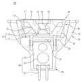
도 1은 본 발명의 일 실시예에 따른 LED 조명기구의 분해사시도를 도시한다.
도 2는 본 발명의 일 실시예에 따른 LED 조명기구의 측단면도를 도시한다.
도 3은 본 발명의 일 실시예에 따른 LED 조명기구의 렌즈유닛 및 방열부재의 측단면도를 도시한다.
도 4는 본 발명의 일 실시예에 따른 LED 조명기구의 렌즈유닛과 방열부재가 결합된 상태를 나타내는 요부 확대 단면도이다.
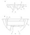
도 5는 본 발명의 다른 실시예에 따른 LED 조명기구의 렌즈유닛 및 방열부재의 측단면도를 도시한다.
도 6은 본 발명의 다른 실시예에 따른 LED 조명기구의 렌즈유닛과 방열부재가 결합된 상태를 나타내는 측단면도이다.
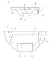
도 7은 본 발명의 또 다른 실시예에 따른 LED 조명기구의 렌즈유닛 및 방열부재의 측단면도를 도시한다.
도 8은 본 발명의 또 다른 실시예에 따른 LED 조명기구의 렌즈유닛과 방열부재가 결합된 상태를 나타내는 요부 확대 단면도이다.1 is an exploded perspective view of an LED lighting fixture according to an embodiment of the present invention.
2 shows a side cross-sectional view of an LED luminaire according to one embodiment of the invention.
3 is a side cross-sectional view of the lens unit and the heat dissipation member of the LED lighting device according to an embodiment of the present invention.
Figure 4 is an enlarged cross-sectional view of the main portion showing a state in which the lens unit and the heat dissipation member of the LED lighting apparatus according to an embodiment of the present invention is coupled.
5 is a side cross-sectional view of the lens unit and the heat dissipation member of the LED lighting device according to another embodiment of the present invention.
Figure 6 is a side cross-sectional view showing a state in which the lens unit and the heat dissipation member of the LED lighting apparatus according to another embodiment of the present invention.
7 is a side cross-sectional view of the lens unit and the heat dissipation member of the LED lighting device according to another embodiment of the present invention.
8 is an enlarged cross-sectional view illustrating main parts of a lens unit and a heat dissipation member of an LED lighting apparatus according to still another embodiment of the present invention;
이하, 첨부된 도면들을 참조하여 본 발명의 바람직한 실시예들을 상세히 설명하기로 한다. 그러나, 본 발명은 여기서 설명된 실시예들에 한정되지 않고 다른 형태로 구체화될 수도 있다. 오히려, 여기서 소개되는 실시예들은 개시된 내용이 철저하고 완전해질 수 있도록, 그리고 당업자에게 본 발명의 사상이 충분히 전달될 수 있도록 하기 위해 제공되는 것이다. 명세서 전체에 걸쳐서 동일한 참조번호들은 동일한 구성요소들을 나타낸다.Hereinafter, preferred embodiments of the present invention will be described in detail with reference to the accompanying drawings. However, the present invention is not limited to the embodiments described herein but may be embodied in other forms. Rather, the embodiments disclosed herein are provided so that the disclosure can be thorough and complete, and will fully convey the scope of the invention to those skilled in the art. Like numbers refer to like elements throughout.
본 발명에 따른 LED 조명기구는 LED(Light Emitting Diode, 발광 다이오드)를 조명의 용도로 사용하는 모든 종류의 조명기구에 적용될 수 있다. 즉, 본 발명에 따른 LED 조명기구는 LED가 사용되는 가로등, 램프, 다운라이트, 평판조명, 튜브형 조명, 간판/실내외 인테리어 조명, 라이트바 등 모든 종류에 적용될 수 있다.The LED luminaire according to the present invention can be applied to all kinds of luminaires using LEDs (Light Emitting Diodes). That is, the LED lighting apparatus according to the present invention can be applied to all kinds of street lamps, lamps, downlights, flat panel lighting, tubular lighting, signboards, indoor / outdoor interior lighting, light bars, etc., in which LEDs are used.
이하에서는 설명의 간명함을 위해 상기와 같은 여러 종류의 LED 조명기구 중 램프형 조명기구, 즉 LED 램프를 예로 들어 설명한다.Hereinafter, for clarity of explanation, a lamp-type lighting device, ie, an LED lamp, will be described as an example among the above-described various types of LED lighting devices.
도 1은 본 발명의 일 실시예에 따른 LED 조명기구의 분해사시도를 도시한다.1 is an exploded perspective view of an LED lighting fixture according to an embodiment of the present invention.
도 1에 도시된 바와 같이, 본 발명의 일 실시예에 따른 LED 조명기구(100)는 LED 소자(11)를 포함하는 광원부(10), 광원부(10)가 배치되어 LED 소자(11)로부터 발생되는 열을 방출시키며 개구부(31)가 구비되는 방열부재(30), 상기 방열부재(30)의 개구부(31)에 구비되는 렌즈유닛(50) 및 상기 렌즈유닛(50)과 방열부재(30)의 결합을 위해 렌즈유닛(50) 및 방열부재(30)에 각각 일체로 형성되는 체결부재(70; 71A,73A)를 포함할 수 있다.As shown in FIG. 1, the
광원부(10)는 적어도 1개 이상의 LED 소자(11)와 상기 LED 소자(11)가 장착되는 인쇄회로기판(13)으로 이루어질 수 있다. 여기서 인쇄회로기판(13)에는 광원부(10)를 방열부재(30)에 장착시키는 적어도 1개 이상의 고정부재(20)가 삽입 관통되기 위한 적어도 1개 이상의 관통홀(21)이 형성될 수 있다. 상기 고정부재(20)는 도 1에 도시된 바와 같이, 볼트일 수 있다.The
방열부재(30)의 내부에는 개구부(31)를 상부(31-1, 도 3 참조)와 하부(31-2, 도 3 참조)로 구분하는 안착면(33, 도 2 참조)이 구비될 수 있다.The
상기 광원부(10)는 방열부재(30)의 안착면(33) 상에 거치된 상태에서 상기 고정부재(20)가 광원부(10)에 형성된 관통홀(21) 및 안착면(33)에 형성된 관통홀(미도시)을 관통함으로써 방열부재(30)에 고정될 수 있다.The
즉, 광원부(10)는 방열부재의 개구부(31)의 상부(31-1)에 위치하여 방열부재(30)의 상부를 향해 빛을 조사할 수 있다.That is, the
상기 방열부재(30)는 광원부(10)의 LED 소자(11)가 발광할 때 발생하는 다량의 열을 대기 중으로 방출시켜 방열 역할을 하는 것으로서, 히트싱크(heat sink)라고도 한다.The
도 1에 도시된 방열부재(30)는 수평방향으로 자른 단면이 원형이 되며, 그 단면은 하부에서 상부로 갈수록 커지도록 형성되어 있으나, 본 발명에 따른 방열부재는 이와 같은 형상에 한정되지 않는다.The
방열부재(30)는 상기 광원부(10) 및 후술할 전장부(60)와 베이스(80)를 그 내부에 수용할 수 있도록 내부에 개구부(31)를 구비하는 것이 바람직하다.The
방열부재(30)의 내부에는 상기 개구부(31)를 상부와 하부로 구분하는 안착면이 구비되어 상기 안착면 상에 광원부(10)에 고정될 수 있는데, 이에 대해서는 후술한다.The inside of the
방열부재(30)는 LED 소자(11)로부터 발생하는 열을 신속히 전달시켜 외부로 방출하기 위해 금속재질로 이루어질 수 있다. 다만, 방열부재(30)의 중량화를 방지하기 위해 알루미늄 등의 가벼운 재질로 이루어지는 것이 바람직하다. 또는, 상기 방열부재(30)는 열전도성 플라스틱 재질로 형성될 수도 있다.The
한편, 방열부재(30)의 외부에는 미리 결정된 간격으로 방사상으로 이격된 복수 개의 방열핀(35)이 구비되는 것이 바람직하다.On the other hand, the outside of the
이와 같이 방열핀(35)을 복수 개 구비하면 공기와의 접촉면적이 넓어지므로 효과적인 방열이 가능하다. 또한, 방열핀(35)을 서로 일정간격 이격시켜 위치시킴으로써 방열핀(35)과 이웃하는 방열핀(35) 사이로 공기가 용이하게 유동할 수 있게 되어 방열성능이 향상된다.In this way, when a plurality of
본 발명에 따른 렌즈유닛(50)은 방열부재(30)의 개구부(31)에 구비되어, 상기 광원부(10)의 LED 소자(11)로부터 조사되는 빛을 수집 포획하고 특정 방향으로 빛을 디렉팅(directing)한다. 구체적으로 렌즈유닛(50)은 상기 광원부(10)의 상부, 방열부재(30)의 개구부의 상부(31-1)에 구비될 수 있다.The
본 실시예의 렌즈유닛(50)은 집광렌즈(51), 플랜지부(53), 광출사부(55) 및 체결가이드부(57)를 포함하여 이루어질 수 있다. 렌즈유닛(50)에 대한 보다 자세한 설명은 도 2 이하를 참조하여 후술하기로 한다.The
본 발명에 따른 LED 조명기구(100)는 반사부재(40)를 더 포함할 수 있다. 반사부재(40)는 광원부(10)와 렌즈유닛(50) 사이에 구비될 수 있다. 반사부재(40)는 LED 소자(11)로부터 조사되는 빛 중 렌즈유닛(50)으로 입사되지 않고 빠져나가는 빛을 다시 렌즈유닛(50) 내부로 입사시키는 역할을 수행한다.
한편, 본 발명에 따른 LED 조명기구(100)는 전장부(60)를 더 포함할 수 있다. 전장부(60)는 방열부재(30)의 하부, 구체적으로는 방열부재(30)의 개구부의 하부(31-2)에 구비될 수 있다.On the other hand,
전장부(60)는 외부로부터 전원을 공급받기 위한 전원커넥터(61), 외부로부터 전원커넥터(61)를 통해 유입된 전원을 광원부(10)에 공급하고 LED 소자(11)의 작동을 제어하는 제어소자(63), 상기 전원커넥터(61) 및 제어소자(63)가 장착되는 제어기판(65)을 포함할 수 있다.
여기서 상기 제어소자(63) 및 제어소자(63)가 실장된 제어기판(65)은 방열부재(30)의 내부에 위치함으로써 차폐되는 것이 바람직하다. 이와 달리 상기 전원커넥터(61)는 외부전원과의 접속을 위해 방열부재(30)의 외부로 노출되는 것이 바람직하다.Here, the
본 발명에 따른 LED 조명기구(100)는 베이스(80)를 더 포함할 수 있다. 베이스(80)는 방열부재(30)의 하부에 구비될 수 있다. 베이스(80)는 상기 전장부(60)를 그 내부에 고정시켜 상기 방열부재(30)의 내부로 삽입시키며, LED 소자(11)로부터 발생하여 방열부재(30)로 전달되는 열이 전장부(60)에 직접 전달되는 것을 방지할 수 있다.
즉, 베이스(80)의 일부는 전장부(60)를 내부에 고정하고 방열부재(30) 내부에 끼워맞춤됨으로써 방열부재(30)에 의해 차폐될 수 있다. 베이스(80)의 또 다른 일부는 방열부재(30)의 외부로 노출되며, 전장부의 전원커넥터(61)가 외부로 노출될 수 있도록 전원커넥터홀(미도시)이 그 저면에 형성될 수 있다.That is, a part of the base 80 may be shielded by the
도 2는 본 발명의 일 실시예에 따른 LED 조명기구의 측단면도를 도시한다.2 shows a side cross-sectional view of an LED luminaire according to one embodiment of the invention.
도 2에 도시된 바와 같이, 광원부(10)는 방열부재(30)의 내부에 형성되어 방열부재(30)의 개구부를 상하로 구분하는 안착면(33) 상에 장착될 수 있다. 광원부(10)는 볼트 등의 고정부재(20)가 관통홀(21) 및 안착면(33)의 관통홀(미도시)을 관통하여 체결됨으로써 안착면(33)에 견고하게 고정될 수 있다.As shown in FIG. 2, the
방열부재(30)의 개구부의 하부에는 전장부(60)가 고정된 베이스(80)의 일부가 삽입되어 고정된다. 전장부(60)와 방열부재(30) 사이에는 베이스(80)가 개재됨으로써 전장부(60)는 전기적, 열적으로 방열부재(30)의 영향을 받지 않는다.A portion of the base 80 to which the
이하에서는 LED 소자(11)로부터 제공되는 빛이 렌즈유닛(50)을 통해 조사되는 과정을 설명한다.Hereinafter, a process in which light provided from the
상기 렌즈유닛(50)은 광원부(10)의 LED 소자(11)에 의해 방사되는 빛을 포획하고 리디렉팅(redirect)한다. 렌즈유닛(50)은 LED 소자(11)에 의해 방출되는 빛의 대부분을 포획하도록 집광렌즈(51)를 포함할 수 있다. 집광렌즈(51)의 반사 표면은 일반적으로 원뿔, 즉, 포물선, 타원, 또는 쌍곡선으로부터 도출되는 원뿔일 수 있다.The
도 2를 참조하면, 집광렌즈(51)는 LED 소자(11)에 의해 방출되는 빛을 집광하고, 빛이 광출사부(55)에서 렌즈유닛(50)을 빠져나가도록 빛을 디렉팅(directing)한다.Referring to FIG. 2, the
빛의 일부는, LED 소자(11)로부터 1차 옵틱(primary optic)(52)을 통과하여, 집광렌즈(51) 내부에 형성된 제1 캐비티(cavity)(54) 내부로 이동한다. 그리고, 제1 캐비티(54) 상부에 구비된 중앙 위치 렌즈(56)를 통과하여, 광출사부(55)를 통해 나간다.Some of the light passes from the
중앙 위치 렌즈(56)를 통과하지 못한 빛은 집광렌즈(51)의 내부 측벽으로 굴절되며 입사된다. 그 후, 집광렌즈(51) 내부로 입사된 빛은 집광렌즈(51) 외부의 반사 표면에서 반사된다. 반사된 빛은 렌즈유닛(50)의 몸체에서 대기로 이동함에 따라 광출사부(55)에서 다시 굴절된다. 도 2에 도시된 바와 같이, 집광렌즈(51) 외부의 반사 표면은 집광렌즈(51)의 단면 프로파일(cross-sectional profile)이 반사 표면에서 포물선이 되도록 원뿔꼴이다.Light that does not pass through the
한편, 상기 렌즈유닛(50)은 방열부재(30)에서 렌즈유닛(50)을 유지하기 위해 구비되는 플랜지부(53) 및 플랜지부(53) 하부에 구비되며 렌즈유닛(50)과 방열부재(30)의 결합을 보조하는 체결가이드부(57)를 포함할 수 있다.On the other hand, the
또한, 본 발명의 일 실시예에 따른 LED 조명기구(100)는 체결가이드부(57) 및 방열부재(30)의 일측에 구비되는 체결부재(70)를 포함할 수 있다. 이에 대해서는 도 3 이하를 참조하여 자세히 설명하기로 한다.In addition, the
도 3은 본 발명의 일 실시예에 따른 LED 조명기구의 렌즈유닛 및 방열부재의 측단면도를 도시한다. 보다 상세하게는, 도 3(a)는 본 발명의 일 실시예에 따른 렌즈유닛(50)의 측단면도를, 도 3(b)는 본 발명의 일 실시예에 따른 방열부재(30)의 측단면도를 각각 도시한다.3 is a side cross-sectional view of the lens unit and the heat dissipation member of the LED lighting device according to an embodiment of the present invention. More specifically, Figure 3 (a) is a side cross-sectional view of the
도 3에 도시된 바와 같이, 본 발명의 일 실시예에 따른 LED 조명기구는 렌즈유닛(50)과 방열부재(30)의 결합을 위해 렌즈유닛(50) 및 방열부재(30)에 각각 일체로 형성되는 체결부재(71A, 73A)를 포함할 수 있다.As shown in FIG. 3, the LED lighting device according to the embodiment of the present invention is integrally formed with the
보다 구체적으로, 상기 체결부재(71A, 73A)는 렌즈유닛(50) 및 방열부재(30)의 일측에 형성되는 나사산일 수 있다. 이와 같이, 나사산을 렌즈유닛(50)과 방열부재(30)의 일측에 각각 형성함으로써 볼트와 같은 별도의 체결구를 사용하지 않고 간단하게 렌즈유닛(50)과 방열부재(30)를 결합시킬 수 있다.More specifically, the
도 3(a)에 도시된 바와 같이, 본 발명의 일 실시예에 따른 렌즈유닛(50)은 집광렌즈(51), 상기 집광렌즈(51)의 상부에 구비되는 플랜지부(53), 상기 플랜지부(53)의 상부에 구비되는 광출사부(55) 및 상기 플랜지부(53)의 하부와 방열부재(30) 사이에 구비되는 체결가이드부(57)를 포함하여 이루어질 수 있다.As shown in Figure 3 (a), the
전술한 바와 같이, 집광렌즈(51)는 광원부(10, 도 1 및 도 2 참조)로부터 방출되는 빛을 포획하고, 이를 광출사부(55)로 출사시킨다.As described above, the
집광렌즈(51)의 상부에 구비되는 플랜지부(53)는 방열부재(30)에서 렌즈유닛(50)을 유지하기 위한 것으로서, 구체적으로는 도 3(b)에 도시된 방열부재(30)의 개구부(31)에 형성되는 단차부(37)에 안착됨으로써 지지된다.The
체결가이드부(57)는 렌즈유닛(50)과 방열부재(30)의 결합을 보조하기 위해 구비되는 것으로서, 플랜지부(53)의 하부에 구비될 수 있다.The
구체적으로는, 플랜지부(53)의 하부의 가장자리로부터 미리 결정된 간격으로 내측으로 이격되는 위치에 형성될 수 있다. 체결가이드부(57)는 플랜지부(53)의 하부로부터 하방을 향하여 일정 길이만큼 돌출되어 형성될 수 있다. 또한, 체결가이드부(57)는 플랜지부(53)의 둘레방향을 따라 연장형성되어 띠 형상으로 구비될 수 있다(도 1 참조). 그러나, 이러한 형상에 국한되는 것은 아니며, 체결가이드부는 플랜지부(53)의 둘레방향을 따라 미리 결정된 간격으로 이격되어 복수 개 형성될 수 있다.Specifically, it may be formed at a position spaced inward at a predetermined interval from the edge of the lower portion of the
체결가이드부(57)는 방열부재(30)의 개구부(31)로 렌즈유닛(50)을 장착할 때 방열부재(30)의 단차부(37) 하측으로 연장되는 내측면에 접촉되어 렌즈유닛(50) 고정위치를 가이드할 수 있다.The
상기 체결가이드부(57)는 플랜지부(53)로부터 일체로 연장되어 구비되는 것이 바람직하다.The
도 3(b)를 참조하면, 방열부재(30)는 외부에 방사상으로 서로 이격되어 형성된 복수 개의 방열핀(35)을 구비하고, 내부에는 개구부(31)가 형성된다. 상기 개구부(31)에는 개구부를 상부(31-1)와 하부(31-2)로 구분하는 안착면(33)이 형성될 수 있다.Referring to FIG. 3B, the
방열부재(30)의 개구된 상측에서 하방으로 소정 간격 이격된 위치에는 렌즈유닛(50)의 플랜지부(53)가 지지되기 위한 단차부(37)가 내측을 향해 연장형성될 수 있다.A
여기서, 상기 체결부재(71A, 73A)는 렌즈유닛(50)의 체결가이드부(57) 및 방열부재(30)의 일측에 각각 형성될 수 있다.Here, the
도 3에 도시된 실시예에서 상기 체결부재(71A, 73A)는 체결가이드부(57)의 외측 및 방열부재(30)의 개구부(31)의 내측에 형성된다.In the embodiment shown in FIG. 3, the
구체적으로, 체결부재(71A)는 체결가이드부(57)의 외주면에 형성되는 나사산이며, 체결부재(73A)는 방열부재(30)의 단차부(37)로부터 하방으로 연장된 개구부(31)의 내주면에 형성되는 나사산이다.Specifically, the
상기 체결부재(71A)와 체결부재(73A)는 서로 대응되는 위치에 형성될 수 있다. 구체적으로는 체결부재(71A)의 하부가 체결부재(73A)의 상부에 결합되기 시작할 때부터 렌즈유닛(50)의 플랜지부(53)가 방열부재(30)의 단차부(37)에 안착될 때까지 서로 대응되도록 형성된다.The
도 4는 본 발명의 일 실시예에 따른 LED 조명기구의 렌즈유닛과 방열부재가 결합된 상태를 나타내는 요부 확대 단면도이다. 도 4는 렌즈유닛(50)과 방열부재(30) 이외에 반사부재(40)가 더 포함된 상태를 도시한다.Figure 4 is an enlarged cross-sectional view of the main portion showing a state in which the lens unit and the heat dissipation member of the LED lighting apparatus according to an embodiment of the present invention is coupled. 4 illustrates a state in which the
도 4에 도시된 바와 같이, 렌즈유닛(50)의 체결가이드부(57)에 형성된 체결부재(71A)는 방열부재(30)의 개구부의 상부(31-1)에 형성된 체결부재(73A)에 나사결합될 수 있다. 이와 같은 나사결합에 의해 렌즈유닛(50)은 방열부재(30)에 고정된다.As shown in FIG. 4, the
체결부재(70) 간 결합은 렌즈유닛(50)의 체결부재(71A)의 하단과 방열부재(30)의 체결부재(73A)의 상단이 맞물릴 때부터, 렌즈유닛(50)의 플랜지부(53)가 방열부재(30)의 단차부(37)에 안착될 때까지 이루어진다. 또는 렌즈유닛(50)의 체결가이드부(57)의 하단이 반사판(40)에 접촉될 때 결합이 종료된다.The coupling between the
즉, 플랜지부(53)와 단차부(37) 또는 체결가이드부(57)와 반사판(40)은 렌즈유닛(50)과 방열부재(30)의 결합을 종료시키는 스토퍼 역할을 수행할 수 있다.That is, the
이와 같이 본 발명에 따른 체결부재(70)는 렌즈유닛(50)과 방열부재(30)의 일측에 일체로 형성된 나사산이므로, 볼트 등과 같이 렌즈유닛(50)을 방열부재(30)에 체결하기 위한 별도의 기구물이 필요하지 않다. 즉, 양산성이 향상될 수 있다.As described above, since the
또한 볼팅(bolting) 작업 없이 렌즈유닛(50)의 체결가이드부(57)을 이용하여 렌즈유닛(50)의 일단을 방열부재(30)에 삽입한 후 렌즈유닛(50)을 회전시키는 것만으로 방열부재(30)와 렌즈유닛(50)을 결합시킬 수 있으므로, 조립성이 향상될 수 있다.In addition, after inserting one end of the
나아가, 볼트를 사용하는 경우와 달리 외부에서 체결부재(70)가 관찰되지 않으므로 외부 형상이 단순화될 수 있다. 즉, 디자인 특성이 강화된다.Furthermore, unlike the case where the bolt is used, since the
이하에서는 도 5 및 도 6을 참조하여 본 발명의 다른 실시예에 따른 LED 조명기구에 대해 설명한다. 편의상, 도 1 내지 도 4에 도시된 실시예와 중복되는 부분에 대해서는 설명을 생략한다.Hereinafter, an LED lighting device according to another embodiment of the present invention will be described with reference to FIGS. 5 and 6. For convenience, description of parts overlapping with the embodiments shown in FIGS. 1 to 4 will be omitted.
도 5는 본 발명의 다른 실시예에 따른 LED 조명기구의 렌즈유닛 및 방열부재의 측단면도를 도시한다. 보다 상세하게는, 도 5(a)는 본 발명의 다른 실시예에 따른 렌즈유닛(50)의 측단면도를, 도 3(b)는 본 발명의 다른 실시예에 따른 방열부재(30)의 측단면도를 각각 도시한다.5 is a side cross-sectional view of the lens unit and the heat dissipation member of the LED lighting device according to another embodiment of the present invention. More specifically, Figure 5 (a) is a side cross-sectional view of the
도 5에 도시된 바와 같이, 본 실시예에 따른 렌즈유닛(50)은 집광렌즈(51), 상기 집광렌즈(51)의 상부에 구비되는 플랜지부(53) 및 상기 플랜지부(53)의 상부에 구비되는 광출사부(55)를 포함하여 이루어지고, 체결부재(70; 71B,73B)는 상기 플랜지부(53)의 외측 및 방열부재(30)의 개구부(31)의 내측에 형성된다.As shown in FIG. 5, the
본 실시예의 렌즈유닛(50)이 도 3에 도시된 실시예와 다른 점은 체결부재(71B)가 플랜지부(53)의 외측에 직접 구비된다는 점이다. 따라서 본 실시예의 렌즈유닛(50)에는 도 1 내지 도 4에 도시된 실시예와 같은 체결가이드부(57)가 생략된다.The
다만, 본 실시예에 따른 렌즈유닛(50)에는 방열부재(30)에 렌즈유닛(50)을 체결할 때 체결깊이를 제한하기 위해 스토퍼(90)가 더 구비된다.However, the
즉, 상기 렌즈유닛(50)은 집광렌즈(51), 상기 집광렌즈(51)의 상부에 구비되는 플랜지부(53), 상기 플랜지부(53)의 상부에 구비되는 광출사부(55) 및 상기 집광렌즈(51)의 하부에 구비되어 렌즈유닛의 결합위치를 제한하는 스토퍼(90)를 포함하여 이루어질 수 있다.That is, the
상기 스토퍼(90)는 양산성의 강화를 위해 집광렌즈(51)로부터 연장 형성되는 것이 바람직하다.The
상기 스토퍼(90)는 집광렌즈(51)의 하부 둘레를 따라 원통 형상으로 형성될 수도 있고, 집광렌즈(51)의 하부 둘레를 따라 미리 결정된 간격으로 이격되어 복수 개가 형성될 수도 있다.The
한편, 도 5(b)에 도시된 바와 같이, 본 실시예에 따른 방열부재(30)에는 렌즈유닛(50)의 플랜지부(53)에 구비되는 체결부재(71B)와 대응되는 위치에 체결부재(73B)가 구비된다.On the other hand, as shown in Figure 5 (b), the
즉, 도 3에 도시된 실시예에서 방열부재(30)의 체결부재(73A)는 단차부(37)로부터 하방으로 연장된 개구부(31)의 내면에 형성되었으나, 본 실시예의 체결부재(73B)는 단차부(37)의 타단으로부터 상방으로 연장되는 개구부(31)의 내면에 형성된다.That is, in the embodiment shown in FIG. 3, the
도 6은 본 발명의 다른 실시예에 따른 LED 조명기구의 렌즈유닛과 방열부재가 결합된 상태를 나타내는 측단면도이다.Figure 6 is a side cross-sectional view showing a state in which the lens unit and the heat dissipation member of the LED lighting apparatus according to another embodiment of the present invention.
도 6에 도시된 바와 같이, 렌즈유닛(50)에 구비된 체결부재(71B, 도 5 참조)는 방열부재(30)에 구비된 체결부재(73B, 도 5 참조)와 나사결합됨으로써 렌즈유닛(50)과 방열부재(30)를 결합 고정시킨다.As shown in FIG. 6, the
여기서, 렌즈유닛(50)과 방열부재(30)의 결합은 스토퍼(90)의 일단이 광원부(10)의 인쇄회로기판(13)에 접촉됨으로써 종료된다. 즉, 스토퍼(90)는 렌즈유닛(50)의 결합위치를 제한할 수 있다. 이를 위해, 스토퍼(90)의 길이는 렌즈유닛(50)의 플랜지부(53)가 방열부재(30)의 단차부(37)에 안착될 때 스토퍼(90)의 일단이 인쇄회로기판(13)에 접촉될 수 있는 정도의 길이를 갖는 것이 바람직하다.Here, the coupling between the
이하에서는 도 7 및 도 8을 참조하여 본 발명의 또 다른 실시예에 따른 LED 조명기구에 대해 설명한다. 편의상, 앞서 설명된 실시예와 중복되는 부분에 대해서는 설명을 생략한다.Hereinafter, with reference to FIGS. 7 and 8 will be described with respect to the LED lighting fixture according to another embodiment of the present invention. For convenience, description of parts overlapping with the above-described embodiment will be omitted.
도 7은 본 발명의 또 다른 실시예에 따른 LED 조명기구의 렌즈유닛 및 방열부재의 측단면도를 도시한다. 보다 상세하게는, 도 7(a)는 본 발명의 또 다른 실시예에 따른 렌즈유닛(50)의 측단면도를, 도 7(b)는 본 발명의 또 다른 실시예에 따른 방열부재(30)의 측단면도를 각각 도시한다.7 is a side cross-sectional view of the lens unit and the heat dissipation member of the LED lighting device according to another embodiment of the present invention. More specifically, Figure 7 (a) is a side cross-sectional view of the
도 7에 도시된 바와 같이, 본 실시예에 따른 체결부재(70)는 렌즈유닛(50)의 일측에 형성되는 후크(71C) 및 방열부재(30)의 일측에 형성되는 결합홈(73C)이다.As shown in FIG. 7, the
구체적으로, 본 실시예에 따른 렌즈유닛(50)은 집광렌즈(51), 상기 집광렌즈(51)의 상부에 구비되는 플랜지부(53), 상기 플랜지부(53)의 상부에 구비되는 광출사부(55) 및 상기 플랜지부(53)의 하부와 방열부재(30) 사이에 구비되는 체결가이드부(57)를 포함하여 이루어지고, 상기 후크(71C)는 체결가이드부(57)에 형성될 수 있다.In detail, the
본 실시예에 따른 렌즈유닛(50)은 도 1 내지 도 4에 도시된 실시예와 같이 체결가이드부(57)를 구비하므로 렌즈유닛(50)을 방열부재(30)에 삽입할 때 체결가이드부(57)가 삽입위치를 가이드해줄 수 있다. 다만, 본 실시예에 따른 렌즈유닛(50)은 도 1 내지 도 4에 도시된 실시예와 달리, 렌즈유닛(50)에 일체로 형성된 체결부재(70)로서 나사산 대신 후크(71C)를 채용한다.Since the
상기 후크(71C)는 체결가이드부(57)의 단부로부터 외부를 향하도록 연장 형성될 수 있다.The
도 7(b)에 도시된 바와 같이, 방열부재(30)의 내부에는 렌즈유닛(50)에 일체로 형성된 후크(71C)가 걸리기 위한 결합홈(73C)이 일체로 형성될 수 있다. 보다 구체적으로, 상기 결합홈(73C)은 방열부재(30)의 개구부, 특히 개구부의 상부(31-1)의 내측면에서 요입되어 형성될 수 있다.As shown in FIG. 7B, the
렌즈유닛(50)의 플랜지부(53)가 방열부재(30)의 단차부(37)에 안착될 때 상기 후크(71C)가 결합홈(73C)에 걸릴 수 있도록, 결합홈(73C)은 후크(71C)에 대응되는 위치에 형성되는 것이 바람직하다.When the
도 8은 본 발명의 또 다른 실시예에 따른 LED 조명기구의 렌즈유닛과 방열부재가 결합된 상태를 나타내는 요부 확대 단면도이다.8 is an enlarged cross-sectional view illustrating main parts of a lens unit and a heat dissipation member of an LED lighting apparatus according to still another embodiment of the present invention;
도 8에 도시된 바와 같이, 본 실시예에 따른 렌즈유닛(50)은 렌즈유닛(50)에 일체로 형성된 후크(71C)가 방열부재(30)에 일체로 형성된 결합홈(73C)에 걸림결합됨으로써 방열부재(30)에 고정될 수 있다.As shown in FIG. 8, in the
여기서, 후크(71C)가 결합홈(73C)에 걸린 상태에서 체결가이드부(57)는 방열부재(30)의 내면에 접촉되어 외부로 가압하는 방향으로 힘이 주어지는 것이 바람직하다. 즉, 렌즈유닛(50)을 방열부재(30)에 삽입할 때 억지끼움될 수 있도록 체결가이드부(57)의 형성위치는 방열부재(30)의 내면보다 약간 외측에 형성되는 것이 바람직하다.Here, it is preferable that the
이와 같이, 본 실시예에 따른 LED 조명기구에서는 렌즈유닛(50)을 방열부재(30)의 개구부(31)로 밀어넣는 것만으로 방열부재(30)에 렌즈유닛(50)을 결합시킬 수 있으므로, 조립성 및 양산성이 향상된다.As such, in the LED lighting device according to the present embodiment, the
또한 외부로부터 체결부재(70)가 관찰되지 않으므로 디자인 특성이 강화될 수 있다.In addition, since the
10 : 광원부11 : LED 소자
13 : LED 소자30 : 방열부재
31 : 개구부40 : 반사부재
50 : 렌즈유닛51 : 집광렌즈
53 : 플랜지부55 : 광출사부
60 : 전장부70 : 체결부재
80 : 베이스10
13: LED element 30: heat radiating member
31: opening 40: reflective member
50
53
60: total length 70: fastening member
80: Base
Claims (11)
Translated fromKorean상기 광원부가 배치되어 상기 LED 소자로부터 발생되는 열을 방출시키며, 개구부가 구비되는 방열부재;
상기 방열부재의 개구부에 구비되는 렌즈유닛; 및,
상기 렌즈유닛과 상기 방열부재의 결합을 위해 상기 렌즈유닛 및 상기 방열부재에 각각 형성되는 체결부재를 포함하고,
상기 체결부재는 상기 렌즈유닛 및 방열부재의 일측에 각각 형성되는 나사산이며,
상기 렌즈유닛은 집광렌즈, 상기 집광렌즈의 상부에 구비되는 플랜지부 및 상기 플랜지부의 상부에 구비되는 광출사부를 포함하여 이루어지고,
상기 나사산은 상기 플랜지부의 외측 및 상기 개구부의 내측에 각각 형성되는 것을 특징으로 하는 LED 조명기구.A light source unit including an LED element;
A heat dissipation member in which the light source unit is disposed to emit heat generated from the LED element, and an opening is provided;
A lens unit provided in the opening of the heat dissipation member; And
It includes a fastening member formed on the lens unit and the heat dissipation member for coupling the lens unit and the heat dissipation member,
The fastening member is a screw thread formed on one side of the lens unit and the heat dissipation member,
The lens unit includes a condenser lens, a flange portion provided on the upper portion of the condenser lens, and a light emitting portion provided on the upper portion of the flange portion,
The screw thread is formed on the outer side of the flange portion and the inner side of the opening, respectively.
상기 렌즈유닛은 상기 집광렌즈의 하부에 구비되어 상기 렌즈유닛의 결합위치를 제한하는 스토퍼를 포함하여 이루어지는 것을 특징으로 하는 LED 조명기구.The method of claim 1,
The lens unit is provided in the lower portion of the condensing lens LED lighting device, characterized in that it comprises a stopper for limiting the coupling position of the lens unit.
상기 스토퍼는 상기 집광렌즈로부터 연장 형성되는 것을 특징으로 하는 LED 조명기구.The method according to claim 6,
The stopper is an LED luminaire, characterized in that formed extending from the condensing lens.
상기 광원부가 배치되어 상기 LED 소자로부터 발생되는 열을 방출시키며, 개구부가 구비되는 방열부재;
상기 방열부재의 개구부에 구비되는 렌즈유닛; 및,
상기 렌즈유닛과 상기 방열부재의 결합을 위해 상기 렌즈유닛 및 상기 방열부재에 각각 형성되는 체결부재를 포함하며,
상기 체결부재는 상기 렌즈유닛의 일측에 형성되는 후크 및 상기 방열부재의 일측에 형성되는 결합홈이고,
상기 렌즈유닛은 집광렌즈, 상기 집광렌즈의 상부에 구비되는 플랜지부, 상기 플랜지부의 상부에 구비되는 광출사부 및 상기 플랜지부의 하부와 상기 방열부재 사이에 구비되는 체결가이드부를 포함하여 이루어지며,
상기 후크는 상기 체결가이드부에 형성되는 것을 특징으로 하는 LED 조명기구.A light source unit including an LED element;
A heat dissipation member in which the light source unit is disposed to emit heat generated from the LED element, and an opening is provided;
A lens unit provided in the opening of the heat dissipation member; And
It includes a fastening member formed on the lens unit and the heat dissipation member for coupling the lens unit and the heat dissipation member,
The fastening member is a hook formed on one side of the lens unit and a coupling groove formed on one side of the heat dissipation member,
The lens unit includes a condenser lens, a flange portion provided on an upper portion of the condenser lens, a light output portion provided on an upper portion of the flange portion, and a fastening guide portion provided between a lower portion of the flange portion and the heat radiating member. ,
The hook is an LED luminaire, characterized in that formed on the fastening guide.
상기 결합홈은 상기 개구부의 내측면에서 요입되어 형성되는 것을 특징으로 하는 LED 조명기구.9. The method of claim 8,
LED luminaires, characterized in that the coupling groove is formed in the inner surface of the opening.
Priority Applications (3)
| Application Number | Priority Date | Filing Date | Title |
|---|---|---|---|
| KR1020100060168AKR101349841B1 (en) | 2010-06-24 | 2010-06-24 | LED lighting fixtures |
| US13/049,771US8157422B2 (en) | 2010-06-24 | 2011-03-16 | Lighting apparatus |
| US13/340,862US8303137B2 (en) | 2010-06-24 | 2011-12-30 | Lighting apparatus |
Applications Claiming Priority (1)
| Application Number | Priority Date | Filing Date | Title |
|---|---|---|---|
| KR1020100060168AKR101349841B1 (en) | 2010-06-24 | 2010-06-24 | LED lighting fixtures |
Publications (2)
| Publication Number | Publication Date |
|---|---|
| KR20110140007A KR20110140007A (en) | 2011-12-30 |
| KR101349841B1true KR101349841B1 (en) | 2014-01-09 |
Family
ID=45352414
Family Applications (1)
| Application Number | Title | Priority Date | Filing Date |
|---|---|---|---|
| KR1020100060168AExpired - Fee RelatedKR101349841B1 (en) | 2010-06-24 | 2010-06-24 | LED lighting fixtures |
Country Status (2)
| Country | Link |
|---|---|
| US (2) | US8157422B2 (en) |
| KR (1) | KR101349841B1 (en) |
Families Citing this family (85)
| Publication number | Priority date | Publication date | Assignee | Title |
|---|---|---|---|---|
| US7632004B2 (en)* | 2004-07-06 | 2009-12-15 | Tseng-Lu Chien | LED night light with more than 1 optics means |
| US8901829B2 (en)* | 2009-09-24 | 2014-12-02 | Cree Led Lighting Solutions, Inc. | Solid state lighting apparatus with configurable shunts |
| US9068719B2 (en)* | 2009-09-25 | 2015-06-30 | Cree, Inc. | Light engines for lighting devices |
| US9285103B2 (en)* | 2009-09-25 | 2016-03-15 | Cree, Inc. | Light engines for lighting devices |
| US8602579B2 (en)* | 2009-09-25 | 2013-12-10 | Cree, Inc. | Lighting devices including thermally conductive housings and related structures |
| US8777449B2 (en) | 2009-09-25 | 2014-07-15 | Cree, Inc. | Lighting devices comprising solid state light emitters |
| US8476836B2 (en) | 2010-05-07 | 2013-07-02 | Cree, Inc. | AC driven solid state lighting apparatus with LED string including switched segments |
| JP5175986B2 (en)* | 2010-06-02 | 2013-04-03 | パナソニック株式会社 | Lamp and lighting device |
| KR101216084B1 (en) | 2010-06-23 | 2012-12-26 | 엘지전자 주식회사 | Lighting device and module type lighting device |
| KR101053633B1 (en) | 2010-06-23 | 2011-08-03 | 엘지전자 주식회사 | Modular lighting |
| KR101349841B1 (en)* | 2010-06-24 | 2014-01-09 | 엘지전자 주식회사 | LED lighting fixtures |
| TW201200793A (en)* | 2010-06-29 | 2012-01-01 | Foxsemicon Integrated Tech Inc | Room illumination apparatus |
| KR101057064B1 (en)* | 2010-06-30 | 2011-08-16 | 엘지전자 주식회사 | LED lighting device and manufacturing method |
| CN103189684B (en)* | 2010-10-29 | 2016-08-17 | 欧司朗股份有限公司 | Light fixture |
| EP2803910B1 (en)* | 2010-11-30 | 2017-06-28 | LG Innotek Co., Ltd. | Lighting device |
| TWI414714B (en) | 2011-04-15 | 2013-11-11 | Lextar Electronics Corp | Light emitting diode cup light |
| CN102588762A (en)* | 2011-01-06 | 2012-07-18 | 隆达电子股份有限公司 | LED Cup Light |
| US9752769B2 (en) | 2011-01-12 | 2017-09-05 | Kenall Manufacturing Company | LED luminaire tertiary optic system |
| US8905589B2 (en) | 2011-01-12 | 2014-12-09 | Kenall Manufacturing Company | LED luminaire thermal management system |
| US10036544B1 (en) | 2011-02-11 | 2018-07-31 | Soraa, Inc. | Illumination source with reduced weight |
| US9839083B2 (en) | 2011-06-03 | 2017-12-05 | Cree, Inc. | Solid state lighting apparatus and circuits including LED segments configured for targeted spectral power distribution and methods of operating the same |
| US8742671B2 (en) | 2011-07-28 | 2014-06-03 | Cree, Inc. | Solid state lighting apparatus and methods using integrated driver circuitry |
| KR101227525B1 (en)* | 2011-08-12 | 2013-01-31 | 엘지전자 주식회사 | Lighting apparatus |
| KR20130022606A (en)* | 2011-08-25 | 2013-03-07 | 삼성전자주식회사 | Illuminating device |
| CN102269361A (en)* | 2011-08-26 | 2011-12-07 | 东莞泰德照明科技有限公司 | A modular LED lamp |
| CN107023762B (en)* | 2011-08-30 | 2020-12-11 | Lg伊诺特有限公司 | lighting device |
| US9488324B2 (en) | 2011-09-02 | 2016-11-08 | Soraa, Inc. | Accessories for LED lamp systems |
| US20130058099A1 (en)* | 2011-09-02 | 2013-03-07 | Soraa, Inc. | High Intensity Light Source with Interchangeable Optics |
| US20130077320A1 (en)* | 2011-09-23 | 2013-03-28 | Cooler Master Co., Ltd. | Optical lens and illuminant device using the same |
| KR101193113B1 (en)* | 2012-02-16 | 2012-10-19 | 권미숙 | A lamp assembly with led |
| CN102606945B (en)* | 2012-02-27 | 2013-11-27 | 中山伟强科技有限公司 | LED projection lamp |
| CN103363401B (en)* | 2012-03-02 | 2015-06-17 | 中山伟强科技有限公司 | LED projection lamp |
| KR101349513B1 (en)* | 2012-03-20 | 2014-01-09 | 엘지이노텍 주식회사 | Lighting apparatus and lighting system |
| US9091426B2 (en) | 2012-03-29 | 2015-07-28 | Abl Ip Holding Llc | Light assembly |
| CN103375765B (en)* | 2012-04-17 | 2017-07-21 | 欧司朗股份有限公司 | Lens unit and the lighting device including the lens unit |
| US8764251B2 (en)* | 2012-05-02 | 2014-07-01 | Everspring Industry Co., Ltd. | Heat dissipation structure for light bulb assembly |
| US8534875B1 (en)* | 2012-05-03 | 2013-09-17 | Shiyong Zhang | Customizable heat sink formed of sheet material for a lamp |
| US20140015438A1 (en)* | 2012-05-06 | 2014-01-16 | Lighting Science Group Corporation | Tunable light system and associated methods |
| US9006987B2 (en)* | 2012-05-07 | 2015-04-14 | Lighting Science Group, Inc. | Wall-mountable luminaire and associated systems and methods |
| US9360190B1 (en) | 2012-05-14 | 2016-06-07 | Soraa, Inc. | Compact lens for high intensity light source |
| US9995439B1 (en) | 2012-05-14 | 2018-06-12 | Soraa, Inc. | Glare reduced compact lens for high intensity light source |
| US10436422B1 (en) | 2012-05-14 | 2019-10-08 | Soraa, Inc. | Multi-function active accessories for LED lamps |
| CN103470966A (en)* | 2012-06-07 | 2013-12-25 | 欧司朗股份有限公司 | Lighting device |
| CN202955522U (en)* | 2012-06-28 | 2013-05-29 | 比亚迪股份有限公司 | A kind of LED lamp |
| KR101978633B1 (en)* | 2012-07-27 | 2019-05-15 | 엘지이노텍 주식회사 | Lighting device |
| USD684289S1 (en) | 2012-08-15 | 2013-06-11 | Cree, Inc. | Lighting fixture |
| US9140441B2 (en) | 2012-08-15 | 2015-09-22 | Cree, Inc. | LED downlight |
| USD684290S1 (en) | 2012-08-15 | 2013-06-11 | Cree, Inc. | Lighting fixture |
| USD684291S1 (en) | 2012-08-15 | 2013-06-11 | Cree, Inc. | Module on a lighting fixture |
| MX340847B (en) | 2012-08-20 | 2016-07-27 | Cooper Technologies Co | LIGHTING APPLICATIONS THAT USE ORGANIC DIODES EMISSING LIGHT. |
| CN103672467A (en)* | 2012-09-14 | 2014-03-26 | 欧司朗股份有限公司 | Lighting device |
| RU2659585C2 (en) | 2012-09-18 | 2018-07-03 | Филипс Лайтинг Холдинг Б.В. | Lamp with heat sink |
| DE202012103667U1 (en)* | 2012-09-25 | 2014-01-07 | Zumtobel Lighting Gmbh | Luminaire with contact protection |
| KR101432645B1 (en)* | 2012-10-09 | 2014-08-25 | 주식회사 대원이노스트 | Led bulb |
| US9215764B1 (en) | 2012-11-09 | 2015-12-15 | Soraa, Inc. | High-temperature ultra-low ripple multi-stage LED driver and LED control circuits |
| US9644830B2 (en)* | 2013-02-04 | 2017-05-09 | Sunlite Science & Technology, Inc. | Application-specific LED module and associated LED point source luminaires |
| CN105008788B (en)* | 2013-02-19 | 2019-02-19 | 飞利浦照明控股有限公司 | The lighting apparatus that hot attribute makes moderate progress |
| US9267661B1 (en) | 2013-03-01 | 2016-02-23 | Soraa, Inc. | Apportioning optical projection paths in an LED lamp |
| US9509146B2 (en) | 2013-03-05 | 2016-11-29 | Cooper Technologies Company | Inductive power transmission for electrical devices |
| US9435525B1 (en) | 2013-03-08 | 2016-09-06 | Soraa, Inc. | Multi-part heat exchanger for LED lamps |
| US20140268729A1 (en) | 2013-03-14 | 2014-09-18 | Lsi Industries, Inc. | Luminaires and luminaire mounting structures |
| US20140268821A1 (en)* | 2013-03-14 | 2014-09-18 | Lsi Industries, Inc. | Luminaires and luminaire mounting structures |
| US9441796B2 (en) | 2013-03-14 | 2016-09-13 | Lsi Industries, Inc. | Luminaire with long chains of lower power LEDs and multiple on-board LED drivers |
| KR101407194B1 (en)* | 2013-05-10 | 2014-06-12 | 현대오트론 주식회사 | Electronic control apparatus for vehicle |
| DE102014101403A1 (en)* | 2013-05-15 | 2014-11-20 | Seidel GmbH & Co. KG | lighting device |
| WO2014194024A1 (en)* | 2013-05-29 | 2014-12-04 | Venntis Technologies LLC | Light emitting device with heat sink |
| WO2014195876A1 (en)* | 2013-06-07 | 2014-12-11 | Koninklijke Philips N.V. | Lens and lighting device |
| KR102060790B1 (en)* | 2013-06-19 | 2019-12-31 | 삼성디스플레이 주식회사 | Optical structure and backlight unit |
| CN104456428A (en)* | 2013-09-12 | 2015-03-25 | 欧司朗有限公司 | Optical unit with light emitting structure, light emitting structure and light box with light emitting structure |
| CN103644536B (en)* | 2013-12-02 | 2017-04-05 | 广东凯西欧照明有限公司 | A kind of zooming LED lamp |
| US9680073B2 (en)* | 2014-05-30 | 2017-06-13 | Seoul Semiconductor Co., Ltd. | Light emitting module |
| US10209005B2 (en) | 2015-10-05 | 2019-02-19 | Sunlite Science & Technology, Inc. | UV LED systems and methods |
| TWI586918B (en)* | 2015-11-20 | 2017-06-11 | LED explosion-proof lamp cover | |
| DE102016203400A1 (en)* | 2016-03-02 | 2017-09-07 | Ledvance Gmbh | LIGHT MODULE |
| JP6765241B2 (en)* | 2016-07-13 | 2020-10-07 | 株式会社小糸製作所 | Lighting device for vehicles |
| JP2018056104A (en)* | 2016-09-29 | 2018-04-05 | 株式会社アブラム | Light-emitting diode type lighting device |
| KR200483780Y1 (en)* | 2016-12-19 | 2017-07-03 | 윤현중 | Signborad having a side light emitting unit |
| JP6716490B2 (en)* | 2017-01-20 | 2020-07-01 | サムジン エルエヌディー カンパニー リミテッドSamjin Lnd Co., Ltd | LED lighting fixture having natural convection type heat dissipation structure |
| US10584845B2 (en)* | 2017-05-12 | 2020-03-10 | Shoichi Nakamura | LED lighting apparatus |
| EP3447360A1 (en)* | 2017-08-24 | 2019-02-27 | Leedarson America Inc. | Led apparatus |
| EP3447359B1 (en)* | 2017-08-24 | 2023-08-16 | Leedarson America Inc. | Spotlight apparatus and manufacturing method thereof |
| US11073252B2 (en)* | 2019-03-26 | 2021-07-27 | Xiamen Eco Lighting Co. Ltd. | Light Bulb |
| CN113124329A (en)* | 2021-04-26 | 2021-07-16 | 贾万有 | Dual-purpose lamp for focusing and diffusing light |
| CN115047700B (en)* | 2022-05-30 | 2023-12-01 | 歌尔光学科技有限公司 | Projection ray apparatus |
| US20240401757A1 (en)* | 2023-06-05 | 2024-12-05 | Green Creative | Led lamp |
Citations (4)
| Publication number | Priority date | Publication date | Assignee | Title |
|---|---|---|---|---|
| KR200433632Y1 (en)* | 2006-09-28 | 2006-12-11 | 김기창 | Fountain lamp |
| KR20080079853A (en)* | 2007-02-28 | 2008-09-02 | 서울반도체 주식회사 | Light emitting diode with fastening structure |
| KR100910112B1 (en)* | 2008-10-09 | 2009-08-03 | 화우테크놀러지 주식회사 | Viewing angle extended LED lamp |
| KR100959910B1 (en)* | 2009-11-11 | 2010-06-01 | 우성전기주식회사 | LED board module |
Family Cites Families (6)
| Publication number | Priority date | Publication date | Assignee | Title |
|---|---|---|---|---|
| TWM310984U (en)* | 2006-11-28 | 2007-05-01 | Primo Lite Co Ltd | Lamp structure of light emitting diode |
| CN101368719B (en)* | 2007-08-13 | 2011-07-06 | 太一节能系统股份有限公司 | LED lamps |
| CN101451694B (en)* | 2007-12-07 | 2012-10-10 | 富准精密工业(深圳)有限公司 | LED lamp |
| US7677767B2 (en)* | 2008-04-01 | 2010-03-16 | Wen-Long Chyn | LED lamp having higher efficiency |
| US7922364B2 (en)* | 2009-03-10 | 2011-04-12 | Osram Sylvania, Inc. | LED lamp assembly |
| KR101349841B1 (en)* | 2010-06-24 | 2014-01-09 | 엘지전자 주식회사 | LED lighting fixtures |
- 2010
- 2010-06-24KRKR1020100060168Apatent/KR101349841B1/ennot_activeExpired - Fee Related
- 2011
- 2011-03-16USUS13/049,771patent/US8157422B2/ennot_activeExpired - Fee Related
- 2011-12-30USUS13/340,862patent/US8303137B2/ennot_activeExpired - Fee Related
Patent Citations (4)
| Publication number | Priority date | Publication date | Assignee | Title |
|---|---|---|---|---|
| KR200433632Y1 (en)* | 2006-09-28 | 2006-12-11 | 김기창 | Fountain lamp |
| KR20080079853A (en)* | 2007-02-28 | 2008-09-02 | 서울반도체 주식회사 | Light emitting diode with fastening structure |
| KR100910112B1 (en)* | 2008-10-09 | 2009-08-03 | 화우테크놀러지 주식회사 | Viewing angle extended LED lamp |
| KR100959910B1 (en)* | 2009-11-11 | 2010-06-01 | 우성전기주식회사 | LED board module |
Also Published As
| Publication number | Publication date |
|---|---|
| US20110317428A1 (en) | 2011-12-29 |
| KR20110140007A (en) | 2011-12-30 |
| US20120099313A1 (en) | 2012-04-26 |
| US8303137B2 (en) | 2012-11-06 |
| US8157422B2 (en) | 2012-04-17 |
Similar Documents
| Publication | Publication Date | Title |
|---|---|---|
| KR101349841B1 (en) | LED lighting fixtures | |
| KR101285889B1 (en) | LED lighting fixtures | |
| KR100926772B1 (en) | Ceiling recessed LED lighting | |
| KR100932192B1 (en) | LED luminaires with improved heat dissipation | |
| US10408425B2 (en) | Lighting device with socket connector positioning light source apart from housing | |
| KR101349843B1 (en) | Lighting apparatus | |
| US20130027947A1 (en) | Light emitting die (led) lamps, heat sinks and related methods | |
| KR101655740B1 (en) | LED lighting of one body type LED module case | |
| US20130039070A1 (en) | Lamp with front facing heat sink | |
| KR20220002223U (en) | Apparatus for lightening | |
| RU76418U1 (en) | LIGHT SOURCE | |
| US20130242566A1 (en) | Light emitting diode lamp | |
| CN202452202U (en) | Light-emitting device and lampshade thereof | |
| KR101270585B1 (en) | Mounting brakcet for lamp | |
| JP2012119230A (en) | Led lamp and led lighting device | |
| KR101676703B1 (en) | LED Shadowless Lamp Using Lens Direct Connecting Heat Sink | |
| KR20110139466A (en) | LED lighting fixture and manufacturing method | |
| KR200459074Y1 (en) | Light emitting diode lamp | |
| KR101961936B1 (en) | Light emitting diode lamp substitute for fluorescent light | |
| KR101020326B1 (en) | LED Fluorescent Tube | |
| KR101678045B1 (en) | LED lighting module for medical treatment | |
| KR101167043B1 (en) | Led light with multi-reflector | |
| JP5126637B2 (en) | lighting equipment | |
| KR100989035B1 (en) | LED buried lighting fixture | |
| CN215372235U (en) | Ceiling lamp free of screw installation |
Legal Events
| Date | Code | Title | Description |
|---|---|---|---|
| PA0109 | Patent application | St.27 status event code:A-0-1-A10-A12-nap-PA0109 | |
| P11-X000 | Amendment of application requested | St.27 status event code:A-2-2-P10-P11-nap-X000 | |
| P13-X000 | Application amended | St.27 status event code:A-2-2-P10-P13-nap-X000 | |
| PG1501 | Laying open of application | St.27 status event code:A-1-1-Q10-Q12-nap-PG1501 | |
| A201 | Request for examination | ||
| E13-X000 | Pre-grant limitation requested | St.27 status event code:A-2-3-E10-E13-lim-X000 | |
| P11-X000 | Amendment of application requested | St.27 status event code:A-2-2-P10-P11-nap-X000 | |
| P13-X000 | Application amended | St.27 status event code:A-2-2-P10-P13-nap-X000 | |
| PA0201 | Request for examination | St.27 status event code:A-1-2-D10-D11-exm-PA0201 | |
| D13-X000 | Search requested | St.27 status event code:A-1-2-D10-D13-srh-X000 | |
| D14-X000 | Search report completed | St.27 status event code:A-1-2-D10-D14-srh-X000 | |
| E902 | Notification of reason for refusal | ||
| PE0902 | Notice of grounds for rejection | St.27 status event code:A-1-2-D10-D21-exm-PE0902 | |
| E13-X000 | Pre-grant limitation requested | St.27 status event code:A-2-3-E10-E13-lim-X000 | |
| P11-X000 | Amendment of application requested | St.27 status event code:A-2-2-P10-P11-nap-X000 | |
| P13-X000 | Application amended | St.27 status event code:A-2-2-P10-P13-nap-X000 | |
| E701 | Decision to grant or registration of patent right | ||
| PE0701 | Decision of registration | St.27 status event code:A-1-2-D10-D22-exm-PE0701 | |
| GRNT | Written decision to grant | ||
| PR0701 | Registration of establishment | St.27 status event code:A-2-4-F10-F11-exm-PR0701 | |
| PR1002 | Payment of registration fee | St.27 status event code:A-2-2-U10-U11-oth-PR1002 Fee payment year number:1 | |
| PG1601 | Publication of registration | St.27 status event code:A-4-4-Q10-Q13-nap-PG1601 | |
| PN2301 | Change of applicant | St.27 status event code:A-5-5-R10-R13-asn-PN2301 St.27 status event code:A-5-5-R10-R11-asn-PN2301 | |
| FPAY | Annual fee payment | Payment date:20161214 Year of fee payment:4 | |
| PR1001 | Payment of annual fee | St.27 status event code:A-4-4-U10-U11-oth-PR1001 Fee payment year number:4 | |
| LAPS | Lapse due to unpaid annual fee | ||
| PC1903 | Unpaid annual fee | St.27 status event code:A-4-4-U10-U13-oth-PC1903 Not in force date:20180104 Payment event data comment text:Termination Category : DEFAULT_OF_REGISTRATION_FEE | |
| PC1903 | Unpaid annual fee | St.27 status event code:N-4-6-H10-H13-oth-PC1903 Ip right cessation event data comment text:Termination Category : DEFAULT_OF_REGISTRATION_FEE Not in force date:20180104 | |
| PN2301 | Change of applicant | St.27 status event code:A-5-5-R10-R13-asn-PN2301 St.27 status event code:A-5-5-R10-R11-asn-PN2301 |