KR101347343B1 - Automatic welding device for pipe - Google Patents
Automatic welding device for pipeDownload PDFInfo
- Publication number
- KR101347343B1 KR101347343B1KR1020120023913AKR20120023913AKR101347343B1KR 101347343 B1KR101347343 B1KR 101347343B1KR 1020120023913 AKR1020120023913 AKR 1020120023913AKR 20120023913 AKR20120023913 AKR 20120023913AKR 101347343 B1KR101347343 B1KR 101347343B1
- Authority
- KR
- South Korea
- Prior art keywords
- torch
- chain
- pipe
- welding device
- automatic welding
- Prior art date
- Legal status (The legal status is an assumption and is not a legal conclusion. Google has not performed a legal analysis and makes no representation as to the accuracy of the status listed.)
- Active
Links
- 238000003466weldingMethods0.000titleclaimsabstractdescription77
- 238000000034methodMethods0.000claimsdescription10
- 239000002184metalSubstances0.000claimsdescription8
- 229910052751metalInorganic materials0.000claimsdescription8
- 239000000498cooling waterSubstances0.000claimsdescription7
- 239000000835fiberSubstances0.000claimsdescription6
- 238000001816coolingMethods0.000claimsdescription5
- 238000009792diffusion processMethods0.000claimsdescription2
- 239000011810insulating materialSubstances0.000claimsdescription2
- 239000007921spraySubstances0.000abstract1
- 239000007789gasSubstances0.000description10
- 238000010586diagramMethods0.000description3
- 239000011261inert gasSubstances0.000description3
- 238000009941weavingMethods0.000description3
- XKRFYHLGVUSROY-UHFFFAOYSA-NArgonChemical compound[Ar]XKRFYHLGVUSROY-UHFFFAOYSA-N0.000description2
- 239000000463materialSubstances0.000description2
- 230000008569processEffects0.000description2
- WFKWXMTUELFFGS-UHFFFAOYSA-NtungstenChemical compound[W]WFKWXMTUELFFGS-UHFFFAOYSA-N0.000description2
- 239000010937tungstenSubstances0.000description2
- 229910052721tungstenInorganic materials0.000description2
- 229910052786argonInorganic materials0.000description1
- 239000010953base metalSubstances0.000description1
- 230000000903blocking effectEffects0.000description1
- 239000002657fibrous materialSubstances0.000description1
- 239000001307heliumSubstances0.000description1
- 229910052734heliumInorganic materials0.000description1
- SWQJXJOGLNCZEY-UHFFFAOYSA-Nhelium atomChemical compound[He]SWQJXJOGLNCZEY-UHFFFAOYSA-N0.000description1
- 230000006872improvementEffects0.000description1
- 238000012986modificationMethods0.000description1
- 230000004048modificationEffects0.000description1
- 230000002093peripheral effectEffects0.000description1
- 239000011148porous materialSubstances0.000description1
- 230000009467reductionEffects0.000description1
- 238000005096rolling processMethods0.000description1
Images


Classifications
- B—PERFORMING OPERATIONS; TRANSPORTING
- B23—MACHINE TOOLS; METAL-WORKING NOT OTHERWISE PROVIDED FOR
- B23K—SOLDERING OR UNSOLDERING; WELDING; CLADDING OR PLATING BY SOLDERING OR WELDING; CUTTING BY APPLYING HEAT LOCALLY, e.g. FLAME CUTTING; WORKING BY LASER BEAM
- B23K37/00—Auxiliary devices or processes, not specially adapted for a procedure covered by only one of the other main groups of this subclass
- B23K37/02—Carriages for supporting the welding or cutting element
- B23K37/0294—Transport carriages or vehicles
- B—PERFORMING OPERATIONS; TRANSPORTING
- B23—MACHINE TOOLS; METAL-WORKING NOT OTHERWISE PROVIDED FOR
- B23K—SOLDERING OR UNSOLDERING; WELDING; CLADDING OR PLATING BY SOLDERING OR WELDING; CUTTING BY APPLYING HEAT LOCALLY, e.g. FLAME CUTTING; WORKING BY LASER BEAM
- B23K37/00—Auxiliary devices or processes, not specially adapted for a procedure covered by only one of the other main groups of this subclass
- B23K37/003—Cooling means for welding or cutting
- B—PERFORMING OPERATIONS; TRANSPORTING
- B23—MACHINE TOOLS; METAL-WORKING NOT OTHERWISE PROVIDED FOR
- B23K—SOLDERING OR UNSOLDERING; WELDING; CLADDING OR PLATING BY SOLDERING OR WELDING; CUTTING BY APPLYING HEAT LOCALLY, e.g. FLAME CUTTING; WORKING BY LASER BEAM
- B23K37/00—Auxiliary devices or processes, not specially adapted for a procedure covered by only one of the other main groups of this subclass
- B23K37/02—Carriages for supporting the welding or cutting element
- B23K37/0211—Carriages for supporting the welding or cutting element travelling on a guide member, e.g. rail, track
- B23K37/0217—Carriages for supporting the welding or cutting element travelling on a guide member, e.g. rail, track the guide member being fixed to the workpiece
- B—PERFORMING OPERATIONS; TRANSPORTING
- B23—MACHINE TOOLS; METAL-WORKING NOT OTHERWISE PROVIDED FOR
- B23K—SOLDERING OR UNSOLDERING; WELDING; CLADDING OR PLATING BY SOLDERING OR WELDING; CUTTING BY APPLYING HEAT LOCALLY, e.g. FLAME CUTTING; WORKING BY LASER BEAM
- B23K37/00—Auxiliary devices or processes, not specially adapted for a procedure covered by only one of the other main groups of this subclass
- B23K37/02—Carriages for supporting the welding or cutting element
- B23K37/0247—Driving means
- B—PERFORMING OPERATIONS; TRANSPORTING
- B23—MACHINE TOOLS; METAL-WORKING NOT OTHERWISE PROVIDED FOR
- B23K—SOLDERING OR UNSOLDERING; WELDING; CLADDING OR PLATING BY SOLDERING OR WELDING; CUTTING BY APPLYING HEAT LOCALLY, e.g. FLAME CUTTING; WORKING BY LASER BEAM
- B23K37/00—Auxiliary devices or processes, not specially adapted for a procedure covered by only one of the other main groups of this subclass
- B23K37/02—Carriages for supporting the welding or cutting element
- B23K37/0276—Carriages for supporting the welding or cutting element for working on or in tubes
- B—PERFORMING OPERATIONS; TRANSPORTING
- B23—MACHINE TOOLS; METAL-WORKING NOT OTHERWISE PROVIDED FOR
- B23K—SOLDERING OR UNSOLDERING; WELDING; CLADDING OR PLATING BY SOLDERING OR WELDING; CUTTING BY APPLYING HEAT LOCALLY, e.g. FLAME CUTTING; WORKING BY LASER BEAM
- B23K9/00—Arc welding or cutting
- B23K9/02—Seam welding; Backing means; Inserts
- B23K9/028—Seam welding; Backing means; Inserts for curved planar seams
- B23K9/0282—Seam welding; Backing means; Inserts for curved planar seams for welding tube sections
- B23K9/0286—Seam welding; Backing means; Inserts for curved planar seams for welding tube sections with an electrode moving around the fixed tube during the welding operation
- B—PERFORMING OPERATIONS; TRANSPORTING
- B23—MACHINE TOOLS; METAL-WORKING NOT OTHERWISE PROVIDED FOR
- B23K—SOLDERING OR UNSOLDERING; WELDING; CLADDING OR PLATING BY SOLDERING OR WELDING; CUTTING BY APPLYING HEAT LOCALLY, e.g. FLAME CUTTING; WORKING BY LASER BEAM
- B23K2101/00—Articles made by soldering, welding or cutting
- B23K2101/04—Tubular or hollow articles
- B23K2101/10—Pipe-lines
Landscapes
- Engineering & Computer Science (AREA)
- Physics & Mathematics (AREA)
- Mechanical Engineering (AREA)
- Optics & Photonics (AREA)
- Plasma & Fusion (AREA)
- Butt Welding And Welding Of Specific Article (AREA)
Abstract
Translated fromKoreanDescription
Translated fromKorean본 발명은 각종 파이프 사이의 협개선 조인트의 용접에 적당한 용접토치를 갖는 파이프 자동용접장치에 관한 것이다.The present invention relates to a pipe automatic welding device having a welding torch suitable for welding narrow joints between various pipes.
일반적으로 특수 재질의 파이프 용접에 대해서는 작업자가 수동으로 용접하여 제작하고 있다. 그러나 용접공정은 작업환경이 유해하고 육체적인 부담이 크기 때문에 작업자가 꺼려하게 되고, 작업자의 피로도 증가에 따른 용접품질의 저하를 가져온다.In general, the pipe welding of a special material is manufactured by the operator manual welding. However, in the welding process, the worker is reluctant because the working environment is harmful and the physical burden is large, and the welding quality is reduced due to the increased worker fatigue.
근래에는 용접의 열악한 작업환경, 숙련된 용접인력의 감소, 인건비의 증가에 따라 용접공정의 무인화를 위한 파이프 자동용접장치가 개발되고 있다.In recent years, automatic welding equipment for unmanned welding processes has been developed due to the poor working environment of welding, the reduction of skilled welding manpower, and the increase of labor cost.
이러한 파이프 자동용접장치는 작업자가 파이프의 둘레에 가이드링을 설치하고, 설치된 가이드링을 따라 자동용접장치가 파이프 둘레를 이동하면서 용접하게 된다.In such an automatic pipe welding apparatus, an operator installs a guide ring around the pipe, and the automatic welding apparatus moves along the installed guide ring while welding around the pipe.
그러나 이러한 가이드링을 설치하는 경우에는 파이프의 직경별로 각각의 가이드링을 준비하여야 하고, 작업자가 가이드링을 설치시 정확한 세팅위치를 조절해야할 필요가 있게 된다.However, in the case of installing such a guide ring, each guide ring should be prepared for each diameter of the pipe, and the operator needs to adjust the correct setting position when installing the guide ring.
또한, 파이프 자동용접장치의 용접토치는 위빙이 가능하게 설치되어 용접부에 대하여 용접을 실시하나, 용접부의 공간이 좁은 협개선(narrow gap)에는 개선폭이 좁기 때문에 위빙 공간의 부족으로 용접의 어려움이 있게 된다.In addition, the welding torch of the automatic pipe welding device is welded to the welded part because it is installed to allow the weaving. However, since the improvement width is narrow in the narrow gap of the welded part, it is difficult to weld due to lack of the weaving space. do.
본 실시 예는 용접부의 공간이 좁은 협개선의 용접에 용이한 용접토치를 갖는 파이프 자동용접장치를 제공한다.The present embodiment provides a pipe automatic welding device having a welding torch that is easy to weld the narrow narrow space of the welding portion.
또한, 본실시 예는 별도의 가이드레일을 구비하지 않더라도 다양한 직경의 파이프 용접에 사용될 수 있는 파이프 자동용접장치를 제공한다.In addition, the present embodiment provides a pipe automatic welding device that can be used for welding pipes of various diameters even without a separate guide rail.
본 발명의 일 측면에 따르면, 파이프의 둘레를 따라 이동하는 로봇본체와, 상기 로봇본체에 설치되는 용접토치를 포함하고, 상기 용접토치는 상기 로봇본체에 설치되는 토치바디와, 상기 토치바디 내에서 수직축을 중심으로 회전 가능하게 설치되는 회전바디와, 상기 회전바디를 회전시키기 위한 회전바디 구동부와, 사선형태의 끝단을 가지며 상기 회전바디의 회전에 따라 회전되도록 상기 회전바디에 고정되는 전극봉을 포함하는 파이프용 자동용접장치가 제공될 수 있다.According to an aspect of the present invention, the robot body moving along the circumference of the pipe, and a welding torch installed in the robot body, the welding torch is installed in the robot body and the torch body, A rotating body rotatably installed about a vertical axis, a rotating body driving unit for rotating the rotating body, and an electrode rod having an oblique end and fixed to the rotating body to be rotated according to the rotation of the rotating body. An automatic welding device for pipes may be provided.
또한, 상기 용접토치는, 상기 토치바디에 마련되며 협개선 용접부의 폭보다 얇은 폭을 가지는 형태로 상기 전극봉을 감싸는 노즐부를 더 포함할 수 있다.The welding torch may further include a nozzle unit provided in the torch body and surrounding the electrode bar in a form having a width smaller than the width of the narrow line welding unit.
또한, 상기 회전바디 구동부는 상기 토치바디에 결합된 절연재질의 모터 하우징과, 상기 모터 하우징 내에 설치된 구동모터와, 상기 구동모터의 축에 결합된 구동풀리와, 상기 회전바디에 결합된 종동풀리와, 상기 구동풀리의 회전력을 상기 종동풀리에 전달하는 벨트를 포함한다.The rotating body driving unit may include an insulating motor housing coupled to the torch body, a driving motor installed in the motor housing, a driving pulley coupled to the shaft of the driving motor, and a driven pulley coupled to the rotating body. It includes a belt for transmitting the rotational force of the drive pulley to the driven pulley.
또한, 상기 토치바디 내에는 상기 전극봉 양측으로 나란히 배치되어 상기 전극봉과 상기 토치바디를 냉각하기 위한 냉각수공급관이 마련될 수 있다.In addition, the torch body may be provided in parallel to both sides of the electrode rod to be provided with a cooling water supply pipe for cooling the electrode and the torch body.
또한, 상기 노즐부 상측에는 상기 노즐부로 공급되는 실드가스의 확산을 위한 메탈 파이버 시트를 포함한다.In addition, the upper portion of the nozzle unit includes a metal fiber sheet for diffusion of the shield gas supplied to the nozzle unit.
또한, 상기 회전바디 외면을 지지하도록 상기 토치바디 내에 설치되는 베어링과, 상기 용접토치의 냉각을 위해 상기 토치바디 내에 설치되는 냉각수공급관을 더 포함한다.The apparatus may further include a bearing installed in the torch body to support the outer surface of the rotating body, and a cooling water supply pipe installed in the torch body for cooling the welding torch.
또한, 일측이 구동원에 의해 회전하도록 상기 로봇본체 내에 배치되는 구동 스프라켓과 치합되고, 타측이 상기 파이프 외면과 접촉하도록 배치되는 폐루프의 체인을 더 포함하고,상기 로봇본체는 상기 구동 스프라켓이 상기 체인을 순차적으로 감음에 따라 상기 파이프 둘레를 이동하도록 마련되고, 상기 로봇본체 내에 설치되어 상기 체인에 조임력을 제공하는 체인 조임부를 더 포함한다.The robot body may further include a chain of a closed loop that is engaged with a driving sprocket disposed in the robot body so that one side thereof is rotated by a driving source, and the other side is arranged to contact the outer surface of the pipe. It is provided to move around the pipe in order to sequentially wind, and is provided in the robot body further includes a chain tightening unit for providing a tightening force to the chain.
또한, 상기 체인은 상기 파이프 외면과 접촉하는 제1부분과, 상기 구동 스프라켓과 접촉하는 제2부분과, 상기 제1부분과 상기 제2부분 사이에 위치하는 제3부분을 포함하고,상기 체인 조임부는 상기 제3부분 사이 거리를 가변시켜 상기 체인에 조임력을 제공할 수 있다.In addition, the chain includes a first portion in contact with the pipe outer surface, a second portion in contact with the drive sprocket, and a third portion located between the first portion and the second portion, tightening the chain The part may vary the distance between the third parts to provide a tightening force to the chain.
또한, 상기 체인 조임부는 상기 제3부분 외측에 서로 마주보도록 배치되는 한 쌍의 아이들 스프라켓과, 상기 한 쌍의 아이들 스프라켓이 서로 멀어지거나 가까워지는 방향으로 직선 왕복 이동시키기 위한 이송유닛을 포함한다.The chain tightening unit may include a pair of idle sprockets disposed to face each other outside the third portion, and a transfer unit for linearly reciprocating the pair of idle sprockets in a direction away from or near to each other.
또한, 상기 이송유닛은 상기 로봇본체에 회전 가능하게 설치되며 양측에 서로 반대되는 나사산을 갖는 스크류 축과, 상기 스크류 축의 양측에 치합되며 상기 한 쌍의 아이들 스프라켓이 각각 연결된 한 쌍의 이동블록과, 상기 한 쌍의 이동블록이 이동될 때 회전되지 않도록 상기 이동블록의 이동을 가이드하는 가이드부를 포함한다.In addition, the transfer unit is rotatably installed on the robot body and having a screw shaft opposite to each other on both sides, a pair of moving blocks that are meshed on both sides of the screw shaft and the pair of idle sprockets, respectively, It includes a guide for guiding the movement of the moving block so as not to rotate when the pair of moving blocks are moved.
또한, 상기 가이드부는 상기 로봇본체에 결합된 가이드레일과, 상기 가이드레일에 슬라이딩 가능하게 결합되며 상기 한 쌍의 아이들 스프라켓과 각각 연결된 한 쌍의 슬라이더를 포함한다.The guide unit may include a guide rail coupled to the robot body, and a pair of sliders slidably coupled to the guide rail and connected to the pair of idle sprockets, respectively.
본 실시예의 파이프 자동용접장치의 용접토치는 협개선에 대해 용접시 용접아크폭을 증대시킴과 아울러 용접속도를 향상시킬 수 있게 된다.The welding torch of the automatic pipe welding device of this embodiment can increase the welding arc width and improve the welding speed when welding the narrow line.
또한, 본실시예의 파이프 자동용접장치는 하나의 자동용접장치를 이용하여 다양한 직경의 파이프 용접에 적용될 수 있게 된다.In addition, the pipe automatic welding device of the present embodiment can be applied to pipe welding of various diameters using one automatic welding device.
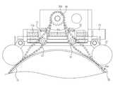
도 1은 본 발명의 실시예에 따른 파이프 자동용접장치를 나타낸 사시도이다.
도 2는 본 발명의 실시예에 따른 용접장치의 단면도이다.
도 3은 본 발명의 실시예에 따른 전극봉의 동작 상태도이다.
도 4는 본 발명의 실시예에 따른 파이프 자동용접장치의 내부를 나타낸 사시도이다.
도 5는 본 발명의 실시예에 따른 체인의 연결구조를 나타낸 것이다.
도 6은 본 발명의 실시예에 따른 아이들 스프라켓을 이동시키는 이송유닛을 나타낸 것이다.
도 7은 본 발명의 실시예에 따른 자동용접장치의 체인 조임부가 동작되는 상태를 나타낸 동작 상태도이다.1 is a perspective view showing a pipe automatic welding apparatus according to an embodiment of the present invention.
2 is a cross-sectional view of a welding apparatus according to an embodiment of the present invention.
3 is an operation state diagram of an electrode according to an embodiment of the present invention.
Figure 4 is a perspective view showing the inside of the automatic pipe welding apparatus according to an embodiment of the present invention.
Figure 5 shows the connection structure of the chain according to an embodiment of the present invention.
Figure 6 shows a transfer unit for moving the idle sprocket in accordance with an embodiment of the present invention.
7 is an operation state diagram showing a state in which the chain tightening unit of the automatic welding device according to an embodiment of the present invention.
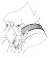
이하에서는 본 발명의 실시 예를 첨부 도면을 참조하여 상세히 설명 한다. 도 1은 본 발명의 실시예에 따른 파이프 자동용접장치를 나타낸 사시도이다.Hereinafter, embodiments of the present invention will be described in detail with reference to the accompanying drawings. 1 is a perspective view showing a pipe automatic welding apparatus according to an embodiment of the present invention.
도 1을 참조하면, 본실시 예에 따른 자동용접장치는 파이프(10)의 둘레를 따라 이동하는 로봇본체(20)와, 로봇본체(20)의 이동을 안내하는 체인(30)을 포함한다.Referring to FIG. 1, the automatic welding device according to the present embodiment includes a
로봇본체(20)는 용접을 위한 각종 장비가 설치되는 하우징(21)을 구비하고, 하우징(21)의 하측에는 체인(30)을 따라 이동시 파이프(10)의 외면과 접촉하여 구름 운동하는 휠(22)이 마련된다. 휠(22)의 외주면에는 파이프(10)의 외주면과 접촉하여 이동하는 경우 슬립을 방지하기 위한 마찰패드(미도시)가 마련될 수 있다.The robot
하우징(21)의 일측면에는 용접을 위한 와이어(wire)를 공급하는 와이어 피더부(23)가 설치되고, 하우징(21)의 타측에는 파이프(10)의 용접을 위한 용접토치(100)가 설치된다.와이어 피더부(23)에서 공급되는 와이어는 스풀(23a)을 통해 연속적으로 용접부에 공급된다.One side of the
용접토치(100)는 로봇본체(20)의 외면에 설치되어 용접을 위한 각종 장비가 내장되는 토치바디(110)를 구비하고, 토치바디(110)의 하측으로는 텅스텐 전극으로 이루어진 전극봉(120)의 끝 부분이 돌출된다.
이러한 용접토치(100)는 아르곤(Ar), 헬륨(He) 등과 같이 고온에서도 금속과 반응하지 않는 비활성 가스 분위기 속에서 전극봉(120)에 고주파 전류를 흘려주어 전극봉(120)과 모재 사이에 아크열을 발생시키고, 아크열에 의해 용가제(와이어)를 용착시켜 파이프의 용접부를 접합하는 TIG(Tungsten Inert Gas) 용접을 위한 장치이다.The
토치바디(110)는 일측이 가스공급관(미도시)과 연결되어 가스공급관에 의해 공급되는 비활성 가스를 공급받아 하측에 마련된 노즐부(130)를 통해 용접부에 토출한다.The
노즐부(130)는 폭이 좁은 용접부(협개선)에 진입이 용이하도록 폭이 좁은 슬림한 형태의 직육면체 형상으로 이루어질 수 있으며, 어느 양측면 사이의 폭이 협개선의 폭보다 좁도록 형성하여 좁은 용접부에 진입할 수 있는 형태라면 다양한 형상이 적용될 수 있음은 물론이다.The
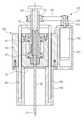
도 2는 본 실시예의 용접토치를 나타낸 단면도이다.2 is a sectional view showing a welding torch of the embodiment.
토치바디(110)의 내측에는 전극봉(120)을 고정하는 원통 형상의 회전바디(140)가 베어링(141)에 의해 그 외면이 지지되어 회전 가능하게 설치되고, 전극봉(120)은 회전바디(140) 내에 설치되는 전극봉 홀더(142)에 의해 고정된다.The inner side of the
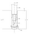
전극봉(120)은 회전바디(140)의 수직축(143)을 따라 배치되되 한쪽 끝 부분은 노즐부(130)의 외측으로 돌출되도록 마련된다.Electrode 120 is disposed along the
또한, 노즐부(130)의 외측으로 돌출된 전극봉(120)의 끝 부분(121)은 사선 형태로 가공된다. 이는 도 3에 도시한 바와 같이 전극봉(120)이 회전되면서 용접을 수행하는 경우 협개선 부분에서의 용접아크폭(125)을 증가시키기 위함이다.In addition, the
회전바디(140)는 회전바디 구동부(150)에 의해 동력을 제공받아 회전한다. 이러한 회전바디 구동부(150)는 토치바디(110)의 측면에 결합되는 절연재질의 모터 하우징(151)과, 모터 하우징(151) 내에 설치되는 구동모터(152)와, 구동모터(152)의 회전축(153)에 결합되는 구동풀리(154)와, 회전바디(140)에 결합되는 종동풀리(155)와, 구동모터(152)의 회전력을 회전바디(140)에 전달하도록 구동풀리(154)와 종동풀리(155)를 연결하는 벨트(156)를 포함한다.The rotating
구동모터(152)의 회전력은 벨트(156)를 통해 회전바디(140)에 전달되고, 회전바디(140)는 구동모터(152)의 회전력을 전달받아 수직축(143)을 중심으로 회전하게 된다.The rotational force of the
한편, 토치바디(110) 내부의 전극봉(120) 양측으로는 전극봉(120)에 의해 발생하는 고온의 열을 냉각하기 위한 냉각수가 이동하는 냉각수 공급관(160)이 배치된다.On the other hand, both sides of the
또한, 노즐부(130)의 상측에는 가스공급관으로부터 공급되는 실드가스가 노즐부(130)에 골고루 확산되어 공급되도록 금속으로 형성된 섬유 재질이 무수히 얽혀 하나의 판재를 이루는 메탈 파이버 시트(170)가 배치된다.In addition, a
이는 가스공급관을 통하여 토치바디(110) 내부에 공급된 실드가스는 메탈 파이버 시트(170)를 통하여 고르게 퍼져 확산된 후 노즐부(130)에 공급되게 함으로써 용접성을 향상시키기 위함이다.This is to improve weldability by allowing the shield gas supplied into the
즉, 실드가스는 메탈 파이버 시트(170)의 공극을 통하여 골고루 확산된 후 노즐부(130)에 공급됨에 따라 노즐부(130)로 공급되는 실드가스가 어느 한 쪽으로 편향되어 공급됨에 따른 용접성 저하를 방지할 수 있게 된다.That is, the shield gas is uniformly diffused through the pores of the
이러한 구성을 통하여 도 3에 도시한 바와 같이 폭이 좁은 협개선에 대한 파이프(10)의 용접시 본 실시예의 노즐부(130)는 협개선 내로 진입될 수 있게 되므로 노즐부(130)에 의해 분출되는 실드가스에 의한 용접부의 공기 유입의 차단성은 향상될 뿐만 아니라 사선 형태의 단면을 갖는 전극봉(120)의 끝 부분(121)에 의하여 전극봉(120)이 회전하는 경우 용접아크폭(125)을 확대시킬 수 있게 되므로 별도의 위빙이 필요치 않게 된다.Through this configuration, as shown in FIG. 3, when the
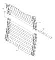
도 4는 본 발명의 실시예에 따른 로봇본체 내부를 나타낸 사시도이고, 도 5는 본 발명의 실시예에 따른 체인 구조를 나타낸 것이고, 도 6은 본 발명의 실시예에 따른 아이들 스프라켓을 이동시키는 이송유닛을 나타낸 것이다.Figure 4 is a perspective view showing the inside of the robot body according to an embodiment of the present invention, Figure 5 shows a chain structure according to an embodiment of the present invention, Figure 6 is a transfer to move the idle sprocket according to an embodiment of the present invention Represents a unit.
도 4내지 도 6을 참조하면, 로봇본체(20)는 파이프(20)의 외주면에 감겨 있는 체인(30)을 따라 이동하도록 마련된다. 이를 위해, 로봇본체(20)의 하우징(21) 상측에는 구동원(40)에 의해 회전하는 구동 스프라켓(50)을 구비하고, 구동 스프라켓(50)은 하우징(21)의 폭 방향을 가로지르도록 설치되는 구동축(52)의 양측에 각각 배치된다.4 to 6, the
구동축(52)은 일단이 구동원(40)에 연결되고, 타단은 베어링(미도시)에 의해 회전 가능하게 지지된 상태에 있게 된다.One end of the
구동원(40)은 하우징(21)에 설치되는 구동모터(41)와, 구동모터(41)의 축에 결합되는 구동풀리(42)와, 구동축(52)에 연결된 종동풀리(43)와, 구동풀리(42)의 회전력을 종동풀리(43)에 전달하는 벨트(44)를 포함한다.The drive source 40 includes a
체인(30)은 도 5에 도시한 바와 같이 다수의 체인링크(31)를 링크 연결핀(32)으로 연결하여 구동 스프라켓(50)의 톱니부(51)와 체결되는 홈을 갖는 중공형 체인으로 구성된다.
체인(30)의 길이는 파이프(10)의 둘레와 구동 스프라켓(50)의 둘레를 무리 없이 감아 돌릴 수 있을 정도로 설정된다. 이러한 체인(30)은 일단부가 분리된 상태에서 파이프(10)의 둘레와 구동 스프라켓(50)의 둘레를 감싸도록 배치된 후 링크 연결핀(32)을 체결함으로써 폐루프(closed loop)의 형태로 마련된다.The length of the
즉, 체인(30)은 도 4에 도시한 바와 같이 파이프(10)의 외면과 접촉하는 제1부분(30a)과, 구동 스프라켓(50)의 톱니부(51)와 체결되어 접촉하는 제2부분(30b)과, 제1부분(30a)과 제2부분(30b) 사이에 위치되는 제3부분(30c)으로 구성된 폐루프로 이루어지게 된다.That is, the
또,로봇본체(20)의 하우징(21) 내에는 파이프(10)와 구동 스프라켓(50)을 감싸는 체인(30)에 소정의 장력을 제공하기 위한 체인 조임부(60)가 마련된다.In addition, in the
체인 조임부(60)는 체인(30)의 서로 마주보는 제3부분(30c) 사이의 거리를 좁힘에 따라 체인(30)을 파이프(10)와 구동 스프라켓(50)을 조이는 방향으로 당겨 체인(30)에 조임력을 제공하도록 마련될 수 있다.The
이러한 체인 조임부(60)는 체인(30)의 제3부분(30c) 외측에 각각 배치되는 한 쌍의 아이들 스프라켓(61)과, 한 쌍의 아이들 스프라켓(61)을 전후 방향으로 직선 왕복 이동 시키기 위한 이송유닛(70)을 포함한다.The
이송유닛(70)은 한 쌍의 아이들 스프라켓(61)이 서로 멀어지거나 가까워지는 방향으로 이동시키기 위한 것으로서, 하우징(21)의 전후방향을 가로지르도록 배치되어 회전 가능하게 설치되는 스크류 축(71)과, 스크류 축(71)의 양측에 결합되는 한 쌍의 이동블록(72)과, 한 쌍의 이동블록(72)의 이동을 가이드 하기 위한 가이드부(80)를 포함한다.The
한 쌍의 아이들 스프라켓(61)은 이송유닛(70)에 의해 하우징(21)의 전후 방향으로 직선 왕복이동을 하게 되고, 서로 가까워지는 방향으로 이동하는 경우 대응하는 체인(30)의 제3부분(30c)과 치합되는 톱니부(61a)를 구비한다.The pair of
스크류 축(71)은 중앙부분을 기준으로 양측에 서로 반대되는 방향으로 형성된 나사산(71a,71b)을 구비하고, 한 쌍의 이동블록(72)은 대응하는 나사산(71a,71b)과 치합되는 스크류 너트(미도시)가 마련된다.The
즉, 나사산(71a,71b)은 일측이 시계 방향으로 감겨지는 나사산으로 이루어진 경우 타측은 반시계 방향으로 감겨지는 나사산으로 형성된다.That is, when the
스크류 축(71)의 일단부는 정,역회전 가능한 모터 등으로 이루어진 스크류 구동부(73)와 연결되어 동력을 전달받아 회전되고, 타단부는 베어링에 의하여 회전 가능하게 지지된다.One end of the
스크류 구동부(73)에 의해 스크류 축(71)이 일방향으로 회전시에는 한 쌍의 이동블록(72)은 서로 스크류 축(71)을 따라 서로 가까워지는 방향으로 이동하고, 일방향과 반대되는 타방향으로 회전시에는 한 쌍의 이동블록(72)은 스크류 축(71)을 따라 서로 멀어지는 방향으로 이동된다.When the
한편, 도시하지는 않았으나 한 쌍의 이동블록(72)이 서로 가까워지는 방향으로 이동하는 경우 체인(30)의 조임력을 조절하기 위해 스크류 구동부(73)에는 토크 리미터와 같은 센서가 구비될 수 있다.On the other hand, although not shown, when the pair of moving
가이드부(80)는 한 쌍의 이동블록(72)이 스크류 축(71)을 따라 이동될 때 회전되지 않고 안정적 선형 이동이 가능하도록 안내하는 기능을 수행한다.The
이러한 가이드부(80)는 로봇본체(20)의 하우징(21) 측면에 결합되는 가이드레일(81)과, 가이드레일(81)에 슬라이딩 가능하게 결합되는 슬라이더(82)를 포함한다.The
슬라이더(82)는 연결축(83)을 통하여 이동블록(72)과 고정되고, 연결축(83)에는 아이들 스프라켓(61)이 연결축(83)을 중심으로 회전 가능하게 설치된다.The
이하에서는 본 발명의 실시예에 따른 파이프용 자동용접장치의 작동에 대하여 설명한다. 도 7은 본 발명의 실시예에 따른 자동용접장치의 체인 조임부가 동작되는 상태를 나타낸 동작 상태도이다.Hereinafter will be described the operation of the automatic welding device for pipes according to an embodiment of the present invention. 7 is an operation state diagram showing a state in which the chain tightening unit of the automatic welding device according to an embodiment of the present invention.
먼저, 파이프용 자동용접장치를 용접하고자 하는 피대상물에 설치하는 경우 도 4 및 도 5에 도시한 바와 같이 분리 가능하게 마련된 체인(30)을 파이프(10)의 외주면과 구동 스프라켓(50)의 둘레를 감싸도록 배치하고, 분리된 체인(30)의 체인링크(31) 부분을 링크 연결핀(32)을 통해 연결시킨다.First, when the automatic welding device for pipes is installed on the object to be welded, the outer peripheral surface of the
이에 따라 파이프(10)와 구동 스프라켓(50)의 둘레를 감싸도록 배치되는 체인(30)은 상측이 구동 스프라켓(50)의 톱니부(51)와 체결된 상태로 걸려 지지된 폐루프의 형태로 마련된다.Accordingly, the
그리고, 체인 조임부(60)를 동작시키면 도 7에 도시한 바와 같이 체인(30)의 제3부분(30c) 외측에 배치되는 한 쌍의 아이들 스프라켓(61)이 서로 가까워지는 방향으로 이동하여 체인(30)의 제3부분(30c) 사이의 거리를 좁히도록 이동된다.When the
이에 따라, 파이프(10)와 접촉하는 체인(30)의 제1부분(30a)과 구동 스프라켓(50)과 접촉하는 체인(30)의 제2부분(30b)은 소정의 장력을 가진 상태로 대응하는 그 외면을 조이게 됨과 아울러 로봇본체(20)는 파이프(10)의 외면에 밀착되어 가압된 상태에 있게 된다.Accordingly, the
그리고, 구동 스프라켓(50)을 회전시키면 구동 스프라켓(50)은 체인(30)을 순차적으로 감음에 따라 로봇본체(20)를 이동시키고, 로봇본체(20)는 파이프(10)의 원주방향을 따라 감겨진 체인(30)을 따라 주행하면서 용접작업을 수행하게 된다.When the driving
따라서, 본 발명의 실시예의 자동용접장치는 파이프(10) 외면에 설치되는 가이드링 대신에 체인(30)을 이용하여 파이프(10)에 거치되고, 이를 이용하여 구동함에 따라 파이프(10)의 직경별로 별도의 가이드링을 구비할 필요가 없게 된다. 즉, 하나의 체인(30)을 길이 조절을 통하여 사용할 수 있게 되므로 공용성이 향상되게 된다.Therefore, the automatic welding device of the embodiment of the present invention is mounted on the
이상에서는 특정의 실시 예에 대하여 도시하고 설명하였다. 그러나 상기한 실시 예에만 한정되지 않으며 발명이 속하는 기술분야에서 통상의 지식을 가진 자라면 이하의 청구범위에 기재된 발명의 기술적 사상의 요지를 벗어남이 없이 얼마든지 다양하게 변경 실시할 수 있을 것이다.The foregoing has shown and described specific embodiments. It will be apparent to those skilled in the art that various modifications and variations can be made in the present invention without departing from the spirit and scope of the invention as defined in the appended claims.
10: 파이프,20: 로봇본체,
30: 체인,30a: 제1부분,
30b: 제2부분,30c: 제3부분,
40: 구동원,50: 구동 스프라켓,
60: 체인조임부,61: 아이들 스프라켓,
70: 이송유닛,71: 스크류 축,
72: 이동블록,80: 가이드부,
100: 용접토치,110: 토치바디,
120: 전극봉,130: 노즐부,
140: 회전바디,150: 회전바디 구동부,
160: 냉각수 공급관,170: 메탈 파이버 시트.10: pipe, 20: robot body,
30: chain, 30a: first part,
30b: second part, 30c: third part,
40: drive source, 50: drive sprocket,
60: chain fastener, 61: idle sprocket,
70: transfer unit, 71: screw shaft,
72: moving block, 80: guide part,
100: welding torch, 110: torch body,
120: electrode rod, 130: nozzle portion,
140: rotation body, 150: rotation body drive,
160: cooling water supply pipe, 170: metal fiber sheet.
Claims (11)
Translated fromKorean상기 로봇본체에 설치되는 용접토치;를 포함하고,
상기 용접토치는,
상기 로봇본체에 설치되는 토치바디;
상기 토치바디 내에서 수직축을 중심으로 회전 가능하게 설치되는 회전바디;
상기 회전바디를 회전시키기 위한 회전바디 구동부;
상기 토치바디에 마련되며 협개선(narrow gap) 용접부의 폭보다 얇은 폭을 가지는 형태로 상기 전극봉을 감싸는 노즐부;
상기 노즐부로 공급되는 실드가스의 확산을 위해 상기 노즐부 상측에 마련된 메탈 파이버 시트; 및
사선형태의 끝단을 가지며 상기 회전바디의 회전에 따라 회전되도록 상기 회전바디에 고정되는 전극봉;을 포함하는
파이프용 자동용접장치.Robot body moving along the circumference of the pipe;
It includes; welding torch installed in the robot body;
The welding torch,
A torch body installed in the robot body;
A rotating body rotatably installed about the vertical axis in the torch body;
A rotating body driver for rotating the rotating body;
A nozzle unit provided on the torch body and surrounding the electrode bar in a shape having a width smaller than the width of a narrow gap weld;
A metal fiber sheet provided above the nozzle unit for diffusion of the shield gas supplied to the nozzle unit; And
And having an oblique end and fixed to the rotating body to be rotated according to the rotation of the rotating body.
Automatic welding device for pipes.
상기 회전바디 구동부는,
상기 토치바디에 결합된 절연재질의 모터 하우징과,
상기 모터 하우징 내에 설치된 구동모터와,
상기 구동모터의 축에 결합된 구동풀리와,
상기 회전바디에 결합된 종동풀리와,
상기 구동풀리의 회전력을 상기 종동풀리에 전달하는 벨트를 포함하는
파이프용 자동용접장치.The method of claim 1,
The rotating body drive unit,
The motor housing of the insulating material coupled to the torch body,
A drive motor installed in the motor housing;
A drive pulley coupled to the shaft of the drive motor,
A driven pulley coupled to the rotating body,
A belt for transmitting the rotational force of the drive pulley to the driven pulley
Automatic welding device for pipes.
상기 토치바디 내에는 상기 전극봉 양측으로 나란히 배치되어 상기 전극봉과 상기 토치바디를 냉각하기 위한 냉각수공급관이 마련되는
파이프용 자동용접장치.The method of claim 1,
The torch body is arranged side by side on both sides of the electrode rod is provided with a cooling water supply pipe for cooling the electrode and the torch body
Automatic welding device for pipes.
상기 회전바디 외면을 지지하도록 상기 토치바디 내에 설치되는 베어링과,
상기 용접토치의 냉각을 위해 상기 토치바디 내에 설치되는 냉각수공급관을 더 포함하는
파이프용 자동용접장치.The method of claim 1,
A bearing installed in the torch body to support the outer surface of the rotating body;
Further comprising a cooling water supply pipe installed in the torch body for cooling the welding torch
Automatic welding device for pipes.
일측이 구동원에 의해 회전하도록 상기 로봇본체 내에 배치되는 구동 스프라켓과 치합되고, 타측이 상기 파이프 외면과 접촉하도록 배치되는 폐루프의 체인을 더 포함하며,
상기 로봇본체는 상기 구동 스프라켓이 상기 체인을 순차적으로 감음에 따라 상기 파이프 둘레를 이동하도록 마련되고,
상기 로봇본체 내에 설치되어 상기 체인에 조임력을 제공하는 체인 조임부를 더 포함하는
파이프용 자동용접장치.The method according to any one of claims 1, 3 to 4, 6,
It further includes a chain of the closed loop is engaged with the drive sprocket disposed in the robot body so that one side is rotated by the drive source, the other side is in contact with the outer surface of the pipe,
The robot body is provided to move around the pipe as the drive sprocket sequentially winds the chain,
It is further provided with a chain tightening unit installed in the robot body to provide a tightening force to the chain.
Automatic welding device for pipes.
상기 체인은,
상기 파이프 외면과 접촉하는 제1부분과,
상기 구동스프라켓과 접촉하는 제2부분과, 상기 제1부분과 상기 제2부분 사이에 위치하는 제3부분을 포함하고,
상기 체인 조임부는,
상기 제3부분 사이 거리를 가변시켜 상기 체인에 조임력을 제공하는
파이프용 자동용접장치.8. The method of claim 7,
The chain comprises:
A first portion in contact with the pipe outer surface,
A second portion in contact with the drive sprocket, and a third portion located between the first portion and the second portion,
The chain tightening unit,
Providing a tightening force to the chain by varying the distance between the third portions
Automatic welding device for pipes.
상기 체인 조임부는,
상기 제3부분 외측에 서로 마주보도록 배치되는 한 쌍의 아이들 스프라켓과,
상기 한 쌍의 아이들 스프라켓이 서로 멀어지거나 가까워지는 방향으로 직선 왕복 이동시키기 위한 이송유닛을 포함하는
파이프용 자동용접장치.The method of claim 8,
The chain tightening unit,
A pair of idle sprockets disposed to face each other outside the third portion,
And a transfer unit for linearly reciprocating the pair of idle sprockets in a direction away from or near each other.
Automatic welding device for pipes.
상기 이송유닛은,
상기 로봇본체에 회전 가능하게 설치되며 양측에 서로 반대되는 나사산을 갖는 스크류 축과,
상기 스크류 축의 양측에 치합되며 상기 한 쌍의 아이들 스프라켓이 각각 연결된 한 쌍의 이동블록과,
상기 한 쌍의 이동블록이 이동될 때 회전되지 않도록 상기 이동블록의 이동을 가이드하는 가이드부를 포함하는
파이프용 자동용접장치.The method of claim 9,
The transfer unit
A screw shaft rotatably installed on the robot body and having screw threads opposite to each other;
A pair of moving blocks meshed with both sides of the screw shaft and connected with the pair of idle sprockets,
It includes a guide for guiding the movement of the moving block so as not to rotate when the pair of moving blocks are moved.
Automatic welding device for pipes.
상기 가이드부는,
상기 로봇본체에 결합된 가이드레일과,
상기 가이드레일에 슬라이딩 가능하게 결합되며 상기 한 쌍의 아이들 스프라켓과 각각 연결된 한 쌍의 슬라이더를 포함하는
파이프용 자동용접장치.The method of claim 10,
The guide portion
A guide rail coupled to the robot body,
A pair of sliders slidably coupled to the guide rails and connected to the pair of idle sprockets, respectively;
Automatic welding device for pipes.
Priority Applications (1)
| Application Number | Priority Date | Filing Date | Title |
|---|---|---|---|
| KR1020120023913AKR101347343B1 (en) | 2012-03-08 | 2012-03-08 | Automatic welding device for pipe |
Applications Claiming Priority (1)
| Application Number | Priority Date | Filing Date | Title |
|---|---|---|---|
| KR1020120023913AKR101347343B1 (en) | 2012-03-08 | 2012-03-08 | Automatic welding device for pipe |
Publications (2)
| Publication Number | Publication Date |
|---|---|
| KR20130102796A KR20130102796A (en) | 2013-09-23 |
| KR101347343B1true KR101347343B1 (en) | 2014-01-10 |
Family
ID=49452334
Family Applications (1)
| Application Number | Title | Priority Date | Filing Date |
|---|---|---|---|
| KR1020120023913AActiveKR101347343B1 (en) | 2012-03-08 | 2012-03-08 | Automatic welding device for pipe |
Country Status (1)
| Country | Link |
|---|---|
| KR (1) | KR101347343B1 (en) |
Cited By (1)
| Publication number | Priority date | Publication date | Assignee | Title |
|---|---|---|---|---|
| CN109352104A (en)* | 2018-12-12 | 2019-02-19 | 中国石油大学(华东) | A kind of electric spark cutting sampler for small samples of the outer wall of in-service oil and gas pipelines |
Families Citing this family (13)
| Publication number | Priority date | Publication date | Assignee | Title |
|---|---|---|---|---|
| CN103658942B (en)* | 2013-12-31 | 2015-09-16 | 哈尔滨工业大学 | swing arc narrow gap MIG/MAG welding torch |
| KR20150144410A (en) | 2014-06-16 | 2015-12-28 | 현대중공업 주식회사 | TIG Welding Apparatus |
| CN105033413A (en)* | 2015-06-29 | 2015-11-11 | 张洪涛 | Tungsten electrode autorotation type non-melt electrode argon arc welding device |
| CN104985310B (en)* | 2015-07-07 | 2017-06-06 | 扬州鑫凯诚机器人系统有限公司 | Welding workstation welding chuck |
| CN106271247B (en)* | 2016-08-26 | 2018-06-12 | 唐山松一科技有限公司 | Multi-function robot welds switch board |
| CN106271248B (en)* | 2016-08-26 | 2018-09-07 | 江西鼎好科技发展有限公司 | Firm humanoid robot welds switch board |
| CN106624284B (en)* | 2016-12-28 | 2019-05-07 | 山东大学 | A complete set of welding equipment and working method for automatic vertical welding of 9% Ni steel in LNG storage tanks |
| DE102017122069A1 (en)* | 2017-09-22 | 2019-03-28 | Illinois Tool Works Inc. | Orbital welding device with improved safety and reduced failure probability |
| CN108526804B (en)* | 2018-05-22 | 2024-04-05 | 无锡锡能锅炉有限公司 | Assembling tool for spiral tube set header |
| WO2022139434A1 (en)* | 2020-12-22 | 2022-06-30 | 주식회사 웰드텍 | Automatic welding system for pipe |
| CN113828977A (en)* | 2021-08-25 | 2021-12-24 | 山东水总有限公司 | Welding device and welding process for large-diameter steel pipe for hydraulic engineering |
| CN115452949A (en)* | 2022-10-19 | 2022-12-09 | 内蒙古电力(集团)有限责任公司内蒙古电力科学研究院分公司 | Magnetostrictive ultrasonic guided wave flaw detection equipment for pipelines |
| CN116175014B (en)* | 2022-12-29 | 2024-02-09 | 苏州威奥得焊材科技有限公司 | Pipeline welding device |
Citations (2)
| Publication number | Priority date | Publication date | Assignee | Title |
|---|---|---|---|---|
| JPH09327772A (en)* | 1996-06-10 | 1997-12-22 | Kawasaki Heavy Ind Ltd | Rotary arc welding torch |
| KR200176128Y1 (en)* | 1999-10-18 | 2000-03-15 | 주식회사오주산업 | Welding machine using synthetic regin for the use of joiut welding of buried piping |
- 2012
- 2012-03-08KRKR1020120023913Apatent/KR101347343B1/enactiveActive
Patent Citations (2)
| Publication number | Priority date | Publication date | Assignee | Title |
|---|---|---|---|---|
| JPH09327772A (en)* | 1996-06-10 | 1997-12-22 | Kawasaki Heavy Ind Ltd | Rotary arc welding torch |
| KR200176128Y1 (en)* | 1999-10-18 | 2000-03-15 | 주식회사오주산업 | Welding machine using synthetic regin for the use of joiut welding of buried piping |
Cited By (1)
| Publication number | Priority date | Publication date | Assignee | Title |
|---|---|---|---|---|
| CN109352104A (en)* | 2018-12-12 | 2019-02-19 | 中国石油大学(华东) | A kind of electric spark cutting sampler for small samples of the outer wall of in-service oil and gas pipelines |
Also Published As
| Publication number | Publication date |
|---|---|
| KR20130102796A (en) | 2013-09-23 |
Similar Documents
| Publication | Publication Date | Title |
|---|---|---|
| KR101347343B1 (en) | Automatic welding device for pipe | |
| KR101508813B1 (en) | Automatic pipe machining carriage | |
| US8278599B2 (en) | Belt drive for feeding welding wire | |
| US3604612A (en) | Orbital track-traveling carriage mechanism for performing welding and other physical operations | |
| KR101037773B1 (en) | Orbital Pipe Automatic Welding Device | |
| KR20130139613A (en) | Grinding device for pipe welding part | |
| KR101422729B1 (en) | Carriage for processing pipe | |
| US3840170A (en) | Automatic, circumferentially traveling mechanism for use in automatic circumferential welding or cutting device | |
| KR20120139498A (en) | Detachable rail type text welding machiene | |
| KR20090084453A (en) | Pipe inner welding device | |
| KR101397186B1 (en) | Weaving type welding apparatus for welding pipe | |
| CN115338579A (en) | Pipeline welding process and pipeline welding robot for staggered edge welding of pipeline welded junction | |
| KR101313556B1 (en) | Automatic welding device for pipe | |
| KR20160000707A (en) | Internal shaping roundness apparatus and pipe line connecting method in construction site using the same | |
| CN208195900U (en) | A kind of welding tractor of anti-arc light and welding slag splashing | |
| US4092928A (en) | Traveling support apparatus | |
| KR101505733B1 (en) | Automatic Welding Apparatus for pipe | |
| KR20100025368A (en) | Automatic welding device for cylindrical outer surface welding | |
| JP2011011248A (en) | Method and device for circumferential weld of fixed tube | |
| KR101091994B1 (en) | Strip welder with long body | |
| KR20240120885A (en) | Apparatus of welding | |
| JPH02179359A (en) | Automatic tig welding equipment for piping | |
| CN115958272A (en) | Argon arc welding gun for thin-wall stainless steel water pipe | |
| KR100639608B1 (en) | Automatic bending machine for deformation correction of steel plate | |
| KR200450577Y1 (en) | Submerged Arc Welding Equipment for Small Diameter Products |
Legal Events
| Date | Code | Title | Description |
|---|---|---|---|
| A201 | Request for examination | ||
| PA0109 | Patent application | Patent event code:PA01091R01D Comment text:Patent Application Patent event date:20120308 | |
| PA0201 | Request for examination | ||
| E902 | Notification of reason for refusal | ||
| PE0902 | Notice of grounds for rejection | Comment text:Notification of reason for refusal Patent event date:20130513 Patent event code:PE09021S01D | |
| PG1501 | Laying open of application | ||
| E701 | Decision to grant or registration of patent right | ||
| PE0701 | Decision of registration | Patent event code:PE07011S01D Comment text:Decision to Grant Registration Patent event date:20131001 | |
| GRNT | Written decision to grant | ||
| PR0701 | Registration of establishment | Comment text:Registration of Establishment Patent event date:20131226 Patent event code:PR07011E01D | |
| PR1002 | Payment of registration fee | Payment date:20131227 End annual number:3 Start annual number:1 | |
| PG1601 | Publication of registration | ||
| PR1001 | Payment of annual fee | Payment date:20201201 Start annual number:8 End annual number:8 | |
| PR1001 | Payment of annual fee | Payment date:20211201 Start annual number:9 End annual number:9 | |
| PR1001 | Payment of annual fee | Payment date:20221201 Start annual number:10 End annual number:10 | |
| PR1001 | Payment of annual fee | Payment date:20231129 Start annual number:11 End annual number:11 |