KR101346468B1 - Test chip with plug for measuring the concentration of an analyte in a liquid, housing for test chip and socket for plug - Google Patents
Test chip with plug for measuring the concentration of an analyte in a liquid, housing for test chip and socket for plugDownload PDFInfo
- Publication number
- KR101346468B1 KR101346468B1KR1020097023090AKR20097023090AKR101346468B1KR 101346468 B1KR101346468 B1KR 101346468B1KR 1020097023090 AKR1020097023090 AKR 1020097023090AKR 20097023090 AKR20097023090 AKR 20097023090AKR 101346468 B1KR101346468 B1KR 101346468B1
- Authority
- KR
- South Korea
- Prior art keywords
- measuring
- measurement
- delete delete
- sample handling
- sample
- Prior art date
- Legal status (The legal status is an assumption and is not a legal conclusion. Google has not performed a legal analysis and makes no representation as to the accuracy of the status listed.)
- Expired - Fee Related
Links
Images


Classifications
- G—PHYSICS
- G01—MEASURING; TESTING
- G01N—INVESTIGATING OR ANALYSING MATERIALS BY DETERMINING THEIR CHEMICAL OR PHYSICAL PROPERTIES
- G01N27/00—Investigating or analysing materials by the use of electric, electrochemical, or magnetic means
- G01N27/26—Investigating or analysing materials by the use of electric, electrochemical, or magnetic means by investigating electrochemical variables; by using electrolysis or electrophoresis
- G01N27/416—Systems
- G01N27/447—Systems using electrophoresis
- G01N27/44704—Details; Accessories
- G01N27/44717—Arrangements for investigating the separated zones, e.g. localising zones
- G01N27/4473—Arrangements for investigating the separated zones, e.g. localising zones by electric means
- G—PHYSICS
- G01—MEASURING; TESTING
- G01N—INVESTIGATING OR ANALYSING MATERIALS BY DETERMINING THEIR CHEMICAL OR PHYSICAL PROPERTIES
- G01N33/00—Investigating or analysing materials by specific methods not covered by groups G01N1/00 - G01N31/00
- G01N33/48—Biological material, e.g. blood, urine; Haemocytometers
- G01N33/483—Physical analysis of biological material
- G01N33/487—Physical analysis of biological material of liquid biological material
- G01N33/49—Blood
- B—PERFORMING OPERATIONS; TRANSPORTING
- B01—PHYSICAL OR CHEMICAL PROCESSES OR APPARATUS IN GENERAL
- B01L—CHEMICAL OR PHYSICAL LABORATORY APPARATUS FOR GENERAL USE
- B01L3/00—Containers or dishes for laboratory use, e.g. laboratory glassware; Droppers
- B01L3/50—Containers for the purpose of retaining a material to be analysed, e.g. test tubes
- B01L3/502—Containers for the purpose of retaining a material to be analysed, e.g. test tubes with fluid transport, e.g. in multi-compartment structures
- B01L3/5027—Containers for the purpose of retaining a material to be analysed, e.g. test tubes with fluid transport, e.g. in multi-compartment structures by integrated microfluidic structures, i.e. dimensions of channels and chambers are such that surface tension forces are important, e.g. lab-on-a-chip
- B01L3/502715—Containers for the purpose of retaining a material to be analysed, e.g. test tubes with fluid transport, e.g. in multi-compartment structures by integrated microfluidic structures, i.e. dimensions of channels and chambers are such that surface tension forces are important, e.g. lab-on-a-chip characterised by interfacing components, e.g. fluidic, electrical, optical or mechanical interfaces
- G—PHYSICS
- G01—MEASURING; TESTING
- G01N—INVESTIGATING OR ANALYSING MATERIALS BY DETERMINING THEIR CHEMICAL OR PHYSICAL PROPERTIES
- G01N27/00—Investigating or analysing materials by the use of electric, electrochemical, or magnetic means
- G01N27/26—Investigating or analysing materials by the use of electric, electrochemical, or magnetic means by investigating electrochemical variables; by using electrolysis or electrophoresis
- G01N27/416—Systems
- G01N27/447—Systems using electrophoresis
- G01N27/44704—Details; Accessories
- G01N27/44743—Introducing samples
- B—PERFORMING OPERATIONS; TRANSPORTING
- B01—PHYSICAL OR CHEMICAL PROCESSES OR APPARATUS IN GENERAL
- B01L—CHEMICAL OR PHYSICAL LABORATORY APPARATUS FOR GENERAL USE
- B01L2200/00—Solutions for specific problems relating to chemical or physical laboratory apparatus
- B01L2200/02—Adapting objects or devices to another
- B01L2200/026—Fluid interfacing between devices or objects, e.g. connectors, inlet details
- B01L2200/027—Fluid interfacing between devices or objects, e.g. connectors, inlet details for microfluidic devices
- B—PERFORMING OPERATIONS; TRANSPORTING
- B01—PHYSICAL OR CHEMICAL PROCESSES OR APPARATUS IN GENERAL
- B01L—CHEMICAL OR PHYSICAL LABORATORY APPARATUS FOR GENERAL USE
- B01L2200/00—Solutions for specific problems relating to chemical or physical laboratory apparatus
- B01L2200/04—Exchange or ejection of cartridges, containers or reservoirs
- B—PERFORMING OPERATIONS; TRANSPORTING
- B01—PHYSICAL OR CHEMICAL PROCESSES OR APPARATUS IN GENERAL
- B01L—CHEMICAL OR PHYSICAL LABORATORY APPARATUS FOR GENERAL USE
- B01L2200/00—Solutions for specific problems relating to chemical or physical laboratory apparatus
- B01L2200/10—Integrating sample preparation and analysis in single entity, e.g. lab-on-a-chip concept
- B—PERFORMING OPERATIONS; TRANSPORTING
- B01—PHYSICAL OR CHEMICAL PROCESSES OR APPARATUS IN GENERAL
- B01L—CHEMICAL OR PHYSICAL LABORATORY APPARATUS FOR GENERAL USE
- B01L2300/00—Additional constructional details
- B01L2300/06—Auxiliary integrated devices, integrated components
- B01L2300/0627—Sensor or part of a sensor is integrated
- B01L2300/0645—Electrodes
- B—PERFORMING OPERATIONS; TRANSPORTING
- B01—PHYSICAL OR CHEMICAL PROCESSES OR APPARATUS IN GENERAL
- B01L—CHEMICAL OR PHYSICAL LABORATORY APPARATUS FOR GENERAL USE
- B01L2300/00—Additional constructional details
- B01L2300/08—Geometry, shape and general structure
- B01L2300/0861—Configuration of multiple channels and/or chambers in a single devices
- B—PERFORMING OPERATIONS; TRANSPORTING
- B01—PHYSICAL OR CHEMICAL PROCESSES OR APPARATUS IN GENERAL
- B01L—CHEMICAL OR PHYSICAL LABORATORY APPARATUS FOR GENERAL USE
- B01L2400/00—Moving or stopping fluids
- B01L2400/04—Moving fluids with specific forces or mechanical means
- B01L2400/0403—Moving fluids with specific forces or mechanical means specific forces
- B01L2400/0415—Moving fluids with specific forces or mechanical means specific forces electrical forces, e.g. electrokinetic
- B01L2400/0421—Moving fluids with specific forces or mechanical means specific forces electrical forces, e.g. electrokinetic electrophoretic flow
- B—PERFORMING OPERATIONS; TRANSPORTING
- B01—PHYSICAL OR CHEMICAL PROCESSES OR APPARATUS IN GENERAL
- B01L—CHEMICAL OR PHYSICAL LABORATORY APPARATUS FOR GENERAL USE
- B01L3/00—Containers or dishes for laboratory use, e.g. laboratory glassware; Droppers
- B01L3/50—Containers for the purpose of retaining a material to be analysed, e.g. test tubes
- B01L3/502—Containers for the purpose of retaining a material to be analysed, e.g. test tubes with fluid transport, e.g. in multi-compartment structures
- B01L3/5027—Containers for the purpose of retaining a material to be analysed, e.g. test tubes with fluid transport, e.g. in multi-compartment structures by integrated microfluidic structures, i.e. dimensions of channels and chambers are such that surface tension forces are important, e.g. lab-on-a-chip
- B01L3/50273—Containers for the purpose of retaining a material to be analysed, e.g. test tubes with fluid transport, e.g. in multi-compartment structures by integrated microfluidic structures, i.e. dimensions of channels and chambers are such that surface tension forces are important, e.g. lab-on-a-chip characterised by the means or forces applied to move the fluids
- B—PERFORMING OPERATIONS; TRANSPORTING
- B01—PHYSICAL OR CHEMICAL PROCESSES OR APPARATUS IN GENERAL
- B01L—CHEMICAL OR PHYSICAL LABORATORY APPARATUS FOR GENERAL USE
- B01L9/00—Supporting devices; Holding devices
- B01L9/52—Supports specially adapted for flat sample carriers, e.g. for plates, slides, chips
- B01L9/527—Supports specially adapted for flat sample carriers, e.g. for plates, slides, chips for microfluidic devices, e.g. used for lab-on-a-chip
- Y—GENERAL TAGGING OF NEW TECHNOLOGICAL DEVELOPMENTS; GENERAL TAGGING OF CROSS-SECTIONAL TECHNOLOGIES SPANNING OVER SEVERAL SECTIONS OF THE IPC; TECHNICAL SUBJECTS COVERED BY FORMER USPC CROSS-REFERENCE ART COLLECTIONS [XRACs] AND DIGESTS
- Y10—TECHNICAL SUBJECTS COVERED BY FORMER USPC
- Y10T—TECHNICAL SUBJECTS COVERED BY FORMER US CLASSIFICATION
- Y10T29/00—Metal working
- Y10T29/49—Method of mechanical manufacture
- Y10T29/49826—Assembling or joining
Landscapes
- Health & Medical Sciences (AREA)
- Life Sciences & Earth Sciences (AREA)
- Chemical & Material Sciences (AREA)
- Molecular Biology (AREA)
- General Health & Medical Sciences (AREA)
- Analytical Chemistry (AREA)
- Chemical Kinetics & Catalysis (AREA)
- Physics & Mathematics (AREA)
- Pathology (AREA)
- General Physics & Mathematics (AREA)
- Immunology (AREA)
- Biochemistry (AREA)
- Electrochemistry (AREA)
- Hematology (AREA)
- Engineering & Computer Science (AREA)
- Biomedical Technology (AREA)
- Dispersion Chemistry (AREA)
- Clinical Laboratory Science (AREA)
- Ecology (AREA)
- Food Science & Technology (AREA)
- Medicinal Chemistry (AREA)
- Urology & Nephrology (AREA)
- Biophysics (AREA)
- Investigating Or Analyzing Materials By The Use Of Electric Means (AREA)
- Automatic Analysis And Handling Materials Therefor (AREA)
- Investigating Or Analysing Biological Materials (AREA)
Abstract
Translated fromKoreanDescription
Translated fromKorean본 발명은 액체 샘플 중의 성분에 대한 센서에 관한 것이다. 특히, 본 발명은 환자와 같은 사용자에 의해 쉽게 취급될 수 있는 혈액과 같은 샘플 중에서 하전된 종(species) 농도, 특히 이온 농도, 예컨대 리튬 이온 농도를 평가하기 위한 센서에 관한 것이다.The present invention relates to sensors for components in a liquid sample. In particular, the present invention relates to a sensor for evaluating charged species concentrations, especially ion concentrations, such as lithium ion concentrations, in a sample such as blood that can be easily handled by a user such as a patient.
무기 이온은 생명에 필수 요건이며 또 음용수, 혈액 및 생물의 세포뿐만 아니라 환경에서 다량으로 발견되고 있다. 세포 내부 및 외부에서 다수 이온, 예컨대 나트륨, 칼륨, 마그네슘, 및 칼슘의 존재는 살아있는 생물에 필수적이다. 따라서, 동물 및 인간의 혈액 및 혈액 세포 중의 이온 농도의 측정은 다수의 체내 작용에 아주 중요하다.Inorganic ions are essential for life and are found in large quantities in drinking water, blood and living cells as well as in the environment. The presence of many ions, such as sodium, potassium, magnesium, and calcium, both inside and outside the cell, is essential for living organisms. Therefore, measurement of the ionic concentration in blood and blood cells of animals and humans is very important for a large number of body functions.
통상 리튬은 혈장에서 전혀 존재하지 않거나 미량 원소로서 존재하지만, 양극성 기분 장애를 치료하기 위한 약물로서 사용된다. 전세계적으로 백만명 이상의 사람들이 매일 리튬을 섭취하고 있는 것으로 추산된다. 리튬 사용에서의 결점은 아 주 낮은 치료 지수, 즉 독성 농도와 치료 농도 사이의 비율이 낮은 것이다. 대부분의 환자들은 0.4-1.2 밀리몰/L 리튬의 혈장 농도에는 잘 반응하는 반면에, 1.6 밀리몰/L 이상의 리튬 농도는 독성으로 간주할 것이다. 장시간의 높은 혈액 리튬 수준은 신경계에 영구적인 손상을 초래할 수 있고 치명적일 수 있다. 따라서 치료하는 동안 리튬 농도의 모니터링이 필수적이며, 리튬 수준을 소망하는 수준으로 유지하기 위해 2개월 마다 주기적으로 확인한다.Usually lithium is not present in plasma or exists as a trace element, but is used as a drug to treat bipolar mood disorder. More than one million people worldwide are estimated to be consuming lithium daily. The drawback with lithium use is a very low therapeutic index, i.e. the ratio between the toxic and therapeutic concentrations is low. Most patients will respond well to plasma concentrations of 0.4-1.2 mmol / L lithium, whereas lithium concentrations above 1.6 mmol / L will be considered toxic. Prolonged high blood lithium levels can cause permanent damage to the nervous system and can be fatal. Therefore, monitoring of lithium concentration during treatment is essential and is checked periodically every two months to maintain the lithium level at the desired level.
전체 혈액 중의 리튬의 직접적인 측정 및 혈장 중의 무기 양이온의 측정은 E. Vrouwe 등에 의해Electrophoresis 2004, 25, 1660-1667 및Electrophoresis 2005, 26, 3032-3042에 기재되고 예시된 바 있다. 소정의 샘플 로딩(loading) 및 칼럼 커플링 원리를 적용하는 것에 의한 마이크로칩 모세관 전기영동 (CE)을 이용함으로써, 혈액 중의 알칼리 금속의 농도를 1 방울의 전체 혈액에서 측정하였다. 핑거 스틱(finger stick)으로부터 수집한 혈액은 혈액으로부터 성분을 추출하거나 제거하지 않고 칩(chip) 상으로 전달하였다. 리튬 농도는 샘플 예비처리없이 리튬 요법 상의 환자로부터 얻은 혈장에서 측정할 수 있다. 도전성 검출을 이용한 칩을 사용함으로써, 140 밀리몰/L 나트륨 매트릭스 중의 리튬에 대하여 0.1 밀리몰/L의 검출 한도를 얻었다.Direct measurement of lithium in whole blood and determination of inorganic cations in plasma are described and illustrated by E. Vrouwe et al. In
이들 기재에서, 혈액 샘플의 성분들은 전기영동적으로 마이크로채널(micro-channel) 내부에서 분리된다. 괌심있는 이온 성분을 선택하여 이들을 검출 전극으로 안내하기 위하여 이중 T 주입 기하(double T injection geometry)를 이용한다.In these descriptions, the components of the blood sample are electrophoretically separated within a micro-channel. Double T injection geometry is used to select the gentle ionic components and guide them to the sensing electrodes.
액체 샘플 중의 이온 농도를 측정하는 방법 및 장치는 동시계류중인 PCT 출원 PCT/EP2006/011148호에 기재되어 있으며, 그 내용은 본 명세서에 참고문헌으로 포함된다. 이 PCT 출원은 샘플 중의 하전된 종의 농도 측정을 위한 장치를 개시하며, 상기 샘플은 복수 유형의 하전된 종 및 적어도 1개의 불용성 성분을 포함하며, 상기 장치는 필터 작용을 하는 적어도 1개의 개구(opening)를 갖는 적어도 1개의 채널, 적어도 1개 채널을 따라 배열된 적어도 2개의 전기영동 전극, 및 적어도 1개 채널 중의 적어도 1개 유형의 하전된 종을 측정하기 위한 적어도 1개의 센서를 포함한다.A method and apparatus for measuring the ion concentration in a liquid sample are described in co-pending PCT application PCT / EP2006 / 011148, the contents of which are incorporated herein by reference. This PCT application discloses an apparatus for measuring the concentration of a charged species in a sample, the sample comprising a plurality of types of charged species and at least one insoluble component, the apparatus having at least one aperture opening, at least two electrophoretic electrodes arranged along at least one channel, and at least one sensor for measuring at least one type of charged species of at least one channel.
이러한 장치에 사용된 개구 및 채널의 치수는 보통 필요한 액체의 양 및 장치의 크기를 감소시키기 위하여 아주 작다. 전형적인 채널 치수는 폭 1 cm 미만 및 깊이 100 ㎛ 미만 정도이다. 따라서 상기 장치는 장치에 사용되는 원료의 양을 최소화하기 위하여도 아주 작을 수 있다. 원료는 흔히 유리처럼 고가이다.The dimensions of the openings and channels used in such devices are usually very small to reduce the amount of liquid required and the size of the device. Typical channel dimensions are less than 1 cm wide and less than 100 탆 deep. Thus, the apparatus can be very small in order to minimize the amount of raw material used in the apparatus. Raw materials are often as expensive as glass.
상기 장치는 또한 환자 또는 다른 사용자에 의해 용이하게 이용될 수 있어야 한다. 특히, 양극성 기분장애 또는 유사한 질병에 걸린 환자들은 손이 흔들리거나 떠는 증상이 있어 작은 물품을 취급하는데 어려움이 있었다.The device should also be readily usable by the patient or other user. In particular, patients suffering from bipolar mood disorder or similar illness have difficulty handling small articles because of hand shaking or swelling.
또한 혈액 샘플 및 따라서 채널은 혈액 또는 기타 액체에 의해 쉽게 오염될 수 있어 철저한 세척 및 멸균 없이는 재사용될 수 없다.Also the blood sample and thus the channel can be easily contaminated by blood or other liquids and can not be reused without thorough washing and sterilization.
대조적으로, 공지된 종래 기술의 측정 장치는 고가인 복잡한 미세유체성 및 전자 부품이므로 1회용으로는 적합하지 않다.In contrast, known prior art measuring devices are not suitable for single use because they are expensive microfluidic and electronic components that are expensive.
본 발명의 목적은 소형 샘플을 측정하기 위한 액체 샘플 측정 장치의 취급이 용이한 장치 및 방법을 제공하는 것이다.It is an object of the present invention to provide an apparatus and method for easy handling of a liquid sample measuring device for measuring small samples.
본 발명의 다른 목적은 1회용으로 사용될 수 있는 한편 개선된 측정 수법이 이용될 수 있는 측정 장치를 제공하는 것이다.Another object of the present invention is to provide a measuring device which can be used in a single use, while an improved measuring method can be used.
발명의 요약Summary of the Invention
본 발명의 이들 및 기타 목적은 본 발명에 따른 측정 샘플 취급 장치 및 액체 샘플을 취하는 방법에 의해 달성되며, 상기 측정 샘플 취급 장치는 측정 장치 및 취급 유닛(unit)을 포함한다.These and other objects of the present invention are achieved by a measuring sample handling device and a method of taking a liquid sample according to the invention, wherein the measuring sample handling device comprises a measuring device and a handling unit.
액체 샘플을 취하는 측정 장치는 다음을 포함한다: 액체 샘플과 접촉하여 사용하기 위한 측정 표면을 갖는 측정부(measurement portion), 및 복수의 전기적 접점을 갖는 플러그부, 이때 플러그부는 측정 평가 장치의 소켓에 장착된다. 측정 표면은 액체 샘플의 액체가 전기적 접점(electrical contacts)과 접촉하지 않도록 플러그부 보다는 측정장치의 상이한 위치에서 배열될 수 있다. 특히, 플러그부는 측정 표면 보다는 측정 장치의 상이한 측면에서 배열될 수 있다.A measurement device for taking a liquid sample includes: a measurement portion having a measurement surface for use in contact with a liquid sample; and a plug portion having a plurality of electrical contacts, wherein the plug portion is connected to a socket of the measurement evaluation device Respectively. The measuring surface may be arranged at different positions of the measuring device than the plug portion so that the liquid of the liquid sample does not come into contact with the electrical contacts. In particular, the plug portion can be arranged on different sides of the measuring device than on the measuring surface.
측정 표면 및 측정부는 동일한 원료, 예컨대 유리로부터 제조될 수 있고 또 일체화(one piece)될 수 있다. 상기 측정 장치는 또한 전기적 접점에 결합된 복수의 전극을 포함할 수 있다. 상기 측정 장치는 스위치, 트랜지스터와 같은 능동전기부품도 전원 공급기도 갖지 않을 수 있다. 일부 경우, 측정 장치는 온도 센서 등과 같은 일부 수동 전기부품을 포함할 수 있다.The measuring surface and measuring part can be made from the same raw material, for example glass, and can be one piece. The measuring device may also comprise a plurality of electrodes coupled to the electrical contacts. The measuring device may not have active electrical components such as switches, transistors, or power supplies. In some cases, the measuring device may include some passive electrical components such as temperature sensors and the like.
조립하는 동안, 측정 장치는 측정 표면에 대한 제1 개구 및 복수의 전기적 접점에 대한 적어도 1개의 제2 개구를 갖는 취급 유닛에 삽입될 수 있다. 따라서 취급 유닛에 삽입될 때, 측정 표면은 액체 샘플을 위치하기 위해 사용자 또는 환자가 접근가능하다. 반면에 플러그부는 예컨대 소켓에 의해 전기적 접점에 접근되게 하는 취급 유닛의 제2 개구를 통하여 접근할 수 있다. 따라서, 취급 유닛은 액체가 측정 장치의 플러그부에서 전기적 접점과 접촉하지 않도록 전기적 접점 시일(seal)을 형성할 수 있다.During assembly, the measuring device may be inserted into a handling unit having a first opening for the measuring surface and at least one second opening for the plurality of electrical contacts. Thus, when inserted into the handling unit, the measuring surface is accessible to the user or patient to position the liquid sample. While the plug portion can be accessed through a second opening of the handling unit which allows the electrical contact to be approached by the socket, for example. Thus, the handling unit can form an electrical contact seal so that the liquid does not come into contact with the electrical contacts at the plug portion of the measuring device.
상기 취급 유닛은 모든 전기적 접점이 측정장치에 의해 제공되므로 임의 전기 부품을 포함하지 않을 수 있다. 일부 경우에서, 상기 취급 유닛은 전기적 접점 및 전기 부품을 포함할 수 있다.The handling unit may not include any electrical components since all electrical contacts are provided by the measuring device. In some cases, the handling unit may include electrical contacts and electrical components.
상기 취급 유닛은 측정장치에 비하여 실질적으로 대형일 수 있다. 따라서, 상기 취급 유닛은 손을 떨거나 또는 유사한 증상이 있는 환자라도 측정 샘플 취급 장치의 용이하고 안전한 취급을 위해 손에 집기 쉬운 크기일 수 있다. 동시에 측정 장치는 안전한 측정에 필요한 액체 샘플의 양을 최소화하기 위하여 소형으로 유지될 수 있다. 또한 더 작은 측정 장치는 제조하는데 더 저렴할 수 있다. 측정 샘플 취급 장치는 수회 또는 1회 사용에 적합한 일회용 장치일 수 있다. 이것은 액체 샘플이 멸균 및/또는 청정 환경을 요하는 혈액 또는 다른 샘플과 같은 체액일 때 특히 유용하다.The handling unit may be substantially larger than the measuring device. Thus, the handling unit may be of a size that is easy to grasp for easy and safe handling of the measurement sample handling device, even if the hand is shaken or the patient has similar symptoms. At the same time, the measuring device can be kept small to minimize the amount of liquid sample required for safe measurement. Smaller measuring devices may also be cheaper to manufacture. The measuring sample handling device may be a disposable device suitable for multiple or single use. This is particularly useful when the liquid sample is a body fluid such as blood or other samples that requires sterilization and / or a clean environment.
상기 취급 유닛은 일렬 또는 평행하게 복수의 샘플 측정을 실시하기 위한 복수의 측정 장치를 수용하도록 변형(adapted)될 수 있다. 측정 장치는, 측정 샘플 취급 장치가 측정 평가장치의 소켓에 삽입될 때, 예컨대 복수의 전기 핀(electrical pin)에 의해 외부로부터 플러그부에 대한 용이한 접근을 제2 개구가 제공하도록, 취급 유닛의 특정 면에 위치할 수 있다. 복수의 전기 핀은 측정 장치 또는 측정 샘플 취급 장치가 소켓에 장착될 때, 측정 장치의 복수의 전기적 접점과 전기적으로 접촉하도록 배열될 수 있다.The handling unit may be adapted to accommodate a plurality of measurement devices for performing a plurality of sample measurements in a row or in parallel. The measuring device is arranged so that when the measuring sample handling device is inserted into the socket of the measuring and evaluating device, the second opening provides an easy access to the plug part from the outside, for example by a plurality of electrical pins, It can be located on a specific plane. The plurality of electrical fins may be arranged to be in electrical contact with the plurality of electrical contacts of the measuring device when the measuring device or the measuring sample handling device is mounted in the socket.
액체 샘플의 적어도 1개 변수를 평가하기 위한 상기 측정 평가 장치는 측정장치에 대한 전원 공급기 및 적어도 변수를 평가하기 위한 추가의 전기적 및 전자적 수단을 포함할 수 있다. 특히, 측정 평가 장치는 측정 장치가 소켓에 삽입될 때, 측정 장치의 전극들을 제어하고 모니터링하기 위한 제어 수단을 포함한다.The measurement and evaluation device for evaluating at least one variable of the liquid sample may comprise a power supply for the measurement device and additional electrical and electronic means for evaluating at least a variable. In particular, the measurement evaluation apparatus includes a control means for controlling and monitoring the electrodes of the measurement apparatus when the measurement apparatus is inserted into the socket.
본 발명은 또한 액체 샘플을 복수의 전기적 접점을 갖는 측정 장치의 측정 표면 상에 위치시키고, 상기 측정 장치를 복수의 전기 핀을 갖는 소켓에 삽입하여 복수의 전기 핀의 적어도 일부가 복수의 전기적 접점의 적어도 일부와 접촉하게 하며, 또 적어도 1개의 변수를 전기적 측정에 의하여 측정하는 것을 포함하는, 액체 샘플의 적어도 1개 변수를 평가하기 위한 방법을 포함한다.The present invention also relates to a method for testing a liquid sample, comprising positioning a liquid sample on a measuring surface of a measuring device having a plurality of electrical contacts and inserting the measuring device into a socket having a plurality of electrical pins such that at least a portion of the plurality of electrical pins And at least one parameter of the liquid sample, wherein the method comprises measuring at least one parameter by electrical measurement.
상기 측정 장치는 측정 샘플 취급 장치의 일부일 수 있고 또 취급 유닛을 포함한다.The measuring device may be part of a measurement sample handling device and includes a handling unit.
상기 방법은 손을 떠는 환자 또는 노인 사용자들에 의해서도 유리하게 적용될 수 있다. 혈액샘플 또는 다른 체액과 같은 액체 샘플은 측정장치가 소켓에 삽입되기 전에 측정 표면에 위치한다. 따라서, 액체 샘플을 취급할 때 측정 장치 중에는 전원이 존재하지 않는다. 또한 액체 샘플의 측정은 샘플을 측정 표면 상에 배치시키는 것을 완료한 이후에만 개시될 수 있다. 일부 경우에서, 측정 표면은 액체 샘플을 보호하고 및/또는 증발을 방지하기 위하여 마개 장치에 의해 밀폐될 수 있다.The method can also be advantageously applied by hand swinging or elderly users. A liquid sample, such as a blood sample or other bodily fluid, is placed on the measurement surface before the measurement device is inserted into the socket. Therefore, there is no power source in the measuring device when handling liquid samples. The measurement of the liquid sample can also be initiated only after completing the placement of the sample on the measurement surface. In some cases, the measurement surface may be sealed by a stop device to protect the liquid sample and / or prevent evaporation.
본 발명은 또한 측정 표면 및 플러그부를 갖는 측정 장치 중의 적어도 1개 채널을 용액으로 충전하고, 이때 상기 적어도 1개 채널은 측정 표면에 적어도 1개의 채널 개구를 가지며; 상기 측정 장치를 취급 유닛의 개구에 삽입하여 측정 장치의 측정 표면이 접근가능하게 되며; 또 상기 채널 개구는 측정장치를 사용하기 전에 제거시킬 보호층으로 폐쇄(closing)하는 것을 포함하는, 측정 샘플 취급 장치를 조립하는 방법을 포함한다.The invention also includes filling at least one channel of a measurement device having a measurement surface and a plug portion with a solution, wherein the at least one channel has at least one channel opening in the measurement surface; The measuring device is inserted into the opening of the handling unit so that the measuring surface of the measuring device becomes accessible; And the channel opening comprises closing the protective layer to be removed before using the measuring device.
이것은 측정 샘플 취급 장치의 용이하고 신속하며 저렴한 생산을 허용한다.This permits easy, rapid and inexpensive production of the measuring sample handling device.
측정 장치를 취급 유닛에 삽입하는 것은 제1 개구를 통하여 실시할 수 있다. 측정 장치는 또한 제3 개구를 통하여, 예컨대 취급 유닛의 반대면에 삽입될 수 있다. 제2 개구는 확대되거나 제3 개구와 조합되어 측정장치가 취급 유닛에 삽입되게 한다.The insertion of the measuring device into the handling unit can be carried out through the first opening. The measuring device can also be inserted through the third opening, e.g. on the opposite side of the handling unit. The second opening is enlarged or combined with the third opening to allow the measuring device to be inserted into the handling unit.
측정 장치를 취급 유닛의 개구에 삽입하고 또 채널 개구의 폐쇄 또는 실링(sealing)은 액체의 증발을 방지하기 위하여 적어도 1개 채널을 충전한 바로 직후에 실시될 수 있다.The measurement device may be inserted into the opening of the handling unit and the closing or sealing of the channel opening may be performed immediately after filling at least one channel to prevent evaporation of the liquid.
측정 환경은 습윤 또는 습한 환경으로 유지될 수 있고 채널 개구의 폐쇄 또는 실링은 습윤 또는 습한 환경으로부터 측정 장치를 제거한 직후에 실시할 수 있다.The measurement environment can be maintained in a wet or humid environment and the closing or sealing of the channel openings can be carried out immediately after removing the measurement device from a wet or humid environment.
측정 장치 중의 적어도 1개 채널은 사용하기 전에 용액으로 충전될 수 있다. 상기 용액은 전해질 용액(BGE)일 수 있다. 상기 용액은 전기삼투압 유동 억제 물질 또는 폴리비닐 알코올(PVA)과 같은 동적 코팅(dynamic coating)을 포함할 수 있다.At least one channel of the measuring device can be filled with the solution before use. The solution may be an electrolyte solution (BGE). The solution may comprise an electroosmotic flow inhibiting material or a dynamic coating such as polyvinyl alcohol (PVA).
용어 "사용하기 전"은 환자 또는 사용자가 측정 샘플 취급 장치를 사용하기 전을 의미한다. 사용하기 전은 또한 사용자 또는 환자에게 선적되기 전을 포함한다.The term "before use" means before the patient or user uses the measurement sample handling device. Before use also includes before shipment to the user or patient.
본 발명은 도면 및 바람직한 구체예의 상세한 설명에 의해 더 잘 이해될 수 있으며, 이들은 본 발명을 설명하기 위한 것일 뿐 제한을 의미하지 않는다.The invention can be better understood by the drawings and the detailed description of the preferred embodiments, which are intended to illustrate the invention but do not imply limitation.
도 1은 취급 유닛 및 측정 장치를 포함하는 측정 샘플 취급 장치에 대한 소켓과 함께 측정 평가 장치를 포함하는 본 발명에 따른 측정 시스템을 도시한다.1 shows a measuring system according to the invention comprising a measuring evaluation device with a socket for a measuring sample handling device comprising a handling unit and a measuring device.
도 2a 내지 2c는 본 발명에 따른 일회용 장치를 확대도, 조립도 및 일회용 장치의 일부로 나타낸 도면이다.Figures 2a to 2c are enlarged, assembled and part of the disposable device according to the present invention as part of the disposable device.
도 3a, 3b, 및 3c는 사시도, 측면도 및 상면도로 각각 나타낸 측정 장치를 도시한다.3A, 3B, and 3C show the measuring device shown in perspective, side and top views, respectively.
도 4는 더욱 자세하게 나타낸 측정 장치의 개략도를 도시한다.4 shows a schematic diagram of the measuring device shown in more detail.
도 5는 측정 장치의 2개 개구의 특정 구체예의 상세도를 도시한다.5 shows a detailed view of a specific embodiment of two openings of the measuring device.
도 6은 더욱 자세하게 나타낸 본 발명에 따른 측정 장치의 복수의 전기적 접점을 도시한다.6 shows a plurality of electrical contacts of the measuring device according to the invention in more detail.
도 7은 더욱 자세하게 나타낸 측정 평가 장치의 소켓을 도시한다.7 shows the socket of the measurement evaluation device shown in more detail.
도 8a 및 8b는 취급 유닛 상의 핑거 팁 배치 도구(finger tip positioning tool) 및 복수의 개구 및 상기 개구에 있는 제어 전극을 도시한다.8A and 8B show a finger tip positioning tool on a handling unit and a plurality of openings and control electrodes in the openings.
도 9는 삽입된 측정 장치를 구비한 취급 유닛 및 실링 점적의 단면도를 도시한다.9 shows a cross-sectional view of a handling unit and a sealing drop with an inserted measuring device.
도 10a 내지 10c는 측정 장치에 부착된 다양한 실링 및 실링 점적을 도시한다.10a to 10c show various sealing and sealing drops attached to the measuring device.
도 11은 취급 유닛 중의 측정 장치를 고정하기 위한 록킹 장치를 갖는 취급 유닛을 도시한다.11 shows a handling unit with a locking device for fixing the measuring device in the handling unit.
도 12a 및 12b는 취급 유닛 중의 제3 개구를 통하여 취급 유닛에 측정 장치를 삽입하는 것을 도시한다.12A and 12B illustrate inserting a measuring device into a handling unit through a third opening in the handling unit.
도 13은 마개 장치를 이용하여 취급 유닛을 폐쇄하는 록킹 메카니즘을 도시한다.13 shows a locking mechanism for closing the handling unit using a closure device.
도면에서 동일 참조번호는 동일하거나 유사한 물품을 기재한다.The same reference numbers in the drawings describe the same or similar articles.
도 1은 소켓 (110)을 갖는 측정 평가 장치 (100)와 상기 소켓 (110)에 부착될 수 있는 측정 장치 (10) (도 2a에 도시됨)를 포함하는 측정 샘플 취급 장치 또는 일회용 장치 (1)의 조합을 포함하는 측정 시스템을 도시한다. 상기 측정 평가 장치 (100)는 측정 샘플 취급 장치(1) 중의 샘플로부터 취한 종(species) 이온 농도를 컴퓨팅 및 평가하기 위한 일렉트로닉스(electronics)를 포함한다. 상기 측정 평가 장치 (100)는 측정 및 평가 방법을 제어하고 확인하기 위한 제어부를 포함할 수 있다. 상기 측정 평가 장치 (100)는 또한 사용자에게 측정 시스템의 결과 및 세 팅을 표시하기 위하여 디스플레이 등과 같은 표시 수단을 포함할 수 있다. 이러한 표시 수단은 도면에 도시되어 있지 않다. 상기 측정 평가 장치 (100)는 또한 데이터 전달과 측정 시스템 제어를 위하여 측정 시스템을 컴퓨터 또는 임상 데이터 시스템 (도시되지 않음)에 접속하기 위한 인터페이스(접속부)을 포함할 수 있다. 상기 측정 평가 장치 (100)는 또한 측정 샘플 취급 장치(1)를 수용하기 위하여 소켓(110)을 구비한 개인용 컴퓨터일 수 있다.1 shows a measuring sample handling device or disposable device 1 (see FIG. 2A) including a
상기 측정 샘플 취급 장치는 1회 측정만을 위하여 사용될 수 있는 일회용일 수 있다. 그러나, 이 일회용 장치는 또한 반복적 또는 평행 측정을 위하여 수회 사용될 수 있다. 용어 일회용 장치 및 측정 샘플 취급 장치는 본 명세서에서 동의어로 사용된다.The measurement sample handling device may be disposable, which can be used for only one measurement. However, this disposable device can also be used several times for repeated or parallel measurements. The terms disposable device and measurement sample handling device are used herein as synonyms.
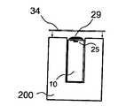
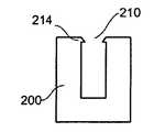
도 2a 내지 2c는 측정 샘플 취급 장치 (1)를 더욱 자세하게 도시한다. 도 2a에서 확대도가 도시되어 있고, 조립도는 도 2b에 도시되어 있으며 또 도 2c에는 소켓(110)에 부착될 수 있는 측정 샘플 취급 장치 (1)의 일부가 자세하게 도시되어 있다. 상기 측정 샘플 취급 장치 (1)은 취급 유닛 (200)을 포함할 수 있다. 도 2a 및 2c에 도시된 바와 같이, 취급 유닛 (200)은 측정 측면으로 정의된 제1 측면(202) 상에 제1 개구 (210), 및 취급 유닛 (200)의 제2 측면 (204)에 제2 개구 (220)를 갖는다. 제2 표면 (204)은, 측정 샘플 취급 장치 (1)가 상기 측정 평가 장치 (100)에 장착될 때, 측정 평가 장치 (100)의 소켓(110)을 향하여 면한다. 제1 개구 (210) 및 제2 개구 (220)는 또한 취급 유닛 (200)의 저면, 저면의 에지 및 제2표면(204)에 정렬될 수 있거나 또는 취급 유닛 (200)의 임의의 다른 측면에 정렬 될 수 있다. 개구는 측정 장치 (20)가 취급 유닛 (200)에 삽입될 수 있도록 크기가 확대될 수 있다.Figures 2a to 2c show the measured sample handling device 1 in more detail. An enlarged view is shown in Fig. 2a, an assembly drawing is shown in Fig. 2b, and in Fig. 2c a part of the measuring sample handling device 1 which can be attached to the
제1 개구 (210) 및 제2 개구 (220)는, 도 2a 및 2c에서 점선으로 도시한 바와 같이, 취급 유닛 (200) 내부에서 상호접속되어 있다.The
측정 장치 (10)은 취급 유닛 (200)의 제1 개구 (210)에 삽입된다. 측정 장치 (10)은 측정 표면 (20) 및 플러그부 (40)를 갖는다. 측정 장치 (10)는 또한, 도 9 및 도 12a,12b에 대하여 자세하게 설명되는 바와 같이, 제2 개구 (220) 또는 제3 개구 (230)를 통하여 삽입될 수 있다. 측정 표면 (20)은 측정 장치 (10)가 취급 유닛 (200)에 삽입될 때, 취급 유닛 (200)의 제1 측면(202)과 동일한 면(plane)에 실질적으로 존재한다. 따라서, 플러그부 (40)는 취급 유닛 (200)의 제2 개구 (220)를 통하여 측정 샘플 취급 장치 (1)의 외부로부터 접근할 수 있다. 측정 장치 (10)는 도 3에서 더욱 자세하게 기재되어 있다.The measuring
측정 장치 (10)은 취급 유닛 (200)과 상이한 물질로 제조될 수 있다. 특히, 측정 장치 (10)는 부분적으로 또는 전적으로 유리 물질로 제조될 수 있는 반면에, 취급 유닛 (200)은 플라스틱 물질로 제조된다.The measuring
측정 장치 (10)는 또한 중합체 물질로 제조될 수 있다.The measuring
측정 장치 (10)는 취급 유닛 (20) 보다 크기가 훨씬 작다. 따라서, 측정 장치 (10)의 밀리미터 치수가 실시되는 한편, 측정 장치 (10)는 취급 유닛 (200)과 함께 용이하게 취급될 수 있다. 취급 유닛 (200)의 크기는 사용자 (환자)의 필요에 따라서 조절될 수 있다. 예컨대, 취급 유닛 (200)은 손을 떠는 사람에게도 취급 용 이성을 제공하는 치수를 가질 수 있다. 예컨대, 취급 유닛 (200)의 크기는 적어도 하나의 치수로서 1 cm 이상, 특히 약 4 cm 이상일 수 있다. 또한, 취급 유닛 (200)의 적어도 제2 측면(204)은 소켓 (110)에 맞게 변형된다. 취급 유닛 (200)의 측면 또는 기타 기하학적 변수도 또한 소켓 (110)에 맞게 변형된다.The measuring
소켓 (110) 및 취급 유닛 (200)은 취급 유닛을 포함하는 일회용 또는 측정 샘플 취급 장치 (1)를 소켓 (110)에 삽입하는 1개의 가능성만이 존재하는 방식으로 형성될 수 있다. 따라서, 경험없는 또는 노인 사용자들 또는 환자에 의한 오작동이 배제될 수 있고 측정 오차도 피할 수 있다.The
측정 장치 (10)는 취급 유닛 (200) 내부에 삽입될 때 제2 측면(204)에 인접하게 정렬될 수 있다. 따라서, 측정 장치는, 측정 샘플 취급 장치 (1)가 소켓 (110)에 삽입될 때, 소켓(110)에 인접한다. 측정 장치 (10)는 취급 유닛 (200)의 내부에 정렬되어 플러그부 (40)를 포함하는 측정장치 (10)의 측면은, 취급 유닛 (200)에 삽입될 때, 제2 측면 (204)과 평행하게 된다.The measuring
취급 유닛 (200) 및 측정 표면 (20)은 측정 장치 (10)의 측정표면 (20)에 대한 접근을 제공하기 위해 투과성 층(32) (도 2a에 분명히 도시된 바와 같이)에 의해 덮일 수 있다. 상기 투과성 층(32)은 완전히 또는 부분적으로 측정 측면 (202) 및 측정 표면 (20)을 덮는다.The
실링 (34)은 투과성 층(32)을 실링하기 위해 측정 측면(202)에 또는 유체의 누출 또는 증발을 방지하기 위해 측정 표면 (20)의 상부에 제공된다. 실링층 (34)은 측정 장치를 사용하기 전에 환자 또는 사용자에 의해 제거될 수 있다. 투과성 층(32) 및 실링 (34)은 상이한 크기일 수 있다. 당업자들은 더 많은 또는 더 적은 층들이 측정 표면 (20)의 상부 또는 제1 표면 (202)에 정렬될 수 있음을 잘 알고 있을 것이다.A
마개 장치 (30)는 사용하기 전 및/또는 사용한 후에 측정 표면 (20)을 폐쇄하기 위해 사용될 수 있다. 실링 (34) 및 투과성 층 (32)은 측정 장치 (10), 마개 장치 (30) 또는 취급 유닛 (200)에 부착될 수 있다.The
취급 장치 (200) 및 마개 장치 (30)는 동일한 물질, 예컨대 플라스틱 물질로 제조될 수 있다. 취급 장치 (200) 및 마개 장치 (30)는 일체로 제조될 수 있다. 마개 장치부를 취급 장치부로부터 분리하기 위하여 또 측정 표면 (20)을 밀폐 또는 폐쇄하기 위하여 취급 장치의 상면에서 마개 장치의 접힘이 가능하도록 인테그랄 힌지(integral hinge)가 제공될 수 있다.The
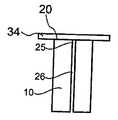
도 3a, 3b, 및 3c는 측정 장치 (10)를 사시도, 측면도 및 상면도로 각각 도시한다.Figures 3a, 3b and 3c show perspective, side and top views of the measuring
측정 장치 (10)는 측정부 (15) 내에 제1 개구 (25)를 갖는다. 미세유체성 채널 (60) (도 4에 도시됨)은 측정 장치 (10) 내부의 측정부 (15)에서 이행된다. 제1 개구 (25)는 측정 표면 (20)의 주변으로부터 미세유체성 채널 (60)로 접근을 제공한다. 당업자들은 복수의 개구 (25)가 제공될 수 있는 것과 미세유체성 채널 (60)이 측정 장치 (10)에서 실현된 상이한 채널 (60)의 네트워크를 포함할 수 있음을 잘 알고 있을 것이다. 본 발명에 특히 유용한 제1 개구 (25)를 갖는 채널 (60)의 일례는 특허출원 PCT/EP2006/011148호에서 찾아볼 수 있다. 측정 장치 (10)는 적어 도 부분적으로 유리 물질 또는 미세구조화될 수 있는 다른 물질 내에 형성된다.The measuring
제1 개구 (25)는 측정 표면 (20) 내에 있을 수 있다. 제1 개구 (25)는 액체 샘플이 적용되는 측정 표면 (20)과 매우 근접한 측정 장치 (10)의 측정부 (15)의 다른 측면에 존재할 수 있다. 이 경우, 액체 샘플은 측정 표면 (20)에서부터 제1 개구 (25)로 갈 것이다.The
플러그부 (40)는 제1 개구 (25)를 포함하는 측정 표면 (20)보다는 측정 장치 (10)의 상이한 측면에 정렬된다. 따라서, 취급 유닛 (200)에 삽입될 때, 플러그부 (40)는 취급 유닛 (200)의 제2 개구 (220)를 통해서만 접근할 수 있는 반면에, 측정 표면 (20)은 취급 유닛 (200)의 제1 개구 (210)를 통해서만 접근할 수 있다. 따라서 취급 유닛 (200)은 측정 표면 (20)에 사용되어 부가되는 액체 샘플이 복수의 전기적 접점 (50)의 어떤 것과도 접촉할 수 없도록 시일을 제공할 수 있다. 따라서, 측정장치 (10)의 작용의 측정 또는 제어를 손상시킬 수 있는 2 이상의 복수의 접점 (50) 사이의 전기적 단락 회로가 유리하게 배제될 수 있다.The
플러그부 (40) 및 측정 표면 (20)은 또한 측정 장치 (10)의 동일 측면에 정렬될 수 있다. 그러나, 플러그부 (40) 및 측정 표면 (20)은 측정 장치 (10)가 취급 유닛 (200)에 삽입될 때 취급 유닛 (200)의 실링부에 의해 서로 분리된다. 따라서, 측정 표면 (20) 상의 액체는 플러그부 (40)의 전기적 접점과 접촉하지 않게 된다.The
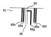
도 4는 더욱 자세히 나타낸 도 3b의 측면에서 측정 장치 (10)의 개략도를 도시한다. 미세유체성 채널 (60)은 2개의 미세유체성 저장기 (61 및 62) 사이에 정렬된다. 미세유체성 채널 (60)은 또한 측정 표면 (20)에 제1 개구 (25)를 갖는다. 제1 개구 (25)는 샘플 채널 (26)을 통하여 미세유체성 채널 (60)에 접속될 수 있다.Fig. 4 shows a schematic view of the measuring
또한, 전극 (65)은 측정 장치 (10)에 통합될 수 있다. 전극 (65)은 미세유체성 채널 (60) 내부의 샘플 중의 하전된 종을 분리하기 위한 전기영동 전극(65b 및 65c)으로서 구조화될 수 있다. 전기영동 전극 (65b)은 저장기 (61, 62, 64)의 각각에 통합될 수 있다. 저장기 (61, 62, 64)는 미세유체성 채널 (60)이 저장기 (61, 62, 64)에 대한 접근만을 제공하도록 폐쇄될 수 있다. 이렇게 하여 저장기 내부의 액체는 증발 및 가스 형성으로부터 방지된다. 저장기 (61, 62, 64)는 미세유체성 채널 (60)의 폭, 높이 또는 깊이 면에서 크기가 실질적으로 더 클 수 있다.The electrode 65 may also be integrated into the measuring
전극 (65b)의 각각은 전기적 접점 (50b, 50h 및 50g) 각각과 전기적 경로를 통하여 전기적으로 접촉한다. 따라서 미세유체성 채널 (60) 내부의 전기영동은 측정 장치 (10)가 소켓 (110)에 부착될 때 측정 평가장치 (100)에 의해 전기영동 전극(65b)의 각각에 독립적으로 전압을 인가하는 것에 의해 제어될 수 있다. 개구 전극 (65c)은 제1 개구 (25)에 통합되어 전기적 접점 (50i)과 접속될 수 있다. 개구 전극 (65c)은 이후에 설명한 바와 같이 전기영동 전극으로 또는 제어 전극으로 작용할 수 있다.Each of the
전극 (65)은 또한 미세유체성 채널 (60)의 한 부분에서 전하 농도를 측정하기 위하여 상기 미세유체성 채널 (60) 부분에서 도전성을 측정하는 도전성 전극 (65a)으로서 제공될 수 있다. 상기 도전성 전극 (65a)은 전기적 접점 (50a 및 50d)에 접속되고 그에 의해 어드레스되며 (도 4에 도시된 바와 같이) 따라서 측정 장치 (10)가 소켓 (110)에 부착될 때 측정 평가 장치 (100)에 의해 제어된다.The electrode 65 may also be provided as a
모세관 전기영동 시스템에서 전기영동 전극 (65b)은 그의 고유한 특징으로 인하여 수소 원자를 흡수할 수 있는 물질, 예컨대 팔라듐 또는 백금을 기본으로 할 수 있다. 이러한 흡착은 캐소드(cathode)로서 사용된 전기영동 전극(65b) 근처에서 가스 형성, 예컨대 수소의 형성을 방지할 수 있다.In the capillary electrophoresis system, the
팔라듐 또는 백금 물질의 사용은 캐소드로 사용된 전기영동 전극 (65b)에 유용할 수 있지만, 전극 (65)의 다른 것은 또한 동일 물질로 제조될 수 있다.The use of palladium or platinum materials may be useful for the
애노드(anode)로서 사용된 전기영동 전극 (65b) 및/또는 개구 전극 (65c)은 산소 가스 형성을 방지하도록 상이한 물질로 제조될 수 있다. 예컨대, 애노드로서 사용된 전기영동 전극 (65b)은 은/염화은 전극이거나 또는 구리로 제조될 수 있다. 상기 경우, 클로라이드 및 고체 은 또는 구리 이온이 산소 대신에 형성될 것이다.The
팔라듐, 백금, 니켈, 은/염화은 및/또는 구리 뿐만 아니라 다른 물질이 1 이상의 전극 (65)에서 혼합사용되어 각 물질의 이점을 조합할 수 있다.Other materials as well as palladium, platinum, nickel, silver / silver chloride and / or copper may be mixed in at least one electrode 65 to combine the advantages of each material.
1 이상의 전극 (65, 65a, 65b, 65c)에는 탄탈 또는 크롬과 같은 불활성 물질로부터 제조된 접착층이 제공될 수 있다.The at least one
측정 장치 (10)는 또한 온도 센서, pH 센서 및 기타 전기적으로 접촉되고 잔류 전기적 접점(50c, 50c 및 50f)에 의해 제어되는 것과 같은 전기 부품을 포함할 수 있다. 당업자들은 복수의 전기적 접점 (50, 50a 내지 50i)의 개수는 순수하게 예시적인 것이고 또 그 이상 또는 그 이하의 전기적 접점이 본 발명의 범위내에서 제공될 수 있음을 잘 알고 있을 것이다.The measuring
본 발명의 이점은 측정 장치 (10)가 와이어, 도체 및 전극과 같은 수동 전기 부품 만을 포함할 수 있는 것이다. 트랜지스터, 다이오드, 플립-플롭(flip-flops) 또는 유사한 기타 능동 전기 부품과 같은 어떠한 능동 부품도 필요하지 않다. 측정 장치 (10)는 측정 평가 장치 (100)에 의해 전기적으로 제어될 수 있다. 그러나, 센서는 일부 경우에서 능동 반도체일 수 있는 반도체 소자를 포함할 수 있는 측정 장치 (10)에 통합될 수 있다.An advantage of the present invention is that the measuring
도 5는 샘플 채널 (26)에 의해 미세유체성 채널 (60)에 접속된 측정장치 (20)의 제1 개구 (25)의 특정 구체예의 상세도를 도시한다. 또한, 제2 개구 (27)는 예컨대 유체의 증발을 방지하기 위하여 제공될 수 있다. 제2 개구 (27)는 샘플 채널 (26) 및 제1 개구 (25)에 유체적으로 접속된다. 제2 개구 (27)는 제1 개구 (25)에 비하여 크기가 실질적으로 더 클 수 있다. 크기의 차이는, 액체가 미세유체성 시스템 및 샘플 채널 (26)에 충전될 때, 제1 개구 (25) 및 제2 개구 (27) 각각에서 상이한 접촉각 (θ1) 및 (θ2)를 초래한다. 접촉각 (θ1) 및 (θ2)에서 차이는 제1 개구 (25)와 제2 개구 (27)에서 압력 차이를 초래할 것이고, 이것은 액체가 제1 개구 (25) 및 제2 개구 (27)로부터 증발하게 될 때, 제1 개구 (25)에서 본질적으로 동일 수준으로 잔류하는 액체의 수준을 초래하는 한편 증발로 인하여 제2 개구 (27)에서 액체 수준이 낮아지게 할 것이다.FIG. 5 shows a detailed view of a specific embodiment of the
당업자들은 제1 개구(25)에서 증발 거동을 변형하기 위하여 동일 크기의 상이한 개구들이 부가될 수 있음을 잘 알고 있을 것이다.Those skilled in the art will appreciate that different openings of the same size may be added to modify the evaporation behavior at the
도 6은 복수의 전기적 접점 (50)을 더욱 자세하게 도시한다. 복수의 전기적 접점 (50) 각각은 측정 장치 (10)의 플러그부 (40) 내에 형성된 구멍(hole)(42) 내부에 정렬될 수 있다. 예컨대 전기적 접점은 구멍 (42)의 저부에 제공될 수 있다. 도시된 바와 같이, 복수의 전기적 접점 (50) 각각은 별개 구멍 (42)에 위치(배치)할 수 있다. 일부 경우에서, 2 이상의 복수의 전기적 접점 (50)은 또한 1개의 구멍 (42)에서 함께 정렬될 수 있다. 일부 경우에서, 구멍 (42)은 측정 장치 (10)가 일부 작용성만을 제공하는 경우 어떠한 접점없이 제공될 수 있다. 예컨대, 도 4에 도시된 전기적 접점 (5Od, 50e 및 50f)은 더 이상의 전기 부품이 사용되지 않는다면 무시될 수 있다. 그러나, 플러그부는 소켓 (110)의 상응하는 핀에 대한 공간을 제공하는 상응하는 구멍(42)을 제공한다.6 shows the plurality of
구멍 (42)은 원형 및 원통형 또는 원추형이거나 또는 당업자들에게 공지된 다른 형상일 수 있다. 원추형은 소켓 (110)의 핀을 복수의 접점 (50) 각각에 향하게 정렬 또는 안내하기 위해 사용될 수 있다. 구멍 (42)의 다른 형상도 본 발명의 범위 내에서 실시될 수 있다.The
또한, 전기적 접점의 레이아웃 또는 배열은 다양할 수 있으며 또 도면에 도시된 선-배열에 한정되지 않는다.Also, the layout or arrangement of electrical contacts may vary and is not limited to the line-arrangement shown in the figures.
본 발명의 일개 특징은 측정 샘플 취급 장치 (1)의 모든 전기적 접점이 측정 장치 (10) 내에 정렬되는 것과 취급 유닛 (200)이 접점, 와이어 등과 같은 어떠한 전기 부품도 포함하지 않는 점이다.One feature of the present invention is that all electrical contacts of the measurement sample handling device 1 are aligned in the measuring
도 7은 측정 평가 장치 (100)의 소켓(110)을 더욱 자세하게 도시한다. 소켓 (110)은 도 1에 도시된 바와 같이 측정 평가 장치 (100)의 측벽 내에 제공될 수 있거나 또는 측정 평가 장치 (100)에 전기적으로 접속될 수 있는 분리 소켓 용기 내에 제공될 수 있다.7 shows the
소켓 (110)은 측정 샘플 취급 장치 (1)가 소켓 (110)에 삽입될 때, 복수의 핀 (120)의 적어도 일부가 복수의 접점 (50)의 적어도 1개와 전기적으로 접촉하도록 측정장치 (10)의 복수의 접점 (50)에 상응하는 패턴으로 정렬되는 복수의 핀(120)을 포함한다. 복수의 핀 (120)의 개수는 측정 장치 (10)의 접점 (50)의 개수보다 적거나, 동일하거나 또는 그 이상일 수 있다. 따라서, 동일 소켓 (110) 및 따라서 동일 측정 평가 장치 (100)가 복수의 상이한 측정 장치 (10)와 함께 사용될 수 있다. 측정 장치 (10)는 예컨대 측정장치 (10)에 통합될 온도, pH 센서 등과 같은 부가적 센서로 인하여 또는 측정 장치 (10)의 상이한 적용을 위한 상이한 개수의 전극 (65)으로 인하여 전기적 접점 (50)의 개수가 상이할 수 있다. 전기적 접점 (50)의 개수는 다양할 수 있지만, 플러그부 (40) 내의 구멍의 개수 및 형상은 측정 장치 (10)를 구비한 측정 샘플 취급 또는 측정 샘플 취급 장치 (1)가 소켓(110)에 삽입될 때 핀(120) 각각에 대한 정확한 접촉 및 위치를 제공하도록 소켓(110) 내의 핀(120)의 개수 및 형상에 맞게 변형될 수 있다.
복수의 핀 (120)은 측정 장치 (100)가 소켓 (110)에 삽입될 때 복수의 핀(120)이 복수의 전기적 접점 (50)의 각 접점과 확실하게 접촉하도록 전기적 스프링 접점으로 제조될 수 있다. 스프링 접점은 측정 장치 (10)가 소켓 (110)에 삽입되고 또 전기적 접점 (50)이 핀(120)으로 향하여 강행될 때 측정장치 (10) 상에서 손상을 감소 및 예방할 수 있다.The plurality of
복수의 핀 (120)은 도 6에 도시된 바와 같이 소켓 (110) 내부에 정렬될 수 있다. 따라서, 측정 샘플 취급 장치 (1) 또는 측정 장치 (10)가 소켓 (110)에 도입될 때, 측정 장치 (10)는 완전히 또는 부분적으로 소켓 (110) 내부에 위치하게 된다. 이 경우, 측정이 개시된 후에는 측정 표면 상의 샘플에 대한 어떠한 변형도 가능하지 않고 또 취급 유닛 (200)에서 어떠한 전기적 접점도 필요하지 않은 한편 측정 장치 (10)는 작게 유지하므로 저렴하다.The plurality of
또한, 환자 또는 다른 사용자와의 직접적인 전기 접속이 불가능하다. 따라서, 측정 장치는 특수한 훈련이나 주의없이도 환자 또는 기타 사용자가 안전하게 사용할 수 있다. 이것은 샘플을 측정하는 동안 1000 볼트 주변의 고전압이 이용되기 때문에 아주 중요하다.Also, direct electrical connection with the patient or other user is not possible. Therefore, the measuring device can be safely used by the patient or other users without special training or care. This is very important because high voltages around 1000 volts are used during sample measurement.
측정 평가 장치 (100)는 측정 장치 (10)를 갖는 측정 샘플 취급 장치 (1)가 소켓(110)에 삽입될 때에만 측정을 개시할 수 있다. 예컨대, 측정은 접점 (50a) 내지 (50i) 중의 필요한 접점이 상응하는 핀과 실제로 접촉할 때에만 개시될 수 있다.The
실제 측정은 측정 장치 (10)의 정확한 작동을 위하여 성공적인 제어 측정이 실시된 후에만 개시될 수 있다. 제어 측정은 액체 샘플 (5) 중의 나트륨 농도를 측정하는 것일 수 있다. 나트륨 농도는 리튬 농도의 실제 측정과 실질적으로 평행하게 측정되고 평가될 수 있다. 성공적인 제어 측정을 위하여, 나트륨 농도는 혈액에서 흔히 발견되는 농도 범위에 들어야 한다. 상이한 나트륨 농도를 평가하는 경우, 측정에서 잘못이 있으면 평가된 리튬 농도가 정확하다고 확정할 수 없다. 그러므로 그 측정은 무시될 것이다.The actual measurement may only be initiated after a successful control measurement has been performed for the correct operation of the measuring
예컨대 나트륨 농도의 정확도를 확인하기 위하여 배경 전해질 용액 (BGE)의 도전성 또는 온도를 측정하여 부가적 및 초기 제어를 실시할 수 있다.Additional and initial control can be performed, for example, by measuring the conductivity or temperature of the background electrolyte solution (BGE) to ascertain the accuracy of the sodium concentration.
도 8a는 도 2a 내지 도 2c에 대하여 상기에 자세히 기재된 취급 유닛 (200)에 통합된 핑거 팁 배치 도구(finger tip positioning tool)를 갖는 본 발명의 특정 구체예를 도시한다. 림(rim) (212)은 취급 유닛 (200)의 측정 측면 (202) 내의 제1 개구 (210)의 1 이상의 측면 상에 제공된다. 림 (212)은, 측정 측면 (202)의 상부에 손을 놓을 때, 측정 샘플 취급 장치 (1)를 사용하는 사용자 (환자)에 의해 용이하게 감각되고 및/또는 보여질 수 있는 형상 및 높이를 갖는다. 림 (212)은 측정 장치 (10)가 취급 유닛 (200)에 삽입될 때 개구 (25)가 위치한 위치 주변의 제1 개구 (210)를 따라 정렬될 수 있다. 림 (212)은 사용자의 손 끝에 의해 감각될 수 있거나 또는 림이 눈에 간편하게 보여질 수 있기 때문에 측정 표면 (20)에 있는 개구 (25) 위로 액체 또는 혈액 샘플을 침적하기 위한 위치화 도구로서 작용할 수 있다. 이것은 개구 (25) 자체가 사용자 (환자)의 눈에 보이기에는 너무 적을 수 있기 때문에 특히 유용하다.FIG. 8A illustrates a specific embodiment of the present invention having a finger tip positioning tool incorporated in the
측정 표면 (20) 중의 공동(cavity) 또는 홈(groove) 또한 위치화 도구로서 이용될 수 있다. 공동 또는 홈은 또한 공동 또는 홈이 샘플 액체에 대한 수집기로서 작용하고 또 샘플 액체가 측정 장치 밖으로 누출되거나 퍼져나가지 않게 할 수 있는 다른 이점을 갖는다.A cavity or groove in the measuring
도 4 또는 도 8b에 도시된 바와 같이 제1 개구 (25)에 존재하는 개구 전극 (56c)은 제1 개구 (25) 주변에서 샘플 액체의 존재를 검출하기 위해 이용될 수 있다. 예컨대, 개구 전극 (65c)은 공동 또는 홈 위치 내에서 특정 위치 또는 높이로 존재할 수 있다. 따라서 샘플 액체 (5)의 존재, 및 또한 특정 양의 샘플 액체의 존재는 신뢰성 있는 측정을 위해 필요로 하는 필요 양의 샘플 액체가 부가되었음이 확실하도록 확인될 수 있다.As shown in FIG. 4 or 8B, an opening electrode 56c present in the
도 8b는 제1 개구 (25)에서 부가적 전극이 어떻게 정렬될 수 있는지에 대한 예를 도시한다. 개구 전극 (65c) 이외에, 적어도 1개의 제어 전극 (65d, 65e, 및 65f)이 사용될 수 있다. 적어도 1개의 제어 전극 (65d, 65e, 65f)은 액체 샘플의 도전성과 같은 부가적 변수를 측정하기 위하여 제1 개구 (25)와 인접하게 정렬될 수 있다. 예컨대, 액체 샘플의 도전성은 제어 전극 (65d) 및 제어 전극 (65e) 사이에서 측정될 수 있다. 전극 (65f)은 상이한 원료로 제조될 수 있거나 또는 액체 샘플의 상이한 변수를 측정하기 위한 코팅을 가질 수 있다.8B shows an example of how additional electrodes can be aligned in the
채널 전극 (65g)은 제1 개구 (25)와 근접하게 제공될 수 있다. 채널 전극 (65g)은, 샘플 채널이 전해질 용액으로 충전될 때, 샘플 채널 (26) 내부의 용액과 접촉한다. 전해질 용액의 증발이 일어나야 하는 경우, 전해질 용액의 수준은 채널 전극 (65g) 아래로 가라앉을 것이고, 이것은 도전성 측정에 의해 용이하게 검출될 수 있다.The
채널 전극 (65g) 뿐만 아니라 개구 전극 (65c) 및 제어 전극 (65d, 65e, 및 65f)은 초기 도전성 또는 증발 및/또는 가스 기포 검출에 대한 표시로서 초기 제어 측정에 사용될 수 있다.The
개구 전극 (65c) 또는 제어 전극 (65d, 65e 또는 65f) 또는 채널 전극 (65g)은 예컨대 샘플 채널 (26) 내부의 모세관 전기영동용의 전기영동 전극으로서 이용될 수 있다.The
도 9는 삽입된 측정 장치 (10)를 갖는 취급 유닛 (200)의 단면도를 도시한다. 사용하기 전, 실링 점적 (29)은 개구 (25)의 적어도 상면에 위치할 수 있다. 실링 점적 (29)은 실리콘, PDMS 또는 다른 물질로 제조될 수 있고 또 따라서 증발 및 오염을 방지하기 위하여 개구 (25) 및 미세유체성 채널 (60)을 덮는다. 도 2a와 관련하여 상기 기재한 실링 (34)은 사용하기 전 측정 표면을 덮기 위한 점착성 호일일 수 있다. 실링 점적 (29)은 점착성 호일에 점착될 수 있다. 사용자 (환자)는 점착성 호일을 제거할 수 있고 또 동시에 실링 점적 (29)은 그것에 점착되어 개구 (25)에 대한 접근을 제공한다.Figure 9 shows a cross-sectional view of the
도 10a 내지 10c는 측정 장치 (10)의 제1 개구 (25) 상에서 실링 (34) 및 실링 점적 (29)의 상이한 배열을 도시한다. 도 10a에 도시된 바와 같이, 실리콘 물질 등으로 제조될 수 있는 실링 점적 (29)은 측정 장치 (10)를 사용하기 전에 액체에 의해 충전된 미세유체성 채널 (60) 및 샘플 채널 (26)을 포함하는 미세유체성 네트워크 후에 제1 개구 (25) 상에 위치할 수 있다. 따라서 실링 점적 (29)은 액체가 제1 개구 (25)를 통하여 미세유체성 네트워크로부터 증발되지 않게 한다. 예컨대 테이프 또는 호일 형태의 다른 실링 (34)이 실링 점적 (29)의 상부에 도포될 수 있다. 환자 또는 사용자가 측정 장치 (10)를 사용하고 싶을 때, 액체 샘플 (5)을 제1 개구 (25)에 도포하기 전에 실링 (34) 및 실링 점적 (29)을 제거한다. 실링 점적 (29)은 그의 제거를 용이하게 하기 위하여 실링(34)에 부착될 수 있다.10a to 10c show different arrangements of the sealing 34 and the sealing
실링 (34)은 또한 도 10b에 도시된 바와 같이, 실링 (34)이 측정 장치 (10)의 측정 표면 (20) 상에 위치할 때, 제1 개구 (25)의 상면에 실질적으로 정렬된 구멍(35)을 포함할 수 있다. 상기 경우, 실링 점적 (29)은 부착을 확실히 하기 위해 실링(34) 내의 구멍(35)을 통하여 연장될 수 있다. 따라서 실링 점적 (29)은 측정장치 (10)를 사용하기 전에 사용자 또는 환자가 실링 (34)을 제거할 때 제1 개구 (25)로부터 제거된다.The
실링 (34)은 측정 장치 (10)의 측정 표면 (20)에 직접 부착될 수 있다. 실링 (34)은 제1 개구 (25)를 직접 실링할 수 있다. 실링은 실리콘 또는 기타 적합한 물질에 의해 제조되거나 덮히는 테이프 또는 호일일 수 있다.The sealing 34 may be attached directly to the measuring
실링 (34) 및 결국 실링 점적 (29)은 마개 장치 (30)에 부착될 수 있다. 상기 경우, 실링은 측정 장치 (10)를 사용하기 전에 마개 장치 (30)를 개방할 때 제거된다. 실링은 또한, 액체 샘플 (5)의 오염 및 증발을 예방하기 위하여 측정 표면 (20) 상에 액체 샘플 (5)을 배치한 후 마개 장치 (30)를 폐쇄할 때, 도포될 수 있다.The
당업자들은 제1 개구 (25)에 대하여 상기 기재된 실링 (34)은 측정장치 (10) 중의 다른 개구, 예컨대 도 5에 상세하게 기재된 제2 개구 (27)에 도포될 수 있다.Those skilled in the art can apply the
도 11은 취급 유닛 (200) 내에 측정 장치 (10)를 고정하기 위한 록킹 장치(214)를 갖는 본 발명의 취급 유닛 (200)을 도시한다. 상기 측정 장치 (10)는 도 2a에 도시된 바와 같이, 제1 개구 (210)를 통하여 취급 유닛 (200)에 삽입될 수 있다. 림 형태의 록킹 장치 (214)는 개구 (210)에서 제공될 수 있다. 따라서, 적어도 1 방향에서 개구 (210)의 폭은 측정 장치 (10)의 상응하는 크기보다 약간 작거나 또는 동일할 수 있다. 록킹 장치 (214)는 취급 유닛 (200) 내에 측정 장치 (10)에 대한 고정 또는 스냅-인(snap-in) 메카니즘으로 작용할 수 있다.Figure 11 shows the
도 12a 및 12b는 취급 유닛 (200)에 제공된 제3 개구 (230)를 통하여 취급 유닛 (200)에 측정 장치 (10)를 삽입하는 것을 도시한다. 제3 개구는 취급 유닛 (200)의 제1 측면(202)에 대한 대향 측면 상에 제공될 수 있다. 따라서, 취급 유닛 (200) 내의 제1 개구 (210)은 크기가 작을 수 있고 또 본질적으로 측정 표면 (20) 상의 제1 개구 (25)에 대하여만 접근을 제공한다. 이렇게 하여, 샘플 액체가 플러그부 (40)와 접촉하지 않게 방지하기 위한 접촉 시일은 크기에서 실질적으로 대형일 수 있다. 또한, 측정 표면 (20) 및 제1 개구 (25)의 배치(positioning)는 더욱 정확하게 실시될 수 있다.Figures 12A and 12B illustrate the insertion of the measuring
제3 개구 (230)는 또한 제2 개구 (220)와 조합되어 플러그부 (40) 및 측정장치 (10)의 삽입을 위한 1개의 확대된 개구를 형성한다.The
스냅-인 메카니즘일 수 있는 록킹 장치 (234)는 도 12b에 도시된 바와 같이, 측정장치 (10)의 고정 및 정확한 위치 선정을 확실히 하기 위하여 취급 유닛 (200) 및/또는 측정 장치 (10)에 제공될 수 있다. 시일 (34), 투과성 층(32) 또는 취급 유닛 (200)에 제공된 기타 수단은, 오염 및 증발을 방지하기 위하여 제1 개구 (25)의 폐쇄를 확실히 하도록 측정장치 (10)가 삽입될 때에 대한 저항력을 제공할 수 있다.The
도 13은 마개 장치 (30)를 갖는 취급 유닛 (200)을 폐쇄하기 위한 록킹 메카니즘을 도시한다. 상기 마개 장치 (30)는 후크(38)를 갖게 제공될 수 있으며, 이것은 특히 액체 샘플이 측정 장치 (10)의 개구 (25) 상에 배치된 후 측정 표면 (20) 및 개구 (25)를 덮어 보호하기 위하여 취급 유닛 (200)의 제1 표면(202) 상에 마개 장치 (30)가 위치될 때, 취급 유닛 (200)에서 상응하는 노치(238)와 체결(engage)될 수 있다. 후크 (38) 및 노치 (238)는 비-제거 방식으로 서로에 대해 체결될 수 있어 스냅-인 록킹 장치를 형성한다. 상기 경우, 마개 장치 (30)를 폐쇄한 후, 취급 유닛 (200)은 재개방될 수 없으므로 재사용될 수 없다. 이것은 샘플의 오염뿐만 아니라 측정 결과의 오류를 방지한다.Fig. 13 shows a locking mechanism for closing the
스냅-인 또는 록킹 메카니즘은 본 발명에 따라 사용될 수 있음은 분명하다. 예컨대, 록킹 메카니즘은 측정 표면에 대하여 복수의 접근을 허용하도록 개폐될 수 있는 메카니즘으로서 제공될 수 있다. 이러한 메카니즘은 흔히 공지되어 있고 널리 사용되고 있다.It is clear that a snap-in or locking mechanism can be used in accordance with the present invention. For example, the locking mechanism can be provided as a mechanism that can be opened and closed to allow multiple accesses to the measurement surface. Such a mechanism is commonly known and widely used.
본 발명은 몇 개 구체예를 들어 기재하였다. 그러나, 당업자라면 본 발명이 이들에 한정되지 않음을 잘 알 것이다. 오히려 본 발명의 범위는 이하의 특허청구범위와 함께 이해되어야 한다.The present invention has been described in several embodiments. However, those skilled in the art will recognize that the present invention is not limited thereto. Rather, the scope of the present invention should be understood in conjunction with the following claims.
Claims (73)
Translated fromKoreanApplications Claiming Priority (1)
| Application Number | Priority Date | Filing Date | Title |
|---|---|---|---|
| PCT/EP2007/004468WO2008141659A1 (en) | 2007-05-18 | 2007-05-18 | Test chip with plug for measuring the concentration of an analyte in a liquid, housing for test chip and socket for plug |
Related Child Applications (2)
| Application Number | Title | Priority Date | Filing Date |
|---|---|---|---|
| KR1020137011249ADivisionKR101366487B1 (en) | 2007-05-18 | 2007-05-18 | Microfluidic Measurement Device |
| KR1020137011248ADivisionKR101401711B1 (en) | 2007-05-18 | 2007-05-18 | A Measurement Sample Handling Device with a Sealed, Solution-Filled Channel |
Publications (2)
| Publication Number | Publication Date |
|---|---|
| KR20100005207A KR20100005207A (en) | 2010-01-14 |
| KR101346468B1true KR101346468B1 (en) | 2014-01-02 |
Family
ID=38617428
Family Applications (3)
| Application Number | Title | Priority Date | Filing Date |
|---|---|---|---|
| KR1020097023090AExpired - Fee RelatedKR101346468B1 (en) | 2007-05-18 | 2007-05-18 | Test chip with plug for measuring the concentration of an analyte in a liquid, housing for test chip and socket for plug |
| KR1020137011248AExpired - Fee RelatedKR101401711B1 (en) | 2007-05-18 | 2007-05-18 | A Measurement Sample Handling Device with a Sealed, Solution-Filled Channel |
| KR1020137011249AExpired - Fee RelatedKR101366487B1 (en) | 2007-05-18 | 2007-05-18 | Microfluidic Measurement Device |
Family Applications After (2)
| Application Number | Title | Priority Date | Filing Date |
|---|---|---|---|
| KR1020137011248AExpired - Fee RelatedKR101401711B1 (en) | 2007-05-18 | 2007-05-18 | A Measurement Sample Handling Device with a Sealed, Solution-Filled Channel |
| KR1020137011249AExpired - Fee RelatedKR101366487B1 (en) | 2007-05-18 | 2007-05-18 | Microfluidic Measurement Device |
Country Status (9)
| Country | Link |
|---|---|
| US (1) | US9410924B2 (en) |
| EP (2) | EP2565640B1 (en) |
| JP (1) | JP5237359B2 (en) |
| KR (3) | KR101346468B1 (en) |
| CN (1) | CN101711359A (en) |
| BR (1) | BRPI0721675A2 (en) |
| CA (1) | CA2685361C (en) |
| EA (1) | EA200901553A1 (en) |
| WO (1) | WO2008141659A1 (en) |
Families Citing this family (5)
| Publication number | Priority date | Publication date | Assignee | Title |
|---|---|---|---|---|
| USD604302S1 (en) | 2008-04-02 | 2009-11-17 | Medimate Holding B.V. | Housing for test chip |
| KR102316022B1 (en)* | 2015-01-30 | 2021-10-21 | 휴렛-팩커드 디벨롭먼트 컴퍼니, 엘.피. | Fluid Test Chips and Cassettes |
| DK3502231T3 (en)* | 2017-12-19 | 2020-10-12 | Eppendorf Ag | BIOPROCESS CONTROL DEVICE AND BIOPROCESS SYSTEM |
| US11219642B1 (en)* | 2020-09-01 | 2022-01-11 | Catherine Lueninghoener | Methods and compositions for treating heart conditions |
| KR102618172B1 (en)* | 2020-12-24 | 2023-12-29 | 경북대학교 산학협력단 | Measuring system of electrical properties of liquid and method for the measuring electrical properties of liquid |
Citations (2)
| Publication number | Priority date | Publication date | Assignee | Title |
|---|---|---|---|---|
| US5955028A (en)* | 1996-08-02 | 1999-09-21 | Caliper Technologies Corp. | Analytical system and method |
| US5989402A (en)* | 1997-08-29 | 1999-11-23 | Caliper Technologies Corp. | Controller/detector interfaces for microfluidic systems |
Family Cites Families (64)
| Publication number | Priority date | Publication date | Assignee | Title |
|---|---|---|---|---|
| US3506554A (en) | 1968-03-15 | 1970-04-14 | Samuel Raymond | Apparatus for separating electrophoretically active substances |
| DE2852978C3 (en) | 1978-12-07 | 1981-06-04 | Raimund Dr. 4005 Meerbusch Kaufmann | Device for the spectroscopic determination of the speed of particles moving in a liquid |
| FR2496889A1 (en) | 1980-12-22 | 1982-06-25 | Hours Michel | MIGRATION AND REACTION TANK USED FOR ELECTROPHORESIS ANALYZES |
| CA1292176C (en) | 1985-09-18 | 1991-11-19 | Joel M. Blatt | Volume metering capillary gap device for applying a liquid sample onto a reactive surface |
| JPS6396453U (en) | 1986-12-11 | 1988-06-22 | ||
| CA1339779C (en)* | 1987-06-17 | 1998-03-24 | Xiao-Hua Huang | On-column conductivity detector for microcolumn electrokinetic separations |
| US5223114A (en) | 1987-06-17 | 1993-06-29 | Board Of Trustees Of The Leland Stanford Junior University | On-column conductivity detector for microcolumn electrokinetic separations |
| JPH0682114B2 (en) | 1988-04-14 | 1994-10-19 | 工業技術院長 | Lithium ion sensor |
| US5096669A (en) | 1988-09-15 | 1992-03-17 | I-Stat Corporation | Disposable sensing device for real time fluid analysis |
| JP2657130B2 (en) | 1991-06-28 | 1997-09-24 | 三洋電機株式会社 | Clothes dryer |
| DE69333601T2 (en) | 1993-04-15 | 2005-09-15 | Zeptosens Ag | Method of controlling sample introduction in microseparation techniques and sampling devices |
| CA2123940A1 (en) | 1993-06-21 | 1994-12-22 | Philip A. Guadagno | Electrophoresis plate |
| CA2704228C (en) | 1995-03-10 | 2013-10-22 | Meso Scale Technologies, Llc | Multi-array, multi-specific electrochemiluminescence testing |
| US5800692A (en) | 1995-04-17 | 1998-09-01 | Mayo Foundation For Medical Education And Research | Preseparation processor for use in capillary electrophoresis |
| US5849208A (en)* | 1995-09-07 | 1998-12-15 | Microfab Technoologies, Inc. | Making apparatus for conducting biochemical analyses |
| US5882496A (en) | 1997-02-27 | 1999-03-16 | The Regents Of The University Of California | Porous silicon structures with high surface area/specific pore size |
| JP3711391B2 (en) | 1997-03-12 | 2005-11-02 | アークレイ株式会社 | Test device for analyzing liquid samples |
| JPH1158342A (en) | 1997-05-23 | 1999-03-02 | Sekisui Chem Co Ltd | Forming die for alkaline material, and forming method for alkaline material |
| US5900130A (en) | 1997-06-18 | 1999-05-04 | Alcara Biosciences, Inc. | Method for sample injection in microchannel device |
| JP3297630B2 (en)* | 1997-07-28 | 2002-07-02 | 松下電器産業株式会社 | Biosensor |
| US6979424B2 (en) | 1998-03-17 | 2005-12-27 | Cepheid | Integrated sample analysis device |
| US6444474B1 (en)* | 1998-04-22 | 2002-09-03 | Eltron Research, Inc. | Microfluidic system for measurement of total organic carbon |
| FR2779525B1 (en)* | 1998-06-08 | 2000-10-13 | Claude Hanni | APPARATUS FOR MEASURING THE ELECTROPHYSIOLOGICAL ACTIVITY OF A CLUSTER OF CELLS |
| JP2000002677A (en) | 1998-06-15 | 2000-01-07 | Asahi Chem Ind Co Ltd | Analyzer |
| BR9914554A (en) | 1998-10-13 | 2001-06-26 | Biomicro Systems Inc | Fluid circuit components based on passive fluid dynamics |
| US6261431B1 (en) | 1998-12-28 | 2001-07-17 | Affymetrix, Inc. | Process for microfabrication of an integrated PCR-CE device and products produced by the same |
| JP2000227414A (en) | 1999-02-08 | 2000-08-15 | Shimadzu Corp | Chip unit for microchip electrophoresis |
| KR100297693B1 (en) | 1999-04-20 | 2001-10-29 | 김순택 | Electrode assembly of electron gun for CRT |
| US6555389B1 (en) | 1999-05-11 | 2003-04-29 | Aclara Biosciences, Inc. | Sample evaporative control |
| CA2308532C (en)* | 1999-05-12 | 2005-11-29 | Gador S.A. | Use of bisphosphonates for the treatment of osteogenesis imperfecta |
| JP3847053B2 (en) | 2000-03-15 | 2006-11-15 | 純 菊地 | Blood analyzer |
| EP1269141A4 (en)* | 2000-04-06 | 2003-09-10 | Caliper Techn Corp | Microfluidic devices and systems incorporating cover layers |
| DE60140553D1 (en)* | 2000-09-14 | 2009-12-31 | Caliper Life Sciences Inc | MICROFLUIDIC DEVICES AND METHODS FOR CARRYING OUT TEMPERATURE-MEDIATED REACTIONS |
| WO2002072264A1 (en)* | 2001-03-09 | 2002-09-19 | Biomicro Systems, Inc. | Method and system for microfluidic interfacing to arrays |
| ATE543091T1 (en) | 2001-08-01 | 2012-02-15 | Arkray Inc | ANALYZER, ANALYZER |
| US20050150766A1 (en) | 2001-11-02 | 2005-07-14 | Andreas Manz | Capillary electrophoresis microchip system and method |
| US6864480B2 (en)* | 2001-12-19 | 2005-03-08 | Sau Lan Tang Staats | Interface members and holders for microfluidic array devices |
| US7419821B2 (en) | 2002-03-05 | 2008-09-02 | I-Stat Corporation | Apparatus and methods for analyte measurement and immunoassay |
| AU2003234419A1 (en) | 2002-05-13 | 2003-11-11 | The Regents Of The University Of Michigan | Method of forming manofluidic channels |
| JP4152126B2 (en)* | 2002-05-31 | 2008-09-17 | 株式会社日立ハイテクノロジーズ | Electrophoresis device |
| JP2004020367A (en) | 2002-06-17 | 2004-01-22 | Arkray Inc | Analyzing apparatus |
| US7452507B2 (en)* | 2002-08-02 | 2008-11-18 | Sandia Corporation | Portable apparatus for separating sample and detecting target analytes |
| US7111502B2 (en) | 2002-08-06 | 2006-09-26 | Ocusense, Inc. | Systems and methods for reducing the effect of corruptive signals during nanoliter osmometry |
| FR2844052B1 (en) | 2002-08-28 | 2005-07-01 | Commissariat Energie Atomique | DEVICE FOR MEASURING THE ELECTRIC ACTIVITY OF BIOLOGICAL ELEMENTS AND ITS APPLICATIONS |
| JP3803078B2 (en) | 2002-09-20 | 2006-08-02 | 独立行政法人科学技術振興機構 | Hematology analyzer and plasma separation method |
| US20040086872A1 (en)* | 2002-10-31 | 2004-05-06 | Childers Winthrop D. | Microfluidic system for analysis of nucleic acids |
| US7108775B2 (en)* | 2002-11-08 | 2006-09-19 | Applera Corporation | Apparatus and method for confining eluted samples in electrophoresis systems |
| KR100554649B1 (en) | 2003-06-09 | 2006-02-24 | 주식회사 아이센스 | Electrochemical Biosensor |
| US20040265172A1 (en) | 2003-06-27 | 2004-12-30 | Pugia Michael J. | Method and apparatus for entry and storage of specimens into a microfluidic device |
| RU2006110931A (en)* | 2003-09-05 | 2007-10-20 | Кайлипер Лайф Сайенсиз, Инк. (Us) | ANALYZED SUBSTANCE INJECTION SYSTEM |
| JP4345888B2 (en) | 2003-10-29 | 2009-10-14 | グンゼ株式会社 | Measurement display |
| DE10359303A1 (en) | 2003-12-17 | 2005-07-21 | Roche Diagnostics Gmbh | Plastic injection molded part with embedded component |
| DE102004020829B4 (en) | 2004-04-28 | 2006-05-18 | Fraunhofer-Gesellschaft zur Förderung der angewandten Forschung e.V. | Sensor for the detection of ingredients of liquids, in particular biological materials, and detection device containing this sensor |
| JP4492212B2 (en) | 2004-05-20 | 2010-06-30 | 株式会社島津製作所 | Isoelectric focusing chip and apparatus |
| JP4881034B2 (en) | 2005-02-28 | 2012-02-22 | 富士フイルム株式会社 | Electronic album editing system, electronic album editing method, and electronic album editing program |
| DE202005009960U1 (en)* | 2005-06-24 | 2005-09-01 | Forschungszentrum Karlsruhe Gmbh | Measurement unit, for capillary electrophoresis, has a capillary array in a micro-fluid chip within a box with conductive walls, a high tension supply and a high frequency transmitter/receiver for non-contact conductivity detection |
| JP4740664B2 (en) | 2005-07-04 | 2011-08-03 | パナソニック株式会社 | Microbial test chip and microbiological test method |
| JP2007064742A (en) | 2005-08-30 | 2007-03-15 | Nec Corp | Chemical chip and connection device |
| US7799195B2 (en) | 2005-09-02 | 2010-09-21 | Vladislav Dolnik | Neutral polysaccharide wall coating for electrophoretic separations in capillaries and microchannels |
| US7938573B2 (en)* | 2005-09-02 | 2011-05-10 | Genefluidics, Inc. | Cartridge having variable volume reservoirs |
| US20070065346A1 (en)* | 2005-09-19 | 2007-03-22 | Henry Lauren R | Micro-fluidic device with neutralization and neutralization methods |
| WO2008049447A1 (en)* | 2006-10-25 | 2008-05-02 | Fraunhofer-Gesellschaft Zur Foerderung Der Angewandten Forschung E.V. | Chip holder, fluidic system and chip holder system |
| CN101568828B (en)* | 2006-11-21 | 2013-10-23 | 麦迪美特控股有限公司 | Ion sensor for liquid and manufacturing method thereof |
| ES2687620T3 (en)* | 2007-05-04 | 2018-10-26 | Opko Diagnostics, Llc | Device and method for analysis in microfluidic systems |
- 2007
- 2007-05-18KRKR1020097023090Apatent/KR101346468B1/ennot_activeExpired - Fee Related
- 2007-05-18CNCN200780052977Apatent/CN101711359A/enactivePending
- 2007-05-18KRKR1020137011248Apatent/KR101401711B1/ennot_activeExpired - Fee Related
- 2007-05-18EPEP12183415.4Apatent/EP2565640B1/ennot_activeNot-in-force
- 2007-05-18USUS12/600,738patent/US9410924B2/enactiveActive
- 2007-05-18JPJP2010507797Apatent/JP5237359B2/enactiveActive
- 2007-05-18WOPCT/EP2007/004468patent/WO2008141659A1/enactiveApplication Filing
- 2007-05-18CACA2685361Apatent/CA2685361C/ennot_activeExpired - Fee Related
- 2007-05-18EPEP07725376.3Apatent/EP2150815B1/ennot_activeWithdrawn - After Issue
- 2007-05-18KRKR1020137011249Apatent/KR101366487B1/ennot_activeExpired - Fee Related
- 2007-05-18EAEA200901553Apatent/EA200901553A1/enunknown
- 2007-05-18BRBRPI0721675-0Apatent/BRPI0721675A2/ennot_activeIP Right Cessation
Patent Citations (2)
| Publication number | Priority date | Publication date | Assignee | Title |
|---|---|---|---|---|
| US5955028A (en)* | 1996-08-02 | 1999-09-21 | Caliper Technologies Corp. | Analytical system and method |
| US5989402A (en)* | 1997-08-29 | 1999-11-23 | Caliper Technologies Corp. | Controller/detector interfaces for microfluidic systems |
Also Published As
| Publication number | Publication date |
|---|---|
| KR20130051515A (en) | 2013-05-20 |
| BRPI0721675A2 (en) | 2013-01-22 |
| KR101401711B1 (en) | 2014-05-30 |
| KR20100005207A (en) | 2010-01-14 |
| EP2565640A1 (en) | 2013-03-06 |
| EP2565640B1 (en) | 2016-09-14 |
| US20100236926A1 (en) | 2010-09-23 |
| CA2685361C (en) | 2014-05-06 |
| JP2010527444A (en) | 2010-08-12 |
| EA200901553A1 (en) | 2010-04-30 |
| US9410924B2 (en) | 2016-08-09 |
| JP5237359B2 (en) | 2013-07-17 |
| WO2008141659A1 (en) | 2008-11-27 |
| EP2150815A1 (en) | 2010-02-10 |
| CA2685361A1 (en) | 2008-11-27 |
| KR20130051516A (en) | 2013-05-20 |
| EP2150815B1 (en) | 2014-12-03 |
| KR101366487B1 (en) | 2014-02-21 |
| CN101711359A (en) | 2010-05-19 |
Similar Documents
| Publication | Publication Date | Title |
|---|---|---|
| US10932761B2 (en) | Advanced sweat sensor adhesion, sealing, and fluidic strategies | |
| CN101568828B (en) | Ion sensor for liquid and manufacturing method thereof | |
| KR101346468B1 (en) | Test chip with plug for measuring the concentration of an analyte in a liquid, housing for test chip and socket for plug | |
| JP7196162B2 (en) | Microfluidic device with laterally insertable electrodes | |
| RU2515207C2 (en) | Device to measure concentration of charged particles | |
| EP2562537B1 (en) | Liquid sample test method and device with test chip and handling unit | |
| JP2013137327A (en) | Micro fluid type measuring device | |
| JP2013156268A (en) | Measurement sample handling device having channel filled with liquid and sealed | |
| JP2014160095A (en) | Device for measuring concentration of charged specie in sample | |
| HK1218952A1 (en) | Washable analyte meters, sealed connectors, and methods of manufacturing and using same | |
| CN104155356A (en) | Device for measuring concentration of charged species in sample |
Legal Events
| Date | Code | Title | Description |
|---|---|---|---|
| A201 | Request for examination | ||
| PA0105 | International application | St.27 status event code:A-0-1-A10-A15-nap-PA0105 | |
| PA0201 | Request for examination | St.27 status event code:A-1-2-D10-D11-exm-PA0201 | |
| P11-X000 | Amendment of application requested | St.27 status event code:A-2-2-P10-P11-nap-X000 | |
| P13-X000 | Application amended | St.27 status event code:A-2-2-P10-P13-nap-X000 | |
| R15-X000 | Change to inventor requested | St.27 status event code:A-3-3-R10-R15-oth-X000 | |
| R16-X000 | Change to inventor recorded | St.27 status event code:A-3-3-R10-R16-oth-X000 | |
| AMND | Amendment | ||
| E13-X000 | Pre-grant limitation requested | St.27 status event code:A-2-3-E10-E13-lim-X000 | |
| P11-X000 | Amendment of application requested | St.27 status event code:A-2-2-P10-P11-nap-X000 | |
| P13-X000 | Application amended | St.27 status event code:A-2-2-P10-P13-nap-X000 | |
| PG1501 | Laying open of application | St.27 status event code:A-1-1-Q10-Q12-nap-PG1501 | |
| E902 | Notification of reason for refusal | ||
| PE0902 | Notice of grounds for rejection | St.27 status event code:A-1-2-D10-D21-exm-PE0902 | |
| T11-X000 | Administrative time limit extension requested | St.27 status event code:U-3-3-T10-T11-oth-X000 | |
| AMND | Amendment | ||
| P11-X000 | Amendment of application requested | St.27 status event code:A-2-2-P10-P11-nap-X000 | |
| P13-X000 | Application amended | St.27 status event code:A-2-2-P10-P13-nap-X000 | |
| E902 | Notification of reason for refusal | ||
| PE0902 | Notice of grounds for rejection | St.27 status event code:A-1-2-D10-D21-exm-PE0902 | |
| T11-X000 | Administrative time limit extension requested | St.27 status event code:U-3-3-T10-T11-oth-X000 | |
| T11-X000 | Administrative time limit extension requested | St.27 status event code:U-3-3-T10-T11-oth-X000 | |
| AMND | Amendment | ||
| E13-X000 | Pre-grant limitation requested | St.27 status event code:A-2-3-E10-E13-lim-X000 | |
| P11-X000 | Amendment of application requested | St.27 status event code:A-2-2-P10-P11-nap-X000 | |
| P13-X000 | Application amended | St.27 status event code:A-2-2-P10-P13-nap-X000 | |
| E902 | Notification of reason for refusal | ||
| PE0902 | Notice of grounds for rejection | St.27 status event code:A-1-2-D10-D21-exm-PE0902 | |
| T11-X000 | Administrative time limit extension requested | St.27 status event code:U-3-3-T10-T11-oth-X000 | |
| A107 | Divisional application of patent | ||
| AMND | Amendment | ||
| E13-X000 | Pre-grant limitation requested | St.27 status event code:A-2-3-E10-E13-lim-X000 | |
| P11-X000 | Amendment of application requested | St.27 status event code:A-2-2-P10-P11-nap-X000 | |
| P13-X000 | Application amended | St.27 status event code:A-2-2-P10-P13-nap-X000 | |
| PA0104 | Divisional application for international application | St.27 status event code:A-0-1-A10-A18-div-PA0104 St.27 status event code:A-0-1-A10-A16-div-PA0104 | |
| E601 | Decision to refuse application | ||
| PE0601 | Decision on rejection of patent | St.27 status event code:N-2-6-B10-B15-exm-PE0601 | |
| T11-X000 | Administrative time limit extension requested | St.27 status event code:U-3-3-T10-T11-oth-X000 | |
| AMND | Amendment | ||
| E13-X000 | Pre-grant limitation requested | St.27 status event code:A-2-3-E10-E13-lim-X000 | |
| J201 | Request for trial against refusal decision | ||
| P11-X000 | Amendment of application requested | St.27 status event code:A-2-2-P10-P11-nap-X000 | |
| P13-X000 | Application amended | St.27 status event code:A-2-2-P10-P13-nap-X000 | |
| PJ0201 | Trial against decision of rejection | St.27 status event code:A-3-3-V10-V11-apl-PJ0201 | |
| PB0901 | Examination by re-examination before a trial | St.27 status event code:A-6-3-E10-E12-rex-PB0901 | |
| B701 | Decision to grant | ||
| PB0701 | Decision of registration after re-examination before a trial | St.27 status event code:A-3-4-F10-F13-rex-PB0701 | |
| GRNT | Written decision to grant | ||
| PR0701 | Registration of establishment | St.27 status event code:A-2-4-F10-F11-exm-PR0701 | |
| PR1002 | Payment of registration fee | St.27 status event code:A-2-2-U10-U12-oth-PR1002 Fee payment year number:1 | |
| PG1601 | Publication of registration | St.27 status event code:A-4-4-Q10-Q13-nap-PG1601 | |
| FPAY | Annual fee payment | Payment date:20161207 Year of fee payment:4 | |
| PR1001 | Payment of annual fee | St.27 status event code:A-4-4-U10-U11-oth-PR1001 Fee payment year number:4 | |
| FPAY | Annual fee payment | Payment date:20171205 Year of fee payment:5 | |
| PR1001 | Payment of annual fee | St.27 status event code:A-4-4-U10-U11-oth-PR1001 Fee payment year number:5 | |
| FPAY | Annual fee payment | Payment date:20181130 Year of fee payment:6 | |
| PR1001 | Payment of annual fee | St.27 status event code:A-4-4-U10-U11-oth-PR1001 Fee payment year number:6 | |
| PC1903 | Unpaid annual fee | St.27 status event code:A-4-4-U10-U13-oth-PC1903 Not in force date:20191224 Payment event data comment text:Termination Category : DEFAULT_OF_REGISTRATION_FEE | |
| PC1903 | Unpaid annual fee | St.27 status event code:N-4-6-H10-H13-oth-PC1903 Ip right cessation event data comment text:Termination Category : DEFAULT_OF_REGISTRATION_FEE Not in force date:20191224 |