KR101344368B1 - Cutting device for glass tube using laser - Google Patents
Cutting device for glass tube using laserDownload PDFInfo
- Publication number
- KR101344368B1 KR101344368B1KR1020130079391AKR20130079391AKR101344368B1KR 101344368 B1KR101344368 B1KR 101344368B1KR 1020130079391 AKR1020130079391 AKR 1020130079391AKR 20130079391 AKR20130079391 AKR 20130079391AKR 101344368 B1KR101344368 B1KR 101344368B1
- Authority
- KR
- South Korea
- Prior art keywords
- glass tube
- arm
- cutting
- cut
- lowering
- Prior art date
- Legal status (The legal status is an assumption and is not a legal conclusion. Google has not performed a legal analysis and makes no representation as to the accuracy of the status listed.)
- Expired - Fee Related
Links
Images


Classifications
- B—PERFORMING OPERATIONS; TRANSPORTING
- B23—MACHINE TOOLS; METAL-WORKING NOT OTHERWISE PROVIDED FOR
- B23K—SOLDERING OR UNSOLDERING; WELDING; CLADDING OR PLATING BY SOLDERING OR WELDING; CUTTING BY APPLYING HEAT LOCALLY, e.g. FLAME CUTTING; WORKING BY LASER BEAM
- B23K26/00—Working by laser beam, e.g. welding, cutting or boring
- B23K26/36—Removing material
- B23K26/38—Removing material by boring or cutting
- B—PERFORMING OPERATIONS; TRANSPORTING
- B23—MACHINE TOOLS; METAL-WORKING NOT OTHERWISE PROVIDED FOR
- B23K—SOLDERING OR UNSOLDERING; WELDING; CLADDING OR PLATING BY SOLDERING OR WELDING; CUTTING BY APPLYING HEAT LOCALLY, e.g. FLAME CUTTING; WORKING BY LASER BEAM
- B23K26/00—Working by laser beam, e.g. welding, cutting or boring
- B23K26/02—Positioning or observing the workpiece, e.g. with respect to the point of impact; Aligning, aiming or focusing the laser beam
- B—PERFORMING OPERATIONS; TRANSPORTING
- B23—MACHINE TOOLS; METAL-WORKING NOT OTHERWISE PROVIDED FOR
- B23K—SOLDERING OR UNSOLDERING; WELDING; CLADDING OR PLATING BY SOLDERING OR WELDING; CUTTING BY APPLYING HEAT LOCALLY, e.g. FLAME CUTTING; WORKING BY LASER BEAM
- B23K26/00—Working by laser beam, e.g. welding, cutting or boring
- B23K26/08—Devices involving relative movement between laser beam and workpiece
- B—PERFORMING OPERATIONS; TRANSPORTING
- B23—MACHINE TOOLS; METAL-WORKING NOT OTHERWISE PROVIDED FOR
- B23K—SOLDERING OR UNSOLDERING; WELDING; CLADDING OR PLATING BY SOLDERING OR WELDING; CUTTING BY APPLYING HEAT LOCALLY, e.g. FLAME CUTTING; WORKING BY LASER BEAM
- B23K26/00—Working by laser beam, e.g. welding, cutting or boring
- B23K26/70—Auxiliary operations or equipment
- B—PERFORMING OPERATIONS; TRANSPORTING
- B23—MACHINE TOOLS; METAL-WORKING NOT OTHERWISE PROVIDED FOR
- B23K—SOLDERING OR UNSOLDERING; WELDING; CLADDING OR PLATING BY SOLDERING OR WELDING; CUTTING BY APPLYING HEAT LOCALLY, e.g. FLAME CUTTING; WORKING BY LASER BEAM
- B23K37/00—Auxiliary devices or processes, not specially adapted for a procedure covered by only one of the other main groups of this subclass
- B23K37/04—Auxiliary devices or processes, not specially adapted for a procedure covered by only one of the other main groups of this subclass for holding or positioning work
- B—PERFORMING OPERATIONS; TRANSPORTING
- B23—MACHINE TOOLS; METAL-WORKING NOT OTHERWISE PROVIDED FOR
- B23K—SOLDERING OR UNSOLDERING; WELDING; CLADDING OR PLATING BY SOLDERING OR WELDING; CUTTING BY APPLYING HEAT LOCALLY, e.g. FLAME CUTTING; WORKING BY LASER BEAM
- B23K2103/00—Materials to be soldered, welded or cut
- B23K2103/50—Inorganic material, e.g. metals, not provided for in B23K2103/02 – B23K2103/26
- B23K2103/54—Glass
Landscapes
- Engineering & Computer Science (AREA)
- Physics & Mathematics (AREA)
- Optics & Photonics (AREA)
- Mechanical Engineering (AREA)
- Plasma & Fusion (AREA)
- Re-Forming, After-Treatment, Cutting And Transporting Of Glass Products (AREA)
Abstract
Translated fromKoreanDescription
Translated fromKorean본 발명은 수직형 유리관 레이저 절단장치에 관한 것으로서, 더욱 상세하게는 주축의 외주연에 유리관이 수직으로 끼워지는 유리관 이송공급부재를 설치하여 절단 대상이 되는 유리관이 연속적으로 로딩위치(A), 1차하강위치(B), 2차하강위치(C), 반칼컷팅위치(D), 아암리셋위치(E), 절단위치(F)로 공급되도록 하고, 반칼컷팅위치로 공급된 유리관을 레이저를 이용하여 반칼 컷팅한 후 절단위치에서 최종적으로 절단한 후 배출토록 구성하므로서, 유리관을 연속적으로 절단할 수 있고, 저출력 레이저를 이용해서도 유리관을 컷팅할 수 있으면서도 유리관 절단시 손실이 발생하지 않도록 한 수직형 유리관 레이저 절단장치에 관한 것이다.
The present invention relates to a vertical glass tube laser cutting device, and more particularly, the glass tube to be cut by installing a glass tube feed supply member in which the glass tube is vertically fitted on the outer periphery of the main shaft is continuously loaded position (A), 1 It is supplied to the lowering position (B), the second lowering position (C), the half-cutting position (D), the arm reset position (E), the cutting position (F), and the glass tube supplied to the half-cutting position using a laser. Vertical cut to cut the glass tube and cut the glass tube in a continuous position at the cutting position, and then discharge it.The glass tube can be cut continuously. It relates to a glass tube laser cutting device.
일반적으로 자동차용 벌브를 생산할 때 소정 길이로 절단한 유리관 내부에 필라멘트를 장착한 후 할로겐가스를 주입하여 자동차용 벌브를 생산하고 있다.In general, when producing an automobile bulb, a filament is mounted in a glass tube cut into a predetermined length, and then halogen gas is injected to produce an automobile bulb.
따라서, 자동차용 벌브를 생산하기 위해서는 필수적으로 작은 크기로 절단된 유리관이 필요하게 된다.Therefore, in order to produce an automobile bulb, a glass tube cut to a small size is necessary.
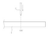
작은크기의 유리관(1a)을 얻기 위해서는 도 1 과 같이 길이가 긴 유리관(1)을 재단된 길이로 절단하여 원하는 작은 크기의 유리관(1a)을 얻게 되는 것이다.In order to obtain a small sized glass tube 1a, the
도 2 는 절단된 유리관(1a)을 나타낸다.2 shows a cut glass tube 1a.
도 2 와 같은 절단된 유리관(1a)을 얻기위한 종래의 방법은 도 3 에 도시된 바와같이 디스크 형상의 다이아몬드 절단날(2)을 고속으로 회전시켜 유리관(1)의 절단부위를 컷팅하는 것이다.The conventional method for obtaining the cut glass tube 1a as shown in FIG. 2 is to cut the cut portion of the
그러나, 종래기술은 디스크 타입의 절단날(2)을 사용함에 따라 절단시 절단날의 두께만큼 유리소재가 손실되기 때문에 유리관(1)으로 부터 원하는 만큼의 절단된 유리관(1a)을 획득하지 못하게되는 문제점이 발생하고 있었다.However, in the prior art, since the glass material is lost by the thickness of the cutting blade when cutting using the disc
또한, 절단날(2)을 이용하여 유리관을 절단함에 따라 절단면이 매끄럽지 못하여 절단면을 후공정에서 다시 연마해야만 하는 등 제품의 생산성이 나빠지는 문제점이 발생하고 있었다.
In addition, as the glass tube is cut using the
따라서, 상기 문제점을 해결하기 위한 본 발명은 주축의 외주연에 유리관이 수직으로 끼워지는 유리관 이송공급부재를 설치하여 절단 대상이 되는 유리관이 연속적으로 로딩위치(A), 1차하강위치(B), 2차하강위치(C), 반칼컷팅위치(D), 아암리셋위치(E), 절단위치(F)로 공급되도록 하고, 반칼컷팅위치로 공급된 유리관을 레이저를 이용하여 반칼 컷팅한 후 절단위치에서 최종적으로 절단한 후 배출토록 구성하므로서, 유리관을 연속적으로 절단할 수 있고, 저출력 레이저를 이용해서도 유리관을 컷팅할 수 있으면서도 유리관 절단시 손실이 발생하지 않도록 한 수직형 유리관 레이저 절단장치를 제공함을 목적으로 한다.
Therefore, the present invention for solving the above problems by installing the glass tube feed supply member that is inserted into the glass tube vertically on the outer periphery of the main shaft, the glass tube to be cut continuously loading position (A), primary lowering position (B) To be supplied to the second lowered position (C), the half-cutting position (D), the arm reset position (E), and the cutting position (F), and the half-cutting of the glass tube supplied to the half-cutting position using a laser is cut. Provides a vertical glass tube laser cutting device that can cut the glass tube continuously and cut the glass tube even when using low-power laser, but not to lose the glass tube. For the purpose.
상기 목적달성을 위한 본 발명은In order to achieve the above object,
베이스(5)의 상부에 모터의 회전력에 의해 일방향으로 회전하도록 설치되고, 외주연에 다수의 수직축(7)이 환형으로 결합되는 주축(6)과;A
수직축(7)의 하단에 각각 결합되고, 유리관(1)이 수직방향으로 끼워져 결합될 수 있도록 유리관(1)의 하단을 잡아주는 고정아암(20)과 구동아암(21)을 구비하며, 회전하는 주축(6)에 의해 유리관(1)을 로딩위치(A), 1차하강위치(B), 2차하강위치(C), 반칼컷팅위치(D), 아암리셋위치(E), 절단위치(F)로 이송 공급하는 유리관 이송 공급부재(10)와;It is coupled to the lower end of the vertical axis (7), and has a
1차하강위치(B)와 2차하강위치(C)에 각각 설치되고 유리관 이송 공급부재(10)의 구동아암(21)을 작동시켜 유리관(1)을 잡고있던 구속력이 해제되도록 하여 유리관(1)을 하강시키는 아암작동부(30)와;Installed in the primary lowering position (B) and the secondary lowering position (C), respectively, by operating the
1차하강위치(B)와 2차하강위치(C)에 각각 설치되고, 하강하는 유리관(1)의 하측을 받쳐주어 유리관(1)에 충격이 가해지지 않도록 하면서 유리관(1)을 절단길이만큼 하강시키는 완충부재(40)와;It is installed at the primary lowering position (B) and the secondary lowering position (C), respectively, and supports the lower side of the descending
반칼컷팅위치(D)의 일측으로 설치되고, 회전하는 유리관(1)의 절단부위 측면부로 레이저를 조사하여 유리관 두께의 일부분만을 반칼컷팅하는 레이저건(3)과;A laser gun (3) installed at one side of the half-cutting position (D) and irradiating a laser to a side of the cut portion of the rotating glass tube (1) to half-cut the portion of the glass tube thickness;
반칼컷팅위치(D)의 일측으로 설치되고, 반칼컷팅동작시 유리관 이송공급부재(10)를 회전시켜 유리관(1)이 회전하도록 하는 회전부재(50)와;A rotating
아암리셋위치(E)에 설치되고, 유리관 이송공급부재(10)를 정밀하게 회전시켜 구동아암(21)을 초기위치로 리셋시켜 다음의 유리관하강동작시 아암작동부(30)가 구동아암(21)작동시킬 수 있도록 하는 리셋부재(60)와;It is installed in the arm reset position (E), the glass tube feed supply member (10) is precisely rotated to reset the drive arm (21) to the initial position, and the arm operating portion (30) moves the drive arm (21) during the next glass tube lowering operation. A reset member (60) to enable operation;
절단위치(F)에 설치되어 반칼컷팅된 유리관(1)을 잡고 일정각도 비틀어 절단시키는 집게로봇(70); 으로 구성한 것을 특징으로 한다.
A
본 발명에 의하면, 유리관을 연속적으로 절단할 수 있고, 저출력 레이저를 이용해서도 유리관을 컷팅할 수 있으면서도 유리관 절단시 손실이 발생하지 않도록할 수 있으며, 유리관 절단면이 매끄럽게 절단됨에 따라 절단면을 추가적으로 연마하지 않아도 되도록 하는 효과를 기대할 수 있다.
According to the present invention, the glass tube can be continuously cut, the glass tube can be cut using a low-power laser, but the loss can be prevented when the glass tube is cut, and as the glass tube cut surface is smoothly cut, the cutting surface is not further polished. You can expect the effect of not having to.
도 1 은 벌브용 유리관을 획득하는 상태를 보인 도면.
도 2 는 자동차용 벌브 생산을 위한 유리관을 보인 도면.
도 3 은 종래 유리관 절단방법을 설명하기 위한 도면.
도 4 는 본 발명의 유리관 레이저 절단장치를 보인 정면도.
도 5 는 본 발명의 유리관 레이저 절단장치를 보인 평면도.
도 6 은 본 발명에 적용된 유리관 이송 공급부재를 보인 단면도.
도 7 은 본 발명에 적용된 완충부재와 아암작동부재의 동작상태를 보인 도면.
도 8 은 본 발명에 적용된 회전부재의 작동상태를 보인 도면.
도 9 는 본 발명에 적용된 리셋부재의 작동상태를 보인 도면.
도 10 은 본 발명에서 레이저로 반칼컷팅된 유리관을 집게로봇이 절단하여 취출하는 상태를 보인 도면.1 is a view showing a state of obtaining a glass tube for a bulb.
Figure 2 shows a glass tube for bulb production for automobiles.
3 is a view for explaining a conventional glass tube cutting method.
Figure 4 is a front view showing a glass tube laser cutting device of the present invention.
5 is a plan view showing a glass tube laser cutting device of the present invention.
Figure 6 is a cross-sectional view showing a glass tube feed supply member applied to the present invention.
Figure 7 is a view showing the operating state of the buffer member and the arm operating member applied to the present invention.
8 is a view showing an operating state of the rotating member applied to the present invention.
9 is a view showing the operating state of the reset member applied to the present invention.
10 is a view showing a state in which the forceps robot cut out the glass tube half-cut with a laser in the present invention.
이하, 첨부된 도면 도 4 내지 도 10 을 참조하여 본 발명의 바람직한 실시예를 설명하면 다음과 같다.Hereinafter, preferred embodiments of the present invention will be described with reference to the accompanying drawings.
본 발명의 설명에 있어서 종래와 동일한 구성요소에 대해서는 동일부호 표기하여 중복설명을 피하기로 한다.In the description of the present invention, the same constituent elements as those in the conventional art are denoted by the same reference numerals, and redundant description will be avoided.
상기 도면에 의하면, 본 발명은,According to the above drawings,
베이스(5)의 상부에 모터의 회전력에 의해 일방향으로 회전하도록 설치되고, 외주연에 다수의 수직축(7)이 환형으로 결합되는 주축(6)과;A
수직축(7)의 하단에 각각 결합되고, 유리관(1)이 수직방향으로 끼워져 결합될 수 있도록 유리관(1)의 하단을 잡아주는 고정아암(20)과 구동아암(21)을 구비하며, 회전하는 주축(6)에 의해 유리관(1)을 로딩위치(A), 1차하강위치(B), 2차하강위치(C), 반칼컷팅위치(D), 아암리셋위치(E), 절단위치(F)로 이송 공급하는 유리관 이송 공급부재(10)와;It is coupled to the lower end of the vertical axis (7), and has a
1차하강위치(B)와 2차하강위치(C)에 각각 설치되고 유리관 이송 공급부재(10)의 구동아암(21)을 작동시켜 유리관(1)을 잡고있던 구속력이 해제되도록 하여 유리관(1)을 하강시키는 아암작동부(30)와;Installed in the primary lowering position (B) and the secondary lowering position (C), respectively, by operating the
1차하강위치(B)와 2차하강위치(C)에 각각 설치되고, 하강하는 유리관(1)의 하측을 받쳐주어 유리관(1)에 충격이 가해지지 않도록 하면서 유리관(1)을 절단길이만큼 하강시키는 완충부재(40)와;It is installed at the primary lowering position (B) and the secondary lowering position (C), respectively, and supports the lower side of the descending
반칼컷팅위치(D)의 일측으로 설치되고, 회전하는 유리관(1)의 절단부위 측면부로 레이저를 조사하여 유리관 두께의 일부분만을 반칼컷팅하는 레이저건(3)과;A laser gun (3) installed at one side of the half-cutting position (D) and irradiating a laser to a side of the cut portion of the rotating glass tube (1) to half-cut the portion of the glass tube thickness;
반칼컷팅위치(D)의 일측으로 설치되고, 반칼컷팅동작시 유리관 이송공급부재(10)를 회전시켜 유리관(1)이 회전하도록 하는 회전부재(50)와;A rotating
아암리셋위치(E)에 설치되고, 유리관 이송공급부재(10)를 정밀하게 회전시켜 구동아암(21)을 초기위치로 리셋시켜 다음의 유리관하강동작시 아암작동부(30)가 구동아암(21)작동시킬 수 있도록 하는 리셋부재(60)와;It is installed in the arm reset position (E), the glass tube feed supply member (10) is precisely rotated to reset the drive arm (21) to the initial position, and the arm operating portion (30) moves the drive arm (21) during the next glass tube lowering operation. A reset member (60) to enable operation;
절단위치(F)에 설치되어 반칼컷팅된 유리관(1)을 잡고 일정각도 비틀어 절단시키는 집게로봇(70); 으로 구성한 것을 특징으로 한다.A
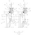
도 4 는 본 발명의 유리관 레이저 절단장치를 보인 정면도이고, 도 5 는 평면도이다.4 is a front view showing a glass tube laser cutting device of the present invention, Figure 5 is a plan view.
베이스(5)의 상부에 주축(6)이 수직방향으로 세워져 설치되고, 이 주축(6)의 외주연에는 다수의 수직축(7)이 결합되어 있다.The
주축(6)은 베이스(5) 내부에 설치된 미도시된 구동모터에 의해 일정 주기마다 일방향으로 회전하도록 구성된다.The
수직축(7)의 하단에는 유리관 이송공급부재(10)를 결합하기 위한 결합편(8)이 설치되어 있고, 수직축(7)에는 유리관 이송공급부재(10)에 수직방향으로 끼워지는 유리관(1)의 중간부와 상부가 거치되기 위한 'C'자 모양의 거치부(9)가 복수개 설치된다.The lower end of the vertical shaft (7) is provided with a coupling piece (8) for coupling the glass tube feed supply member (10), the vertical shaft (7) is a glass tube (1) fitted in the vertical direction to the glass tube feed supply member (10) A plurality of 'C'
상기 유리관 이송 공급부재(10)는 수직축(7)의 하단에 각각 결합되어 도 5 에 도시된 바와같이 주축(6)의 외주연에 환형으로 배치되며, 회전하는 주축(6)에 의해 유리관(1)을 유리관을 거치부(9)에 거치시켜 유리관 이송 공급부재(10)에 끼우는 로딩위치(A), 유리관(1)을 1차 하강시키는 1차하강위치(B), 유리관(1)을 절단길이만큼 하강시키는 2차하강위치(C), 레이저건(3)을 이용하여 유리관(1)을 반칼컷팅하는 유리관반칼컷팅위치(D), 반칼컷팅시 회전한 구동아암(21)을 초기위치로 리셋팅하는 아암리셋위치(E), 반칼컷팅된 유리관(1)을 절단하여 배출하는 절단위치(F)로 이송 공급한다.The glass tube
유리관 이송 공급부재(10)는 도 6 에 도시된 바와같이,Glass tube
수직축(7)의 하단에 설치된 결합편(8)에 내부가 비어있는 관 형태의 하우징(11) 외주연에 돌출된 결합날개(12)를 볼트로서 결합하고, 유리관(1)이 관통하는 중앙홀(15)이 구비되고 상부에 하우징(11)의 상측으로 노출되는 접촉부(14)가 구비된 회전체(13)를 하우징(11) 내측에 베어링(13a)으로 결합하며, 회전체(13)의 하측에 하부체(16)를 볼트(17)로서 결합하고, 하부체(16)의 하단에 서로 맞대어져 유리관(1)을 잡아주는 고정아암(20)과 구동아암(21)을 설치한다.A central hole through which the
이때, 상기 고정아암(20)은 2개 설치하고, 구동아암(21)은 1개 설치하는 것이 바람직하고, 2개의 고정아암(20)과 1개의 구동아암(21)은 서로 120도 간격으로 중심을 향해 설치한다.At this time, it is preferable that two fixed
구동아암(21)은 하측에 유리관(1)에 접촉되는 지지단(23)이 형성되고, 상측에 작동돌부(25)가 하부체(16) 외측으로 돌출되도록 형성된 아암몸체(22)를 구비하고, 아암몸체(22)의 하단을 하부체(16)의 하측에 힌지축(24)으로 축지하여 설치하고, 아암몸체(22)의 중간부와 하부체(16) 사이에 지지단(23)이 유리관(1)에 접촉하는 방향으로 탄성을 가하는 스프링(26)을 연결하여 구성한다.The
이에따라, 평상시에는 스프링(26)의 탄성에 의해 지지단(23)이 중심을 향하게되어 지지단(23)과 고정아암(20)이 유리관(1)을 잡아주게되는 것이고, 아암작동부(30)가 작동돌부(25)를 상측으로 밀어올릴때 지지단(23)이 외측으로 회전하면서 유리관(1)이 자체 하중에 의해 하강하게 된다.Accordingly, the
한편, 1차 하강위치(B)와 2차 하강위치(C)에 설치되는 아암작동부(30)는 베이스(5) 상부에 설치되는 지지대(31)의 상단에 출몰하여 구동아암(21)을 상측으로 밀어올려 지지단(23)이 유리관(1) 표면으로 부터 이탈되도록 하는 실린더(32)를 설치하여 구성한다.On the other hand, the
그리고, 완충부재(40)는 1차 하강위치(B)에 설치되는 제 1 완충부(41)와, 2차 하강위치(C)에 설치되는 제 2 완충부(47)로 구성하되,And, the
제 1 완충부(41)는 베이스(5)의 상부에 설치되는 설치대(42)와, 설치대(42)의 일측으로 설치되고 상하로 출몰하는 작동간(44)을 구비한 제 1 실린더(43)와, 상기 작동간(44)의 상부에 설치되고 상승하였다가 하강하면서 유리관 이송 공급부재(10)로 부터 하강하는 유리관(1)의 하단을 받쳐주어 1차 하강거리만큼 하강시키는 완충봉(46)을 구비한 제 2 실린더(45)로 구성하고,The first
제 2 완충부(47)는 베이스(5)의 상부에 설치되는 설치대(42a)와, 설치대(42a)의 일측으로 설치되고 상하로 출몰하는 작동간(44a)을 구비한 제 1 실린더(43a)와, 상기 작동간(44a)의 상부에 설치되고 상승하였다가 하강하면서 유리관 이송 공급부재(10)로 부터 2차 하강하는 유리관(1)의 하단을 받쳐주어 절단길이만큼 하강시키는 완충봉(46a)을 구비한 제 2 실린더(45a)로 구성한다.The second
상기와 같이 제 1 완충부(41)와 제 2 완충부(47)를 이용하여 두번에 걸쳐 유리관(1)을 절단길이만큼 하강시키는 이유는 한번에 절단길이만큼 하강시킬 경우 하강거리가 길어지면서 큰 충격이 유리관(1)에 가해져 파손되는 현상을 방지하기 위함이다.The reason why the
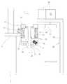
한편, 상기 회전부재(50)는 베이스(5)의 상부에 전후진 가능하게 설치되는 제 1 이송브라켓(51)과, 제 1 이송브라켓(51)의 상부에 설치되는 구동모터(52)와, 구동모터(52)의 축에 제 1 구동롤러(53)를 설치 구성하여, 제 1 이송브라켓(51)의 전진동작에 의해 반칼컷팅위치(D)에 위치한 유리관 이송공급부재(10)의 접촉부(14)에 제 1 구동롤러(53)가 접촉하면서 회전체(13)를 회전시켜 유리관(1)을 회전시킬 수 있도록 구성한다.On the other hand, the rotating
그리고, 상기 리셋부재(60)는 베이스(5)의 상부에 전후진 가능하게 설치되는 제 2 이송브라켓(61)과, 제 2 이송브라켓(61)의 중간부에 돌출되게 설치되고 유리관 이송공급부재(10)의 작동돌부(25)의 위치를 감지하는 감지부(64)와, 제 2 이송브라켓(61)의 상부에 설치되고 유리관 이송공급부재(10)의 접촉부(14)에 접촉되는 제 2 구동롤러(63)가 회전축에 설치되며, 감지부(64)에서 작동돌부(25)가 감지될때까지 제 2 구동롤러(63)를 회전시켰다가 정지하는 서보모터(62)로 구성한다.In addition, the
상기 제 1 이송브라켓(51)과 제 2 이송브라켓(61)은 미도시된 실린더 또는 모터의 작동으로 전진 또는 후진하도록 구성한다.The
상기 감지부(64)는 근접센서를 이용하여 작동돌부(25)가 근접한 것을 감지하거나, 작동돌부(25)의 끝단에 자석을 내장시키고 감지부(64)를 자석의 자력을 감지하는 홀센서로 구성하여 작동돌부(25)가 감지부(64)에 근접한 상태를 감지할 수 있도록 하는 것이 바람직하다.The
그리고, 서보모터(62)는 미도시된 제어장치의 제어에 의해 정밀제어되며, 제어장치의 제어에 의해 제 2 이송브라켓(61)과 서보모터(62)가 동작하여 제 2 구동롤러(63)가 접촉부(14)에 접촉하면서 회전체(13)가 서서히 회전하게되고, 이 회전에 의해 작동돌부(25)가 감지부(64)에 의해 감지되면 제어장치가 서보모터(62)를 정지시켜 작동돌부(25)가 초기위치(아암작동부가 작동돌부(25)를 밀어올릴 수 있는 위치)로 리셋되는 것이다.And, the
상기 리셋부재(60)를 이용하여 작동돌부(25)를 초기위치로 리셋시키는 이유는 반칼컷팅위치(D)에서 회전부재(50)에 의해 유리관 이송공급부재(10)의 회전체(13)가 고속으로 회전하면서 유리관(1)이 반칼컷팅됨에 따라 작동돌부(25)의 위치가 초기위치를 벗어나기 때문이다.The reason for resetting the
이와같이 구성된 본 발명의 동작을 설명하면 다음과 같다.Referring to the operation of the present invention configured as described above is as follows.
◆ 로딩공정 ◆◆ Loading process ◆
로딩공정은 유리관(1)을 수직으로 세워 유리관 이송 공급부재(10)의 중앙홀(15)로 끼워 고정아암(20)과 구동아암(21)에 의해 파지되도록 하는 것이다.The loading process is to hold the glass tube (1) vertically to be gripped by the fixed arm (20) and the driving arm (21) by inserting it into the central hole (15) of the glass tube transfer supply member (10).
로딩공정은 유리관 이송 공급부재(10)가 로딩위치(A)에 존재할 때 작업자가 수작업으로 수행할 수 있고, 별도의 로봇을 이용하여 자동으로 공급할 수 있다.The loading process can be performed manually by the operator when the glass tube
◆ 1차 하강 공정 ◆◆ 1st descent process ◆
1차 하강 공정은 유리관(1)이 끼워진 유리관 이송 공급부재(10)가 1차 하강위치(B)에 도달하였을 때 이루어진다. The primary lowering step is performed when the glass tube
1차 하강 위치(B)에는 아암작동부(30)와 제 1 완충부(41)가 설치되어 있다.The
미도시된 제어장치의 제어에 따라 아암작동부(30)의 실린더(32)가 작동하여 작동간(33)이 상승하면서 작동돌부(25)를 밀어 올림에 따라 구동아암(21)이 벌어지면서 잡고있던 유리관(1)을 놓아주게 되므로 유리관(1)이 자체 하중에 의해 하강할 수 있게되며, 이때 제 1 완충부(41)의 제 1 실린더(43)와 제 2 실린더(45)가 작동간(44)과 완충봉(46)을 상승시켰다가 제 2 실린더(45)가 하강하는 유리관(1)의 하강 타이밍에 맞춰 완충봉(46)을 하강시키므로서, 자체 하중에 의해 하강하는 유리관(1)이 완충봉(46)에 받쳐진 상태로 큰 충격을 받지 않고 1차 하강하게 된다.The
◆ 2차 하강 공정 ◆◆ 2nd descent process ◆
2차 하강 공정은 1차 하강위치(B)에서 절단길이의 절반 정도 유리관(1)이 하강한 상태의 유리관 이송 공급부재(10)가 2차 하강위치(C)에 도달하였을 때 이루어진다. The secondary lowering process is performed when the glass tube
2차 하강 위치(C)에는 아암작동부(30)와 제 2 완충부(47)가 설치되어 있다.The
미도시된 제어장치의 제어에 따라 아암작동부(30)의 실린더(32)가 작동하여 작동간(33)이 상승하면서 작동돌부(25)를 밀어 올림에 따라 구동아암(21)이 벌어지면서 잡고있던 유리관(1)을 놓아주게 되므로 유리관(1)이 자체 하중에 의해 하강할 수 있게되며, 이때 제 2 완충부(47)의 제 1 실린더(43a)는 작동하지 않고 제 2 실린더(45a)가 완충봉(46a)을 상승시켰다가 제 2 실린더(45a)가 하강하는 유리관(1)의 하강 타이밍에 맞춰 완충봉(46a)을 하강시키므로서, 자체 하중에 의해 하강하는 유리관(1)이 완충봉(46a)에 받쳐진 상태로 큰 충격을 받지 않고 절달길이만큼 하강하게 된다.The
◆ 반칼 컷팅공정 ◆◆ half knife cutting process ◆
반칼 컷팅공정은 유리관 이송 공급부재(10)로 부터 하측으로 절단길이만큼 하강한 유리관(1)을 레이저를 이용하여 반칼 컷팅하는 공정이며, 유리관 이송 공급부재(10)가 반칼 컷팅위치(D)에 도달하였을때 이루어진다.The half knife cutting process is a process of half-cutting the
반칼 컷팅위치(D)에는 유리관(1)을 회전시키기 위한 회전부재(50)가 설치되어 있고, 또한 레이저를 유리관(1)의 측면으로 조사하기 위한 레이저건(3)이 설치되어 있다.The rotating
미도시된 제어장치의 제어에 따라 제 1 이송브라켓(51)이 전진함과 동시에 구동모터(52)가 구동함에 따라 제 1 구동롤러(53)가 유리관 이송 공급부재(10)의 접촉부(14)에 접촉됨에 따라 회전체(13)가 고속으로 회전하게되고, 이에의해 유리관(1)이 회전하게 된다.As the
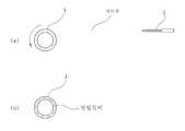
이때, 유리관(1)의 측면에 위치하고 있는 레이저건(3)에서 레이저가 조사됨에 따라 도 11에 도시된 바와같이 레이저가 유리관(1)의 전체 두께에 대해 절반정도를 컷팅하게 되며, 레이저 조사 후 설정된 시간이 경과하면 미도시된 제어장치는 구동모터(52)를 정지시킴과 동시에 레이저건(3)을 오프시킨다.At this time, as the laser is irradiated from the
반칼컷팅공정에서 유리관 이송 공급부재(10)의 회전체(13)가 고속으로 회전함에 따라 구동아암(21)의 작동돌부(25)가 초기 위치가 아닌 다른 위치에 존재하게 된다.As the
◆ 아암 리셋공정 ◆◆ Arm reset process ◆
아암 리셋공정은 반칼 컷팅공정에서 초기위치로 부터 벗어난 작동돌부(25)를 초기위치로 리셋하는 공정이다.The arm reset process is a process of resetting the
아암 리셋위치(E)에는 리셋부재(60)가 설치된다.In the arm reset position E, a
미도시된 제어장치의 제어에 의해 제 2 이송브라켓(61)과 서보모터(62)가 동작하여 제 2 구동롤러(63)가 접촉부(14)에 접촉하면서 회전체(13)가 서서히 회전하게되고, 이 회전에 의해 작동돌부(25)가 감지부(64)에 의해 감지되면 제어장치가 서보모터(62)를 정지시킴에 따라 작동돌부(25)가 초기위치(아암작동부가 작동돌부(25)를 밀어올릴 수 있는 위치)로 리셋되는 것이다.The second conveying
◆ 절단공정 ◆◆ Cutting Process ◆
절단공정은 반칼컷팅공정에서 레이저에 의해 반칼컷팅된 유리관(1)을 완전히 절단하여 배출시키는 공정이다.The cutting process is a process of completely cutting and discharging the
절단위치(F)에는 유리관(1)을 잡고 비틀어 절단시키는 집게로봇(70)이 설치되며, 또한 집게로봇(70)이 절단된 유리관(1)을 외부로 배출시킬 수 있는 배출컨베이어가 설치된다.
At the cutting position F, the
상기 설명된 일련의 공정은 주축(6)에 의해 다수의 유리관 이송 공급부재(10)가 동시 다발적으로 유리관(1)을 이송시키므로서, 유리관 레이저 반칼컷팅동작이 연속적으로 이루어질 수 있게되는 것이다.
The series of processes described above is such that the glass tube laser semi-cutting operation can be continuously performed by the plurality of glass tube
1: 유리관, 3: 레이저건,
5: 베이스, 6: 주축,
7: 수직축, 8: 결합편,
9: 거치부,10: 유리관 이송 공급부재,
11: 하우징, 12: 결합날개,
13: 회전체, 14: 접촉부,
15: 중앙홀,16: 하부체,
20: 고정암,21: 구동아암,
30: 아암작동부,40: 완충부재,
50: 회전부재, 60: 리셋부재,
70: 집게로봇,1: glass tube, 3: laser gun,
5: base, 6: spindle,
7: vertical axis, 8: engagement piece,
9: mounting part, 10: glass tube feeding and feeding member,
11: housing, 12: coupling wing,
13: rotating body, 14: contact portion,
15: concourse, 16: lower body,
20: fixed arm, 21: driving arm,
30: arm operating portion, 40: buffer member,
50: rotation member, 60: reset member,
70: tongs robot,
Claims (4)
Translated fromKorean수직축(7)의 하단에 각각 결합되고, 유리관(1)이 수직방향으로 끼워져 결합될 수 있도록 유리관(1)의 하단을 잡아주는 고정아암(20)과 구동아암(21)을 구비하며, 회전하는 주축(6)에 의해 유리관(1)을 로딩위치(A), 1차하강위치(B), 2차하강위치(C), 반칼컷팅위치(D), 아암리셋위치(E), 절단위치(F)로 이송 공급하는 유리관 이송 공급부재(10)와;
1차하강위치(B)와 2차하강위치(C)에 각각 설치되고 유리관 이송 공급부재(10)의 구동아암(21)을 작동시켜 유리관(1)을 잡고있던 구속력이 해제되도록 하여 유리관(1)을 하강시키는 아암작동부(30)와;
1차하강위치(B)와 2차하강위치(C)에 각각 설치되고, 하강하는 유리관(1)의 하측을 받쳐주어 유리관(1)에 충격이 가해지지 않도록 하면서 유리관(1)을 절단길이만큼 하강시키는 완충부재(40)와;
반칼컷팅위치(D)의 일측으로 설치되고, 회전하는 유리관(1)의 절단부위 측면부로 레이저를 조사하여 유리관 두께의 일부분만을 반칼컷팅하는 레이저건(3)과;
반칼컷팅위치(D)의 일측으로 설치되고, 반칼컷팅동작시 유리관 이송공급부재(10)를 회전시켜 유리관(1)이 회전하도록 하는 회전부재(50)와;
아암리셋위치(E)에 설치되고, 유리관 이송공급부재(10)를 정밀하게 회전시켜 구동아암(21)을 초기위치로 리셋시켜 다음의 유리관하강동작시 아암작동부(30)가 구동아암(21)작동시킬 수 있도록 하는 리셋부재(60)와;
절단위치(F)에 설치되어 반칼컷팅된 유리관(1)을 잡고 일정각도 비틀어 절단시키는 집게로봇(70); 으로 구성한 것을 특징으로 하는 수직형 유리관 레이저 절단장치.
A main shaft 6 installed above the base 5 so as to rotate in one direction by a rotational force of the motor, and a plurality of vertical shafts 7 annularly coupled to the outer circumference;
It is coupled to the lower end of the vertical axis (7), and has a fixed arm 20 and the driving arm (21) for holding the lower end of the glass tube (1) so that the glass tube (1) is fitted in the vertical direction can be coupled, The glass tube 1 is loaded by the spindle 6 into the loading position (A), the primary lowering position (B), the secondary lowering position (C), the semi-cutting position (D), the arm reset position (E), and the cutting position ( A glass tube conveyance supply member (10) for conveyance and supply to F);
Installed in the primary lowering position (B) and the secondary lowering position (C), respectively, by operating the driving arm 21 of the glass tube feed supply member 10 to release the restraining force holding the glass tube (1) to the glass tube (1). An arm operating unit 30 for lowering);
It is installed at the primary lowering position (B) and the secondary lowering position (C), respectively, and supports the lower side of the descending glass tube 1 so that the glass tube 1 is cut to the cutting length while preventing the impact on the glass tube 1. A lowering member 40 for lowering;
A laser gun (3) installed at one side of the half-cutting position (D) and irradiating a laser to a side of the cut portion of the rotating glass tube (1) to half-cut the portion of the glass tube thickness;
A rotating member 50 installed at one side of the half-cutting position D and rotating the glass tube feeding and feeding member 10 during the half-cutting operation so that the glass tube 1 rotates;
It is installed in the arm reset position (E), the glass tube feed supply member (10) is precisely rotated to reset the drive arm (21) to the initial position, and the arm operating portion (30) moves the drive arm (21) during the next glass tube lowering operation. A reset member (60) to enable operation;
A forceps robot 70 that is installed at the cutting position F and holds the semi-cut cut glass tube 1 and twists it by a predetermined angle; Vertical glass tube laser cutting device comprising a.
상기 유리관 이송 공급부재(10)는 수직축(7)의 하단에 내부가 비어있는 관 형태의 하우징(11)을 결합하고, 유리관(1)이 관통하는 중앙홀(15)이 구비되고 상부에 하우징(11)의 상측으로 노출되는 접촉부(14)가 구비된 회전체(13)를 하우징(11) 내측에 베어링(13a)으로 결합하며, 회전체(13)의 하측에 하부체(16)를 볼트(17)로서 결합하고, 하부체(16)의 하단에 서로 맞대어져 유리관(1)을 잡아주는 고정아암(20)과 구동아암(21)을 설치하되,
구동아암(21)은 하측에 유리관(1)에 접촉되는 지지단(23)이 형성되고, 상측에 작동돌부(25)가 하부체(16) 외측으로 돌출되도록 형성된 아암몸체(22)를 구비하고, 아암몸체(22)의 하단을 하부체(16)의 하측에 힌지축(24)으로 축지하여 설치하고, 아암몸체(22)의 중간부와 하부체(16) 사이에 지지단(23)이 유리관(1)에 접촉하는 방향으로 탄성을 가하는 스프링(26)을 연결하여 구성한 것을 특징으로 하는 수직형 유리관 레이저 절단장치.
The method of claim 1,
The glass tube feed supply member 10 is coupled to the lower housing 11 of the vertical shaft (7) in the form of a hollow tube shape, the central hole 15 through which the glass tube 1 is provided and the housing ( The rotating body 13 having the contact portion 14 exposed to the upper side of the 11 is coupled to the inside of the housing 11 by a bearing 13a, and the lower body 16 is bolted to the lower side of the rotating body 13. 17) and the fixed arm 20 and the driving arm 21 to be fitted to each other at the lower end of the lower body 16 to hold the glass tube 1,
The driving arm 21 has a support end 23 in contact with the glass tube 1 on the lower side, and has an arm body 22 formed so that the operation protrusion 25 protrudes outward from the lower body 16 on the upper side. The lower end of the arm body 22 is axially installed on the lower side of the lower body 16 by a hinge shaft 24, and a support end 23 is provided between the middle part of the arm body 22 and the lower body 16. Vertical glass tube laser cutting device, characterized in that configured by connecting the spring 26 to apply elasticity in the direction in contact with the glass tube (1).
상기 아암작동부(30)는 베이스(5) 상부에 설치되는 지지대(31)의 상단에 출몰하여 구동아암(21)을 상측으로 밀어올려 지지단(23)이 유리관(1) 표면으로 부터 이탈되도록 하는 실린더(32)를 설치하여 구성하고,
완충부재(40)는 1차 하강위치(B)에 설치되는 제 1 완충부(41)와, 2차 하강위치(C)에 설치되는 제 2 완충부(47)로 구성하되,
제 1 완충부(41)와 제 2 완충부(47)는 베이스(5)의 상부에 설치되는 설치대(42)(42a)와, 설치대(42)(42a)의 일측으로 설치되고 상하로 출몰하는 작동간(44)(44a)을 구비한 제 1 실린더(43)(43a)와, 상기 작동간(44)(44a)의 상부에 설치되고 상승하였다가 하강하면서 유리관 이송 공급부재(10)로 부터 하강하는 유리관(1)의 하단을 받쳐주어 절단길이만큼 하강시키는 완충봉(46)(46a)을 구비한 제 2 실린더(45)(45a)로 구성한 것을 특징으로 하는 수직형 유리관 레이저 절단장치.
According to claim 1,
The arm operating portion 30 is raised to the upper end of the support 31 is installed on the base (5) to push the drive arm 21 upwards so that the support end 23 is separated from the surface of the glass tube (1) Install and configure the cylinder 32
The shock absorbing member 40 is composed of a first shock absorbing portion 41 installed in the primary lowering position (B) and a second shock absorbing portion 47 installed in the secondary lowering position (C),
The first shock absorbing portion 41 and the second shock absorbing portion 47 are installed on one side of the mounting table 42 and 42a and the mounting table 42 and 42a which are installed on the upper portion of the base 5, The first cylinder 43 (43a) having the operating intervals 44 and 44a, and from the glass tube feed supply member 10 while being installed on the upper portion of the operation intervals 44 and 44a and being raised and lowered. A vertical glass tube laser cutting device comprising: a second cylinder (45) (45a) having a buffer rod (46) (46a) supporting the lower end of the glass tube (1) to be lowered and being lowered by the cutting length.
상기 회전부재(50)는 베이스(5)의 상부에 전후진 가능하게 설치되는 제 1 이송브라켓(51)과, 제 1 이송브라켓(51)의 상부에 설치되는 구동모터(52)와, 구동모터(52)의 축에 제 1 구동롤러(53)를 설치 구성하여, 제 1 이송브라켓(51)의 전진동작에 의해 반칼컷팅위치(D)에 위치한 유리관 이송공급부재(10)의 접촉부(14)에 제 1 구동롤러(53)가 접촉하면서 회전체(13)를 회전시켜 유리관(1)을 회전시킬 수 있도록 구성하고,
상기 리셋부재(60)는 베이스(5)의 상부에 전후진 가능하게 설치되는 제 2 이송브라켓(61)과, 제 2 이송브라켓(61)의 중간부에 돌출되게 설치되고 유리관 이송공급부재(10)의 작동돌부(25)의 위치를 감지하는 감지부(64)와, 제 2 이송브라켓(61)의 상부에 설치되고 유리관 이송공급부재(10)의 접촉부(14)에 접촉되는 제 2 구동롤러(63)가 회전축에 설치되며, 감지부(64)에서 작동돌부(25)가 감지될때까지 제 2 구동롤러(63)를 회전시켰다가 정지하는 서보모터(62)로 구성한 것을 특징으로 하는 수직형 유리관 레이저 절단장치.According to claim 1,
The rotating member 50 includes a first transfer bracket 51 installed on the upper portion of the base 5 so as to be movable forward and backward, a drive motor 52 installed on the upper portion of the first transfer bracket 51, and a drive motor. The first driving roller 53 is installed and configured on the shaft of 52 so that the contact portion 14 of the glass tube feed supply member 10 positioned at the semi-cutting position D by the forward movement of the first transfer bracket 51. It is configured to rotate the glass tube 1 by rotating the rotary body 13 while the first drive roller 53 is in contact with,
The reset member 60 is installed on the upper portion of the base 5 so as to protrude forward and backward, and is installed to protrude from the middle portion of the second transfer bracket 61 and the glass tube feed supply member 10. The second drive roller is installed on the sensing unit 64 for detecting the position of the operation protrusion 25 of the c) and the second conveying bracket 61 and in contact with the contact portion 14 of the glass tube feed supply member 10. (63) is installed on the rotating shaft, the vertical type, characterized in that consisting of a servo motor 62 for rotating and stopping the second drive roller 63 until the operating projection 25 is detected by the detection unit 64 Glass tube laser cutting device.
Priority Applications (1)
| Application Number | Priority Date | Filing Date | Title |
|---|---|---|---|
| KR1020130079391AKR101344368B1 (en) | 2013-07-08 | 2013-07-08 | Cutting device for glass tube using laser |
Applications Claiming Priority (1)
| Application Number | Priority Date | Filing Date | Title |
|---|---|---|---|
| KR1020130079391AKR101344368B1 (en) | 2013-07-08 | 2013-07-08 | Cutting device for glass tube using laser |
Publications (1)
| Publication Number | Publication Date |
|---|---|
| KR101344368B1true KR101344368B1 (en) | 2013-12-24 |
Family
ID=49988989
Family Applications (1)
| Application Number | Title | Priority Date | Filing Date |
|---|---|---|---|
| KR1020130079391AExpired - Fee RelatedKR101344368B1 (en) | 2013-07-08 | 2013-07-08 | Cutting device for glass tube using laser |
Country Status (1)
| Country | Link |
|---|---|
| KR (1) | KR101344368B1 (en) |
Cited By (38)
| Publication number | Priority date | Publication date | Assignee | Title |
|---|---|---|---|---|
| US20150140241A1 (en)* | 2013-11-19 | 2015-05-21 | Rofin-Sinar Technologies Inc. | Method and apparatus for spiral cutting a glass tube using filamentation by burst ultrafast laser pulses |
| US9676167B2 (en) | 2013-12-17 | 2017-06-13 | Corning Incorporated | Laser processing of sapphire substrate and related applications |
| US9701564B2 (en) | 2013-01-15 | 2017-07-11 | Corning Incorporated | Systems and methods of glass cutting by inducing pulsed laser perforations into glass articles |
| US9701563B2 (en) | 2013-12-17 | 2017-07-11 | Corning Incorporated | Laser cut composite glass article and method of cutting |
| US9815730B2 (en) | 2013-12-17 | 2017-11-14 | Corning Incorporated | Processing 3D shaped transparent brittle substrate |
| US9815144B2 (en) | 2014-07-08 | 2017-11-14 | Corning Incorporated | Methods and apparatuses for laser processing materials |
| US9850160B2 (en) | 2013-12-17 | 2017-12-26 | Corning Incorporated | Laser cutting of display glass compositions |
| US9850159B2 (en) | 2012-11-20 | 2017-12-26 | Corning Incorporated | High speed laser processing of transparent materials |
| US10047001B2 (en) | 2014-12-04 | 2018-08-14 | Corning Incorporated | Glass cutting systems and methods using non-diffracting laser beams |
| US10144093B2 (en) | 2013-12-17 | 2018-12-04 | Corning Incorporated | Method for rapid laser drilling of holes in glass and products made therefrom |
| US10173916B2 (en) | 2013-12-17 | 2019-01-08 | Corning Incorporated | Edge chamfering by mechanically processing laser cut glass |
| US10233112B2 (en) | 2013-12-17 | 2019-03-19 | Corning Incorporated | Laser processing of slots and holes |
| US10252931B2 (en) | 2015-01-12 | 2019-04-09 | Corning Incorporated | Laser cutting of thermally tempered substrates |
| US10280108B2 (en) | 2013-03-21 | 2019-05-07 | Corning Laser Technologies GmbH | Device and method for cutting out contours from planar substrates by means of laser |
| US10335902B2 (en) | 2014-07-14 | 2019-07-02 | Corning Incorporated | Method and system for arresting crack propagation |
| US10377658B2 (en) | 2016-07-29 | 2019-08-13 | Corning Incorporated | Apparatuses and methods for laser processing |
| US10421683B2 (en) | 2013-01-15 | 2019-09-24 | Corning Laser Technologies GmbH | Method and device for the laser-based machining of sheet-like substrates |
| US10522963B2 (en) | 2016-08-30 | 2019-12-31 | Corning Incorporated | Laser cutting of materials with intensity mapping optical system |
| US10525657B2 (en) | 2015-03-27 | 2020-01-07 | Corning Incorporated | Gas permeable window and method of fabricating the same |
| US10526234B2 (en) | 2014-07-14 | 2020-01-07 | Corning Incorporated | Interface block; system for and method of cutting a substrate being transparent within a range of wavelengths using such interface block |
| US10611667B2 (en) | 2014-07-14 | 2020-04-07 | Corning Incorporated | Method and system for forming perforations |
| US10626040B2 (en) | 2017-06-15 | 2020-04-21 | Corning Incorporated | Articles capable of individual singulation |
| US10688599B2 (en) | 2017-02-09 | 2020-06-23 | Corning Incorporated | Apparatus and methods for laser processing transparent workpieces using phase shifted focal lines |
| US10730783B2 (en) | 2016-09-30 | 2020-08-04 | Corning Incorporated | Apparatuses and methods for laser processing transparent workpieces using non-axisymmetric beam spots |
| US10752534B2 (en) | 2016-11-01 | 2020-08-25 | Corning Incorporated | Apparatuses and methods for laser processing laminate workpiece stacks |
| US11062986B2 (en) | 2017-05-25 | 2021-07-13 | Corning Incorporated | Articles having vias with geometry attributes and methods for fabricating the same |
| US11078112B2 (en) | 2017-05-25 | 2021-08-03 | Corning Incorporated | Silica-containing substrates with vias having an axially variable sidewall taper and methods for forming the same |
| US11111170B2 (en) | 2016-05-06 | 2021-09-07 | Corning Incorporated | Laser cutting and removal of contoured shapes from transparent substrates |
| US11114309B2 (en) | 2016-06-01 | 2021-09-07 | Corning Incorporated | Articles and methods of forming vias in substrates |
| US11186060B2 (en) | 2015-07-10 | 2021-11-30 | Corning Incorporated | Methods of continuous fabrication of holes in flexible substrate sheets and products relating to the same |
| US11542190B2 (en) | 2016-10-24 | 2023-01-03 | Corning Incorporated | Substrate processing station for laser-based machining of sheet-like glass substrates |
| US11554984B2 (en) | 2018-02-22 | 2023-01-17 | Corning Incorporated | Alkali-free borosilicate glasses with low post-HF etch roughness |
| US11648623B2 (en) | 2014-07-14 | 2023-05-16 | Corning Incorporated | Systems and methods for processing transparent materials using adjustable laser beam focal lines |
| US11774233B2 (en) | 2016-06-29 | 2023-10-03 | Corning Incorporated | Method and system for measuring geometric parameters of through holes |
| US11773004B2 (en) | 2015-03-24 | 2023-10-03 | Corning Incorporated | Laser cutting and processing of display glass compositions |
| CN117300386A (en)* | 2023-11-28 | 2023-12-29 | 山东明驰环境科技有限公司 | Laser cutting machine for glass fiber reinforced plastic pipe |
| CN118237773A (en)* | 2024-05-29 | 2024-06-25 | 四川岷河管道建设工程有限公司 | Tubular product production laser cutting equipment |
| US12180108B2 (en) | 2017-12-19 | 2024-12-31 | Corning Incorporated | Methods for etching vias in glass-based articles employing positive charge organic molecules |
Citations (3)
| Publication number | Priority date | Publication date | Assignee | Title |
|---|---|---|---|---|
| JP2000247661A (en) | 1999-02-23 | 2000-09-12 | Shin Etsu Chem Co Ltd | Fusing method and apparatus for fusing quartz glass base material and preform |
| JP2003048736A (en) | 2001-08-01 | 2003-02-21 | Nippon Electric Glass Co Ltd | Glass tube chucking device |
| JP2012025594A (en) | 2010-07-20 | 2012-02-09 | Sumitomo Electric Ind Ltd | Method for cutting glass base material and method for manufacturing glass base material |
- 2013
- 2013-07-08KRKR1020130079391Apatent/KR101344368B1/ennot_activeExpired - Fee Related
Patent Citations (3)
| Publication number | Priority date | Publication date | Assignee | Title |
|---|---|---|---|---|
| JP2000247661A (en) | 1999-02-23 | 2000-09-12 | Shin Etsu Chem Co Ltd | Fusing method and apparatus for fusing quartz glass base material and preform |
| JP2003048736A (en) | 2001-08-01 | 2003-02-21 | Nippon Electric Glass Co Ltd | Glass tube chucking device |
| JP2012025594A (en) | 2010-07-20 | 2012-02-09 | Sumitomo Electric Ind Ltd | Method for cutting glass base material and method for manufacturing glass base material |
Cited By (55)
| Publication number | Priority date | Publication date | Assignee | Title |
|---|---|---|---|---|
| US9850159B2 (en) | 2012-11-20 | 2017-12-26 | Corning Incorporated | High speed laser processing of transparent materials |
| US9701564B2 (en) | 2013-01-15 | 2017-07-11 | Corning Incorporated | Systems and methods of glass cutting by inducing pulsed laser perforations into glass articles |
| US11028003B2 (en) | 2013-01-15 | 2021-06-08 | Corning Laser Technologies GmbH | Method and device for laser-based machining of flat substrates |
| US10421683B2 (en) | 2013-01-15 | 2019-09-24 | Corning Laser Technologies GmbH | Method and device for the laser-based machining of sheet-like substrates |
| US11345625B2 (en) | 2013-01-15 | 2022-05-31 | Corning Laser Technologies GmbH | Method and device for the laser-based machining of sheet-like substrates |
| US11713271B2 (en) | 2013-03-21 | 2023-08-01 | Corning Laser Technologies GmbH | Device and method for cutting out contours from planar substrates by means of laser |
| US10280108B2 (en) | 2013-03-21 | 2019-05-07 | Corning Laser Technologies GmbH | Device and method for cutting out contours from planar substrates by means of laser |
| US20150140241A1 (en)* | 2013-11-19 | 2015-05-21 | Rofin-Sinar Technologies Inc. | Method and apparatus for spiral cutting a glass tube using filamentation by burst ultrafast laser pulses |
| US10005152B2 (en)* | 2013-11-19 | 2018-06-26 | Rofin-Sinar Technologies Llc | Method and apparatus for spiral cutting a glass tube using filamentation by burst ultrafast laser pulses |
| US9850160B2 (en) | 2013-12-17 | 2017-12-26 | Corning Incorporated | Laser cutting of display glass compositions |
| US10442719B2 (en) | 2013-12-17 | 2019-10-15 | Corning Incorporated | Edge chamfering methods |
| US10173916B2 (en) | 2013-12-17 | 2019-01-08 | Corning Incorporated | Edge chamfering by mechanically processing laser cut glass |
| US10179748B2 (en) | 2013-12-17 | 2019-01-15 | Corning Incorporated | Laser processing of sapphire substrate and related applications |
| US10183885B2 (en) | 2013-12-17 | 2019-01-22 | Corning Incorporated | Laser cut composite glass article and method of cutting |
| US10233112B2 (en) | 2013-12-17 | 2019-03-19 | Corning Incorporated | Laser processing of slots and holes |
| US9676167B2 (en) | 2013-12-17 | 2017-06-13 | Corning Incorporated | Laser processing of sapphire substrate and related applications |
| US10597321B2 (en) | 2013-12-17 | 2020-03-24 | Corning Incorporated | Edge chamfering methods |
| US10293436B2 (en) | 2013-12-17 | 2019-05-21 | Corning Incorporated | Method for rapid laser drilling of holes in glass and products made therefrom |
| US10611668B2 (en) | 2013-12-17 | 2020-04-07 | Corning Incorporated | Laser cut composite glass article and method of cutting |
| US11148225B2 (en) | 2013-12-17 | 2021-10-19 | Corning Incorporated | Method for rapid laser drilling of holes in glass and products made therefrom |
| US10392290B2 (en) | 2013-12-17 | 2019-08-27 | Corning Incorporated | Processing 3D shaped transparent brittle substrate |
| US9815730B2 (en) | 2013-12-17 | 2017-11-14 | Corning Incorporated | Processing 3D shaped transparent brittle substrate |
| US10144093B2 (en) | 2013-12-17 | 2018-12-04 | Corning Incorporated | Method for rapid laser drilling of holes in glass and products made therefrom |
| US9701563B2 (en) | 2013-12-17 | 2017-07-11 | Corning Incorporated | Laser cut composite glass article and method of cutting |
| US9815144B2 (en) | 2014-07-08 | 2017-11-14 | Corning Incorporated | Methods and apparatuses for laser processing materials |
| US11697178B2 (en) | 2014-07-08 | 2023-07-11 | Corning Incorporated | Methods and apparatuses for laser processing materials |
| US10526234B2 (en) | 2014-07-14 | 2020-01-07 | Corning Incorporated | Interface block; system for and method of cutting a substrate being transparent within a range of wavelengths using such interface block |
| US10611667B2 (en) | 2014-07-14 | 2020-04-07 | Corning Incorporated | Method and system for forming perforations |
| US11648623B2 (en) | 2014-07-14 | 2023-05-16 | Corning Incorporated | Systems and methods for processing transparent materials using adjustable laser beam focal lines |
| US10335902B2 (en) | 2014-07-14 | 2019-07-02 | Corning Incorporated | Method and system for arresting crack propagation |
| US10047001B2 (en) | 2014-12-04 | 2018-08-14 | Corning Incorporated | Glass cutting systems and methods using non-diffracting laser beams |
| US11014845B2 (en) | 2014-12-04 | 2021-05-25 | Corning Incorporated | Method of laser cutting glass using non-diffracting laser beams |
| US10252931B2 (en) | 2015-01-12 | 2019-04-09 | Corning Incorporated | Laser cutting of thermally tempered substrates |
| US11773004B2 (en) | 2015-03-24 | 2023-10-03 | Corning Incorporated | Laser cutting and processing of display glass compositions |
| US10525657B2 (en) | 2015-03-27 | 2020-01-07 | Corning Incorporated | Gas permeable window and method of fabricating the same |
| US11186060B2 (en) | 2015-07-10 | 2021-11-30 | Corning Incorporated | Methods of continuous fabrication of holes in flexible substrate sheets and products relating to the same |
| US11111170B2 (en) | 2016-05-06 | 2021-09-07 | Corning Incorporated | Laser cutting and removal of contoured shapes from transparent substrates |
| US11114309B2 (en) | 2016-06-01 | 2021-09-07 | Corning Incorporated | Articles and methods of forming vias in substrates |
| US11774233B2 (en) | 2016-06-29 | 2023-10-03 | Corning Incorporated | Method and system for measuring geometric parameters of through holes |
| US10377658B2 (en) | 2016-07-29 | 2019-08-13 | Corning Incorporated | Apparatuses and methods for laser processing |
| US10522963B2 (en) | 2016-08-30 | 2019-12-31 | Corning Incorporated | Laser cutting of materials with intensity mapping optical system |
| US11130701B2 (en) | 2016-09-30 | 2021-09-28 | Corning Incorporated | Apparatuses and methods for laser processing transparent workpieces using non-axisymmetric beam spots |
| US10730783B2 (en) | 2016-09-30 | 2020-08-04 | Corning Incorporated | Apparatuses and methods for laser processing transparent workpieces using non-axisymmetric beam spots |
| US11542190B2 (en) | 2016-10-24 | 2023-01-03 | Corning Incorporated | Substrate processing station for laser-based machining of sheet-like glass substrates |
| US10752534B2 (en) | 2016-11-01 | 2020-08-25 | Corning Incorporated | Apparatuses and methods for laser processing laminate workpiece stacks |
| US10688599B2 (en) | 2017-02-09 | 2020-06-23 | Corning Incorporated | Apparatus and methods for laser processing transparent workpieces using phase shifted focal lines |
| US11062986B2 (en) | 2017-05-25 | 2021-07-13 | Corning Incorporated | Articles having vias with geometry attributes and methods for fabricating the same |
| US11078112B2 (en) | 2017-05-25 | 2021-08-03 | Corning Incorporated | Silica-containing substrates with vias having an axially variable sidewall taper and methods for forming the same |
| US11972993B2 (en) | 2017-05-25 | 2024-04-30 | Corning Incorporated | Silica-containing substrates with vias having an axially variable sidewall taper and methods for forming the same |
| US10626040B2 (en) | 2017-06-15 | 2020-04-21 | Corning Incorporated | Articles capable of individual singulation |
| US12180108B2 (en) | 2017-12-19 | 2024-12-31 | Corning Incorporated | Methods for etching vias in glass-based articles employing positive charge organic molecules |
| US11554984B2 (en) | 2018-02-22 | 2023-01-17 | Corning Incorporated | Alkali-free borosilicate glasses with low post-HF etch roughness |
| CN117300386A (en)* | 2023-11-28 | 2023-12-29 | 山东明驰环境科技有限公司 | Laser cutting machine for glass fiber reinforced plastic pipe |
| CN117300386B (en)* | 2023-11-28 | 2024-01-26 | 山东明驰环境科技有限公司 | Laser cutting machine for glass fiber reinforced plastic pipe |
| CN118237773A (en)* | 2024-05-29 | 2024-06-25 | 四川岷河管道建设工程有限公司 | Tubular product production laser cutting equipment |
Similar Documents
| Publication | Publication Date | Title |
|---|---|---|
| KR101344368B1 (en) | Cutting device for glass tube using laser | |
| KR101344371B1 (en) | Cutting device for glass tube using laser | |
| US4644838A (en) | Apparatus for helical cutting of potatoes | |
| KR101331094B1 (en) | Scribe head with rotation mechanism | |
| CN105817701A (en) | Automatic tubing cutting device | |
| KR101344373B1 (en) | Cutting device for glass tube using laser | |
| CN104664559B (en) | A device and method for automatic height detection of fruits and vegetables | |
| CN107984220B (en) | Automatic assembling machine for piston rings | |
| JP5792118B2 (en) | Vegetable centering and cutting equipment | |
| KR20120054170A (en) | Automatic fruit peeler | |
| JP2015020245A (en) | Automatic screwing machine | |
| KR101064266B1 (en) | Cutting method of sapphire ingot using wire saw | |
| EP3181469A1 (en) | A method, a transfer drum and an apparatus for labeling articles | |
| JP2012007895A (en) | Shaft-shaped work inspection device | |
| CN107238337A (en) | A kind of red needle precision automatic detection device | |
| KR100871604B1 (en) | Retainer manufacturing equipment for tapered roller bearings with non-contact retainer indexing device | |
| US20160256974A1 (en) | Honing machine for bearing rings and method for feeding such a machine with bearing rings | |
| CN110695718A (en) | Six-station turntable device for machining rocker arm seat | |
| US20100044892A1 (en) | Separating Device For Sintering Shoes | |
| CN204599265U (en) | The highly automated checkout gear of a kind of fruits and vegetables | |
| CN105128155B (en) | The anti-bandaging piece of plasterboard wrench and cutter | |
| JP6739554B2 (en) | Parts mounting machine | |
| JPH11270539A (en) | Device for assembling washer and blank | |
| CN103182546A (en) | Butt joint puncher for ornament processing | |
| JP2002080236A (en) | Method of manufacturing glass disc and device therefor |
Legal Events
| Date | Code | Title | Description |
|---|---|---|---|
| A201 | Request for examination | ||
| PA0109 | Patent application | St.27 status event code:A-0-1-A10-A12-nap-PA0109 | |
| PA0201 | Request for examination | St.27 status event code:A-1-2-D10-D11-exm-PA0201 | |
| A302 | Request for accelerated examination | ||
| PA0302 | Request for accelerated examination | St.27 status event code:A-1-2-D10-D17-exm-PA0302 St.27 status event code:A-1-2-D10-D16-exm-PA0302 | |
| D13-X000 | Search requested | St.27 status event code:A-1-2-D10-D13-srh-X000 | |
| D14-X000 | Search report completed | St.27 status event code:A-1-2-D10-D14-srh-X000 | |
| E902 | Notification of reason for refusal | ||
| PE0902 | Notice of grounds for rejection | St.27 status event code:A-1-2-D10-D21-exm-PE0902 | |
| P11-X000 | Amendment of application requested | St.27 status event code:A-2-2-P10-P11-nap-X000 | |
| P13-X000 | Application amended | St.27 status event code:A-2-2-P10-P13-nap-X000 | |
| E701 | Decision to grant or registration of patent right | ||
| PE0701 | Decision of registration | St.27 status event code:A-1-2-D10-D22-exm-PE0701 | |
| PN2301 | Change of applicant | St.27 status event code:A-3-3-R10-R11-asn-PN2301 | |
| R19-X000 | Request for party data change rejected | St.27 status event code:A-3-3-R10-R19-oth-X000 | |
| R18-X000 | Changes to party contact information recorded | St.27 status event code:A-3-3-R10-R18-oth-X000 | |
| GRNT | Written decision to grant | ||
| PR0701 | Registration of establishment | St.27 status event code:A-2-4-F10-F11-exm-PR0701 | |
| PR1002 | Payment of registration fee | St.27 status event code:A-2-2-U10-U11-oth-PR1002 Fee payment year number:1 | |
| PG1601 | Publication of registration | St.27 status event code:A-4-4-Q10-Q13-nap-PG1601 | |
| PN2301 | Change of applicant | St.27 status event code:A-5-5-R10-R11-asn-PN2301 | |
| P14-X000 | Amendment of ip right document requested | St.27 status event code:A-5-5-P10-P14-nap-X000 | |
| PN2301 | Change of applicant | St.27 status event code:A-5-5-R10-R14-asn-PN2301 | |
| P16-X000 | Ip right document amended | St.27 status event code:A-5-5-P10-P16-nap-X000 | |
| Q16-X000 | A copy of ip right certificate issued | St.27 status event code:A-4-4-Q10-Q16-nap-X000 | |
| P22-X000 | Classification modified | St.27 status event code:A-4-4-P10-P22-nap-X000 | |
| LAPS | Lapse due to unpaid annual fee | ||
| PC1903 | Unpaid annual fee | St.27 status event code:A-4-4-U10-U13-oth-PC1903 Not in force date:20161218 Payment event data comment text:Termination Category : DEFAULT_OF_REGISTRATION_FEE | |
| PC1903 | Unpaid annual fee | St.27 status event code:N-4-6-H10-H13-oth-PC1903 Ip right cessation event data comment text:Termination Category : DEFAULT_OF_REGISTRATION_FEE Not in force date:20161218 | |
| P22-X000 | Classification modified | St.27 status event code:A-4-4-P10-P22-nap-X000 | |
| P22-X000 | Classification modified | St.27 status event code:A-4-4-P10-P22-nap-X000 |