KR101341976B1 - LED Lighting device - Google Patents
LED Lighting deviceDownload PDFInfo
- Publication number
- KR101341976B1 KR101341976B1KR1020120059977AKR20120059977AKR101341976B1KR 101341976 B1KR101341976 B1KR 101341976B1KR 1020120059977 AKR1020120059977 AKR 1020120059977AKR 20120059977 AKR20120059977 AKR 20120059977AKR 101341976 B1KR101341976 B1KR 101341976B1
- Authority
- KR
- South Korea
- Prior art keywords
- stage
- triac
- triac dimmer
- bridge rectifier
- rectifier circuit
- Prior art date
- Legal status (The legal status is an assumption and is not a legal conclusion. Google has not performed a legal analysis and makes no representation as to the accuracy of the status listed.)
- Active
Links
Images


Classifications
- H—ELECTRICITY
- H05—ELECTRIC TECHNIQUES NOT OTHERWISE PROVIDED FOR
- H05B—ELECTRIC HEATING; ELECTRIC LIGHT SOURCES NOT OTHERWISE PROVIDED FOR; CIRCUIT ARRANGEMENTS FOR ELECTRIC LIGHT SOURCES, IN GENERAL
- H05B45/00—Circuit arrangements for operating light-emitting diodes [LED]
- H05B45/10—Controlling the intensity of the light
- H—ELECTRICITY
- H05—ELECTRIC TECHNIQUES NOT OTHERWISE PROVIDED FOR
- H05B—ELECTRIC HEATING; ELECTRIC LIGHT SOURCES NOT OTHERWISE PROVIDED FOR; CIRCUIT ARRANGEMENTS FOR ELECTRIC LIGHT SOURCES, IN GENERAL
- H05B45/00—Circuit arrangements for operating light-emitting diodes [LED]
- H05B45/30—Driver circuits
- H05B45/37—Converter circuits
- H—ELECTRICITY
- H05—ELECTRIC TECHNIQUES NOT OTHERWISE PROVIDED FOR
- H05B—ELECTRIC HEATING; ELECTRIC LIGHT SOURCES NOT OTHERWISE PROVIDED FOR; CIRCUIT ARRANGEMENTS FOR ELECTRIC LIGHT SOURCES, IN GENERAL
- H05B45/00—Circuit arrangements for operating light-emitting diodes [LED]
- H05B45/50—Circuit arrangements for operating light-emitting diodes [LED] responsive to malfunctions or undesirable behaviour of LEDs; responsive to LED life; Protective circuits
- H05B45/59—Circuit arrangements for operating light-emitting diodes [LED] responsive to malfunctions or undesirable behaviour of LEDs; responsive to LED life; Protective circuits for reducing or suppressing flicker or glow effects
- Y—GENERAL TAGGING OF NEW TECHNOLOGICAL DEVELOPMENTS; GENERAL TAGGING OF CROSS-SECTIONAL TECHNOLOGIES SPANNING OVER SEVERAL SECTIONS OF THE IPC; TECHNICAL SUBJECTS COVERED BY FORMER USPC CROSS-REFERENCE ART COLLECTIONS [XRACs] AND DIGESTS
- Y02—TECHNOLOGIES OR APPLICATIONS FOR MITIGATION OR ADAPTATION AGAINST CLIMATE CHANGE
- Y02B—CLIMATE CHANGE MITIGATION TECHNOLOGIES RELATED TO BUILDINGS, e.g. HOUSING, HOUSE APPLIANCES OR RELATED END-USER APPLICATIONS
- Y02B20/00—Energy efficient lighting technologies, e.g. halogen lamps or gas discharge lamps
- Y02B20/30—Semiconductor lamps, e.g. solid state lamps [SSL] light emitting diodes [LED] or organic LED [OLED]
Landscapes
- Circuit Arrangement For Electric Light Sources In General (AREA)
Abstract
Translated fromKoreanDescription
Translated fromKorean본 발명은 LED 조명장치에 대한 것으로, 더욱 상세하게는 트라이액(TRIAC ; Triode for Alternating Current) 조광기를 이용하는 경우에 트라이액 조광기의 특성으로 인한 깜박임 현상을 방지하는 회로 구성에 대한 것이다.The present invention relates to an LED lighting device, and more particularly, to a circuit configuration for preventing flicker due to the characteristics of a triac dimmer when using a triac (triode for alternating current) dimmer.
저전력, 긴수명, 고휘도와 같은 특징으로 인해서 발광 다이오드(Light Emitting Diode; LED) 광원들과 같은 고체 상태 광원(SSL)들이 조명기기에 있어서 많은 각광을 받고 있다.Due to features such as low power, long life, and high brightness, solid-state light sources (SSL), such as light emitting diode (LED) light sources, have gained much attention in lighting equipment.
조명기기에서 중요한 부분중에 하나가 조명을 컨트롤하는 디머(dimmer ; 조광기)인데, 최근에는 트라이액 기반의 조광기들이 많이 이용되고 있다. (등록 특허 1055865 참고)One important part of lighting equipment is dimmers that control lighting. Recently, triac-based dimmers have been widely used. (See Patent No. 1055865)
그런데 이들 트라이액 조광기들에 의하면, LED 광원의 부하가 트라이액 조광기와 적절하게 작동하기에 너무 작다는 문제가 자주 존재한다. 따라서, LED 광원은 디밍 레벨이 너무 낮아질 때 깜박거림(flicker) 현상이 발생하고 또는 심지어 영구적으로 스위치 오프(off)가 될 수 있다. 즉, 트라이액 조광기들이 존재하는 경우에, 고체 상태 광원의 낮은 전력 소비는 트라이액 조광기의 래칭 및 홀딩 전류로 문제들을 일으킬 수 있다.However, with these triac dimmers, there is often a problem that the load of the LED light source is too small to work properly with the triac dimmer. Thus, the LED light source may flicker when the dimming level becomes too low or may even be permanently switched off. That is, when triac dimmers are present, low power consumption of the solid state light source can cause problems with the latching and holding current of the triac dimmer.
특히 40W 아래의 전력 소비를 갖는 낮은 전력량의 램프들(예를 들어, E14 나사 소켓을 위한 2W 캔들 전구(candle light bulb))은 트라이액 조광기의 최소 부하에 도달되지 않는다. 따라서, 트라이액 조광기의 동작전류가 홀딩 전류값 이하로 떨어져서 LED 조명이 깜박거림 현상을 나타내고 심지어는 전혀 작동하지 않을 수 있다.In particular, low power lamps with power consumption below 40W (eg 2W candle light bulb for E14 screw socket) do not reach the minimum load of the triac dimmer. Therefore, the operating current of the triac dimmer falls below the holding current value, which causes the LED lighting to flicker and may not even operate at all.
즉, 트라이액 조광기는 최소조광레벨(MIN) 구간에서는 트라이액에 흐르는 전류가 홀딩전류 이하로 되는 구간이 존재하게 되어, 이 구간에서는 LED의 깜박거림 현상이 발생된다.That is, the triac dimmer has a section in which the current flowing in the triac becomes less than or equal to the holding current in the minimum dimming level (MIN) section, whereby the LED flicker occurs.
본 발명은 종래의 문제점을 해결하기 위하여, 트라이액 조광기의 동작전류가 홀딩 전류값 이하로 떨어지는 것을 방지하는 회로를 제공하는 것이 목적이다.It is an object of the present invention to provide a circuit which prevents the operating current of a triac dimmer from falling below a holding current value in order to solve the conventional problems.
또한, 트라이액 조광기의 출력 전압의 안정화를 위한 회로를 제공하는 것이 목적이다.It is also an object to provide a circuit for stabilizing the output voltage of a triac dimmer.
본 발명의 다른 목적들은 이하의 실시예에 대한 설명을 통해 쉽게 이해될 수 있을 것이다.Other objects of the present invention will be readily understood through the following description of the embodiments.
본 발명은 엘이디단, 브리지 정류회로단 및 트라이액(TRIAC ; Triode for Alternating Current) 조광기를 포함하는 조명장치에 있어서, 상기 엘이디단의 빛의 세기를 조절하는 트라이액 조광기;와 상기 트라이액 조광기의 출력단과 상기 브리지 정류회로단 사이에 연결되고 상기 트라이액 조광기의 낮은 조광 조절구간에서도 상기 트라이액 조광기의 동작을 안정화 시키는 부하단;과 상기 부하단과 연결되어 상기 엘이디단으로 전원을 공급하는 브리지 정류회로단; 및 상기 브리지 정류회로단으로부터 동작 전원을 공급받는 상기 엘이디단;을 포함하는 엘이디 조명장치를 제공한다.The present invention relates to a lighting apparatus including an LED stage, a bridge rectifier circuit stage, and a triac (triode for alternating current) dimmer, comprising: a triac dimmer for controlling the intensity of light of the led stage; and the triac dimmer A load rectifier connected between an output stage and the bridge rectifier circuit stage to stabilize the operation of the triac dimmer even in a low dimming control section of the triac dimmer; and a bridge rectifier circuit connected to the load stage to supply power to the LED stage. only; And the LED stage receiving operating power from the bridge rectifier circuit stage.
여기서, 상기 부하단은 상기 출력단의 제1노드와 상기 출력단의 제2노드 사이에 연결되어, 상기 브리지 정류회로단과 병렬로 연결된 부하저항을 포함하는 것을 특징으로 할 수 있다.The load stage may include a load resistor connected between the first node of the output terminal and the second node of the output terminal, and connected in parallel with the bridge rectifier circuit stage.
여기서, 상기 부하단은, 상기 출력단의 제1노드와 상기 브리지 정류회로단의 제1 노드 사이에 연결되는 제1 댐핑저항; 및 상기 출력단의 제2노드와 상기 브리지 정류회로단의 제2 노드 사이에 연결되는 제2 댐핑저항;을 포함하는 것을 특징으로 할 수 있다.The load stage may include: a first damping resistor connected between the first node of the output terminal and the first node of the bridge rectifier circuit stage; And a second damping resistor connected between the second node of the output terminal and the second node of the bridge rectifier circuit stage.
여기서, 상기 부하단은 상기 부하저항의 제1노드단과 상기 브리지 정류회로단의 제1 노드 사이에 연결되는 제1 댐핑저항; 및 상기 부하단은 상기 부하저항의 제2노드단과 상기 브리지 정류회로단의 제2 노드 사이에 연결되는 제2 댐핑저항; 을 포함하는 것을 특징으로 할 수 있다.The load stage may include a first damping resistor connected between a first node of the load resistor and a first node of the bridge rectifier circuit; And the load stage comprises: a second damping resistor connected between the second node of the load resistor and the second node of the bridge rectifier circuit; It may be characterized in that it comprises a.
여기서, 상기 제1 댐핑저항 또는 상기 제2 댐핑저항은 각각 복수개의 저항이 병렬로 연결되어 구성되는 것을 특징으로 할 수 있다.Here, the first damping resistor or the second damping resistor may be configured such that a plurality of resistors are respectively connected in parallel.
본 발명에 따르면, 간단한 회로구성을 추가함으로써 조광기의 조광조절 최소레벨구간에서 트라이액 조광기의 동작전류가 홀딩 전류값 이하로 떨어지는 것을 방지하여 엘이디단의 깜박임 현상을 방지하는 효과가 있다.According to the present invention, the addition of a simple circuit configuration prevents the operating current of the triac dimmer from falling below the holding current value in the dimming control minimum level section of the dimmer, thereby preventing flicker of the LED stage.
또한, 댐핑저항을 추가하여 트라이액 조광기의 출력 전압을 안정화하여 엘이디단의 동작을 안정화 시키는 효과가 있다.In addition, by adding a damping resistance to stabilize the output voltage of the triac dimmer has the effect of stabilizing the operation of the LED stage.
도1은 트라이액 조광기의 내부 회로구성을 도시한 도면이다.
도2는 본 발명의 엘이디 조명장치의 구성을 도시한 도면이다.
도3은 본 발명의 일 실시예로 부하단의 회로 구성을 나타낸 도면이다.
도4는 본 발명의 일 실시예로 부하단을 구성하는 경우에 조광 조절구간에서 트라이액 조광기의 동작전류를 도시한 도면이다.1 is a diagram showing the internal circuit configuration of a triac dimmer.
2 is a view showing the configuration of the LED lighting apparatus of the present invention.
3 is a diagram illustrating a circuit configuration of a load stage according to an embodiment of the present invention.
4 is a diagram illustrating an operating current of a triac dimmer in a dimming control section when configuring a load stage according to an embodiment of the present invention.
본 발명은 다양한 변환을 가할 수 있고 여러 가지 실시예를 가질 수 있는 바, 특정 실시예들을 도면에 예시하고 상세한 설명에 상세하게 설명하고자 한다. 그러나, 이는 본 발명을 특정한 실시 형태에 대해 한정하려는 것이 아니며, 본 발명의 사상 및 기술 범위에 포함되는 모든 변환, 균등물 내지 대체물을 포함하는 것으로 이해되어야 한다.BRIEF DESCRIPTION OF THE DRAWINGS The present invention is capable of various modifications and various embodiments, and specific embodiments are illustrated in the drawings and described in detail in the detailed description. It is to be understood, however, that the invention is not to be limited to the specific embodiments, but includes all modifications, equivalents, and alternatives falling within the spirit and scope of the invention.
본 발명에서 사용한 용어는 단지 특정한 실시예를 설명하기 위해 사용된 것으로, 본 발명을 한정하려는 의도가 아니다. 단수의 표현은 문맥상 명백하게 다르게 뜻하지 않는 한, 복수의 표현을 포함한다.The terminology used herein is for the purpose of describing particular embodiments only and is not intended to be limiting of the invention. Singular expressions include plural expressions unless the context clearly indicates otherwise.
이하, 본 발명의 실시예를 첨부한 도면들을 참조하여 상세히 설명하기로 한다.
Hereinafter, embodiments of the present invention will be described in detail with reference to the accompanying drawings.
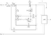
도1은 트라이액 조광기(TRIAC dimmer)의 내부 회로구성을 도시한 도면이다.1 is a diagram showing the internal circuit configuration of a triac dimmer.
트라이액 조광기의 기본 회로 구성 요소는 전위차계 저항(R1), 고정 레지스터 저항(R2), 커패시터(C1), 가변저항(W1), DIAC 및 TRIAC 으로 이루어져 있다.The basic circuit components of a triac dimmer consist of potentiometer resistor (R1), fixed resistor resistor (R2), capacitor (C1), variable resistor (W1), DIAC, and TRIAC.
R1, R2 및 C1으로 형성되는 RC 네트워크는 C1의 전압이 DIAC의 트리거 전압에 도달할 때까지 트라이액의 시동을 지연한다. 가변저항(W1)의 저항값이 증가하면 트라이액의 온타임 또는 ‘도통각(conduction angle)’을 감소시키는 시동 지연이 증가한다.The RC network formed by R1, R2 and C1 delays the start up of the triac until the voltage of C1 reaches the trigger voltage of the DIAC. Increasing the resistance of the variable resistor W1 increases the start-up delay, which reduces the on-time or 'conduction angle' of the triac.
조광기의 위상 제어는 W1과 C3에 의해 제어되며, 도통각의 크기는 W1 가변저항값의 변화에 의해 조절된다.The phase control of the dimmer is controlled by W1 and C3, and the magnitude of the conduction angle is adjusted by the change of the W1 variable resistance value.
즉, R2, R3, W1을 통해 흐르는 전류는 C3를 충전시키고, 이로 인해 충전된 전압이 DIAC의 BRAKE OVER 전압에 도달하게 되면, 트라이액의 게이트에 전류가 인가되어 TRIAC은 TURN ON 된다. 따라서 C3의 충전전류에 의해 TRIAC의 도통각이 조절되는 것이다.That is, the current flowing through R2, R3, and W1 charges C3. When the charged voltage reaches the BRAKE OVER voltage of DIAC, the current is applied to the gate of the triac, and the TRIAC is turned on. Therefore, the conduction angle of TRIAC is controlled by the charging current of C3.
도1을 기본으로 하여 트라이액 조광기의 기본 동작을 설명하면 다음과 같다.Referring to the basic operation of the triac dimmer based on Figure 1 as follows.
트라이액 는 게이트에 전류가 인가되면 바로 TURN ON 하여 조광기의 동작 전류(I)가 흐르게 된다. 여기서, 동작 전류(I)가 최소 홀딩전류(Ih) 미만으로 떨어지지 않아야 트라이액은 계속 TURN ON 상태를 유지한다.Triac turns on as soon as current is applied to the gate, and the operating current (I) of the dimmer flows. Here, the triac keeps the TURN ON state unless the operating current I falls below the minimum holding current Ih.
따라서, 트라이액 조광기의 동작 전류(I)가 홀딩전류(Ih) 이하가 되면 트라이액은 TURN OFF가 된다. 다시 트라이액을 TURN ON 상태로 만들기 위해서는 게이트에 전류를 다시 인가해 주어야 한다.Therefore, the triac turns TURN OFF when the operating current I of the triac dimmer becomes less than or equal to the holding current Ih. To turn the triac back on, you must reapply current to the gate.
그러므로 트라이액 조광기의 동작을 계속적으로 유지하기 위해서는 조광기의 동작 전류(I)를 항상 홀딩전류(Ih) 이상으로 유지시켜줘야 한다.Therefore, in order to continuously maintain the operation of the triac dimmer, the operating current I of the dimmer should always be kept above the holding current Ih.
여기서, 조광기의 동작 전류(I)는 조광기의 출력단에 걸리는 로드(10)에 의해서 조절될 수 있다.
Here, the operating current I of the dimmer may be adjusted by the
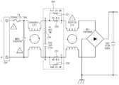
도2는 본 발명의 엘이디 조명장치의 구성을 도시한 도면이다.2 is a view showing the configuration of the LED lighting apparatus of the present invention.
본 발명의 트라이액 조광기를 포함하는 엘이디 조명장치는 트라이액 조광기(100), 부하단(200), 브리지 정류회로단(300) 및 엘이디단(400)을 포함한다.The LED lighting apparatus including the triac dimmer of the present invention includes a
트라이액 조광기(100)는 빛의 밝기를 조절하는 기능(조광기능)을 수행한다. 조광기능은 도1에서 상술한 가변저항값(W1)을 변화시켜서 조절할 수 있다.The
부하단(200)은 트라이액 조광기(100)의 출력단과 상기 브리지 정류회로단(300) 사이에 연결된다. 즉, 부하단(200)은 노드 A와 노드 C 사이, 및 노드 B 와 노드 D 사이에 연결된다.The
부하단(200)의 회로 구성에 대한 설명은 도3에서 후술하기로 한다.The circuit configuration of the
부하단(200)은 트라이액 조광기(100)의 낮은 조광 조절구간에서도 트라이액 조광기의 동작을 안정화 시킬 수 있다. 부하단(200)으로 인해 트라이액 조광기(100)의 낮은 조광 조절구간에서도 트라이액 조광기의 동작을 안정화 시킬수 있는 이유에 대해서는 도4에서 후술하기로 한다.The
브리지 정류회로단(300)은 엘이디단(400)에 전류를 공급하는 기능을 수행한다. 브리지 정류회로단(300)은 트라이액 조광기(100)로부터 전원을 공급받아 이를 정류하여 엘이디단(400)으로 전류를 공급한다.The bridge
엘이디단(400)은 전류를 공급받아 빛을 내는 기능을 수행하며, 하나 이상의 엘이디로 구성된다.
도3은 본 발명의 일 실시예로 부하단의 회로 구성을 나타낸 도면이다.3 is a diagram illustrating a circuit configuration of a load stage according to an embodiment of the present invention.
부하단(200)의 회로 구성은 상술한 바와 같이 트라이액 조광기(100)의 출력단(A, B)과 브리지 정류회로단(300)의 입력단(C,D) 상이에 연결된다.As described above, the circuit configuration of the
즉, 부하단(200)은 브리지 정류회로단(300)과 병렬로 연결되고 트라이액 조광기(100)의 출력단(A, B)과 연결된다.That is, the
부하단(200)의 내부 회로 구성은 다음과 같다.The internal circuit configuration of the
트라이액 조광기(100)의 출력단의 제1노드(A)와 트라이액 조광기(100)의 출력단의 제2노드(B) 사이에 연결되어 브리지 정류회로단(300)과 병렬로 구성되는 부하저항(210)을 포함한다.A load resistor connected in parallel with the bridge
여기서, 브리지 정류회로단(300)과 엘이디단(400)도 저항을 가진 부하로 볼수 있다. 따라서, 부하저항(210)이 브리지 정류회로단(300)과 엘이디단(400)과 병렬로 연결되므로 트라이액 조광기(100)의 출력단의 저항을 작아지게 된다.Here, the bridge
또한, 부하단(200)의 내부 회로 구성은 트라이액 조광기(100)의 출력단의 제1노드(A)와 브리지 정류회로단(300)의 제1노드(C) 사이에 연결되는 제1 댐핑저항(221, 222)과 트라이액 조광기(100)의 출력단의 제2노드(B)와 브리지 정류회로단(300)의 제2노드(D) 사이에 연결되는 제2 댐핑저항(231, 232)을 포함할 수 있다.In addition, the internal circuit configuration of the
제1 댐핑저항(221, 222) 및 제2 댐핑 저항(231, 232)을 구성하는 이유는 트라이액 조광기(100)의 출력단에서 출력되는 전압의 파형에 포함되어 있는 overshoot, undershoot 로 인한 노이즈를 제거하기 위함이다.The reason for configuring the first damping
여기서 제1 댐핑저항(221, 222) 및 제2 댐핑 저항(231, 232)은 각각 복수개의 저항이 병렬로 연결되어 구성할 수도 있다.
Here, the first damping
도4는 본 발명의 일 실시예로 부하단을 구성하는 경우에 조광 조절구간에서 트라이액 조광기의 동작전류를 도시한 도면이다.4 is a diagram illustrating an operating current of a triac dimmer in a dimming control section when configuring a load stage according to an embodiment of the present invention.
도4(a)는 부하단(200)을 구성하지 않은 경우의 조광 조절구간에서 트라이액 조광기의 동작전류를 도시한 도면이다.4 (a) is a diagram showing the operating current of the triac dimmer in the dimming control section when the
곡선은 트라이액 조광기의 동작전류를 도시한 것이고, 점선은 트라이액 조광기의 홀딩전류값을 나타낸 것이다.The curve shows the operating current of the triac dimmer and the dashed line shows the holding current value of the triac dimmer.
도4(a)에서는 부하단(200)을 구성하지 않은 경우, 조광 조절구간 중 최소 조광 레벌 구간(MIN)에서 트라이액 조광기의 동작전류가 트라이액 조광기의 홀딩전류값 이하로 떨어지는 것을 알 수 있다. 따라서 이러한 구간에서는 상술한 바와 같이 트라이액은 TURN OFF가 된다.In FIG. 4A, when the
도4(b)는 부하단(200)을 구성한 경우의 조광 조절구간에서 트라이액 조광기의 동작전류를 도시한 도면이다.4B is a diagram showing an operating current of the triac dimmer in the dimming control section when the
도4(b)에서는 부하단(200)을 구성한 경우, 조광 조절구간 중 최소 조광 레벌 구간(MIN)에서 트라이액 조광기의 동작전류가 트라이액 조광기의 홀딩전류값 이하로 떨어지지 않는 것을 알 수 있다. 따라서 이러한 구간에서도 트라이액은 TURN ON 상태를 유지 할 수 있다.
In FIG. 4B, when the
상기에서는 본 발명의 실시예를 참조하여 설명하였지만, 해당 기술 분야에서 통상의 지식을 가진 자라면 하기의 특허 청구의 범위에 기재된 본 발명의 사상 및 영역으로부터 벗어나지 않는 범위 내에서 본 발명을 다양하게 수정 및 변경시킬 수 있음을 이해할 수 있을 것이다.It will be apparent to those skilled in the art that various modifications and variations can be made in the present invention without departing from the spirit or scope of the invention as defined in the following claims And changes may be made without departing from the spirit and scope of the invention.
10 : LOAD 100 : 트라이액 조광기
200 : 부하단 210 : 부하저항
221, 222 : 제1 댐핑저항 231,232 : 제2 댐핑저항
300 : 브리지 정류회로단 400 : 엘이디단10: LOAD 100: Triac Dimmer
200: load stage 210: load resistance
221, 222: first damping
300: bridge rectifier circuit 400: LED stage
Claims (5)
Translated fromKorean상기 엘이디단의 빛의 세기를 조절하는 트라이액 조광기;
상기 트라이액 조광기의 출력단과 상기 브리지 정류회로단 사이에 연결되고 상기 트라이액 조광기의 낮은 조광 조절구간에서도 상기 트라이액 조광기의 동작을 안정화 시키는 부하단;
상기 부하단과 연결되어 상기 엘이디단으로 전원을 공급하는 브리지 정류회로단; 및
상기 브리지 정류회로단으로부터 동작 전원을 공급받는 상기 엘이디단;을 포함하되,
상기 부하단은 상기 출력단의 제1노드와 상기 출력단의 제2노드 사이에 연결되어, 상기 브리지 정류회로단과 병렬로 연결된 부하저항을 포함하고, 상기 부하저항의 제1노드단과 상기 브리지 정류회로단의 제1 노드 사이에 연결되는 제1 댐핑저항; 및 상기 부하저항의 제2노드단과 상기 브리지 정류회로단의 제2 노드 사이에 연결되는 제2 댐핑저항;을 포함하는 것을 특징으로 하는 엘이디 조명장치.
An LED lighting device comprising an LED stage, a bridge rectifying circuit stage, and a triac (triode for alternating current) dimmer,
Triac dimmer for controlling the intensity of the light of the LED stage;
A load stage connected between the output stage of the triac dimmer and the bridge rectifier circuit stage and stabilizing the operation of the triac dimmer even at a low dimming control section of the triac dimmer;
A bridge rectifier circuit stage connected to the load stage to supply power to the LED stage; And
And the LED stage supplied with operating power from the bridge rectifier circuit stage.
The load stage is connected between the first node of the output terminal and the second node of the output terminal, and includes a load resistor connected in parallel with the bridge rectifier circuit stage, the first node of the load resistance and the bridge rectifier circuit stage A first damping resistor connected between the first nodes; And a second damping resistor connected between the second node of the load resistor and the second node of the bridge rectifier circuit.
상기 제1 댐핑저항 또는 상기 제2 댐핑저항은 각각 복수개의 저항이 병렬로 연결되어 구성되는 것을 특징으로 하는 엘이디 조명장치.
The method of claim 1,
LED lighting device, characterized in that the first damping resistor or the second damping resistor is configured by connecting a plurality of resistors in parallel.
Priority Applications (10)
| Application Number | Priority Date | Filing Date | Title |
|---|---|---|---|
| KR1020120059977AKR101341976B1 (en) | 2012-06-04 | 2012-06-04 | LED Lighting device |
| EP17192653.8AEP3288346A1 (en) | 2012-06-04 | 2013-06-03 | Led lighting device |
| EP18172656.3AEP3399845A1 (en) | 2012-06-04 | 2013-06-03 | Led lighting device |
| CN201610710397.2ACN106304486B (en) | 2012-06-04 | 2013-06-03 | LED light device |
| JP2015514927AJP2015521362A (en) | 2012-06-04 | 2013-06-03 | LED lighting device |
| EP13800065.8AEP2858460B1 (en) | 2012-06-04 | 2013-06-03 | Led lighting device |
| CN201380025925.5ACN104303601B (en) | 2012-06-04 | 2013-06-03 | LED lighting |
| US14/405,246US9408263B2 (en) | 2012-06-04 | 2013-06-03 | LED lighting device |
| PCT/KR2013/004866WO2013183893A1 (en) | 2012-06-04 | 2013-06-03 | Led lighting device |
| US15/193,028US9713208B2 (en) | 2012-06-04 | 2016-06-25 | LED lighting device |
Applications Claiming Priority (1)
| Application Number | Priority Date | Filing Date | Title |
|---|---|---|---|
| KR1020120059977AKR101341976B1 (en) | 2012-06-04 | 2012-06-04 | LED Lighting device |
Publications (2)
| Publication Number | Publication Date |
|---|---|
| KR20130136284A KR20130136284A (en) | 2013-12-12 |
| KR101341976B1true KR101341976B1 (en) | 2013-12-16 |
Family
ID=49712245
Family Applications (1)
| Application Number | Title | Priority Date | Filing Date |
|---|---|---|---|
| KR1020120059977AActiveKR101341976B1 (en) | 2012-06-04 | 2012-06-04 | LED Lighting device |
Country Status (6)
| Country | Link |
|---|---|
| US (2) | US9408263B2 (en) |
| EP (3) | EP3399845A1 (en) |
| JP (1) | JP2015521362A (en) |
| KR (1) | KR101341976B1 (en) |
| CN (2) | CN106304486B (en) |
| WO (1) | WO2013183893A1 (en) |
Families Citing this family (4)
| Publication number | Priority date | Publication date | Assignee | Title |
|---|---|---|---|---|
| KR102246647B1 (en)* | 2014-06-12 | 2021-04-30 | 서울반도체 주식회사 | Ac driven led luminescent apparutus |
| TWI597930B (en)* | 2015-02-06 | 2017-09-01 | Use to change the conduction angle as the control command of the control device | |
| US10178717B2 (en) | 2017-03-09 | 2019-01-08 | Dongming Li | Lamp-control circuit for lamp array emitting constant light output |
| RU183081U1 (en)* | 2018-05-15 | 2018-09-10 | Владимир Филиппович Ермаков | Ermakov LED rectifier bridge |
Citations (2)
| Publication number | Priority date | Publication date | Assignee | Title |
|---|---|---|---|---|
| JP2004296205A (en)* | 2003-03-26 | 2004-10-21 | Matsushita Electric Works Ltd | LED dimming lighting device and lighting equipment |
| JP2011054537A (en)* | 2009-09-04 | 2011-03-17 | Toshiba Lighting & Technology Corp | Led lighting device and illumination apparatus |
Family Cites Families (17)
| Publication number | Priority date | Publication date | Assignee | Title |
|---|---|---|---|---|
| US6452343B2 (en)* | 1999-11-17 | 2002-09-17 | Koninklijke Philips Electronics N.V. | Ballast circuit |
| GB0617393D0 (en)* | 2006-09-04 | 2006-10-11 | Lutron Electronics Co | Variable load circuits for use with lighting control devices |
| US8035318B2 (en)* | 2008-06-30 | 2011-10-11 | Neptun Light, Inc. | Apparatus and method enabling fully dimmable operation of a compact fluorescent lamp |
| KR101055865B1 (en) | 2009-06-25 | 2011-08-09 | 박찬수 | Illuminance control system using magnetic ballast |
| KR20110019557A (en)* | 2009-08-20 | 2011-02-28 | 성호전자(주) | Flicker prevention circuit of SMPS for LED lighting combined with dimmer |
| US8664881B2 (en)* | 2009-11-25 | 2014-03-04 | Lutron Electronics Co., Inc. | Two-wire dimmer switch for low-power loads |
| JP5214585B2 (en)* | 2009-12-25 | 2013-06-19 | シャープ株式会社 | LED drive circuit, phase control dimmer, LED illumination lamp, LED illumination device, and LED illumination system |
| TW201141303A (en)* | 2010-05-07 | 2011-11-16 | Light Engine Ltd | Triac dimmable power supply unit for LED |
| WO2011148590A1 (en)* | 2010-05-26 | 2011-12-01 | パナソニック株式会社 | Led turn-on circuit, lamp, and illumination apparatus |
| JP5079855B2 (en)* | 2010-08-24 | 2012-11-21 | シャープ株式会社 | LED drive circuit and LED illumination lamp using the same |
| EP2692207B1 (en)* | 2011-03-28 | 2016-05-18 | Koninklijke Philips N.V. | Driving device and method for driving a load, in particular an led assembly |
| US8497637B2 (en) | 2011-04-13 | 2013-07-30 | Gang Gary Liu | Constant voltage dimmable LED driver |
| CN202135377U (en)* | 2011-07-21 | 2012-02-01 | 北京源点新智科技有限公司 | A control circuit of a drive power supply capable of adjusting an LED light source, and a control module thereof |
| US8624514B2 (en)* | 2012-01-13 | 2014-01-07 | Power Integrations, Inc. | Feed forward imbalance corrector circuit |
| US20140265898A1 (en)* | 2013-03-15 | 2014-09-18 | Power Integrations, Inc. | Lossless preload for led driver with extended dimming |
| JP6103478B2 (en)* | 2013-03-22 | 2017-03-29 | 東芝ライテック株式会社 | Power supply circuit and lighting device |
| WO2015056161A1 (en)* | 2013-10-15 | 2015-04-23 | Koninklijke Philips N.V. | Drive unit for a lighting element and operating method therefor |
- 2012
- 2012-06-04KRKR1020120059977Apatent/KR101341976B1/enactiveActive
- 2013
- 2013-06-03EPEP18172656.3Apatent/EP3399845A1/ennot_activeWithdrawn
- 2013-06-03USUS14/405,246patent/US9408263B2/enactiveActive
- 2013-06-03JPJP2015514927Apatent/JP2015521362A/enactivePending
- 2013-06-03WOPCT/KR2013/004866patent/WO2013183893A1/enactiveApplication Filing
- 2013-06-03CNCN201610710397.2Apatent/CN106304486B/ennot_activeExpired - Fee Related
- 2013-06-03CNCN201380025925.5Apatent/CN104303601B/ennot_activeExpired - Fee Related
- 2013-06-03EPEP17192653.8Apatent/EP3288346A1/ennot_activeWithdrawn
- 2013-06-03EPEP13800065.8Apatent/EP2858460B1/ennot_activeNot-in-force
- 2016
- 2016-06-25USUS15/193,028patent/US9713208B2/enactiveActive
Patent Citations (2)
| Publication number | Priority date | Publication date | Assignee | Title |
|---|---|---|---|---|
| JP2004296205A (en)* | 2003-03-26 | 2004-10-21 | Matsushita Electric Works Ltd | LED dimming lighting device and lighting equipment |
| JP2011054537A (en)* | 2009-09-04 | 2011-03-17 | Toshiba Lighting & Technology Corp | Led lighting device and illumination apparatus |
Also Published As
| Publication number | Publication date |
|---|---|
| KR20130136284A (en) | 2013-12-12 |
| EP2858460A4 (en) | 2016-05-25 |
| WO2013183893A1 (en) | 2013-12-12 |
| CN104303601A (en) | 2015-01-21 |
| EP2858460A1 (en) | 2015-04-08 |
| US20150156837A1 (en) | 2015-06-04 |
| CN106304486B (en) | 2019-01-15 |
| EP3399845A1 (en) | 2018-11-07 |
| EP3288346A1 (en) | 2018-02-28 |
| US20160309556A1 (en) | 2016-10-20 |
| EP2858460B1 (en) | 2017-09-27 |
| US9408263B2 (en) | 2016-08-02 |
| CN104303601B (en) | 2016-09-14 |
| JP2015521362A (en) | 2015-07-27 |
| US9713208B2 (en) | 2017-07-18 |
| CN106304486A (en) | 2017-01-04 |
Similar Documents
| Publication | Publication Date | Title |
|---|---|---|
| RU2638958C2 (en) | Circuit device and led lamp, containing this circuit device | |
| JP5746311B2 (en) | Adaptive holding current control for LED dimmer | |
| US9674918B2 (en) | Illumination system and luminaire | |
| JP5822670B2 (en) | LED lighting device | |
| KR101683438B1 (en) | Lighting system and control circuit thereof | |
| KR101341976B1 (en) | LED Lighting device | |
| KR20160014379A (en) | Lighting apparatus | |
| Eom et al. | Design optimization of TRIAC-dimmable AC-DC converter in LED lighting | |
| KR20170019943A (en) | Lighting apparatus | |
| CN111972048B (en) | Voltage transformer of lighting system | |
| CN210745620U (en) | LED driver circuit and control chip | |
| JP5473377B2 (en) | Light emitting element control circuit | |
| KR102352631B1 (en) | Circuit and method to control led lighting apparatus | |
| KR101326988B1 (en) | Bleed circuit, lighting control circuit and method thereof | |
| CN105530720A (en) | Driving device and method thereof | |
| JP6827199B2 (en) | Dimming control device, lighting equipment, and control method | |
| TWI612842B (en) | Light source driving circuit and light source module | |
| KR101597773B1 (en) | Power saving device og LED lighting fixtures | |
| KR20140107837A (en) | Led lighting system and control circuit thereof | |
| CN111246619B (en) | LED driver for phase-cut dimmer | |
| JP6176568B2 (en) | Lighting device and lighting apparatus | |
| KR101674501B1 (en) | Led lighting apparatus | |
| JP2021184361A (en) | Lighting equipment and lighting equipment | |
| TW201408129A (en) | LED control circuit and lighting device thereof | |
| JP2016201277A (en) | Lighting circuit, lighting fixture, and illumination system |
Legal Events
| Date | Code | Title | Description |
|---|---|---|---|
| A201 | Request for examination | ||
| PA0109 | Patent application | Patent event code:PA01091R01D Comment text:Patent Application Patent event date:20120604 | |
| PA0201 | Request for examination | ||
| E902 | Notification of reason for refusal | ||
| PE0902 | Notice of grounds for rejection | Comment text:Notification of reason for refusal Patent event date:20130726 Patent event code:PE09021S01D | |
| E701 | Decision to grant or registration of patent right | ||
| PE0701 | Decision of registration | Patent event code:PE07011S01D Comment text:Decision to Grant Registration Patent event date:20131128 | |
| GRNT | Written decision to grant | ||
| PR0701 | Registration of establishment | Comment text:Registration of Establishment Patent event date:20131210 Patent event code:PR07011E01D | |
| PR1002 | Payment of registration fee | Payment date:20131211 End annual number:3 Start annual number:1 | |
| PG1501 | Laying open of application | ||
| PG1601 | Publication of registration | ||
| FPAY | Annual fee payment | Payment date:20160906 Year of fee payment:4 | |
| PR1001 | Payment of annual fee | Payment date:20160906 Start annual number:4 End annual number:4 | |
| FPAY | Annual fee payment | Payment date:20170907 Year of fee payment:5 | |
| PR1001 | Payment of annual fee | Payment date:20170907 Start annual number:5 End annual number:5 | |
| FPAY | Annual fee payment | Payment date:20190909 Year of fee payment:7 | |
| PR1001 | Payment of annual fee | Payment date:20190909 Start annual number:7 End annual number:7 | |
| PR1001 | Payment of annual fee | Payment date:20210908 Start annual number:9 End annual number:9 | |
| PR1001 | Payment of annual fee | Payment date:20220906 Start annual number:10 End annual number:10 | |
| PR1001 | Payment of annual fee |