KR101340138B1 - Substrate holding device, exposure device, exposure method, and device fabrication method - Google Patents
Substrate holding device, exposure device, exposure method, and device fabrication methodDownload PDFInfo
- Publication number
- KR101340138B1 KR101340138B1KR1020087016430AKR20087016430AKR101340138B1KR 101340138 B1KR101340138 B1KR 101340138B1KR 1020087016430 AKR1020087016430 AKR 1020087016430AKR 20087016430 AKR20087016430 AKR 20087016430AKR 101340138 B1KR101340138 B1KR 101340138B1
- Authority
- KR
- South Korea
- Prior art keywords
- substrate
- circumferential wall
- space
- suction port
- holding device
- Prior art date
- Legal status (The legal status is an assumption and is not a legal conclusion. Google has not performed a legal analysis and makes no representation as to the accuracy of the status listed.)
- Expired - Fee Related
Links
Images


Classifications
- G—PHYSICS
- G03—PHOTOGRAPHY; CINEMATOGRAPHY; ANALOGOUS TECHNIQUES USING WAVES OTHER THAN OPTICAL WAVES; ELECTROGRAPHY; HOLOGRAPHY
- G03F—PHOTOMECHANICAL PRODUCTION OF TEXTURED OR PATTERNED SURFACES, e.g. FOR PRINTING, FOR PROCESSING OF SEMICONDUCTOR DEVICES; MATERIALS THEREFOR; ORIGINALS THEREFOR; APPARATUS SPECIALLY ADAPTED THEREFOR
- G03F7/00—Photomechanical, e.g. photolithographic, production of textured or patterned surfaces, e.g. printing surfaces; Materials therefor, e.g. comprising photoresists; Apparatus specially adapted therefor
- G03F7/70—Microphotolithographic exposure; Apparatus therefor
- G03F7/70216—Mask projection systems
- G03F7/70341—Details of immersion lithography aspects, e.g. exposure media or control of immersion liquid supply
- H—ELECTRICITY
- H01—ELECTRIC ELEMENTS
- H01L—SEMICONDUCTOR DEVICES NOT COVERED BY CLASS H10
- H01L21/00—Processes or apparatus adapted for the manufacture or treatment of semiconductor or solid state devices or of parts thereof
- H01L21/67—Apparatus specially adapted for handling semiconductor or electric solid state devices during manufacture or treatment thereof; Apparatus specially adapted for handling wafers during manufacture or treatment of semiconductor or electric solid state devices or components ; Apparatus not specifically provided for elsewhere
- H01L21/683—Apparatus specially adapted for handling semiconductor or electric solid state devices during manufacture or treatment thereof; Apparatus specially adapted for handling wafers during manufacture or treatment of semiconductor or electric solid state devices or components ; Apparatus not specifically provided for elsewhere for supporting or gripping
- H01L21/687—Apparatus specially adapted for handling semiconductor or electric solid state devices during manufacture or treatment thereof; Apparatus specially adapted for handling wafers during manufacture or treatment of semiconductor or electric solid state devices or components ; Apparatus not specifically provided for elsewhere for supporting or gripping using mechanical means, e.g. chucks, clamps or pinches
- H01L21/68714—Apparatus specially adapted for handling semiconductor or electric solid state devices during manufacture or treatment thereof; Apparatus specially adapted for handling wafers during manufacture or treatment of semiconductor or electric solid state devices or components ; Apparatus not specifically provided for elsewhere for supporting or gripping using mechanical means, e.g. chucks, clamps or pinches the wafers being placed on a susceptor, stage or support
- H01L21/6875—Apparatus specially adapted for handling semiconductor or electric solid state devices during manufacture or treatment thereof; Apparatus specially adapted for handling wafers during manufacture or treatment of semiconductor or electric solid state devices or components ; Apparatus not specifically provided for elsewhere for supporting or gripping using mechanical means, e.g. chucks, clamps or pinches the wafers being placed on a susceptor, stage or support characterised by a plurality of individual support members, e.g. support posts or protrusions
- G—PHYSICS
- G03—PHOTOGRAPHY; CINEMATOGRAPHY; ANALOGOUS TECHNIQUES USING WAVES OTHER THAN OPTICAL WAVES; ELECTROGRAPHY; HOLOGRAPHY
- G03F—PHOTOMECHANICAL PRODUCTION OF TEXTURED OR PATTERNED SURFACES, e.g. FOR PRINTING, FOR PROCESSING OF SEMICONDUCTOR DEVICES; MATERIALS THEREFOR; ORIGINALS THEREFOR; APPARATUS SPECIALLY ADAPTED THEREFOR
- G03F7/00—Photomechanical, e.g. photolithographic, production of textured or patterned surfaces, e.g. printing surfaces; Materials therefor, e.g. comprising photoresists; Apparatus specially adapted therefor
- G03F7/70—Microphotolithographic exposure; Apparatus therefor
- G03F7/70691—Handling of masks or workpieces
- G03F7/707—Chucks, e.g. chucking or un-chucking operations or structural details
- G—PHYSICS
- G03—PHOTOGRAPHY; CINEMATOGRAPHY; ANALOGOUS TECHNIQUES USING WAVES OTHER THAN OPTICAL WAVES; ELECTROGRAPHY; HOLOGRAPHY
- G03F—PHOTOMECHANICAL PRODUCTION OF TEXTURED OR PATTERNED SURFACES, e.g. FOR PRINTING, FOR PROCESSING OF SEMICONDUCTOR DEVICES; MATERIALS THEREFOR; ORIGINALS THEREFOR; APPARATUS SPECIALLY ADAPTED THEREFOR
- G03F7/00—Photomechanical, e.g. photolithographic, production of textured or patterned surfaces, e.g. printing surfaces; Materials therefor, e.g. comprising photoresists; Apparatus specially adapted therefor
- G03F7/70—Microphotolithographic exposure; Apparatus therefor
- G03F7/708—Construction of apparatus, e.g. environment aspects, hygiene aspects or materials
- G03F7/70858—Environment aspects, e.g. pressure of beam-path gas, temperature
- G03F7/70866—Environment aspects, e.g. pressure of beam-path gas, temperature of mask or workpiece
- G03F7/70875—Temperature, e.g. temperature control of masks or workpieces via control of stage temperature
- G—PHYSICS
- G03—PHOTOGRAPHY; CINEMATOGRAPHY; ANALOGOUS TECHNIQUES USING WAVES OTHER THAN OPTICAL WAVES; ELECTROGRAPHY; HOLOGRAPHY
- G03F—PHOTOMECHANICAL PRODUCTION OF TEXTURED OR PATTERNED SURFACES, e.g. FOR PRINTING, FOR PROCESSING OF SEMICONDUCTOR DEVICES; MATERIALS THEREFOR; ORIGINALS THEREFOR; APPARATUS SPECIALLY ADAPTED THEREFOR
- G03F7/00—Photomechanical, e.g. photolithographic, production of textured or patterned surfaces, e.g. printing surfaces; Materials therefor, e.g. comprising photoresists; Apparatus specially adapted therefor
- G03F7/70—Microphotolithographic exposure; Apparatus therefor
- G03F7/708—Construction of apparatus, e.g. environment aspects, hygiene aspects or materials
- G03F7/70908—Hygiene, e.g. preventing apparatus pollution, mitigating effect of pollution or removing pollutants from apparatus
- H—ELECTRICITY
- H01—ELECTRIC ELEMENTS
- H01L—SEMICONDUCTOR DEVICES NOT COVERED BY CLASS H10
- H01L21/00—Processes or apparatus adapted for the manufacture or treatment of semiconductor or solid state devices or of parts thereof
- H01L21/67—Apparatus specially adapted for handling semiconductor or electric solid state devices during manufacture or treatment thereof; Apparatus specially adapted for handling wafers during manufacture or treatment of semiconductor or electric solid state devices or components ; Apparatus not specifically provided for elsewhere
- H01L21/683—Apparatus specially adapted for handling semiconductor or electric solid state devices during manufacture or treatment thereof; Apparatus specially adapted for handling wafers during manufacture or treatment of semiconductor or electric solid state devices or components ; Apparatus not specifically provided for elsewhere for supporting or gripping
- H01L21/687—Apparatus specially adapted for handling semiconductor or electric solid state devices during manufacture or treatment thereof; Apparatus specially adapted for handling wafers during manufacture or treatment of semiconductor or electric solid state devices or components ; Apparatus not specifically provided for elsewhere for supporting or gripping using mechanical means, e.g. chucks, clamps or pinches
- H01L21/68714—Apparatus specially adapted for handling semiconductor or electric solid state devices during manufacture or treatment thereof; Apparatus specially adapted for handling wafers during manufacture or treatment of semiconductor or electric solid state devices or components ; Apparatus not specifically provided for elsewhere for supporting or gripping using mechanical means, e.g. chucks, clamps or pinches the wafers being placed on a susceptor, stage or support
- H01L21/68735—Apparatus specially adapted for handling semiconductor or electric solid state devices during manufacture or treatment thereof; Apparatus specially adapted for handling wafers during manufacture or treatment of semiconductor or electric solid state devices or components ; Apparatus not specifically provided for elsewhere for supporting or gripping using mechanical means, e.g. chucks, clamps or pinches the wafers being placed on a susceptor, stage or support characterised by edge profile or support profile
- Y—GENERAL TAGGING OF NEW TECHNOLOGICAL DEVELOPMENTS; GENERAL TAGGING OF CROSS-SECTIONAL TECHNOLOGIES SPANNING OVER SEVERAL SECTIONS OF THE IPC; TECHNICAL SUBJECTS COVERED BY FORMER USPC CROSS-REFERENCE ART COLLECTIONS [XRACs] AND DIGESTS
- Y10—TECHNICAL SUBJECTS COVERED BY FORMER USPC
- Y10T—TECHNICAL SUBJECTS COVERED BY FORMER US CLASSIFICATION
- Y10T279/00—Chucks or sockets
- Y10T279/11—Vacuum
Landscapes
- Engineering & Computer Science (AREA)
- Physics & Mathematics (AREA)
- General Physics & Mathematics (AREA)
- Condensed Matter Physics & Semiconductors (AREA)
- Manufacturing & Machinery (AREA)
- Computer Hardware Design (AREA)
- Microelectronics & Electronic Packaging (AREA)
- Power Engineering (AREA)
- Health & Medical Sciences (AREA)
- Epidemiology (AREA)
- Public Health (AREA)
- Life Sciences & Earth Sciences (AREA)
- Atmospheric Sciences (AREA)
- Environmental & Geological Engineering (AREA)
- Toxicology (AREA)
- Exposure And Positioning Against Photoresist Photosensitive Materials (AREA)
- Exposure Of Semiconductors, Excluding Electron Or Ion Beam Exposure (AREA)
- Container, Conveyance, Adherence, Positioning, Of Wafer (AREA)
Abstract
Translated fromKorean
Description
Translated fromKorean본 발명은 기판을 보지하는 기판 보지 장치, 액체를 거쳐 기판을 노광하는 노광 장치, 노광 방법 및 디바이스 제조 방법에 관한 것이다.The present invention relates to a substrate holding apparatus for holding a substrate, an exposure apparatus for exposing the substrate via a liquid, an exposure method, and a device manufacturing method.
포토리소그래피 공정에서 이용되는 노광 장치에 있어서, 하기 특허 문헌에 개시되어 있는 것과 같은 액체를 거쳐 기판을 노광하는 액침(液浸)식의 노광 장치가 알려져 있다.In the exposure apparatus used in a photolithography process, the liquid immersion type exposure apparatus which exposes a board | substrate through the liquid like that disclosed by the following patent document is known.
특허 문헌 1: 국제 공개 특허 공보 제99/49504호 팜플렛Patent Document 1: International Publication No. 99/49504 Pamphlet
특허 문헌 2: 일본 공개 특허 공보 제2004-289127호Patent Document 2: Japanese Unexamined Patent Publication No. 2004-289127
액침 노광 장치에 있어서는, 기판과 기판 스테이지 사이의 갭 등을 거쳐 액체가 기판의 이면 측의 공간에 침입하고, 그 액체가 기판의 이면에 부착되면, 여러 가지 문제가 발생할 가능성이 있다. 예컨대, 기판 이면의 소정 영역에 액체가 부착되면, 기판 스테이지의 홀더로 기판을 양호하게 보지할 수 없을 가능성이 있다. 또는, 반송 장치를 이용하여 홀더로부터 기판을 반출(언로딩)할 때, 기판의 이면에 접촉된 반송 장치에 액체가 부착되거나, 반송 경로로 액체가 비산하는 등, 피해가 확대할 가능성이 있다.In the liquid immersion exposure apparatus, when a liquid penetrates into the space on the back side of the substrate via a gap between the substrate and the substrate stage, and the liquid adheres to the back side of the substrate, various problems may occur. For example, when a liquid adheres to a predetermined region on the back surface of the substrate, there is a possibility that the substrate cannot be held well by the holder of the substrate stage. Or when carrying out (unloading) a board | substrate from a holder using a conveying apparatus, there exists a possibility that damage may enlarge, such as a liquid adhered to the conveying apparatus which contacted the back surface of a board | substrate, or a liquid scatters on a conveyance path | route.
본 발명은 기판 이면의 소정 영역에 액체가 부착되는 것을 억제할 수 있는 기판 보지 장치, 액체를 거쳐 기판을 노광하는 노광 장치, 노광 방법 및 그 노광 장치, 노광 방법을 이용하는 디바이스 제조 방법을 제공하는 것을 목적으로 한다.The present invention provides a substrate holding apparatus capable of suppressing adhesion of a liquid to a predetermined region on the back surface of a substrate, an exposure apparatus for exposing a substrate via a liquid, an exposure method and a device manufacturing method using the exposure apparatus and the exposure method. The purpose.
본 발명은 이하의 구성을 채용하고 있다.The present invention adopts the following configuration.
본 발명의 제 1 형태에 따르면, 노광 광이 조사되는 기판을 보지하는 기판 보지 장치로서, 기부와, 기부 상에 형성되고, 기판의 이면을 지지하는 지지부와, 기부 상에 형성되고, 지지부에 지지된 기판의 이면과 대향하는 제 1 상면을 갖고, 지지부에 지지된 기판과 기부 사이의 제 1 공간을 둘러싸는 제 1 주벽과, 기부 상에 형성되고, 지지부에 지지된 기판의 이면과 갭을 거쳐 대향하는 제 2 상면을 갖고, 제 1 주벽을 둘러싸는 제 2 주벽과, 기부 상에 형성되고, 지지부에 지지된 기판의 이면과 대향하는 제 3 상면을 갖고, 지지부 및 제 2 주벽을 둘러싸는 제 3 주벽과, 제 1 주벽과 제 2 주벽 사이의 제 2 공간으로 기체를 공급할 수 있는 유통구와, 제 2 주벽과 제 3 주벽 사이의 제 3 공간의 유체를 흡입하는 제 1 흡입구를 구비한 기판 보지 장치가 제공된다.According to the first aspect of the present invention, there is provided a substrate holding apparatus for holding a substrate to which exposure light is irradiated, the substrate holding portion formed on the base portion and supporting the back surface of the substrate, and formed on the base portion and supported on the supporting portion. A first circumferential wall having a first upper surface opposing the rear surface of the substrate, the first circumferential wall surrounding the first space between the substrate and the base supported on the support, and a back surface and a gap formed on the base and supported on the support; A second main wall having an opposing second upper surface, a second main wall surrounding the first circumferential wall, and a third upper surface formed on the base and opposing the back surface of the substrate supported on the support, and surrounding the support and the second main wall; Board holding provided with a 3 circumferential wall, a distribution port which can supply gas to a 2nd space between a 1st circumferential wall, and a 2nd circumferential wall, and a 1st suction port which inhales the fluid of a 3rd space between a 2nd main wall and a 3rd main wall. An apparatus is provided.
본 발명의 제 1 형태에 따르면, 기판 이면의 소정 영역에 액체가 부착되는 것을 억제할 수 있다.According to the first aspect of the present invention, it is possible to prevent the liquid from adhering to the predetermined region on the back surface of the substrate.
본 발명의 제 2 형태에 따르면, 상기 형태의 기판 보지 장치를 구비하고, 상기 기판 보지 장치에 보지된 기판을 액체를 거쳐 노광하는 노광 장치가 제공된다.According to the 2nd aspect of this invention, the exposure apparatus which comprises the board | substrate holding apparatus of the said aspect, and exposes the board | substrate held by the said board | substrate holding apparatus through a liquid is provided.
본 발명의 제 2 형태에 따르면, 기판 이면의 소정 영역에 액체가 부착되는 것을 억제할 수 있으므로, 기판을 양호하게 노광할 수 있다.According to the second aspect of the present invention, since the liquid can be prevented from adhering to the predetermined region on the back surface of the substrate, the substrate can be well exposed.
본 발명의 제 3 형태에 따르면, 상기 형태의 노광 장치를 이용하여 기판을 노광하는 것과, 상기 노광된 기판을 현상하는 것을 포함하는 디바이스 제조 방법이 제공된다.According to a third aspect of the present invention, there is provided a device manufacturing method comprising exposing a substrate using the exposure apparatus of the above aspect and developing the exposed substrate.
본 발명의 제 3 형태에 따르면, 기판을 양호하게 노광할 수 있는 노광 장치를 이용하여 디바이스를 제조할 수 있다.According to the 3rd aspect of this invention, a device can be manufactured using the exposure apparatus which can expose a board | substrate favorably.
본 발명의 제 4 형태에 따르면, 액침 노광을 행하는 노광 방법으로서, 기판 보지 장치에 기판을 보지하는 것과, 그 기판 보지 장치에 보지된 기판을 노광하는 것을 포함하고, 그 기판 보지 장치가, 기부와, 그 기부 상에 형성되고, 기판의 이면을 지지하는 지지부와, 그 기부 상에 형성되고, 그 지지부에 지지된 기판의 이면과 대향하는 제 1 상면을 가지며, 그 지지부에 지지된 기판과 그 기부 사이의 제 1 공간을 둘러싸는 제 1 주벽과, 그 기부 상에 형성되고, 그 지지부에 지지된 기판의 이면과 갭을 거쳐 대향하는 제 2 상면을 갖고, 그 제 1 주벽을 둘러싸는 제 2 주벽과, 그 기부 상에 형성되며, 그 지지부에 지지된 기판의 이면과 대향하는 제 3 상면을 갖고, 그 지지부 및 그 제 2 주벽을 둘러싸는 제 3 주벽과, 그 제 1 주벽과 그 제 2 주벽 사이의 제 2 공간에 기체를 공급할 수 있는 유통구와, 그 제 2 주벽과 그 제 3 주벽 사이의 제 3 공간의 유체를 흡입하는 제 1 흡입구를 구비하는 노광 방법이 제공된다.According to the 4th aspect of this invention, the exposure method which performs liquid immersion exposure includes holding a board | substrate to a board | substrate holding apparatus, and exposing the board | substrate held by the board | substrate holding apparatus, The board | substrate holding apparatus has a base and A substrate formed on the base and supporting a back surface of the substrate, and having a first upper surface formed on the base and opposed to the back surface of the substrate supported on the support, the substrate supported on the support and the base A second circumferential wall having a first circumferential wall surrounding the first space therebetween and a second upper surface formed on the base and opposed to the back surface of the substrate supported by the support portion, and facing the gap; And a third upper wall formed on the base and facing the back surface of the substrate supported by the support portion, the third main wall surrounding the support portion and the second circumferential wall, the first circumferential wall and the second circumferential wall; In the second space between The exposure method includes a first suction port for sucking a fluid that can supply the body flow port, and the second circumferential wall and that a third space between the
본 발명의 제 4 형태에 따르면, 기판 이면의 소정 영역에 액체가 부착되는 것을 억제하고, 액체를 거쳐 기판을 양호하게 노광할 수 있다.According to the 4th aspect of this invention, it can suppress that a liquid adheres to the predetermined area | region of the back surface of a board | substrate, and can expose a board | substrate favorable through a liquid.
본 발명의 제 5 형태에 따르면, 상기 형태의 노광 방법을 이용하여 기판을 노광하는 것과, 상기 노광된 기판을 현상하는 것을 포함하는 디바이스 제조 방법이 제공된다.According to a fifth aspect of the present invention, there is provided a device manufacturing method comprising exposing a substrate using the exposure method of the above aspect and developing the exposed substrate.
본 발명의 제 5 형태에 따르면, 기판을 양호하게 노광할 수 있는 노광 방법을 이용하여 디바이스를 제조할 수 있다.According to the 5th aspect of this invention, a device can be manufactured using the exposure method which can expose a board | substrate favorably.
본 발명에 따르면, 기판 이면의 소정 영역에 액체가 부착되는 것을 억제하여, 기판을 양호하게 노광할 수 있다.According to the present invention, the liquid can be prevented from adhering to a predetermined region on the back surface of the substrate, and the substrate can be well exposed.
도 1은 본 실시예에 따른 노광 장치를 나타내는 개략 구성도이다.1 is a schematic configuration diagram showing an exposure apparatus according to the present embodiment.
도 2는 본 실시예에 따른 테이블의 측단면도이다.2 is a side sectional view of a table according to the present embodiment.
도 3은 기판을 보지한 상태의 테이블의 평면도이다.3 is a plan view of a table in a state of holding a substrate.
도 4는 기판을 제외한 상태의 테이블의 평면도이다.4 is a plan view of a table without a substrate.
도 5는 기판 및 판 부재를 제외한 상태의 평면도이다.5 is a plan view of the state excluding the substrate and the plate member.
도 6은 본 실시예에 따른 테이블의 요부를 나타내는 측단면도이다.6 is a side sectional view showing a main portion of the table according to the present embodiment.
도 7은 본 실시예에 따른 테이블의 요부를 나타내는 평면도이다.7 is a plan view showing the main parts of the table according to the present embodiment.
도 8은 본 실시예에 따른 테이블의 동작을 설명하기 위한 모식도이다.8 is a schematic view for explaining the operation of the table according to the present embodiment.
도 9는 기체의 흐름을 설명하기 위한 모식도이다.9 is a schematic diagram for explaining the flow of gas.
도 10은 기체의 흐름을 설명하기 위한 모식도이다.10 is a schematic view for explaining the flow of gas.
도 11은 기체의 흐름을 설명하기 위한 모식도이다.It is a schematic diagram for demonstrating gas flow.
도 12a는 반송 장치로 기판의 이면을 보지하고 있는 상태를 나타내는 도면이다.It is a figure which shows the state which hold | maintains the back surface of a board | substrate with a conveyance apparatus.
도 12b는 반송 장치로 기판의 이면을 보지하고 있는 상태를 나타내는 도면이다.It is a figure which shows the state which hold | maintains the back surface of a board | substrate with a conveyance apparatus.
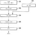
도 13은 마이크로 디바이스의 제조 공정의 일 예를 나타내는 흐름도이다.13 is a flowchart illustrating an example of a manufacturing process of a micro device.
(부호의 설명)(Explanation of Symbols)
1 : 액침 시스템4 : 기판 스테이지1: liquid immersion system 4: substrate stage
4T : 테이블7 : 제어 장치4T: Table 7: Control Unit
30 : 기재31 : 제 1 주벽30: base material 31: the first principal wall
31A : 제 1 상면32 : 제 2 주벽31A: First upper surface 32: Second circumferential wall
32A : 제 2 상면33 : 제 3 주벽32A: Second upper surface 33: Third circumferential wall
33A : 제 3 상면34 : 제 4 주벽33A: Third Top 34: Fourth Main Wall
34A : 제 4 상면37 : 슬릿34A: fourth upper surface 37: slit
41 : 제 1 공간42 : 제 2 공간41: first space 42: second space
43 : 제 3 공간44 : 제 4 공간43: third space 44: fourth space
51 : 제 1 홈52 : 제 2 홈51: the first groove 52: the second groove
53 : 제 3 홈60 : 유통구53: third home 60: distribution port
61 : 제 1 흡입구62 : 제 2 흡입구61: first suction port 62: second suction port
63 : 제 3 흡입구81 : 제 1 지지 부재63: third suction port 81: first support member
100 : 반송 장치EL : 노광 광100: conveying device EL: exposure light
EX : 노광 장치HD1 : 제 1 홀더EX: exposure apparatus HD1: first holder
LQ : 액체LR : 액침 영역LQ: Liquid LR: Liquid Immersion Area
P : 기판P: Substrate
이하, 본 발명의 실시예에 대하여 도면을 참조하면서 설명하지만, 본 발명은 이것에 한정되는 것은 아니다. 또한, 이하의 설명에서는, XYZ 직교 좌표계를 설정하고, 이 XYZ 직교 좌표계를 참조하면서 각 부재의 위치 관계에 대하여 설명한다. 그리고, 수평면 내에서의 소정 방향을 X축 방향, 수평면 내에서 X축 방향과 직교하는 방향을 Y축 방향, X축 방향 및 Y축 방향의 각각에 직교하는 방향(즉, 연직 방향)을 Z축 방향으로 한다. 또한, X축, Y축 및 Z축 주위의 회전(경사)방향을 각각 θX, θY 및 θZ 방향으로 한다.EMBODIMENT OF THE INVENTION Hereinafter, although the Example of this invention is described referring drawings, this invention is not limited to this. In addition, in the following description, the positional relationship of each member is demonstrated, setting an XYZ rectangular coordinate system and referring this XYZ rectangular coordinate system. The Z-axis is a direction orthogonal to each of the Y-axis direction, the X-axis direction, and the Y-axis direction in a direction perpendicular to the X-axis direction in the horizontal plane and the X-axis direction in the horizontal plane. Direction. Further, the rotation (tilt) directions around the X, Y, and Z axes are the θX, θY, and θZ directions, respectively.
도 1은 본 실시예에 대한 노광 장치(EX)를 나타내는 개략 구성도이다. 도 1에서, 노광 장치(EX)는 마스크(M)를 보지하여 이동 가능한 마스크 스테이지(3)와, 기판(P)을 보지하여 이동 가능한 기판 스테이지(4)와, 마스크 스테이지(3)에 보지되어 있는 마스크(M)를 노광 광(EL)으로 조명하는 조명계(IL)와, 노광 광(EL)으로 조명된 마스크(M)의 패턴 이미지를 기판(P) 상에 투영하는 투영 광학계(PL)와, 투영 광학계(PL)의 이미지면 근방의 노광 광(EL)의 광로 공간(K)을 액체(LQ)로 채우도록, 투영 광학계(PL)와 대향하는 물체(예컨대, 기판(P)) 상에 액침 영역(LR)을 형성하는 액침 시스템(1)과, 노광 장치(EX) 전체의 동작을 제어하는 제어 장치(7)를 구비하고 있다. 또한, 노광 장치(EX)는 기판 스테이지(4)에 기판(P)을 로딩함 과 아울러, 기판 스테이지(4)로부터 기판(P)을 언로딩하는 반송 장치(100)를 구비하고 있다.1 is a schematic configuration diagram showing an exposure apparatus EX according to the present embodiment. In FIG. 1, the exposure apparatus EX is held by a
여기서 말하는 기판은 반도체 웨이퍼 등의 기재 상에 감광재(포토 레지스트), 보호막 등의 막이 도포된 것을 포함한다. 마스크는 기판 상에 축소 투영되는 디바이스 패턴이 형성된 레티클을 포함한다. 또한, 본 실시예에 있어서는, 마스크로서 투과형 마스크를 이용하지만, 반사형 마스크를 이용하여도 좋다.The substrate referred to herein includes a film coated with a photosensitive material (photoresist), a protective film, or the like on a substrate such as a semiconductor wafer. The mask includes a reticle in which the device pattern is reduced-projected on the substrate. In this embodiment, a transmissive mask is used as the mask, but a reflective mask may be used.
조명계(IL)는 마스크(M) 상의 소정의 조명 영역을 균일한 조도 분포의 노광 광(EL)으로 조명하는 것이다. 조명계(IL)로부터 사출되는 노광 광(EL)으로는, 예컨대, 수은 램프로부터 사출되는 휘선(g선, h선, i선) 및 KrF 엑시머 레이저광(파장 248㎚) 등의 원자외광(DUV광), ArF 엑시머 레이저광(파장 193㎚) 및 F2 레이저광(파장 157㎚) 등의 진공자 외광(VUV광) 등이 이용된다. 본 실시예에 있어서는, 노광 광(EL)으로서, ArF 엑시머 레이저광이 이용된다.The illumination system IL illuminates the predetermined illumination area | region on the mask M with exposure light EL of uniform illuminance distribution. Examples of the exposure light EL emitted from the illumination system IL include ultraviolet light (g-ray, h-ray, i-ray) and KrF excimer laser light (wavelength 248 nm) emitted from a mercury lamp, for example. ), Vacuum ultraviolet light (VUV light) such as ArF excimer laser light (wavelength 193 nm) and F2 laser light (wavelength 157 nm), and the like. In the present embodiment, ArF excimer laser light is used as the exposure light EL.
마스크 스테이지(3)는, 리니어 모터 등의 액추에이터를 포함하는 마스크 스테이지 구동 장치에 의해, 마스크(M)를 보지한 상태로, X축, Y축 및 θZ 방향으로 이동 가능하다. 마스크 스테이지(3)(나아가서는 마스크(M))의 위치 정보는 레이저 간섭계(3L)에 의해 계측된다. 레이저 간섭계(3L)는 마스크 스테이지(3) 상에 마련된 반사면(3K)을 이용하여 마스크 스테이지(3)의 위치 정보를 계측한다. 제어 장치(7)는 레이저 간섭계(3L)의 계측 결과에 근거하여 마스크 스테이지 구동 장치를 제어하고, 마스크 스테이지(3)에 보지되어 있는 마스크(M)의 위치 제어를 행한다.The
또한, 반사경(3K)은 평면 거울만이 아니라 코너 큐브(레토로 리플렉터)를 포함하는 것으로 하여도 좋고, 반사경(3K)을 마스크 스테이지에 고정하여 설치하는 대신, 예컨대, 마스크 스테이지(3)의 단면(측면)을 경면 가공하여 반사면을 형성하여도 좋다. 또한, 마스크 스테이지(3)는, 예컨대, 일본 공개 특허 공보 평8-130179호(대응 미국 특허 제6,721,034호)에 개시되는 조동(粗動)/미동(微動) 가능한 구성으로 하여도 좋다.In addition, the reflecting
투영 광학계(PL)는 마스크(M)의 패턴 이미지를 소정의 투영 배율로 기판(P)에 투영하는 것으로서, 복수의 광학 소자를 갖고 있고, 그들 광학 소자는 경통(PK)에 보지되어 있다. 본 실시예의 투영 광학계(PL)는, 그 투영 배율이, 예컨대, 1/4, 1/5, 1/8 등의 축소계이며, 전술한 조명 영역과 공역인 투영 영역에 마스크 패턴의 축소 이미지를 형성한다. 또한, 투영 광학계(PL)는 축소계, 등배계 및 확대계의 어느 것이라도 좋다. 본 실시예에서는, 투영 광학계(PL)의 광축(AX)은 Z축 방향과 평행하게 되어 있다. 또한, 투영 광학계(PL)는 반사 광학 소자를 포함하지 않는 굴절계, 굴절 광학 소자를 포함하지 않는 반사계, 반사 광학 소자와 굴절 광학 소자를 포함하는 반사 굴절계의 어느 것이라도 좋다. 또한, 투영 광학계(PL)는 도립(倒立) 이미지와 정립(正立) 이미지의 어느 것을 형성하여도 좋다.The projection optical system PL projects the pattern image of the mask M onto the substrate P at a predetermined projection magnification, and has a plurality of optical elements, and these optical elements are held in the barrel PK. The projection optical system PL of this embodiment is a reduction system whose projection magnification is, for example, 1/4, 1/5, 1/8, etc., and reduces the reduced image of the mask pattern to the projection area which is conjugate with the aforementioned illumination area. Form. The projection optical system PL may be any of a reduction system, an equal magnification system, and an expansion system. In this embodiment, the optical axis AX of the projection optical system PL is parallel to the Z axis direction. The projection optical system PL may be any of a refractometer which does not include a reflective optical element, a reflectometer that does not contain a refractive optical element, and a reflection refractometer including a reflective optical element and a refractive optical element. In addition, the projection optical system PL may form either an inverted image or an upright image.
기판 스테이지(4)는 스테이지 본체(4B)와, 스테이지 본체(4B) 상에 탑재된 테이블(4T)과, 테이블(4T)에 마련되어, 기판(P)을 착탈 가능하게 보지하는 제 1 홀더(HD1)와, 제 1 홀더(HD1)에 보지된 기판(P)의 주위를 둘러싸도록 배치되는 판 부재(T)와, 테이블(4T)에 마련되고, 판 부재(T)를 착탈 가능하게 보지하는 제 2 홀 더(HD2)를 구비하고 있다.The board |
스테이지 본체(4B)는 에어 베어링(4A)에 의해, 베이스 부재(BP)의 상면(가이드면)에 대하여 비접촉 지지되어 있다. 베이스 부재(BP)의 상면은 XY 평면과 거의 평행하며, 기판 스테이지(4)는 베이스 부재(BP) 상에서 XY 방향으로 이동 가능하다.The stage
기판 스테이지(4)는, 리니어 모터 등의 액추에이터를 포함하는 기판 스테이지 구동 장치에 의해, 제 1 홀더(HD1)에 기판(P)을 보지한 상태로, 베이스 부재(BP) 상에서 이동 가능하다. 기판 스테이지 구동 장치는 스테이지 본체(4B)를 베이스 부재(BP) 상에서 X축 방향, Y축 방향 및 θZ 방향으로 이동함으로써, 그 스테이지 본체(4B) 상에 탑재되어 있는 테이블(4T)을 X축 방향, Y축 방향 및 θZ 방향으로 이동 가능한 제 1 구동계와, 스테이지 본체(4B)에 대하여 테이블(4T)을 Z축 방향, θX 방향 및 θY 방향으로 이동 가능한 제 2 구동계를 구비하고 있다.The board |
제 1 구동계는 리니어 모터 등의 액추에이터를 포함한다. 제 2 구동계는 스테이지 본체(4B)와 테이블(4T) 사이에 개재된, 예컨대, 보이스 코일 모터 등의 액추에이터(4V)와, 각 액추에이터의 구동량을 계측하는 도시하지 않은 계측 장치(인코더 등)를 포함한다. 테이블(4T)은 적어도 3개의 액추에이터(4V)에 의해 스테이지 본체(4B) 상에 지지된다. 액추에이터(4V) 각각은 스테이지 본체(4B)에 대하여 테이블(4T)을 Z축 방향으로 독립 구동 가능하고, 제어 장치(7)는 3개의 액추에이터(4V) 각각의 구동량을 조정함으로써, 스테이지 본체(4B)에 대하여 테이블(4T)을 Z축 방향, θX 방향 및 θY 방향으로 구동한다. 이와 같이, 제 1, 제 2 구동계를 포함하는 기판 스테이지 구동 장치는 기판 스테이지(4)의 테이블(4T)을 X축, Y축, Z축, θX, θY 및 θZ 방향의 6자유도의 방향으로 이동시킬 수 있다. 제어 장치(7)는 기판 스테이지 구동 장치를 제어함으로써, 테이블(4T)의 제 1 홀더(HD1)에 보지된 기판(P) 표면의 X축, Y축, Z축, θX, θY 및 θZ 방향의 6자유도의 방향에 관한 위치를 제어할 수 있다.The first drive system includes an actuator such as a linear motor. The second drive system includes an
기판 스테이지(4)의 테이블(4T)(나아가서는 기판(P))의 위치 정보는 레이저 간섭계(4L)에 의해 계측된다. 레이저 간섭계(4L)는 테이블(4T)에 마련된 반사면(4K)을 이용하여, 테이블(4T)의 X축, Y축 및 θZ 방향에 관한 위치 정보를 계측한다. 또한, 테이블(4T)의 제 1 홀더(HD1)에 보지되어 있는 기판(P) 표면의 면 위치 정보(Z축, θX 및 θY 방향에 관한 위치 정보)는 도시하지 않은 포커스·레벨링 검출계에 의해 검출된다. 제어 장치(7)는 레이저 간섭계(4L)의 계측 결과 및 포커스·레벨링 검출계의 검출 결과에 근거하여, 기판 스테이지 구동 장치를 제어하고, 제 1 홀더(HD1)에 보지되어 있는 기판(P)의 위치 제어를 행한다.The positional information of the table 4T (the further substrate P) of the
포커스·레벨링 검출계는 그 복수의 계측점에서 각각 기판의 Z축 방향의 위치 정보를 계측함으로써, 기판의 θX 및 θY 방향의 경사 정보(회전각)를 검출하는 것이다. 또한, 예컨대, 레이저 간섭계가 기판의 Z축, θX 및 θY 방향의 위치 정보를 계측 가능할 때는, 기판의 노광 동작 중에 그 Z축 방향의 위치 정보가 계측 가능해지도록 포커스·레벨링 검출계를 마련하지 않더라도 좋고, 적어도 노광 동작 중에는 레이저 간섭계의 계측 결과를 이용하여 Z축, θX 및 θY 방향에 관한 기판(P)의 위치 제어를 행하도록 하여도 좋다.The focus leveling detection system detects the inclination information (rotation angle) in the θX and θY directions of the substrate by measuring the positional information in the Z-axis direction of the substrate at each of the plurality of measurement points. For example, when the laser interferometer can measure the positional information in the Z-axis, θX and θY directions of the substrate, the focus leveling detection system may not be provided so that the positional information in the Z-axis direction can be measured during the exposure operation of the substrate. At least during the exposure operation, the position control of the substrate P in the Z-axis, θX, and θY directions may be performed using the measurement result of the laser interferometer.
액침 시스템(1)은 투영 광학계(PL)의 이미지면 근방의 노광 광(EL)의 광로 공간(K)을 액체(LQ)로 채운다. 예컨대, 기판(P)의 노광 중, 액침 시스템(1)은 투영 광학계(PL)의 복수의 광학 소자 중, 투영 광학계(PL)의 이미지면에 가장 가까운 최종 광학 소자(FL)의 하면과, 그 최종 광학 소자(FL)와 대향하는 위치에 배치된 기판 스테이지(4)(제 1 홀더(HD1)) 위의 기판(P)의 표면과의 사이의 노광 광(EL)의 광로 공간(K)을 액체(LQ)로 채우도록, 기판(P) 상에 액침 영역(LR)을 형성한다. 본 실시예에서는, 액체(LQ)로서, 물(순수)이 이용된다.The
액침 시스템(1)은 노광 광(EL)의 광로 공간(K)의 근방에 마련되고, 그 광로 공간(K)에 대하여 액체(LQ)를 공급하기 위한 공급구(12) 및 액체(LQ)를 회수하기 위한 회수구(22)를 갖는 노즐 부재(70)와, 공급관(13) 및 노즐 부재(70)의 내부에 형성된 공급 유로를 거쳐 공급구(12)에 액체(LQ)를 공급하는 액체 공급 장치(11)와, 노즐 부재(70)의 회수구(22)로부터 회수된 액체(LQ)를, 노즐 부재(70)의 내부에 형성된 회수 유로 및 회수관(23)을 거쳐 회수하는 액체 회수 장치(21)를 구비하고 있다. 본 실시예에 있어서는, 노즐 부재(70)는 노광 광(EL)의 광로 공간(K)을 둘러싸도록 환형으로 마련된다. 액체(LQ)를 공급하는 공급구(12)는 노광 광(EL)의 광로 공간(K)의 근방에 마련된다. 액체(LQ)를 회수하는 회수구(22)는 노즐 부재(70)의 하면에 마련되어 있고, 예컨대, 기판(P)의 노광 중에는, 기판(P)의 표면과 대향한다. 본 실시예에 있어서는, 회수구(22)는 노광 광(EL)의 광로 공간(K)에 대하여 공급구(12)보다 멀리 마련된다. 또한, 본 실시예에 있어서는, 회수구(22)에는 다공 부재(mesh)가 배치된다.The
액체 공급 장치(11)는 공급하는 액체(LQ)의 온도를 조정하는 온도 조정 장치, 액체(LQ) 중의 기체 성분을 저감하는 탈기 장치 및 액체(LQ) 중의 이물질을 제거하는 필터 유닛 등을 구비하고, 청정으로 온도 조정된 액체(LQ)를 송출할 수 있다. 또한, 액체 회수 장치(21)는 진공계 등을 구비하고, 액체(LQ)를 회수할 수 있다. 액체 공급 장치(11) 및 액체 회수 장치(21)를 포함하는 액침 시스템(1)의 동작은 제어 장치(7)로 제어된다. 액체 공급 장치(11)로부터 송출된 액체(LQ)는 공급관(13) 및 노즐 부재(70)의 공급 유로를 흐른 후, 공급구(12)로부터 노광 광(EL)의 광로 공간(K)으로 공급된다. 또한, 액체 회수 장치(21)를 가동함으로써 회수구(22)로부터 회수된 액체(LQ)는 노즐 부재(70)의 회수 유로를 흐른 후, 회수관(23)을 거쳐 액체 회수 장치(21)로 회수된다. 제어 장치(7)는 액침 시스템(1)을 제어하여, 액체 공급 장치(11)에 의한 액체 공급 동작과 액체 회수 장치(21)에 의한 액체 회수 동작을 병행해서 실행함으로써 노광 광(EL)의 광로 공간(K)을 액체(LQ)로 채우도록, 종단 광학 소자(FL)와 대향하는 물체(예컨대, 기판(P)) 상에 액체(LQ)의 액침 영역(LR)을 형성한다.The
노광 장치(EX)는 투영 광학계(PL)와 노광 광(EL)의 광로 공간(K)에 채워진 액체(LQ)를 거쳐 마스크(M)를 통과한 노광 광(EL)을 제 1 홀더(HD1)에 보지된 기판(P) 상에 조사함으로써, 마스크(M)의 패턴 이미지를 기판(P) 상에 투영하여, 기판(P)을 노광한다. 또한, 본 실시예의 노광 장치(EX)는, 기판(P)의 노광 중에, 최종 광학 소자(FL)와 기판(P) 사이의 노광 광(EL)의 광로 공간(K)을 액체(LQ)로 채움과 아울러, 투영 광학계(PL)의 투영 영역(AR)을 포함하는 기판(P) 상의 일부 영 역에, 투영 영역(AR)보다 크고, 또한 기판(P)보다 작은 액체(LQ)의 액침 영역(LR)을 국소적으로 형성하는 국소 액침 방식을 채용하고 있다.The exposure apparatus EX passes the exposure light EL that has passed through the mask M through the liquid LQ filled in the optical path space K of the projection optical system PL and the exposure light EL. By irradiating onto the board | substrate P hold | maintained in the pattern image, the pattern image of the mask M is projected on the board | substrate P, and the board | substrate P is exposed. In the exposure apparatus EX of the present embodiment, the optical path space K of the exposure light EL between the final optical element FL and the substrate P is converted into the liquid LQ during the exposure of the substrate P. FIG. In addition, the liquid immersion region of the liquid LQ larger than the projection region AR and smaller than the substrate P is filled in a part of the area on the substrate P including the projection region AR of the projection optical system PL. A local liquid immersion method is formed to locally form (LR).
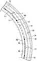
다음에, 본 실시예에 대한 테이블(4T)에 대하여, 도 1 내지 도 7을 참조하여 설명한다. 도 2는 제 1 홀더(HD1)로 기판(P)을 보지한 상태의 테이블(4T)의 측단면도, 도 3은 제 1 홀더(HD1)로 기판(P)을 보지한 상태의 테이블(4T)을 위쪽으로부터 본 평면도, 도 4는 기판(P)을 제 1 홀더(HD1)로부터 제외한 상태의 테이블(4T)을 위쪽으로부터 본 평면도, 도 5는 기판(P) 및 판 부재(T)를 제 1, 제 2 홀더(HD1, HD2)로부터 제외한 상태의 평면도, 도 6은 제 1 홀더(HD1)의 일부를 확대한 측단면도, 도 7은 평면도이다.Next, the table 4T according to the present embodiment will be described with reference to FIGS. 1 to 7. 2 is a side cross-sectional view of the table 4T in a state where the substrate P is held by the first holder HD1, and FIG. 3 is a table 4T in a state where the substrate P is held by the first holder HD1. 4 is a plan view of the table 4T with the substrate P removed from the first holder HD1, and FIG. 5 is a plan view of the substrate P and the plate member T, respectively. , A plan view of the state removed from the second holders HD1 and HD2, FIG. 6 is a side sectional view in which a part of the first holder HD1 is enlarged, and FIG. 7 is a plan view.
도 2 등에 나타내는 바와 같이, 테이블(4T)은 기재(30)와, 기재(30)에 마련되어, 기판(P)을 착탈 가능하게 보지하는 제 1 홀더(HD1)와, 기재(30)에 마련되어, 판 부재(T)를 착탈 가능하게 보지하는 제 2 홀더(HD2)를 구비하고 있다. 제 2 홀더(HD2)에 보지된 판 부재(T)는 제 1 홀더(HD1)에 보지된 기판(P)의 주위를 둘러싸도록 배치된다.As shown in FIG. 2 etc., the table 4T is provided in the
제 1 홀더(HD1)에 대하여 설명한다. 도 2 내지 도 7에 나타내는 바와 같이, 제 1 홀더(HD1)는 기재(30) 상에 형성되어 기판(P) 이면을 지지하는 제 1 지지 부재(81)와, 기재(30) 상에 형성되어 제 1 지지 부재(81)에 지지된 기판(P)의 이면과 대향하는 제 1 상면(31A)을 갖고, 제 1 지지 부재(81)에 지지된 기판(P)과 기재(30) 사이의 제 1 공간(41)을 둘러싸도록 마련된 제 1 주벽(31)과, 기재(30) 상에 형성되어 제 1 지지 부재(81)에 지지된 기판(P)의 이면과 대향하는 제 2 상 면(32A)을 갖고, 제 1 주벽(31)을 둘러싸도록 마련된 제 2 주벽(32)과, 기재(30) 상에 형성되어 제 1 지지 부재(81)에 지지된 기판(P)의 이면과 대향하는 제 3 상면(33A)을 갖고, 제 1 지지 부재(81) 및 제 2 주벽(32)을 둘러싸도록 마련된 제 3 주벽(33)과, 제 1 주벽(31)과 제 2 주벽(32) 사이의 제 2 공간(42)에 기체를 공급할 수 있는 유통구(60)와, 제 2 주벽(32)과 제 3 주벽(33) 사이의 제 3 공간(43)의 유체를 흡입하는 제 1 흡입구(61)를 구비하고 있다.The first holder HD1 will be described. 2 to 7, the first holder HD1 is formed on the
제 1 주벽(31)은 기판(P)의 외형과 거의 동일 형상의 환형(실질적으로 원형 환형)을 갖는다. 제 1 주벽(31)의 제 1 상면(31A)은 제 1 지지 부재(81)에 지지된 기판(P) 이면의 가장자리에 상대적으로 가까운 영역과 대향하도록 마련된다. 제 1 홀더(HD1)에 보지된 기판(P) 이면 측에는, 기판(P)의 이면과 제 1 주벽(31)과 기재(30)로 둘러싸인 제 1 공간(41)이 형성된다.The first
제 2 주벽(32)은 제 1 공간(41)에 대하여 제 1 주벽(31)의 외부에서 제 1 주벽(31)을 따라 형성된다. 제 1 주벽(31)과 제 2 주벽(32)은 소정의 간격(예컨대, 1㎜)만큼 이격되어 있다. 제 2 주벽(32)도 기판(P)의 외형과 거의 동일 형상의 환형(실질적으로 원형 환형)을 갖는다. 제 2 주벽(32)의 제 2 상면(32A)은 제 1 지지 부재(81)에 지지된 기판(P) 이면의 가장자리에 상대적으로 가까운 영역과 대향하도록 마련된다. 제 1 홀더(HD1)에 보지된 기판(P) 이면 측에는, 기판(P)의 이면과 제 1 주벽(31)과 제 2 주벽(32)과 기재(30)로 둘러싸인 제 2 공간(42)이 형성된다.The second
제 3 주벽(33)은 제 1 공간(41)에 대하여 제 1 주벽(31) 및 제 2 주벽(32)의 외부에, 제 2 주벽(32)으로부터 소정 거리만큼 이격하여 형성되어 있다. 제 3 주벽(33)도 기판(P)의 외형과 거의 동일 형상의 환형(실질적으로 원형 환형)을 갖는다. 제 3 주벽(33)의 제 3 상면(33A)은 제 1 지지 부재(81)에 지지된 기판(P) 이면의 가장자리 영역(에지 영역)과 대향하도록 마련된다. 제 1 홀더(HD1)에 보지된 기판(P)의 이면 측에는, 기판(P)의 이면과 제 2 주벽(32)과 제 3 주벽(33)과 기재(30)로 둘러싸인 제 3 공간(43)이 형성된다.The third
상술한 바와 같이, 제 1, 제 2, 제 3 주벽(31, 32, 33)은 모두 제 1 지지 부재(81)에 지지된 기판(P) 이면의 에지 영역, 또는 그 에지 영역에 가까운 영역과 대향하도록 마련된다.As described above, the first, second, and third
본 실시예에 있어서는, 제 1, 제 2, 제 3 주벽(31, 32, 33)은 거의 동심(同心)이 되도록 배치되어 있다. 제 1 홀더(HD1)는 제 1 공간(41)의 중심과, 기판(P) 이면의 중심이 거의 일치하도록 기판(P)을 보지한다.In this embodiment, the first, second, and third
또한, 본 실시예에 있어서는, 제 3 주벽(33)의 외경은 기판(P)의 외경보다 작다. 환언하면, 제 3 주벽(33)은 제 1 지지 부재(81)에 지지된 기판(P)의 에지보다 내측(기판(P)의 중심측)에 마련된다. 제 1 지지 부재(81)에 지지된 기판(P)의 에지 영역의 일부는 제 3 주벽(33)의 외측에 소정량 오버행(overhang)하고 있다. 이하의 설명에서는, 기판(P) 이면의, 제 3 주벽(33)보다 외측으로 오버행한 영역을 적절히, 오버행 영역(H1)(도 6 참조)이라 한다. 본 실시예에 있어서는, 오버행 영역(H1)의 폭은 약 1.5㎜이다.In addition, in the present embodiment, the outer diameter of the third
도 6에 나타내는 바와 같이, 본 실시예에 있어서는, 제 1 홀더(HD1)에 지지 된 기판(P)의 이면과 제 1 주벽(31)의 제 1 상면(31A) 사이에는, 제 1 갭(G1)이 형성된다. 또한, 제 1 홀더(HD1)에 지지된 기판(P)의 이면과 제 2 주벽(32)의 제 2 상면(32A) 사이에는, 제 2 갭(G2)이 형성된다. 제 3 주벽(33)은 제 1 홀더(HD1)에 지지된 기판(P)의 이면과 제 3 상면(33A)이 접촉하도록 형성되어 있다.As shown in FIG. 6, in the present embodiment, the first gap G1 is provided between the rear surface of the substrate P supported by the first holder HD1 and the first
본 실시예에 있어서는, 제 1 갭(G1)은 약 2∼10㎛이며, 제 2 갭(G2)도 약 2∼10㎛이다. 또한, 본 실시예에 있어서는, 제 1, 제 2, 제 3 상면(31A, 32A, 33A)의 폭은 약 0.5㎜이다.In this embodiment, the first gap G1 is about 2 to 10 mu m, and the second gap G2 is also about 2 to 10 mu m. In the present embodiment, the widths of the first, second, and third
유통구(60)는 제 2 공간(42)과 접속되어 있다. 도 4, 도 5, 도 7 등에 나타내는 바와 같이, 본 실시예에 있어서는, 유통구(60)는 제 1 주벽(31)과 제 2 주벽(32) 사이의 기재(30) 상에서 제 1 주벽(31)을 둘러싸도록, 제 1 주벽(31)의 외부에서 둘레 방향으로 소정 간격을 두고 복수 형성되어 있다. 본 실시예에 있어서는, 유통구(60)의 형상은 각각 원 형상이지만, 다각형 형상 등이라도 좋다. 또한, 본 실시예에 있어서는, 유통구(60)는 거의 등 간격으로 배치되어 있다.The
도 6 등에 나타내는 바와 같이, 제 2 공간(42)과 외부 공간(대기 공간)은 유통구(60)를 거쳐 접속되어 있다. 즉, 유통구(60) 및 그 유통구(60)에 접속하는 유로(60R)를 거쳐, 제 2 공간(42)과 외부 공간 사이에서 기체가 유통할 수 있다. 제 2 공간(42)은 유통구(60)를 거쳐 대기 개방되어 있다.As shown in FIG. 6 etc., the
본 실시예에 있어서는, 제 1 주벽(31)과 제 2 주벽(32) 사이의 기재(30) 상에는, 제 1 주벽(31)을 둘러싸도록, 제 1 주벽(31)의 외부에서 제 1 주벽(31)을 따라 환형의 제 1 홈(51)이 형성되어 있다. 유통구(60)는 제 1 홈(51)의 내측(제 1 홈(51)의 바닥부)에 형성되어 있다.In the present embodiment, on the base 30 between the first
도 1 및 도 6 등에 나타내는 바와 같이, 기재(30)의 제 2 주벽(32)과 제 3 주벽(33) 사이에 형성되어 있는 제 1 흡입구(61)는 진공계 등을 포함하는 제 1 흡입 장치(91)와 유로(61R)를 거쳐 접속되어 있다. 또한, 제 1 흡입구(61)는 제 3 공간(43)과 접속되어 있다. 제어 장치(7)는, 제 1 흡입 장치(91)를 구동함으로써, 제 3 공간(43)의 유체(기체 및 액체의 적어도 한쪽을 포함함)를 흡입한다.As shown in FIG. 1, FIG. 6, etc., the
본 실시예에 있어서는, 제 1 흡입구(61)는 제 2 주벽(32)과 제 3 주벽(33) 사이의 기재(30) 상에서 제 2 주벽(32)을 둘러싸도록, 제 2 주벽(32)의 외부에서 둘레 방향으로 소정 간격을 두고 복수 형성되어 있다. 본 실시예에 있어서는, 제 1 흡입구(61)의 형상은 각각 원 형상이지만, 다각형 형상 등이라도 좋다. 또한, 본 실시예에 있어서는, 제 1 흡입구(61)는 거의 등 간격으로 배치되어 있다.In the present embodiment, the
또한, 본 실시예에 있어서는, 제 2 주벽(32)과 제 3 주벽(33) 사이의 기재(30) 상에는, 제 2 주벽(32)을 둘러싸도록, 제 2 주벽(32)을 따라 환형의 제 2 홈(52)이 형성되어 있다. 제 1 흡입구(61)는 제 2 홈(52)의 내측(제 2 홈(52)의 바닥부)에 형성되어 있다.In addition, in the present embodiment, on the
제 1 지지 부재(81)는 기재(30)의 상면에 형성된 핀 형상의 돌기부이며, 기재(30) 상면의 복수의 소정 위치의 각각에 배치되어 있다. 본 실시예에 있어서는, 제 1 지지 부재(81)는 제 1 주벽(31)의 내측에 복수 배치되어 있다. 또한, 제 1 지지 부재(81)는 제 2 주벽(32)과 제 2 홈(52) 사이 및 제 2 홈(52)과 제 3 주벽(33) 사이에 복수 배치되어 있다.The
또한, 도 4, 도 5에 있어서는, 간략화를 위해, 제 3 공간(43) 내의 제 1 지지 부재(81)가 생략되어 있다. 단, 기판(P) 표면(Pa)의 충분한 평탄성을 확보할 수 있는 경우에는, 제 3 공간(43)에 제 1 지지 부재(81)를 마련하지 않아도 좋다.In addition, in FIG. 4, FIG. 5, the
기재(30) 상에는, 제 1 공간(41) 및 제 3 공간(43)을 대기압에 비해 부압의 공간으로 하기 위해 유체(주로 기체)를 흡입하는 제 2 흡입구(62)가 복수 마련된다. 제 2 흡입구(62)는 제 1 주벽(31)의 내측 및 제 2 주벽(32)과 제 3 주벽(33) 사이에 마련된다. 제 2 흡입구(62)는 오로지 기판(P)을 흡착 보지하기 위해 사용된다.On the
제 1 주벽(31)의 내측에서, 제 2 흡입구(62)는 제 1 지지 부재(81) 이외의 복수의 소정 위치에 각각 형성되어 있다. 또한, 제 2 주벽(32)과 제 3 주벽(33) 사이에 있고, 제 2 흡입구(62)는 제 2 주벽(32)에 대하여 제 1 흡입구(61)보다 떨어진 위치에 형성되어 있다. 즉, 제 2 흡입구(62)는 기재(30) 상면의 제 2 주벽(32)과 제 3 주벽(33) 사이에서, 제 2 주벽(32)과 제 2 홈(52) 사이에는 마련되지 않고, 제 2 홈(52)과 제 3 주벽(33) 사이의 소정 위치에 복수 마련된다.Inside the first
또한, 도 2, 도 4, 도 5에 있어서는, 간략화를 위해, 제 2 홈(52)과 제 3 주벽(33) 사이에 마련된 제 2 흡입구(62)가 생략되어 있다. 단, 제 1 주벽(31)의 내측에 마련된 제 2 흡입구(62)만으로 기판(P) 표면(Pa)의 충분한 평탄성이 확보되고, 기판(P)이 움직이지 않도록 보지할 수 있으면, 제 2 홈(52)과 제 3 주벽(33) 사이에 제 2 흡입구(62)를 마련하지 않아도 좋다.In addition, in FIG.2, FIG.4, FIG.5, the
도 1 및 도 6 등에 나타내는 바와 같이, 제 2 흡입구(62)의 각각은 진공계 등을 포함하는 제 2 흡입 장치(92)에 유로(62R)를 거쳐 접속되어 있음과 아울러, 제 1 공간(41) 및 제 3 공간(43)과 접속되어 있다. 제어 장치(7)는 제 2 흡입 장치(92)를 가동함으로써, 제 1, 제 3 공간(41, 43)의 유체(기체 및 액체의 적어도 한쪽을 포함함)를 흡입할 수 있다. 제어 장치(7)는 제 2 흡입 장치(92)를 가동시켜, 기판(P)의 이면과 제 1 주벽(31)과 기재(30)로 둘러싸인 제 1 공간(41)의 기체 및 기판(P)의 이면과 제 2 주벽(32)과 제 3 주벽(33)과 기재(30)로 둘러싸인 제 3 공간(43)의 유체(주로 기체)를 흡입하고, 제 1 공간(41) 및 제 3 공간(43)을 부압 공간으로 함으로써, 기판(P)을 제 1 지지 부재(81) 상에 흡착 보지한다. 또한, 제 2 흡입 장치(92)에 의한 흡입 동작을 해제함으로써, 제 1 홀더(HD1)로부터 기판(P)을 분리할 수 있다. 이와 같이, 본 실시예에 있어서는, 제 2 흡입구(62)를 이용한 흡입 동작을 제어함으로써, 기판(P)을 제 1 홀더(HD1)에 대하여 착탈 가능하다. 본 실시예에 있어서의 제 1 홀더(HD1)는 소위 핀척 기구의 일부이다.As shown in FIG. 1, FIG. 6, etc., each of the
또한, 테이블(4T)은 기재(30) 상에 형성되고, 제 1 지지 부재(81)에 지지된 기판(P)의 이면과 대향하는 제 4 상면(34A)을 갖고, 제 3 주벽(33)을 둘러싸도록 마련된 제 4 주벽(34)과, 제 3 주벽(33)과 제 4 주벽(34) 사이의 공간 내의 유체를 흡입하는 제 3 흡입구(63)를 구비하고 있다. 제 4 주벽(34)은 제 3 공간(43)에 대하여 제 3 주벽(33)의 외부에, 제 3 주벽(33)으로부터 소정 거리만큼 이격하여 형성되어 있다. 제 4 주벽(34)은 제 3 주벽(33)을 따라 형성되어 있다. 제 4 주벽(34)도, 기판(P)의 외형과 거의 동일 형상인 환형(실질적으로 원형 환형)을 갖는다. 단, 후술하는 바와 같이, 본 실시예에 있어서는, 제 4 주벽(34)은 연속적으로 형성되어 있지 않고, 원호 형상의 복수의 주벽부로 구성되어 있다.In addition, the table 4T is formed on the
제 4 주벽(34)의 제 4 상면(34A)은 제 1 지지 부재(81)에 지지된 기판(P) 이면의 오버행 영역(H1)과 대향한다. 본 실시예에 있어서는, 제 1 지지 부재(81)에 지지된 기판(P) 이면의 오버행 영역(H1)과 제 4 주벽(34)의 제 4 상면(34A) 사이에는 제 4 갭(G4)이 형성된다. 본 실시예에 있어서는, 제 4 갭(G4)은, 예컨대, 1∼10㎛ 정도로 설정되어 있다. 또한, 본 실시예에 있어서는, 제 4 상면(34A)의 폭은 약 0.5㎜로 설정되어 있다.The fourth
도 1 및 도 6 등에 나타내는 바와 같이, 제 3 흡입구(63)는 진공계 등을 포함하는 제 3 흡입 장치(93)와 유로(63R)를 거쳐 접속되어 있다. 또한, 제 3 흡입구(63)는 제 3 주벽(33)과 제 4 주벽(34) 사이의 제 4 공간(44)과 접속되어 있다. 제 4 공간(44)은 기판(P) 이면의 오버행 영역(H1)과 제 3 주벽(33)과 제 4 주벽(34)과 기재(30)로 둘러싸인 공간이다. 제어 장치(7)는, 제 3 흡입 장치(93)를 가동함으로써, 제 4 공간(44)의 유체(기체 및 액체의 적어도 한쪽을 포함함)를 흡입할 수 있다.As shown to FIG. 1, FIG. 6 etc., the
본 실시예에 있어서는, 제 3 흡입구(63)는 제 3 주벽(33)과 제 4 주벽(34) 사이의 기재(30) 상에서 제 3 주벽(33)을 둘러싸도록, 제 3 주벽(33)의 외부에서 둘레 방향으로 소정 간격을 두고 복수 형성되어 있다. 본 실시예에 있어서는, 제 3 흡입구(63)의 형상은 각각 원 형상이지만, 다각형 형상 등이라도 좋다. 또한, 본 실시예에 있어서는, 제 3 흡입구(63)는 제 3 주벽(33)을 따라 거의 등 간격으로 배치되어 있다.In the present embodiment, the
또한, 본 실시예에 있어서는, 제 3 주벽(33)과 제 4 주벽(34) 사이의 기재(30) 상에는, 제 3 주벽(33)을 둘러싸도록, 제 3 주벽(33)의 외부에서 제 3 주벽(33)을 따라 환형의 제 3 홈(53)이 형성되어 있다. 제 3 흡입구(63)는 제 3 홈(53)의 내측(제 3 홈(53)의 바닥부)에 형성되어 있다.In addition, in the present embodiment, on the
또한, 제 4 주벽(34)의 일부에는, 슬릿(37)이 형성되어 있다. 슬릿(37)은 제 4 주벽(34)의 둘레 방향에서의 복수의 소정 위치의 각각에 형성되어 있다. 본 실시예에 있어서는, 슬릿(37)은 제 4 주벽(34)의 둘레 방향에서 거의 등 간격으로 배치되어 있다.In addition, a
본 실시예에 있어서는, 슬릿(37)은 상하 방향(Z축 방향)으로 연장하도록 형성되고, 슬릿(37)의 하단은 기재(30)까지 도달하고 있다. 한편, 슬릿(37)의 상단은 제 4 주벽(34)의 제 4 상면(34A)까지 도달하고 있다. 따라서, 본 실시예에 있어서의 제 4 주벽(34)은 평면에서 보아 원호 형상의 볼록부를 복수 조합한 것이고, 그들 원호 형상의 볼록부를 제 3 주벽(33)을 따라 복수 마련함으로써, 전체적으로 거의 환형으로 되어 있다.In the present embodiment, the
또한, 제 3 흡입구(63)는 서로 이웃하는 두개의 슬릿(37) 사이에 배치되어 있다. 본 실시예에 있어서는, 서로 이웃하는 두개의 슬릿(37) 사이에 두개의 제 3 흡입구(63)가 마련된다.In addition, the
도 7에 나타내는 바와 같이, 유통구(60)의 각각은, 서로 이웃하는 두개의 제 1 흡입구(61) 사이에 배치되어 있다. 즉, 유통구(60)와 제 1 흡입구(61)는 둘레 방향에서 서로 다른 위치에 마련된다. 평면에서 보아 원 형상의 제 1 공간(41)의 중심으로부터 방사 형상으로 연장하는 직선을 가상했을 때에, 유통구(60)와 제 1 흡입구(61)가 동일 직선 상에 형성되지 않도록, 복수의 유통구(60) 및 복수의 제 1 흡입구(61) 각각의 위치가 정해지고 있다.As shown in FIG. 7, each of the
다음에, 판 부재(T) 및 그 판 부재(T)를 착탈 가능하게 보지하는 제 2 홀더(HD2)에 대하여 설명한다. 판 부재(T)는 테이블(4T)과는 별도의 부재로서, 기재(30)에 대하여 착탈 가능하다. 또한, 도 3 등에 나타내는 바와 같이, 판 부재(T)의 중앙에는, 기판(P)을 배치할 수 있는 대략 원 형상의 구멍(TH)이 형성되어 있다. 제 2 홀더(HD2)에 보지된 판 부재(T)는 제 1 홀더(HD1)에 보지된 기판(P)을 둘러싸도록 배치된다. 본 실시예에 있어서는, 제 2 홀더(HD2)에 보지된 판 부재(T)의 표면은 제 1 홀더(HD1)에 보지된 기판(P)의 표면과 거의 같은 높이(면 일치)로 되는 평탄면으로 되어 있다. 또한, 제 1 홀더(HD1)에 보지된 기판(P)의 표면과 제 2 홀더(HD2)에 보지된 판 부재(T)의 표면 사이에 단차가 있어도 좋다.Next, the plate holder T and the second holder HD2 holding the plate member T in a detachable manner will be described. The plate member T is a member separate from the table 4T and can be attached to or detached from the
제 1 홀더(HD1)에 보지된 기판(P)의 에지(외측면)와, 제 2 홀더(HD2)에 보지된 판 부재(T)의 내측의 에지(내측면) 사이에는 제 5 갭(G5)이 형성된다. 제 5 갭(G5)은, 예컨대, 0.1∼1.0㎜ 정도로 설정된다. 또한, 판 부재(T)의 외형은 평면에서 보아 직사각형 형상이며, 본 실시예에 있어서는, 기재(30)의 외형과 거의 동일 형상이다.Fifth gap G5 between the edge (outer surface) of the board | substrate P hold | maintained by the 1st holder HD1, and the inner edge (inner side surface) of the plate member T hold | maintained by the 2nd holder HD2. ) Is formed. The fifth gap G5 is set to, for example, about 0.1 to 1.0 mm. In addition, the external shape of the board member T is rectangular shape in plan view, and is substantially the same shape as the external shape of the
판 부재(T)는 액체(LQ)에 대하여 발액성을 갖고 있다. 판 부재(T)는, 예컨대, 폴리4불화에틸렌(테프론(등록 상표)) 등의 불소계 수지, 또는 아크릴계 수지 등의 발액성을 갖는 재료에 의해 형성되어 있다. 또한, 판 부재(T)를 금속 등으로 형성하고, 그 표면에 불소계 수지 등의 발액성 재료로 피복하도록 하여도 좋다.The plate member T has liquid repellency with respect to the liquid LQ. The plate member T is formed of a material having liquid repellency, such as a fluorine resin such as polytetrafluoroethylene (Teflon (registered trademark)) or an acrylic resin, for example. In addition, the plate member T may be made of metal or the like, and the surface thereof may be coated with a liquid-repellent material such as fluorine resin.
제 2 홀더(HD2)는 기재(30) 상에 형성되고, 판 부재(T)의 이면을 지지하는 제 2 지지 부재(82)를 구비하고 있다. 또한, 제 2 홀더(HD2)는 기재(30) 상에 형성되고, 제 2 지지 부재(82)에 지지된 판 부재(T)의 이면과 대향하는 제 5 상면(35A)을 갖고, 제 4 주벽(34)을 둘러싸도록 마련된 제 5 주벽(35)과, 기재(30) 상에 형성되고, 제 2 지지 부재(82)에 지지된 판 부재(T)의 이면과 대향하는 제 6 상면(36A)을 갖고, 제 5 주벽(35)을 둘러싸도록 마련된 제 6 주벽(36)을 구비하고 있다. 제 2 지지 부재(82)는 제 5 주벽(35)과 제 6 주벽(36) 사이의 기재(30) 상에 형성되어 있다.The 2nd holder HD2 is formed on the
제 5 주벽(35)의 제 5 상면(35A)은 제 2 지지 부재(82)에 지지된 판 부재(T)의 이면 중, 구멍(TH) 근방의 내측 가장자리 영역(내측의 에지 영역)과 대향하도록 마련된다. 또한, 제 6 주벽(36)의 제 6 상면(36A)은 제 2 지지 부재(82)에 지지된 판 부재(T)의 이면 중, 외측 가장자리 영역(외측의 에지 영역)과 대향하도록 마련된다. 제 2 홀더(HD2)에 보지된 판 부재(T)의 이면 측에는, 판 부재(T)의 이면과 제 5 주벽(35)과 제 6 주벽(36)과 기재(30)로 둘러싸인 제 5 공간(45)이 형성된다. 이 제 5 공간(45)을 부압 공간으로 함으로써, 제 2 홀더(HD2)의 제 2 지지 부재(82) 상에 판 부재(T)가 지지된다.The fifth upper surface 35A of the fifth
본 실시예에 있어서는, 제 5 주벽(35)은 제 2 지지 부재(82)에 지지된 판 부재(T)의 이면과 제 5 상면(35A)이 접촉하도록 형성된다. 제 6 주벽(36)은 제 2 지지 부재(82)에 지지된 판 부재(T)의 이면과 제 6 상면(36A)이 접촉하도록 형성된 다.In the present embodiment, the fifth
제 2 지지 부재(82)는 기재(30)의 상면에 형성된 핀 형상의 돌기부이며, 제 5 주벽(35)과 제 6 주벽(36) 사이의 기재(30) 상면의 복수의 소정 위치의 각각에 배치되어 있다.The
제 5 주벽(35)과 제 6 주벽(36) 사이의 기재(30) 상에는, 제 5 공간(45)을 부압 공간으로 하기 위해, 제 5 공간(45) 내로부터 유체(주로 기체)를 흡입하는 제 4 흡입구(64)가 마련된다. 제 4 흡입구(64)는 오로지 판 부재(T)를 흡착 보지하기 위해 사용된다. 제 5 주벽(35)과 제 6 주벽(36) 사이의 기재(30) 상에서, 제 4 흡입구(64)는 제 2 지지 부재(82) 이외의 복수의 소정 위치에 각각 형성되어 있다.On the
도 1 및 도 6 등에 나타내는 바와 같이, 제 4 흡입구(64)의 각각은 진공계 등을 포함하는 제 4 흡입 장치(94)에 유로(64R)를 거쳐 접속되어 있음과 아울러, 제 5 공간(45)과 접속되어 있다. 제어 장치(7)는, 제 4 흡입 장치(94)를 가동함으로써, 제 5 공간(45)의 유체(기체 및 액체의 적어도 한쪽을 포함함)를 흡입할 수 있다. 제어 장치(7)는 제 4 흡입 장치(94)를 가동하고, 제 2 지지 부재에 지지된 판 부재(T)의 이면과 제 5 주벽(35)과 제 6 주벽(36)과 기재(30)로 둘러싸인 제 5 공간(45)의 유체(주로 기체)를 흡입하여, 제 5 공간(45)을 부압 공간으로 함으로써, 판 부재(T)를 제 2 지지 부재(82) 상에 흡착 고정한다. 또한, 제 4 흡입 장치(94)에 의한 흡입 동작을 해제함으로써, 제 2 홀더(HD2)로부터 판 부재(T)를 분리할 수 있다. 이와 같이, 본 실시예에 있어서는, 제 4 흡입구(64)를 이용한 흡입 동작을 제어함으로써, 판 부재(T)를 제 2 홀더(HD2)에 대하여 착탈 가능하다. 본 실시예에 있어서의 제 2 홀더(HD2)는 소위 핀척 기구의 일부이다.As shown in FIG. 1 and FIG. 6, each of the
또한, 도 6 등에 나타내는 바와 같이, 제 1 지지 부재(81)에 지지된 기판(P) 이면의 오버행 영역(H1)과 제 4 주벽(34)과 제 5 주벽(35)과 기재(30)로 둘러싸인 제 6 공간(46)은 제 1 지지 부재(81)에 지지된 기판(P)과 제 2 지지 부재(82)에 지지된 판 부재(T) 사이에 형성된 제 5 갭(G5)을 거쳐, 외부 공간(대기 공간)과 접속되어 있다.In addition, as shown in FIG. 6 etc., the overhang area | region H1 of the back surface of the board | substrate P supported by the
또한, 도 6, 도 7 등에 나타내는 바와 같이, 제 4 공간(44)은 제 4 갭(G4), 제 5 갭(G5) 및 슬릿(37)을 거쳐, 외부 공간과 접속되어 있다. 즉, 슬릿(37), 제 4 갭(G4) 및 제 5 갭(G5)에 의해, 제 4 공간(44)과 외부 공간 사이에서 유체(기체 및 액체의 적어도 한쪽을 포함함)가 유통 가능하게 되어 있다.6 and 7, the
또한, 제 3 주벽(33)의 외측면과 제 4 주벽(34)의 내측면 사이에는 약 1㎜의 제 6 갭(G6)이 형성된다. 제 4 주벽(34)의 외측면과 제 5 주벽(35)의 내측면 사이에는 약 1㎜의 제 7 갭(G7)이 형성된다.Further, a sixth gap G6 of about 1 mm is formed between the outer surface of the third
다음에, 노광 장치(EX)의 노광 동작을 테이블(4T)의 기판 보지 동작과 함께 설명한다. 특히, 테이블(4T)의 액체 회수 동작에 대하여 상세히 설명한다.Next, the exposure operation of the exposure apparatus EX will be described together with the substrate holding operation of the table 4T. In particular, the liquid recovery operation of the table 4T will be described in detail.
제어 장치(7)는 기판 스테이지(4)를 소정의 기판 교환 위치(로딩 포지션)에 배치하고, 기판 스테이지(4)의 테이블(4T)의 제 1 홀더(HD1)에, 반송 장치(100)를 이용하여, 노광 처리될 기판(P)을 반입(로딩)한다. 제어 장치(7)는 소정의 타이밍에서 제 2 흡입 장치(92)를 구동하고, 제 2 흡입구(62)를 거쳐, 제 1 공간(41) 및 제 3 공간(43)을 부압 공간으로 함으로써, 기판(P)을 제 1 지지 부재(81)로 흡착 보지한다. 또한, 기판(P)이 제 1 홀더(HD1)에 보지되기 전에, 제어 장치(7)는 제 4 흡입 장치(94)를 구동하여, 제 4 흡입구(64)를 거쳐 제 5 공간(45)을 부압 공간으로 함으로써, 판 부재(T)가 제 2 홀더(HD2)에 보지된다.The
또한, 제어 장치(7)는 소정의 타이밍에서 제 1 흡입 장치(91)를 구동하고, 제 1 흡입구(61)를 이용한 흡입 동작을 개시한다. 제어 장치(7)는 기판(P)의 표면 및 판 부재(T)의 표면의 적어도 한쪽에 액침 영역(LR)을 형성하는 동안, 제 1 흡입구(61)를 이용한 흡입 동작을 실행(계속)한다. 본 실시예에 있어서는, 제어 장치(7)는, 기판(P)을 제 1 홀더(HD1)에 반입(로딩)한 직후에, 제 2 흡입구(62)의 흡입 동작의 개시와 동시에 제 1 흡입구(61)를 이용한 흡입 동작을 개시하고, 제 1 홀더(HD1)로 보지한 기판(P)을 노광하며, 노광 후의 기판(P)을 제 1 홀더(HD1)로부터 반출(언로딩)하기 직전까지, 제 1 흡입구(61)를 이용한 흡입 동작을 계속한다. 또한, 제 1 흡입구(61)를 이용한 흡입 동작은 제 2 흡입구(62)를 이용한 흡입 동작을 행하여, 제 1 홀더(HD1)로 기판(P)을 보지한 후에 개시하여도 좋다. 기판(P)의 상면과 판 부재(T)의 상면의 적어도 일부에 액침 영역(LR)이 형성되기 전에, 제 1 흡입구(61)를 이용한 흡입 동작이 개시되면 좋다.In addition, the
제어 장치(7)는, 제 1 홀더(HD1)로 보지된 기판(P)을 액침 노광하기 위해, 액침 시스템(1)을 이용하여, 기판(P) 상에 액체(LQ)의 액침 영역(LR)을 형성한다. 제어 장치(7)는 테이블(4T)의 제 1 홀더(HD1)에 보지된 기판(P)을 액침 영역(LR)의 액체(LQ)를 거쳐 노광한다.The
예컨대, 기판(P) 표면의 에지 근방 영역을 액침 노광할 때, 액침 영역(LR)의 일부가 기판(P) 외측의 판 부재(T) 상에 형성된다. 즉, 제 5 갭(G5) 위에 액체(LQ)의 액침 영역(LR)이 형성된다. 그러나, 제 5 갭(G5)은 0.1∼1.0㎜로 설정되어 있으므로, 액체(LQ)의 표면 장력에 의해, 제 5 갭(G5)에 액체(LQ)가 침입하는 것이 억제되고 있다. 또한, 판 부재(T)는 발액성을 구비하고 있으므로, 제 5 갭(G5)을 거쳐 기판(P) 이면 측에 액체(LQ)가 침입하는 것이 억제된다. 따라서, 기판(P)의 표면의 에지 근방의 영역을 노광하는 경우에도, 투영 광학계(PL)의 아래에 액체(LQ)를 보지할 수 있다.For example, when immersion exposure of the region near the edge of the surface of the substrate P, a portion of the liquid immersion region LR is formed on the plate member T outside the substrate P. That is, the liquid immersion region LR of the liquid LQ is formed on the fifth gap G5. However, since the 5th gap G5 is set to 0.1-1.0 mm, penetration of the liquid LQ into 5th gap G5 is suppressed by the surface tension of the liquid LQ. In addition, since the plate member T has liquid repellency, the intrusion of the liquid LQ into the back surface side of the substrate P via the fifth gap G5 is suppressed. Therefore, even when exposing the area | region near the edge of the surface of the board | substrate P, the liquid LQ can be hold | maintained under the projection optical system PL.
이와 같이, 제 5 갭(G5)을 작게 하거나, 기판(P)의 주위에 발액성의 판 부재(T)를 배치하는 등을 하여, 제 5 갭(G5)으로부터의 액체(LQ)의 침입을 억제하도록 하고 있지만, 액침 영역(LR)을 형성하고 있는 액체(LQ)의 압력 변화 등에 기인하여, 기판(P) 주위에 형성되어 있는 제 5 갭(G5)으로부터 액체(LQ)가 침입할 가능성이 있다. 제 5 갭(G5)을 거쳐 제 6 공간(46)에 침입한 액체(LQ)가 제 4 갭(G4) 등을 거쳐 제 4 공간(44)에 침입한 경우에도, 기판(P)의 이면과 제 3 주벽(33)의 제 3 상면(33A)은 접촉(밀착)하고 있으므로, 제 3 주벽(33)의 내측 공간으로 액체(LQ)가 침입하는 것을 억제할 수 있다. 또한, 제 4 공간(44)을 마련함으로써, 갭(G5, G4) 등을 거쳐 침입한 액체(LQ)를, 그 제 4 공간(44)에서 보지할 수 있다. 또한, 본 실시예에 있어서는, 제어 장치(7)는 적어도 기판(P)을 노광하고 있는 동안에는, 제 3 흡입구(63)를 이용한 흡입 동작은 실행하지 않는다. 즉, 제어 장치(7)는 적어도 기판(P)을 노광하고 있는 동안, 제 3 흡입 장치(93)의 가동을 정지하고 있다.In this way, the fifth gap G5 is made small, or the liquid-repellent plate member T is disposed around the substrate P, and the intrusion of the liquid LQ from the fifth gap G5 is prevented. Although suppressed, the liquid LQ is likely to intrude from the fifth gap G5 formed around the substrate P due to the pressure change of the liquid LQ forming the liquid immersion region LR. have. Even when the liquid LQ penetrating into the
이와 같이, 본 실시예의 테이블(4T)은 제 4 공간(44)에 액체(LQ)가 침입하여도, 제 3 주벽(33)의 내측의 공간으로 액체(LQ)가 침입하기 어려운 구성으로 되어 있다. 그러나, 기판(P) 이면(Pb)과 제 3 주벽(33)의 상면(33A)의 접촉 상태에 따라서는, 제 3 주벽(33)의 내측 공간으로 액체(LQ)가 침입할 가능성이 있다. 예컨대, 기판(P) 이면의 제 3 주벽(33)의 제 3 상면(33A)과 접촉하는 영역에 요철이 있거나, 기판(P)에 휘어짐이 발생하는 등, 어떤 원인으로 기판(P)의 이면과 제 3 주벽(33)의 제 3 상면(33A) 사이에 간극이 발생하면, 기판(P)의 이면과 제 3 주벽(33)의 제 3 상면(33A) 사이를 거쳐, 제 3 주벽(33)의 내측의 공간에 액체(LQ)가 침입할 가능성이 있다. 본 실시예에 있어서는, 제 3 주벽(33)의 내측에 기체를 공급할 수 있는 유통구(60)를 마련함과 아울러, 제 3 주벽(33)과 유통구(60) 사이에 제 1 흡입구(61)를 마련하여, 제 1 흡입구(61)를 이용한 흡입 동작을 실행하고 있으므로, 가령 제 3 주벽(33)의 내측의 공간에 액체(LQ)가 침입하여도, 제 1 공간(41) 및 제 2 공간(42)에 액체(LQ)가 침입하는 것을 방지할 수 있다.As described above, the table 4T of the present embodiment is configured such that even if the liquid LQ enters the
도 8은 제 1 흡입구(61)를 이용한 흡입 동작을 실행하고 있을 때의 상태를 모식적으로 나타내는 도면이다. 도 8에 나타내는 바와 같이, 제 1 흡입구(61)의 흡입 동작에 의해, 제 2 공간(42)으로부터 제 2 갭(G2)을 거쳐 제 3 공간(43)으로 향하는 기체의 흐름(F2)을 생성할 수 있다. 제 2 공간(42)은, 유통구(60)에 의해 대기 개방되어 있기 때문에, 제 1 흡입구(61)의 흡입 동작을 실행하는 것에 의해, 외부 공간(대기 공간)으로부터 유통구(60)를 거쳐 제 2 공간(42)에 기체가 공급(유입)되고, 제 2 공간(42)으로부터 제 2 갭(G2)을 거쳐 제 3 공간(43)의 제 1 흡입 구(61)를 향하는 기체의 흐름(F2)을 생성할 수 있다. 이 기체의 흐름(F2)은 기판(P) 이면의 중앙으로부터 외측을 향하는 흐름이기 때문에, 기판(P)의 이면과 제 3 주벽(33)의 제 3 상면(33A) 사이로부터 제 3 주벽(33)의 내측의 공간에 액체(LQ)가 침입하여도, 기체의 흐름(F2)에 의해, 그 액체(LQ)가 제 2 주벽(32)보다 내측의 공간, 즉 제 1 공간(41) 및 제 2 공간(42)으로 침입하는 것을 억제할 수 있다.FIG. 8: is a figure which shows typically the state at the time of performing the suction operation | movement using the
본 실시예에 있어서는, 소망 상태의 기체의 흐름(F2)을 생성하기 위해, 제 2 갭(G2)의 값이 최적화되어 있다. 본 실시예에 있어서, 제 2 갭(G2)은 2∼10㎛이기 때문에, 제 2 공간(42)으로부터 제 3 공간(43)으로 향하는 고속의 기체의 흐름(F2)을 생성할 수 있다.In this embodiment, the value of the second gap G2 is optimized in order to generate the flow F2 of the gas in a desired state. In the present embodiment, since the second gap G2 is 2 to 10 µm, a high velocity gas flow F2 from the
또한, 상술한 바와 같이, 제 2 갭(G2)은 2∼10㎛ 정도로 작으며, 제 2 공간(42)으로부터 제 3 공간(43)으로 유입되는 기체의 단위 시간당 유량이 최적화되어 있다. 따라서, 제 2 공간(42)으로부터 제 3 공간(43)으로 유입되는 기체가 제 3 공간(43)의 부압화를 방해하는 일은 거의 없어, 제 1 홀더(HD1)에 의한 진공 흡착 동작을 원활하게 실행할 수 있다. 즉, 제 2 갭(G2)은 소망 상태의 기체의 흐름(F2)을 생성할 수 있고, 또한 제 1 홀더(HD1)로 기판(P)을 흡착 보지할 수 있도록 최적화되어 있다.As described above, the second gap G2 is as small as 2 to 10 µm, and the flow rate per unit time of the gas flowing into the
또한, 본 실시예에 있어서는, 기판(P)의 이면과 제 1 주벽(31)의 제 1 상면(31A) 사이에 제 1 갭(G1)이 형성되어 있으므로, 예컨대, 제 1 주벽(31)과 기판(P)이 접촉하는 것에 기인하는 기판(P)이 국소적인 변형 등의 발생을 억제할 수 있다. 제 1 공간(41)은 제 2 흡입구(62)를 이용한 흡입 동작에 의해 부압 공간으 로 되어 있으므로, 제 2 공간(42)으로부터 제 1 갭(G1)을 거쳐 제 1 공간(41)으로 향하는 기체의 흐름(F1)도 생성되지만, 제 1 갭(G1)도, 소망 상태의 기체의 흐름(F1)을 생성하며, 또한 제 1 홀더(HD1)로 기판(P)을 진공 흡착 보지할 수 있도록 최적화되어 있다.In the present embodiment, since the first gap G1 is formed between the rear surface of the substrate P and the first
도 9의 모식도로 나타내는 바와 같이, 유통구(60)로부터 제 2 공간(42)에 공급(유입)된 기체는, 제 1 홈(51)으로 안내되어 둘레 방향으로 넓어지면서, 제 2 갭(G2)을 향하여 흐른다. 즉, 유통구(60)로부터 제 2 공간(42)에 공급되어, 제 2 갭(G2)으로 향하는 기체의 유속, 유량은 제 1 홈(51)에 의해 둘레 방향에서 균일화된다.As shown in the schematic diagram of FIG. 9, the gas supplied (inflowed) from the
또한, 제 2 주벽(32)의 제 2 상면(32A)은 환형이며, 제 2 갭(G2)은 제 2 상면(32A)의 둘레 방향에서 거의 동일하다. 따라서, 제 2 공간(42)으로부터 제 3 공간(43)으로 향하는 기체의 유속 및 유량은 제 2 갭(G2)의 전역에서 균일화된다.In addition, the second
또한, 도 9의 모식도로 나타내는 바와 같이, 제 1 흡입구(61)는, 제 2 주벽(32)을 둘러싸도록, 제 2 주벽(32)의 외부에서 둘레 방향으로 소정 간격을 두고 복수 형성되어 있다. 또한, 제 1 흡입구(61)는, 제 2 주벽(32)을 둘러싸도록, 환형으로 형성된 제 2 홈(52) 내에 형성되어 있다. 제 2 공간(42)으로부터 제 3 공간(43)에 공급(유입)된 기체는 제 2 홈(52)에 안내되어 둘레 방향으로 넓어지면서, 제 2 홈(52)을 따라 제 1 흡입구(61)를 향하여 흐른다.In addition, as shown in the schematic diagram of FIG. 9, the
이와 같이, 제 2 공간(42)으로부터 제 2 갭(G2)을 거쳐 제 3 공간(43)으로 향하는 기체의 흐름(F2)이 둘레 방향에서 균일화되어 있다. 또한, 제 2 홈(52)을 따라 제 1 흡입구(61)의 각각으로 향하는 기체의 흐름이 생성된다. 따라서, 제 1 지지 부재(81)에 지지된 기판(P)의 이면과 제 3 주벽(33)의 제 3 상면(33A) 사이의 어느 부분으로부터 액체(LQ)가 제 3 주벽(33)의 내측의 제 3 공간(43)으로 침입하여도, 침입한 액체(LQ)는 제 2 홈(52) 내로 들어가, 제 1 흡입구(61)로부터 회수할 수 있다. 그 결과, 그 액체(LQ)가 제 2 주벽(32)의 내측 공간(제 1 공간(41) 및 제 2 공간(42))에 도달하는 것을 억제할 수 있다.Thus, the flow of gas F2 toward the
기판(P)의 액침 노광 종료 후, 또한 기판(P) 상 및 판 부재(T) 상의 액침 영역(LR)이 없어진 후, 제어 장치(7)는 제 2 흡입 장치(92)의 흡입 동작을 정지한다. 제어 장치(7)는 제 2 흡입 장치(92)의 흡입 동작을 정지한 후에, 제 1 흡입 장치(91)의 흡입 동작을 소정 시간 계속한 후, 제 1 흡입 장치(91)의 흡입 동작을 정지한다. 이와 같이, 제 2 흡입 장치(92)의 흡입 동작을 정지한 후에, 제 1 흡입 장치(91)의 흡입 동작을 정지함으로써, 제 1 흡입 장치(91)에 접속된 유로(61R) 내의 액체(LQ)가 역류하여, 제 1 흡입구(61)로부터 분출하는 것을 방지할 수 있다.After completion of the liquid immersion exposure of the substrate P and after the liquid immersion region LR on the substrate P and the plate member T disappears, the
또한, 기판(P)의 노광 종료 후, 제어 장치(7)는, 제 2 흡입 장치(92)의 흡입 동작을 정지하기 전에, 기판(P)을 제 1 홀더(HD1)로 보지한 상태에서, 제 3 흡입 장치(93)를 구동하고, 제 3 흡입구(63)를 이용한 흡입 동작을 개시한다. 제어 장치(7)는, 제 3 흡입구(63)를 이용한 흡입 동작을 행함으로써, 기판(P) 이면의 오버행 영역(H1)에 부착하고 있는 액체(LQ) 및 제 4 공간(44)에 존재하는 액체(LQ)를 회수할 수 있다.Moreover, after completion | finish of exposure of the board | substrate P, the
예컨대, 도 10에 나타내는 바와 같이, 제 5 갭(G5)으로부터 침입한 액체(LQ) 는 기판(P) 이면의 오버행 영역(H1)에 부착될 가능성이 높다. 또는, 제 5 갭(G5)을 거쳐 제 4 공간(44)으로 침입한 액체(LQ)는, 예컨대, 제 3 주벽(33)의 외측면, 제 4 주벽(34)의 내측면 및 기재(30)의 상면 등에 부착될 가능성이 높다. 제어 장치(7)는 제 3 흡입 장치(93)를 소정 시간 구동함으로써, 제 5 갭(G5)으로부터 침입한 액체(LQ)를 회수한다.For example, as shown in FIG. 10, the liquid LQ which penetrated from 5th gap G5 has a high possibility of adhering to the overhang area | region H1 on the back surface of the board | substrate P. FIG. Alternatively, the liquid LQ penetrating into the
제 3 흡입 장치(93)가 구동되면, 제 3 흡입구(63) 주위의 유체(즉, 제 4 공간(44)의 유체)는 제 3 흡입구(63)에 흡입된다. 제 4 주벽(34)의 제 4 상면(34A)과 기판(P) 이면의 오버행 영역(H1) 사이에 형성된 제 4 갭(G4)은 제 4 공간(44)과 외부 공간 사이에서 기체를 유통시킬 수 있는 유로를 형성하고 있다. 도 10에 나타내는 바와 같이, 제 3 흡입 장치(93)가, 제 3 흡입구(63)를 거쳐 제 4 공간(44)의 유체(주로 기체)를 흡입함으로써, 외부 공간(대기 공간)으로부터 제 5 갭(G5) 및 제 4 갭(G4)을 거쳐 제 4 공간(44)에 유입하고, 제 3 흡입구(63)로 향하는 기체의 흐름(F3)이 생성된다. 또한, 제 4 주벽(34)의 일부에 마련된 슬릿(37)도, 제 4 공간(44)과 외부 공간 사이에서 기체를 유통시킬 수 있는 유로를 형성하고 있다. 도 11에 나타내는 바와 같이, 제 3 흡입 장치(93)가 제 3 흡입구(63)를 거쳐 제 4 공간(44)의 유체(주로 기체)를 흡입함으로써, 외부 공간(대기 공간)으로부터 제 5 갭(G5) 및 슬릿(37)을 거쳐 제 4 공간(44)에 유입하고, 제 3 흡입구(63)로 향하는 기체의 흐름(F4)이 생성된다.When the
제 3 흡입구(63)를 이용한 흡입 동작에 의해 생성된 기체의 흐름(F3, F4)에 의해, 기판(P) 이면의 오버행 영역(H1)에 부착되어 있는 액체(LQ) 및 제 4 공 간(44)으로 침입한 액체(LQ)(제 3 주벽(33)의 외측면, 제 4 주벽(34)의 내측면 및 기재(30)의 상면 등에 부착되어 있는 액체(LQ))는 제 3 흡입구(63)까지 이동하고, 제 3 흡입구(63)로부터 회수된다.The liquid LQ and the fourth space attached to the overhang region H1 on the back surface of the substrate P by the gas flows F3 and F4 generated by the suction operation using the third suction port 63 ( The liquid LQ penetrating into the 44 (the liquid LQ adhered to the outer surface of the third
또한, 도 11의 모식도에 나타내는 바와 같이, 제 3 흡입구(63)는 제 3 주벽(33)을 둘러싸도록 소정 간격으로 복수 형성되어 있다. 제 3 흡입구(63)는 제 3 주벽(33)을 둘러싸도록 환형으로 형성된 제 3 홈(53) 내에 형성되어 있다. 슬릿(37) 및 제 4 갭(G4)으로부터 제 4 공간(44)에 공급(유입)된 기체는 제 3 홈(53), 제 3 주벽(33)의 외측면 및 제 4 주벽(34)의 내측면으로 안내되면서, 제 3 흡입구(63)를 향해 흐른다. 따라서, 제 4 공간(44)에 존재하는 액체(LQ)를 제 3 흡입구(63)를 이용하여 원활하게 회수할 수 있다.11, the
상술한 바와 같이, 본 실시예에 있어서는, 제 3 흡입구(63)를 이용한 흡입 동작은 액체(LQ)를 거친 기판(P)의 노광 종료 후에 행해진다. 노광 중에 제 3 흡입구(63)를 이용한 흡입 동작을 정지함으로써, 제 3 흡입구(63)를 이용한 흡입 동작(액체 회수 동작)에 기인하는 진동, 기판(P) 표면의 평탄도의 열화 등을 억제할 수 있다. 또한, 기판(P)을 제 1 홀더(HD1)에 보지한 상태로, 제 3 흡입구(63)를 이용한 흡입 동작을 행함으로써, 액체(LQ)를 원활하게 회수할 수 있다. 또한, 제 3 흡입구(63)를 이용한 흡입 동작(액체 회수 동작)은 기판(P)의 노광 종료 후에, 기판(P)을 제 1 홀더(HD1)로부터 언로딩하기 전이면 언제라도 좋다. 또한, 진동, 기판(P)의 평탄도, 기화열 등이 문제로 되지 않으면, 제 3 흡입구(63)를 이용한 흡입 동작을 기판(P)의 노광 중에 행하여도 좋다.As described above, in this embodiment, the suction operation using the
또한, 본 실시예에 있어서는, 제어 장치(7)는 제 3 흡입 장치(93)의 흡입 동작 중에, 제 2 흡입 장치(92)의 흡입 동작을 정지한다. 또한, 제 3 흡입구(63)를 이용한 제 4 공간(44)의 액체 회수 동작을 소정 시간 계속한 후, 제어 장치(7)는 제 1 흡입 장치(91)의 흡입 동작을 정지하고, 또한 그 후에 제 3 흡입 장치(93)의 흡입 동작을 정지한다. 이에 따라, 제 4 공간(44)으로부터 제 3 주벽(33) 내측의 제 3 공간(43)에의 액체(LQ) 유입을 보다 확실히 억제할 수 있다. 또한, 제 4 공간(44)의 액체(LQ)의 회수 동작이 충분히 행해진 후라면, 제 1 흡입 장치(91)와 제 3 흡입 장치(93)의 흡입 동작을 동시에 정지하여도 좋고, 제 3 흡입 장치(93)의 흡입 동작을 정지한 후에, 제 1 흡입 장치(91)의 흡입 동작을 정지하여도 좋다.In addition, in the present embodiment, the
제 1 내지 제 3 흡입 장치(91, 92, 93)의 흡입 동작을 모두 정지한 후에, 제어 장치(7)는, 도시하지 않은 기판 승강 기구를 이용하여 제 1 홀더(HD1)에 대하여 기판(P)을 상승시키고, 소정의 기판 교환 위치에서, 반송 장치(100)를 이용하여 제 1 홀더(HD1)로부터 기판(P)을 언로딩(반출)한다.After all the suction operations of the first to
도 12a 및 도 12b는 제 1 홀더(HD1)로부터 언로딩된 기판(P)을 반송 장치(100)에서 반송하고 있는 상태를 나타내는 도면이다. 반송 장치(100)는 암 부재(101)와, 암 부재(101) 상에 마련되고, 기판(P) 이면의 중앙 근방의 소정 영역(PA)과 접촉하는 접촉면(103)을 갖는 볼록 부재(102)를 구비하고 있다. 제 1 홀더(HD1)의 제 1 공간(41)은 기판(P) 이면 중, 반송 장치(100)의 접촉면(103)과 접촉하는 소정 영역(PA)을 따라 설정되어 있다. 상술한 바와 같이, 제 1 홀더(HD1)로 기판(P) 이면을 보지한 상태에서는, 제 1 흡입구(61)의 흡입 동작에 의해 제 1 공간(41) 및 제 2 공간(42)에 액체(LQ)가 침입되는 것이 억제되고, 기판(P) 이면의 소정 영역(PA)에 액체(LQ)가 부착되는 것이 억제된다. 따라서, 반송 장치(100)의 접촉면(103)을 기판(P) 이면의 소정 영역(PA)에 접촉시킴으로써, 반송 장치(100)에 액체(LQ)가 부착되는 것을 억제할 수 있다.12A and 12B are diagrams showing a state in which the conveying
이상 설명한 바와 같이, 제 2 공간(42)으로부터 제 2 갭(G2)을 거쳐 제 3 공간(43)으로 향하는 기체의 흐름(F2)을 생성함으로써, 기판(P) 이면의 소정 영역(PA)(제 1 공간(41)에 대응하는 영역)에 액체(LQ)가 부착되는 것을 억제할 수 있다. 따라서, 반송 장치(100)가 기판(P) 이면의 소정 영역(PA)과 접촉하는 경우에도, 반송 장치(100)에 액체(LQ)가 부착되는 것을 억제할 수 있다.As described above, by generating a gas flow F2 from the
또한, 기판(P)의 오버행 영역(H1)에 부착된 액체(LQ)는 제 3 흡입구(63)의 흡입 동작에 의해 회수되므로, 기판(P)을 언로딩한 후, 그 기판(P)을 반송하는 동안에도, 반송 경로 상에 액체(LQ)가 비산되는 것을 억제할 수 있다. 또한, 필요에 따라, 기판 스테이지(4)로부터 언로딩된 후의 기판(P)의 반송 경로 상에, 기판(P)에 부착된 액체(LQ)를 제거 가능한 제거 장치를 마련하여 둠으로써, 반송 경로 상에 액체(LQ)가 비산되는 것을 억제할 수 있다. 이 경우, 제거 장치는 재차 기판(P) 상에 액체(LQ)를 공급하고, 그 후에, 기판(P)에 부착된 액체(LQ)를 제거하여도 좋다.In addition, since the liquid LQ adhered to the overhang region H1 of the substrate P is recovered by the suction operation of the
제 1 지지 부재(81)는 제 1 주벽(31)의 내측에 더하여, 제 2 주벽(32)과 제 2 홈(52) 사이 및 제 2 홈(52)과 제 3 주벽(33) 사이에도 배치되어 있고, 기판(P)에 휨 변형 등이 발생하는 것을 억제하면서, 기판(P)을 양호하게 지지할 수 있다.In addition to the inside of the first
또한, 본 실시예에 있어서는, 제 3 공간(43)에서, 제 2 주벽(32)과 제 1 흡입구(61)(제 1 홈(51)) 사이에는 제 2 흡입구(62)가 배치되어 있지 않다. 이에 따라, 제 2 주벽(32)의 제 2 상면(32A)과 제 1 지지 부재(81)에 지지된 기판(P) 이면 사이의 제 2 갭(G2)으로부터 제 1 흡입구(61)(제 1 홈(51))로 향하는 기체의 흐름(F2)이 흐트러지거나, 약해지는 것을 억제할 수 있어, 소망 상태의 기체의 흐름(F2)을 생성할 수 있다.In the present embodiment, the
또한, 제 1 홀더(HD1)에서, 기판(P)은 그 중심으로부터 외측을 향하여, 순차적으로 흡착되는 것이 바람직하다. 이 경우, 제 1 주벽(31)의 내측에 마련된 제 2 흡입구(62)와, 제 2 주벽(32)과 제 3 주벽(33) 사이에 마련된 제 2 흡입구를, 각각의 흡입 장치(진공 펌프 등)에 접속하고, 제 1 주벽(31)의 내측에 마련된 제 2 흡입구(62)를 이용하는 흡입 동작을 개시한 후에, 제 2 주벽(32)과 제 3 주벽(33) 사이에 마련된 제 2 흡입구(62)를 이용하는 흡입 동작을 개시하여도 좋다. 또는, 제 2 주벽(32)과 제 3 주벽(33) 사이에 마련된 제 2 흡입구(62)에 일단이 접속된 유로(62R)의 타단을 제 1 주벽(31)의 내측에 마련된 접속구에 접속하고, 제 2 주벽(32)과 제 3 주벽(33) 사이에 마련된 제 2 흡입구(62)의 흡입 동작을 제 1 주벽(31)의 내측에 마련된 제 2 흡입구(62)와 접속구를 거쳐 행하여도 좋다.In the first holder HD1, the substrate P is preferably adsorbed sequentially from the center toward the outside. In this case, the
또한, 유통구(60)에 가압 펌프 등을 포함하는 기체 공급 장치를 접속하고, 그 기체 공급 장치를 이용하여, 유통구(60)를 거쳐 제 2 공간(42)에 능동적으로 기체를 공급하도록 하여도 좋다.In addition, a gas supply device including a pressure pump or the like is connected to the
또한, 유통구(60)의 배치, 수, 형상 등을 최적화하고, 균일한 소망 기체의 흐름을 생성할 수 있는 것이면, 제 1 홈(51)을 형성하지 않고, 기재(30) 상면의 소정 위치에 유통구(60)를 형성하도록 하여도 좋다. 마찬가지로, 소망 기체의 흐름을 생성할 수 있는 것이면, 제 2 홈(52), 제 3 홈(53)을 생략하고, 기재(30) 상면의 소정 위치에, 제 1 흡입구(61), 제 3 흡입구(63)를 형성할 수 있다. 또한, 유통구(60)를 둘레 방향으로 다수 마련하여, 유통구(60)로부터 제 1 흡입구(61)를 향하여 유속 및 유량이 균일한 기체의 흐름(F2)이 형성 가능하면, 제 2 주벽(32)을 생략하여도 좋다.In addition, as long as the arrangement, number, shape, etc. of the
또한, 상술한 실시예에 있어서는, 제 1 주벽(31)의 제 1 상면(31A)과 기판(P) 이면 사이에는 제 1 갭(G1)이 형성되어 있지만, 제 1 주벽(31)의 제 1 상면(31A)과 기판(P) 이면은 접촉하여도 좋다.In the above-described embodiment, although the first gap G1 is formed between the first
또한, 제 1 주벽(31)의 내측에 적어도 하나의 환형의 주벽을 기판(P)의 이면과 소정의 갭을 형성하도록 더 마련하여도 좋다. 제 2 공간(42)은 대기 개방되어 있으므로, 제 1 공간(41)의 부압(흡착력)이 부족하게 될 가능성이 있지만, 제 1 주벽(31)의 내측에 적어도 하나의 환형의 주벽을 추가함으로써, 추가한 주벽의 내측 공간의 큰 흡착력을 유지할 수 있다. 또한, 추가한 주벽의 내측 공간의 흡착력이 외측 공간의 흡착력보다 커지므로, 기판(P)을 안정하여 보지할 수 있다.Further, at least one annular circumferential wall may be further provided inside the first
또한, 상술한 실시예에 있어서는, 제 3 주벽(33)의 내측 공간에 유입된 액체(LQ)를 회수하기 위해, 제 1 홀더(HD1)에 기체를 공급할 수 있는 유통구(60)와 유입한 액체(LQ)를 회수하는 흡입구(61)를 마련하고 있지만, 제 5 주벽(35)의 내측(판 부재(T)의 이면 측의 제 5 공간(45))에 침입한 액체(LQ)를 회수하기 위해, 제 2 홀더(HD2)에 기체를 공급할 수 있는 유통구와 유입된 액체(LQ)를 회수하는 흡입구를 마련하여도 좋다.In addition, in the above-described embodiment, in order to recover the liquid LQ introduced into the inner space of the third
또한, 기판(P) 주위의 평탄부를 탈착 가능한 판 부재(T)로 형성하고 있지만, 기판(P) 주위의 평탄부를 기재(30)와 일체적인 부재로 형성하여도 좋다.In addition, although the flat part around the board | substrate P is formed by the removable plate member T, you may form the flat part around the board | substrate P as a member integral with the
또한, 상술한 실시예의 투영 광학계는 최종 광학 소자의 이미지면 측의 광로 공간을 액체로 채우고 있지만, 국제 공개 특허 공보 제2004/019128호 팜플렛에 개시되어 있는 바와 같이, 최종 광학 소자의 물체면 측의 광로 공간도 액체로 채우는 투영 광학계를 채용할 수도 있다.Further, the projection optical system of the above-described embodiment fills the optical path space on the image plane side of the final optical element with liquid, but as disclosed in the pamphlet of International Publication No. 2004/019128, on the object plane side of the final optical element. It is also possible to employ a projection optical system that also fills the optical path space with liquid.
또한, 본 실시예의 액체(LQ)는 물이지만, 물 이외의 액체라도 좋고, 예컨대, 노광 광(EL)의 광원이 F2 레이저인 경우, 이 F2 레이저광은 물을 투과하지 않으므로, 액체(LQ)로는 F2 레이저광을 투과 가능한, 예컨대, 과불화폴리에테르(PFPE)나 불소계 오일 등의 불소계 유체더라도 좋다. 이 경우, 액체(LQ)와 접촉하는 부분에는, 예컨대, 불소를 포함하는 극성이 작은 분자 구조의 물질로 박막을 형성함으로써 친액화 처리한다. 또한, 액체(LQ)로는, 그 외에도, 노광 광(EL)에 대한 투과성이 있어, 가능한 한 굴절율이 높아, 투영 광학계(PL)이나 기판(P) 표면에 도포되어 있는 포토 레지스트에 대하여 안정한 것(예컨대, 시더우드 오일(cedarwood oil))을 이용하는 것으로도 할 수 있다.Further, the liquid (LQ) of the present embodiment, but water may be a liquid other than water, for example, when the light source of the exposure light (EL) F2 laser is, the F2 laser light does not pass through water, the liquid ( LQ) may be a fluorine-based fluid such as perfluorinated polyether (PFPE) or fluorine-based oil that can transmit F2 laser light. In this case, the part which contacts the liquid LQ is lyophilic-treated by forming a thin film by the substance of the molecular structure with small polarity containing fluorine, for example. In addition, the liquid LQ is transparent to the exposure light EL and has a high refractive index as much as possible, and is stable to the photoresist applied to the projection optical system PL or the substrate P surface ( For example, cedarwood oil can also be used.
또한, 액체(LQ)로는, 굴절율이 1.6∼1.8 정도의 것을 사용하여도 좋다. 액체(LQ)로는, 예컨대, 굴절율이 약 1.50의 이소프로판올, 굴절율이 약 1.61의 글리세롤(글리세린)과 같은 C-H 결합 또는 O-H 결합을 갖는 소정 액체, 헥세인, 헵테인, 데케인 등의 소정 액체(유기 용제), 데카린, 바이사이클로헥실 등의 소정 액체를 들 수 있다. 또는, 이들 소정 액체 중 임의의 두 가지 이상의 액체가 혼합된 것이라도 좋고, 순수한 물에 상기 소정 액체가 첨가(혼합)된 것이라도 좋다. 또는, 액체(LQ)로는, 순수한 물에, H+, Cs+, K+, Cl-, SO42-, PO42-등의 염기 또는 산을 첨가(혼합)한 것이라도 좋다. 또한, 순수한 물에 Al 산화물 등의 미립자를 첨가(혼합)한 것이라도 좋다. 이들 액체(LQ)는 ArF 엑시머 레이저광을 투과할 수 있다. 또한, 액체(LQ)로는, 광의 흡수 계수가 작고, 온도 의존성이 적고, 투영 광학계(PL) 및/또는 기판(P)의 표면에 도포되어 있는 감광재(또는 보호막(탑코팅막) 또는 반사 방지막 등)에 대하여 안정한 것이 바람직하다.As the liquid LQ, one having a refractive index of about 1.6 to 1.8 may be used. As the liquid LQ, for example, a predetermined liquid having a CH bond or an OH bond such as isopropanol having a refractive index of about 1.50 and glycerol (glycerine) having a refractive index of about 1.61, a predetermined liquid such as hexane, heptane, decane (organic) Solvent), decalin, bicyclohexyl, and other predetermined liquids. Alternatively, any two or more of these predetermined liquids may be mixed, or the predetermined liquid may be added (mixed) to pure water. Alternatively, the liquid LQ may be one obtained by adding (mixing) a base or an acid such as H+ , Cs+ , K+ , Cl− , SO42- , and PO42- to pure water. Moreover, what added (mixed) fine particles, such as Al oxide, to pure water may be sufficient. These liquids LQ can transmit ArF excimer laser light. Further, the liquid LQ has a small absorption coefficient of light, a small temperature dependency, and a photosensitive material (or a protective film (top coating film) or an antireflection film or the like applied to the surface of the projection optical system PL and / or the substrate P). It is preferable to be stable with respect to).
광학 소자(LS1)는, 예컨대, 석영(silica)으로 형성할 수 있다. 또는, 불화칼슘(형석), 불화바륨, 불화스트론튬, 불화리튬, 불화나트륨 및 BaLiF3 등의 불화 화합물의 단결정 재료로 형성되어도 좋다. 또한, 최종 광학 소자는, 루테튬 알루미늄 가넷(LuAG)으로 형성되어도 좋다. 또한, 불화나트륨 등의 불화 화합물의 단결정 재료로 형성되어도 좋다.The optical element LS1 may be formed of, for example, quartz. Alternatively, the present invention may be formed of a single crystal material of a fluoride compound such as calcium fluoride (fluorite), barium fluoride, strontium fluoride, lithium fluoride, sodium fluoride, and BaLiF3 . In addition, the final optical element may be formed of lutetium aluminum garnet (LuAG). It may also be formed of a single crystal material of fluorinated compounds such as sodium fluoride.
투영 광학계의 적어도 하나의 광학 소자를, 석영 및/또는 형석보다 굴절율이 높은(예컨대, 1.6 이상) 재료로 형성하여도 좋다. 예컨대, 국제 공개 특허 공보 제2005/059617호 팜플렛에 개시되어 있는 바와 같은, 사파이어, 2산화게르마늄 등, 또는 국제 공개 특허 공보 제2005/059618호 팜플렛에 개시되어 있는 바와 같은 염 화칼륨(굴절율 약 1.75) 등을 이용할 수 있다.At least one optical element of the projection optical system may be formed of a material having a higher refractive index (eg, 1.6 or more) than quartz and / or fluorite. Potassium chloride (refractive index about 1.75, for example, as disclosed in pamphlet No. 2005/059617 pamphlet, sapphire, germanium dioxide, etc., or pamphlet pamphlet of pamphlet No. 2005/059618). ) And the like can be used.
또한, 상기 각 실시예의 기판(P)으로는, 반도체 디바이스 제조용 반도체 웨이퍼뿐만 아니라, 디스플레이 장치용 유리 기판이나, 박막 자기 헤드용 세라믹 웨이퍼, 또는 노광 장치로 이용되는 마스크 또는 레티클의 원판(합성 석영, 실리콘 웨이퍼) 등이 적용된다. 기판은 그 형상이 원형에 한정되는 것이 아니고, 직사각형 등 다른 형상이라도 좋다.In addition, as the substrate P of each said embodiment, not only the semiconductor wafer for semiconductor device manufacture but also the glass substrate for display apparatuses, the ceramic wafer for thin film magnetic heads, or the original plate of the mask or reticle used as an exposure apparatus (synthetic quartz, Silicon wafer) and the like. The shape of the board | substrate is not limited to a circular shape, but may be another shape, such as a rectangle.
노광 장치(EX)로는, 마스크(M)와 기판(P)을 동기 이동하여 마스크(M)의 패턴을 주사 노광하는 스텝·엔드·스캔 방식의 주사형 노광 장치(스케닝 스테퍼)에 적용하여도 좋고, 마스크(M)와 기판(P)을 정지한 상태로 마스크(M)의 패턴을 일괄 노광하고, 기판(P)을 순차적으로 단계 이동시키는 스텝·엔드·리피트 방식의 투영 노광 장치(스테퍼)에도 적용할 수 있다.As exposure apparatus EX, you may apply to the scanning exposure apparatus (scanning stepper) of the step-and-scan system which scan-exposes the pattern of mask M by moving the mask M and the board | substrate P synchronously. In the projection exposure apparatus (stepper) of the step end repeat method which collectively exposes the pattern of the mask M in the state which stopped the mask M and the board | substrate P, and moves the board | substrate P step by step. Applicable
또한, 노광 장치(EX)로는, 제 1 패턴과 기판(P)을 거의 정지한 상태로 제 1 패턴의 축소 이미지를 투영 광학계(예컨대, 1/8 축소 배율로 반사 소자를 포함하지 않는 굴절형 투영 광학계)를 이용하여 기판(P) 상에 일괄 노광하는 방식의 노광 장치에도 적용할 수 있다. 이 경우, 또한 그 후에, 제 2 패턴과 기판(P)을 거의 정지한 상태로 제 2 패턴의 축소 이미지를 그 투영 광학계를 이용하여, 제 1 패턴과 부분적으로 겹쳐 기판(P) 상에 일괄 노광하는 스티치 방식의 일괄 노광 장치에도 적용할 수 있다. 또한, 스티치 방식의 노광 장치로는, 기판(P) 상에 적어도 2개의 패턴을 부분적으로 겹쳐 전사하고, 기판(P)을 순차적으로 이동시키는 스텝·엔드·스티치 방식의 노광 장치에도 적용할 수 있다.In the exposure apparatus EX, a refraction type projection which does not include a reflective element at a projection optical system (for example, at a 1/8 reduction magnification) is used to project a reduced image of the first pattern with the first pattern and the substrate P almost stopped. It can also apply to the exposure apparatus of the system which package-exposes on the board | substrate P using an optical system. In this case, afterwards, the reduced pattern of the second pattern is partially overlapped with the first pattern using the projection optical system with the second pattern and the substrate P almost stopped, and collectively exposed on the substrate P. The present invention can also be applied to a batch exposure apparatus of a stitch method. Moreover, as a stitch type exposure apparatus, it is applicable also to the exposure apparatus of the step end stitch system which partially transfers at least 2 pattern on the board | substrate P, and transfers the board | substrate P sequentially. .
또한, 본 발명은 일본 공개 특허 공보 평10-163099호, 일본 공개 특허 공보 평10-214783호, 일본 특허 공표 공보 제2000-505958호, 미국 특허 공보 제6,341,007호, 미국 특허 공보 제6,400,441호, 미국 특허 공보 제6,549,269호 및 미국 특허 공보 제6,590,634호, 미국 특허 공보 제6,208,407호, 미국 특허 공보 제6,262,796호 등에 개시되어 있는 바와 같은 복수의 기판 스테이지를 구비한 멀티스테이지형 노광 장치에도 적용할 수 있다.In addition, the present invention is disclosed in Japanese Unexamined Patent Publication No. Hei 10-163099, Japanese Unexamined Patent Publication No. Hei 10-214783, Japanese Patent Publication No. 2000-505958, US Patent Publication No. 6,341,007, US Patent Publication No. 6,400,441, US The present invention can also be applied to a multi-stage exposure apparatus having a plurality of substrate stages as disclosed in Patent Publication Nos. 6,549,269, 6,590,634, 6,208,407, 6,262,796, and the like.
또한, 일본 공개 특허 공보 평11-135400호, 일본 공개 특허 공보 제2000-164504호, 미국 특허 공보 제6,897,963호 등에 개시되어 있는 바와 같이, 기판을 보지하는 기판 스테이지와 기준 마크가 형성된 기준 부재나 각종 광전 센서를 탑재한 계측 스테이지를 구비한 노광 장치에도 본 발명을 적용할 수 있다.Further, as disclosed in Japanese Unexamined Patent Publication No. Hei 11-135400, Japanese Unexamined Patent Publication No. 2000-164504, US Patent No. 6,897,963, and the like, reference members and various kinds of reference members on which a substrate stage and a reference mark are formed. The present invention can also be applied to an exposure apparatus provided with a measurement stage equipped with a photoelectric sensor.
상기 각 실시예에서는 간섭계 시스템을 이용하여 마스크 스테이지 및 기판 스테이지의 위치 정보를 계측하는 것으로 했지만, 이것에 한정되지 않고, 예컨대, 기판 스테이지의 상면에 마련되는 스케일(회절 격자)을 검출하는 인코더 시스템을 이용하여도 좋다. 이 경우, 간섭계 시스템과 인코더 시스템의 양쪽을 구비하는 하이브리드 시스템으로 하고, 간섭계 시스템의 계측 결과를 이용해 인코더 시스템의 계측 결과의 교정(캘리브레이션)을 하는 것이 바람직하다. 또한, 간섭계 시스템과 인코더 시스템을 전환하여 이용하거나, 또는 그 양쪽을 이용하여, 기판 스테이지의 위치 제어를 행하도록 하여도 좋다.In each of the above embodiments, the position information of the mask stage and the substrate stage is measured using an interferometer system. However, the present invention is not limited thereto, and for example, an encoder system for detecting a scale (diffraction grating) provided on an upper surface of the substrate stage is provided. You may use it. In this case, it is preferable to use a hybrid system having both an interferometer system and an encoder system, and to calibrate (calibrate) the measurement results of the encoder system using the measurement results of the interferometer system. In addition, the interferometer system and the encoder system may be switched, or both may be used to control the position of the substrate stage.
상기 각 실시예에서는 복수의 광학 소자를 갖는 투영 광학계를 구비한 노광 장치를 예로 들어 설명했지만, 하나의 광학 소자로 구성된 투영 광학계를 이용하여 도 좋다. 또는, 투영 광학계를 이용하지 않는 노광 장치 및 노광 방법에 본 발명을 적용할 수 있다. 투영 광학계를 이용하지 않는 경우에도, 노광 광은 마스크 또는 렌즈 등의 광학 부재를 거쳐 기판에 조사되고, 그와 같은 광학 부재와 기판 사이의 소정 공간에 액침 영역이 형성된다.In each of the above embodiments, an exposure apparatus having a projection optical system having a plurality of optical elements has been described as an example, but a projection optical system composed of one optical element may be used. Or this invention can be applied to the exposure apparatus and exposure method which do not use a projection optical system. Even when the projection optical system is not used, the exposure light is irradiated onto the substrate via an optical member such as a mask or a lens, and a liquid immersion region is formed in a predetermined space between the optical member and the substrate.
노광 장치(EX)의 종류로는, 기판(P)에 반도체 소자 패턴을 노광하는 반도체 소자 제조용 노광 장치에 한정되지 않고, 액정 표시 소자 제조용 또는 디스플레이제조용 노광 장치, 박막 자기 헤드, 촬상 소자(CCD), 마이크로 머신, MEMS, DNA칩, 또는 레티클 또는 마스크 등을 제조하기 위한 노광 장치 등에도 널리 적용할 수 있다.The kind of exposure apparatus EX is not limited to the exposure apparatus for semiconductor element manufacture which exposes a semiconductor element pattern to the board | substrate P, but the exposure apparatus for liquid crystal display element manufacture or display manufacture, a thin film magnetic head, and an imaging element (CCD) It can be widely applied to an exposure apparatus for manufacturing a micro machine, a MEMS, a DNA chip, a reticle or a mask, or the like.
또한, 상술한 실시예에 있어서는, 광 투과성의 기판 상에 소정의 차광 패턴(또는 위상 패턴·감광 패턴)을 형성한 광 투과형 마스크를 이용했지만, 이 마스크 대신, 예컨대, 미국 특허 공보 제6,778,257호에 개시되어 있는 바와 같이, 노광해야 할 패턴의 전자 데이터에 근거하여 투과 패턴 또는 반사 패턴, 또는 발광 패턴을 형성하는 전자 마스크(가변 성형 마스크라고도 함, 예컨대, 비발광형 화상 표시 소자(공간 광 변조기)의 일종인 DMD(Digital Micro-mirror Device) 등을 포함함)를 이용하여도 좋다.In addition, in the above-mentioned embodiment, although the light transmissive mask which provided the predetermined light shielding pattern (or phase pattern and photosensitive pattern) was used on the light transmissive board | substrate, it was replaced with this mask, for example in US Patent 6,778,257. As disclosed, an electronic mask (also referred to as a variable shaping mask, for example, a non-light emitting image display element (spatial light modulator)) which forms a transmission pattern or a reflection pattern or a light emission pattern based on the electronic data of the pattern to be exposed. DMD (including a digital micro-mirror device) may be used.
또한, 예컨대, 국제 공개 특허 공보 제2001/035168호 팜플렛에 개시되어 있는 바와 같이, 간섭 줄무늬를 기판(P) 상에 형성함으로써, 기판(P) 상에 라인·엔드·스페이스 패턴을 노광하는 노광 장치(리소그래피 시스템)에도 본 발명을 적용할 수 있다.Moreover, for example, as disclosed in pamphlet No. 2001/035168, an exposure apparatus for exposing a line end space pattern on a substrate P by forming an interference fringe on the substrate P The present invention can also be applied to a lithography system.
또한, 예컨대, 일본 공개 공표 공보 제2004-519850호(대응 미국 특허 공보 제6,611,316호)에 개시되어 있는 바와 같이, 2개의 마스크의 패턴을 투영 광학계를 거쳐 기판 상에서 합성하고, 1회의 스캔 노광에 의해 기판 상의 하나의 샷 영역을 거의 동시에 2중 노광하는 노광 장치에도 본 발명을 적용할 수 있다.For example, as disclosed in Japanese Laid-Open Patent Publication No. 2004-519850 (corresponding US Patent Publication No. 6,611,316), a pattern of two masks is synthesized on a substrate via a projection optical system, and subjected to one scan exposure. The present invention can also be applied to an exposure apparatus that simultaneously exposes a single shot region on a substrate at about the same time.
또한, 법령으로 허용되는 한, 노광 장치 등에 관한 인용예의 개시를 원용하여 본문의 기재의 일부로 한다.In addition, the disclosure of the citation example regarding exposure apparatus etc. is used as a part of description of a main body, as the law allows.
이상과 같이, 노광 장치(EX)는 각 구성 요소를 포함하는 각종 서브시스템을 소정의 기계적 정밀도, 전기적 정밀도, 광학적 정밀도를 유지하도록, 조립하는 것에 의해 제조된다. 이들 각종 정밀도를 확보하기 위해, 이 조립의 전후에는, 각종 광학계에 대해서는 광학적 정밀도를 달성하기 위한 조정, 각종 기계계에 대해서는 기계적 정밀도를 달성하기 위한 조정, 각종 전기계에 대해서는 전기적 정밀도를 달성하기 위한 조정이 행해진다. 각종 서브시스템으로부터 노광 장치에의 조립 공정은 각종 서브시스템 상호의, 기계적 접속, 전기 회로의 배선 접속, 기압 회로의 배관 접속 등이 포함된다. 이 각종 서브시스템으로부터 노광 장치에의 조립 공정 전에, 각 서브시스템 각각의 조립 공정이 행해지는 것은 물론이다. 각종 서브시스템의 노광 장치에의 조립 공정이 종료하면, 종합 조정이 행하여져, 노광 장치 전체로서의 각종 정밀도가 확보된다. 또한, 노광 장치의 제조는 온도 및 청정도 등이 관리된 크린룸에서 실행하는 것이 바람직하다.As described above, the exposure apparatus EX is manufactured by assembling various subsystems including each component so as to maintain predetermined mechanical precision, electrical precision, and optical precision. In order to secure these various accuracies, before and after the assembly, adjustment is made to achieve optical precision for various optical systems, adjustment for achieving mechanical precision for various mechanical systems, and adjustment for achieving electrical precision for various machines Adjustment is performed. The assembling process from the various subsystems to the exposure apparatus includes mechanical connections, wiring connections of electrical circuits, piping connections of pneumatic circuits, and the like among various subsystems. It goes without saying that the assembling process of each subsystem is performed before the assembling process from these various subsystems to the exposure apparatus. When the assembly process to the exposure apparatus of various subsystems is complete | finished, comprehensive adjustment is performed and the various precision as the whole exposure apparatus is ensured. In addition, it is preferable to perform manufacture of an exposure apparatus in the clean room by which temperature, cleanliness, etc. were managed.
반도체 디바이스 등의 마이크로 장치는, 도 13에 나타내는 바와 같이, 마이크로 디바이스의 기능·성능 설계를 행하는 단계 201, 이 설계 단계에 근거한 마스 크(레티클)를 제작하는 단계 202, 디바이스의 기재인 기판을 제조하는 단계 203, 상술한 실시예의 노광 장치(EX)에 의해 마스크의 패턴을 기판에 노광하는 공정, 노광한 기판을 현상하는 공정, 현상한 기판의 가열(Cure) 및 에칭 공정 등의 기판 처리 프로세스를 포함하는 단계 204, 디바이스 조립 단계(다이싱 공정, 본딩 공정, 패키지 공정을 포함함) 205, 검사 단계 206 등을 거쳐 제조된다.As shown in FIG. 13, a microdevice such as a semiconductor device manufactures a substrate which is a substrate of a device, in
Claims (32)
Translated fromKoreanApplications Claiming Priority (3)
| Application Number | Priority Date | Filing Date | Title |
|---|---|---|---|
| JPJP-P-2005-00354463 | 2005-12-08 | ||
| JP2005354463 | 2005-12-08 | ||
| PCT/JP2006/324552WO2007066758A1 (en) | 2005-12-08 | 2006-12-08 | Substrate holding device, exposure device, exposure method, and device fabrication method |
Related Child Applications (1)
| Application Number | Title | Priority Date | Filing Date |
|---|---|---|---|
| KR1020137021783ADivisionKR101539517B1 (en) | 2005-12-08 | 2006-12-08 | Substrate holding device, exposure device, exposure method, and device fabrication method |
Publications (2)
| Publication Number | Publication Date |
|---|---|
| KR20080075906A KR20080075906A (en) | 2008-08-19 |
| KR101340138B1true KR101340138B1 (en) | 2013-12-10 |
Family
ID=38122903
Family Applications (3)
| Application Number | Title | Priority Date | Filing Date |
|---|---|---|---|
| KR1020137021783AExpired - Fee RelatedKR101539517B1 (en) | 2005-12-08 | 2006-12-08 | Substrate holding device, exposure device, exposure method, and device fabrication method |
| KR1020157002535AExpired - Fee RelatedKR101704310B1 (en) | 2005-12-08 | 2006-12-08 | Substrate holding device, exposure device, exposure method, and device fabrication method |
| KR1020087016430AExpired - Fee RelatedKR101340138B1 (en) | 2005-12-08 | 2006-12-08 | Substrate holding device, exposure device, exposure method, and device fabrication method |
Family Applications Before (2)
| Application Number | Title | Priority Date | Filing Date |
|---|---|---|---|
| KR1020137021783AExpired - Fee RelatedKR101539517B1 (en) | 2005-12-08 | 2006-12-08 | Substrate holding device, exposure device, exposure method, and device fabrication method |
| KR1020157002535AExpired - Fee RelatedKR101704310B1 (en) | 2005-12-08 | 2006-12-08 | Substrate holding device, exposure device, exposure method, and device fabrication method |
Country Status (6)
| Country | Link |
|---|---|
| US (1) | US8089615B2 (en) |
| EP (3) | EP1962329B1 (en) |
| JP (1) | JP4968076B2 (en) |
| KR (3) | KR101539517B1 (en) |
| TW (2) | TWI406321B (en) |
| WO (1) | WO2007066758A1 (en) |
Families Citing this family (36)
| Publication number | Priority date | Publication date | Assignee | Title |
|---|---|---|---|---|
| KR101547077B1 (en) | 2003-04-09 | 2015-08-25 | 가부시키가이샤 니콘 | Exposure method and apparatus, and device manufacturing method |
| TWI573175B (en) | 2003-10-28 | 2017-03-01 | 尼康股份有限公司 | Optical illumination device, exposure device, exposure method and device manufacturing method |
| TWI385414B (en) | 2003-11-20 | 2013-02-11 | 尼康股份有限公司 | Optical illuminating apparatus, illuminating method, exposure apparatus, exposure method and device fabricating method |
| TWI389174B (en) | 2004-02-06 | 2013-03-11 | 尼康股份有限公司 | Polarization changing device, optical illumination apparatus, light-exposure apparatus and light-exposure method |
| KR20180128526A (en) | 2005-05-12 | 2018-12-03 | 가부시키가이샤 니콘 | Projection optical system, exposure apparatus and device manufacturing method |
| US8451427B2 (en) | 2007-09-14 | 2013-05-28 | Nikon Corporation | Illumination optical system, exposure apparatus, optical element and manufacturing method thereof, and device manufacturing method |
| JP5267029B2 (en) | 2007-10-12 | 2013-08-21 | 株式会社ニコン | Illumination optical apparatus, exposure apparatus, and device manufacturing method |
| CN101681125B (en) | 2007-10-16 | 2013-08-21 | 株式会社尼康 | Illumination optical system, exposure apparatus, and device manufacturing method |
| CN101681123B (en) | 2007-10-16 | 2013-06-12 | 株式会社尼康 | Illumination optical system, exposure apparatus, and device manufacturing method |
| US8379187B2 (en) | 2007-10-24 | 2013-02-19 | Nikon Corporation | Optical unit, illumination optical apparatus, exposure apparatus, and device manufacturing method |
| US9116346B2 (en) | 2007-11-06 | 2015-08-25 | Nikon Corporation | Illumination apparatus, illumination method, exposure apparatus, and device manufacturing method |
| CN105606344B (en) | 2008-05-28 | 2019-07-30 | 株式会社尼康 | Lamp optical system, means of illumination, exposure device and exposure method |
| US8336188B2 (en)* | 2008-07-17 | 2012-12-25 | Formfactor, Inc. | Thin wafer chuck |
| JP2010129929A (en)* | 2008-11-28 | 2010-06-10 | Canon Inc | Substrate holding apparatus, substrate holding method, exposure apparatus, and device manufacturing method |
| JP5517171B2 (en)* | 2009-11-25 | 2014-06-11 | Nskテクノロジー株式会社 | Exposure unit and substrate exposure method |
| WO2011120174A1 (en)* | 2010-04-01 | 2011-10-06 | Topcon 3D Inspection Laboratories, Inc. | Wafer flattening apparatus and method |
| NL2009189A (en) | 2011-08-17 | 2013-02-19 | Asml Netherlands Bv | Support table for a lithographic apparatus, lithographic apparatus and device manufacturing method. |
| WO2015043890A1 (en)* | 2013-09-27 | 2015-04-02 | Asml Netherlands B.V. | Support table for a lithographic apparatus, lithographic apparatus and device manufacturing method |
| WO2016062540A1 (en) | 2014-10-23 | 2016-04-28 | Asml Netherlands B.V. | Support table for a lithographic apparatus, method of loading a substrate, lithographic apparatus and device manufacturing method |
| KR102005649B1 (en)* | 2014-12-12 | 2019-10-01 | 캐논 가부시끼가이샤 | Substrate holding apparatus, lithography apparatus, and article manufacturing method |
| JP6496255B2 (en)* | 2016-01-29 | 2019-04-03 | 日本特殊陶業株式会社 | Substrate holding device |
| JP6788678B2 (en) | 2016-02-08 | 2020-11-25 | エーエスエムエル ネザーランズ ビー.ブイ. | Lithography equipment, how to unload a substrate, and how to load a substrate |
| JP6650345B2 (en)* | 2016-05-26 | 2020-02-19 | 日本特殊陶業株式会社 | Substrate holding device and method of manufacturing the same |
| NL2020011A (en)* | 2017-01-26 | 2018-08-01 | Asml Netherlands Bv | A lithography apparatus and a method of manufacturing a device |
| JP6946134B2 (en)* | 2017-09-27 | 2021-10-06 | 日本特殊陶業株式会社 | Board holding member and board holding method |
| CN120447305A (en)* | 2017-10-12 | 2025-08-08 | Asml荷兰有限公司 | Substrate support for use in a lithographic apparatus |
| WO2019094421A1 (en)* | 2017-11-10 | 2019-05-16 | Applied Materials, Inc. | Patterned chuck for double-sided processing |
| JP7303635B2 (en)* | 2019-01-07 | 2023-07-05 | 株式会社ディスコ | Work holding method and work processing method |
| CN113075865B (en)* | 2020-01-06 | 2022-11-08 | 夏泰鑫半导体(青岛)有限公司 | Apparatus and method for processing semiconductor substrate |
| KR102405675B1 (en) | 2022-02-24 | 2022-06-08 | 주식회사 필라이즈 | Method, apparatus and system of providing customized health functional foods status and dosage information based on ai |
| KR102405673B1 (en) | 2022-02-24 | 2022-06-08 | 주식회사 필라이즈 | Method, apparatus and system of providing personalized health functional foods information based on ai |
| KR102405674B1 (en) | 2022-02-24 | 2022-06-08 | 주식회사 필라이즈 | Method, apparatus and system of providing information for health functional foods based on cohort analysis using ai |
| KR102405677B1 (en) | 2022-02-24 | 2022-06-08 | 주식회사 필라이즈 | Method, apparatus and system of providing customized health functional foods information based on image recognition using ai |
| KR102405676B1 (en) | 2022-02-24 | 2022-06-08 | 주식회사 필라이즈 | Method, apparatus and system of providing customized health functional foods recommended information based on ai |
| KR102545551B1 (en) | 2022-11-16 | 2023-06-21 | 주식회사 바디버디 | Method, apparatus and system of providing quration service for customized health functional foods based on artificial intelligence |
| WO2024260656A1 (en)* | 2023-06-19 | 2024-12-26 | Asml Netherlands B.V. | Substrate support |
Citations (4)
| Publication number | Priority date | Publication date | Assignee | Title |
|---|---|---|---|---|
| WO2004112108A1 (en) | 2003-06-13 | 2004-12-23 | Nikon Corporation | Exposure method, substrate stage, exposure apparatus and method for manufacturing device |
| JP2005101488A (en) | 2002-12-10 | 2005-04-14 | Nikon Corp | Aligner, exposure method, and manufacturing method of device |
| JP2005175016A (en) | 2003-12-08 | 2005-06-30 | Canon Inc | Substrate holding apparatus, exposure apparatus using the same, and device manufacturing method |
| JP2005310933A (en) | 2004-04-20 | 2005-11-04 | Nikon Corp | Substrate holding member, exposure apparatus and device manufacturing method |
Family Cites Families (34)
| Publication number | Priority date | Publication date | Assignee | Title |
|---|---|---|---|---|
| JP3484684B2 (en) | 1994-11-01 | 2004-01-06 | 株式会社ニコン | Stage apparatus and scanning type exposure apparatus |
| US5850280A (en) | 1994-06-16 | 1998-12-15 | Nikon Corporation | Stage unit, drive table, and scanning exposure and apparatus using same |
| US6721034B1 (en) | 1994-06-16 | 2004-04-13 | Nikon Corporation | Stage unit, drive table, and scanning exposure apparatus using the same |
| JP3312164B2 (en)* | 1995-04-07 | 2002-08-05 | 日本電信電話株式会社 | Vacuum suction device |
| JP4029182B2 (en) | 1996-11-28 | 2008-01-09 | 株式会社ニコン | Exposure method |
| KR20030096435A (en) | 1996-11-28 | 2003-12-31 | 가부시키가이샤 니콘 | Aligner and method for exposure |
| JP4029183B2 (en) | 1996-11-28 | 2008-01-09 | 株式会社ニコン | Projection exposure apparatus and projection exposure method |
| DE69735016T2 (en) | 1996-12-24 | 2006-08-17 | Asml Netherlands B.V. | Lithographic device with two object holders |
| JP3626504B2 (en) | 1997-03-10 | 2005-03-09 | アーエスエム リソグラフィ ベスローテン フェンノートシャップ | Positioning device having two article holders |
| JP4210871B2 (en) | 1997-10-31 | 2009-01-21 | 株式会社ニコン | Exposure equipment |
| JP4264676B2 (en) | 1998-11-30 | 2009-05-20 | 株式会社ニコン | Exposure apparatus and exposure method |
| US6897963B1 (en) | 1997-12-18 | 2005-05-24 | Nikon Corporation | Stage device and exposure apparatus |
| US6208407B1 (en) | 1997-12-22 | 2001-03-27 | Asm Lithography B.V. | Method and apparatus for repetitively projecting a mask pattern on a substrate, using a time-saving height measurement |
| WO1999049504A1 (en) | 1998-03-26 | 1999-09-30 | Nikon Corporation | Projection exposure method and system |
| KR20010045963A (en) | 1999-11-09 | 2001-06-05 | 박종섭 | Method of manufacturing a capacitor in a semiconductor device |
| WO2001035168A1 (en) | 1999-11-10 | 2001-05-17 | Massachusetts Institute Of Technology | Interference lithography utilizing phase-locked scanning beams |
| KR100815222B1 (en) | 2001-02-27 | 2008-03-19 | 에이에스엠엘 유에스, 인크. | A method of exposing a field on a substrate stage with an image from a lithographic apparatus and at least two patterns formed on at least one reticle |
| TW529172B (en) | 2001-07-24 | 2003-04-21 | Asml Netherlands Bv | Imaging apparatus |
| TWI249082B (en) | 2002-08-23 | 2006-02-11 | Nikon Corp | Projection optical system and method for photolithography and exposure apparatus and method using same |
| CN100568101C (en) | 2002-11-12 | 2009-12-09 | Asml荷兰有限公司 | Photolithography apparatus and device manufacturing method |
| KR20120127755A (en) | 2002-12-10 | 2012-11-23 | 가부시키가이샤 니콘 | Exposure apparatus and method for manufacturing device |
| JP2004310933A (en)* | 2003-04-09 | 2004-11-04 | Sony Corp | Disk drive |
| EP3352010A1 (en) | 2003-04-10 | 2018-07-25 | Nikon Corporation | Run-off path to collect liquid for an immersion lithography apparatus |
| EP1697798A2 (en) | 2003-12-15 | 2006-09-06 | Carl Zeiss SMT AG | Projection objective having a high aperture and a planar end surface |
| WO2005059645A2 (en) | 2003-12-19 | 2005-06-30 | Carl Zeiss Smt Ag | Microlithography projection objective with crystal elements |
| KR101851511B1 (en)* | 2004-03-25 | 2018-04-23 | 가부시키가이샤 니콘 | Exposure apparatus and method for manufacturing device |
| US7227619B2 (en) | 2004-04-01 | 2007-06-05 | Asml Netherlands B.V. | Lithographic apparatus and device manufacturing method |
| KR101227290B1 (en) | 2004-06-09 | 2013-01-29 | 가부시키가이샤 니콘 | Substrate holding device, exposure apparatus having same, exposure method, method for producing device, and liquid repellent plate |
| KR101330922B1 (en) | 2004-06-21 | 2013-11-18 | 가부시키가이샤 니콘 | Exposure equipment and device manufacturing method |
| SG10201801998TA (en) | 2004-09-17 | 2018-04-27 | Nikon Corp | Substrate holding device, exposure apparatus, and device manufacturing method |
| WO2006077859A1 (en)* | 2005-01-18 | 2006-07-27 | Nikon Corporation | Liquid removing apparatus, exposure apparatus and device manufacturing method |
| EP1876636A1 (en)* | 2005-04-28 | 2008-01-09 | Nikon Corporation | Exposure method, exposure apparatus, and device producing method |
| US7420194B2 (en)* | 2005-12-27 | 2008-09-02 | Asml Netherlands B.V. | Lithographic apparatus and substrate edge seal |
| WO2008029884A1 (en)* | 2006-09-08 | 2008-03-13 | Nikon Corporation | Cleaning member, cleaning method and device manufacturing method |
- 2006
- 2006-12-08WOPCT/JP2006/324552patent/WO2007066758A1/enactiveApplication Filing
- 2006-12-08TWTW095146184Apatent/TWI406321B/ennot_activeIP Right Cessation
- 2006-12-08EPEP06834307.8Apatent/EP1962329B1/ennot_activeNot-in-force
- 2006-12-08EPEP17195426.6Apatent/EP3327759A1/ennot_activeWithdrawn
- 2006-12-08JPJP2007549191Apatent/JP4968076B2/enactiveActive
- 2006-12-08KRKR1020137021783Apatent/KR101539517B1/ennot_activeExpired - Fee Related
- 2006-12-08KRKR1020157002535Apatent/KR101704310B1/ennot_activeExpired - Fee Related
- 2006-12-08EPEP14166620.6Apatent/EP2768016B1/ennot_activeNot-in-force
- 2006-12-08KRKR1020087016430Apatent/KR101340138B1/ennot_activeExpired - Fee Related
- 2006-12-08TWTW102119096Apatent/TWI538014B/ennot_activeIP Right Cessation
- 2008
- 2008-06-05USUS12/155,514patent/US8089615B2/ennot_activeExpired - Fee Related
Patent Citations (4)
| Publication number | Priority date | Publication date | Assignee | Title |
|---|---|---|---|---|
| JP2005101488A (en) | 2002-12-10 | 2005-04-14 | Nikon Corp | Aligner, exposure method, and manufacturing method of device |
| WO2004112108A1 (en) | 2003-06-13 | 2004-12-23 | Nikon Corporation | Exposure method, substrate stage, exposure apparatus and method for manufacturing device |
| JP2005175016A (en) | 2003-12-08 | 2005-06-30 | Canon Inc | Substrate holding apparatus, exposure apparatus using the same, and device manufacturing method |
| JP2005310933A (en) | 2004-04-20 | 2005-11-04 | Nikon Corp | Substrate holding member, exposure apparatus and device manufacturing method |
Also Published As
| Publication number | Publication date |
|---|---|
| EP2768016B1 (en) | 2017-10-25 |
| KR101704310B1 (en) | 2017-02-07 |
| JP4968076B2 (en) | 2012-07-04 |
| KR20150023915A (en) | 2015-03-05 |
| EP1962329B1 (en) | 2014-08-06 |
| JPWO2007066758A1 (en) | 2009-05-21 |
| US8089615B2 (en) | 2012-01-03 |
| TWI406321B (en) | 2013-08-21 |
| EP1962329A1 (en) | 2008-08-27 |
| HK1199771A1 (en) | 2015-07-17 |
| TW201342427A (en) | 2013-10-16 |
| TW200737298A (en) | 2007-10-01 |
| EP2768016A1 (en) | 2014-08-20 |
| WO2007066758A1 (en) | 2007-06-14 |
| US20080239275A1 (en) | 2008-10-02 |
| KR101539517B1 (en) | 2015-07-24 |
| KR20080075906A (en) | 2008-08-19 |
| EP1962329A4 (en) | 2011-06-08 |
| EP3327759A1 (en) | 2018-05-30 |
| TWI538014B (en) | 2016-06-11 |
| HK1123627A1 (en) | 2009-06-19 |
| KR20130105920A (en) | 2013-09-26 |
Similar Documents
| Publication | Publication Date | Title |
|---|---|---|
| KR101340138B1 (en) | Substrate holding device, exposure device, exposure method, and device fabrication method | |
| KR101496478B1 (en) | Liquid recovery system, immersion exposure apparatus, immersion exposing method, and device fabricating method | |
| KR20070088488A (en) | Substrate holding apparatus, exposure apparatus and device manufacturing method | |
| KR20090060270A (en) | Cleaning elements, cleaning methods, and device manufacturing methods | |
| JPWO2007083592A1 (en) | Substrate holding apparatus, exposure apparatus, and device manufacturing method | |
| KR20140056284A (en) | Exposure apparatus and method of confining a liquid | |
| JP6155581B2 (en) | Exposure apparatus, exposure method, and device manufacturing method | |
| JP2019032552A (en) | Exposure apparatus, exposure method, and device manufacturing method | |
| JP6418281B2 (en) | Exposure equipment | |
| JP2020030434A (en) | Stage apparatus, exposure apparatus, device manufacturing method | |
| HK1250840A1 (en) | Substrate holding apparatus, exposure apparatus, exposing method, and device fabricating method | |
| HK1123627B (en) | Substrate holding device, exposure device, exposure method, and device fabrication method | |
| HK1199771B (en) | Exposure apparatus and method | |
| JP2014093456A (en) | Exposure apparatus, exposure method, and device manufacturing method |
Legal Events
| Date | Code | Title | Description |
|---|---|---|---|
| PA0105 | International application | St.27 status event code:A-0-1-A10-A15-nap-PA0105 | |
| PG1501 | Laying open of application | St.27 status event code:A-1-1-Q10-Q12-nap-PG1501 | |
| R18-X000 | Changes to party contact information recorded | St.27 status event code:A-3-3-R10-R18-oth-X000 | |
| R17-X000 | Change to representative recorded | St.27 status event code:A-3-3-R10-R17-oth-X000 | |
| A201 | Request for examination | ||
| P11-X000 | Amendment of application requested | St.27 status event code:A-2-2-P10-P11-nap-X000 | |
| P13-X000 | Application amended | St.27 status event code:A-2-2-P10-P13-nap-X000 | |
| PA0201 | Request for examination | St.27 status event code:A-1-2-D10-D11-exm-PA0201 | |
| E902 | Notification of reason for refusal | ||
| PE0902 | Notice of grounds for rejection | St.27 status event code:A-1-2-D10-D21-exm-PE0902 | |
| A107 | Divisional application of patent | ||
| P11-X000 | Amendment of application requested | St.27 status event code:A-2-2-P10-P11-nap-X000 | |
| P13-X000 | Application amended | St.27 status event code:A-2-2-P10-P13-nap-X000 | |
| PA0104 | Divisional application for international application | St.27 status event code:A-0-1-A10-A18-div-PA0104 St.27 status event code:A-0-1-A10-A16-div-PA0104 | |
| E701 | Decision to grant or registration of patent right | ||
| PE0701 | Decision of registration | St.27 status event code:A-1-2-D10-D22-exm-PE0701 | |
| GRNT | Written decision to grant | ||
| PR0701 | Registration of establishment | St.27 status event code:A-2-4-F10-F11-exm-PR0701 | |
| PR1002 | Payment of registration fee | St.27 status event code:A-2-2-U10-U12-oth-PR1002 Fee payment year number:1 | |
| PG1601 | Publication of registration | St.27 status event code:A-4-4-Q10-Q13-nap-PG1601 | |
| R18-X000 | Changes to party contact information recorded | St.27 status event code:A-5-5-R10-R18-oth-X000 | |
| FPAY | Annual fee payment | Payment date:20161122 Year of fee payment:4 | |
| PR1001 | Payment of annual fee | St.27 status event code:A-4-4-U10-U11-oth-PR1001 Fee payment year number:4 | |
| FPAY | Annual fee payment | Payment date:20171120 Year of fee payment:5 | |
| PR1001 | Payment of annual fee | St.27 status event code:A-4-4-U10-U11-oth-PR1001 Fee payment year number:5 | |
| FPAY | Annual fee payment | Payment date:20181119 Year of fee payment:6 | |
| PR1001 | Payment of annual fee | St.27 status event code:A-4-4-U10-U11-oth-PR1001 Fee payment year number:6 | |
| PC1903 | Unpaid annual fee | St.27 status event code:A-4-4-U10-U13-oth-PC1903 Not in force date:20191205 Payment event data comment text:Termination Category : DEFAULT_OF_REGISTRATION_FEE | |
| PC1903 | Unpaid annual fee | St.27 status event code:N-4-6-H10-H13-oth-PC1903 Ip right cessation event data comment text:Termination Category : DEFAULT_OF_REGISTRATION_FEE Not in force date:20191205 | |
| R18-X000 | Changes to party contact information recorded | St.27 status event code:A-5-5-R10-R18-oth-X000 |