KR101340086B1 - Disparity estimation method and device for auto convergence using adaptive search range prediction in video - Google Patents
Disparity estimation method and device for auto convergence using adaptive search range prediction in videoDownload PDFInfo
- Publication number
- KR101340086B1 KR101340086B1KR1020120123131AKR20120123131AKR101340086B1KR 101340086 B1KR101340086 B1KR 101340086B1KR 1020120123131 AKR1020120123131 AKR 1020120123131AKR 20120123131 AKR20120123131 AKR 20120123131AKR 101340086 B1KR101340086 B1KR 101340086B1
- Authority
- KR
- South Korea
- Prior art keywords
- disparity
- frame
- value
- search range
- estimated
- Prior art date
- Legal status (The legal status is an assumption and is not a legal conclusion. Google has not performed a legal analysis and makes no representation as to the accuracy of the status listed.)
- Expired - Fee Related
Links
Images


Classifications
- H—ELECTRICITY
- H04—ELECTRIC COMMUNICATION TECHNIQUE
- H04N—PICTORIAL COMMUNICATION, e.g. TELEVISION
- H04N19/00—Methods or arrangements for coding, decoding, compressing or decompressing digital video signals
- H04N19/10—Methods or arrangements for coding, decoding, compressing or decompressing digital video signals using adaptive coding
- H04N19/134—Methods or arrangements for coding, decoding, compressing or decompressing digital video signals using adaptive coding characterised by the element, parameter or criterion affecting or controlling the adaptive coding
- H04N19/167—Position within a video image, e.g. region of interest [ROI]
- H—ELECTRICITY
- H04—ELECTRIC COMMUNICATION TECHNIQUE
- H04N—PICTORIAL COMMUNICATION, e.g. TELEVISION
- H04N13/00—Stereoscopic video systems; Multi-view video systems; Details thereof
- H04N2013/0074—Stereoscopic image analysis
- H04N2013/0081—Depth or disparity estimation from stereoscopic image signals
Landscapes
- Engineering & Computer Science (AREA)
- Multimedia (AREA)
- Signal Processing (AREA)
- Image Analysis (AREA)
Abstract
Translated fromKoreanDescription
Translated fromKorean본 발명은 관심 영역의 자동 초점을 위해 동영상에서의 적응적 탐색 범위 예측을 이용한 디스패리티 추정 방법 및 장치에 관한 것이다.
The present invention relates to a method and apparatus for estimating disparity using adaptive search range prediction in a video for autofocusing a region of interest.
최근 3차원 영상 처리에 대한 연구가 활발하게 진행되고 있으며, 그 결과 3차원 효과를 구현할 수 있는 다양한 장치들이 개발되고 있다.Recently, researches on 3D image processing have been actively conducted, and as a result, various devices capable of implementing 3D effects have been developed.
3차원 디스플레이 장치를 이용하여 3차원 이미지 효과를 느끼도록 하는 방식들은 안경 방식과 무안경 방식으로 구분될 수 있다.Methods of allowing a 3D image effect to be felt using a 3D display device may be classified into a glasses method and a glasses-free method.
안경 방식으로는 셔터 안경 방식과 편광 안경 방식이 있고, 셔터 안경 방식은 디스플레이 장치에서 좌측 뷰(view)와 우측 뷰를 차례대로 좌안(왼쪽 눈)과 우안(오른쪽 눈)에서 동기화를 맞추어 볼 수 있도록 뷰를 번갈아 차단하는 방식이고, 편광 안경 방식은 편광 필터를 이용하여 좌측 뷰와 우측 뷰에서 원하는 색만이 투과되도록 하여 3차원 효과를 내도록 하는 방식이다.There are two types of glasses, shutter glasses and polarized glasses, and the shutter glasses display the left view (right eye) and the right view (right eye) in order. The view is alternately blocked, and the polarized glasses method uses a polarization filter to transmit only a desired color in the left view and the right view to produce a three-dimensional effect.
또한, 안경 없이 디스플레이 장치만으로 3차원 효과를 느낄 수 있도록 하는 무안경 방식으로 패럴랙스 배리어(parallax barrier) 방식과 렌티큘러(lenticular) 방식이 있다. 패럴랙스 배리어 방식은 좌안과 우안의 영상을 각각의 눈에 해당하는 영상만 보여주되 해당하지 않는 영상은 차단하는 방식으로, 좌측 뷰는 좌안에서만 우측 뷰는 우안에서만 볼수 있도록 차단막을 적절히 사용하여 시차를 분리하는 방식이다.In addition, there is a parallax barrier method and a lenticular method as a glasses-free method to feel a three-dimensional effect only with a display device without glasses. The parallax barrier shows only the images of the left and right eyes, but not the corresponding ones.The parallax barrier is used so that the left view can be seen only in the left eye and the right view in the right eye. It's a way of separating.
일반적으로 3차원 상에 존재하는 물체의 한 지점에 대해 좌/우 영상으로 투사(projection)된 좌표 차이를 디스패리티(disparity) 또는 패럴랙스(parallax)라고 하는데, 두 카메라의 광축이 한 점에서 만날 때 그 점에 위치한 물체의 디스패리티는 0(zero)이며, 그 지점을 수렴점(convergence point)이라고 한다.In general, the coordinate difference projected as a left / right image of a point of an object existing in three dimensions is called disparity or parallax. The optical axes of two cameras meet at one point. The disparity of the object at that point is zero, and that point is called the convergence point.
관심 영역(ROI)의 디스패리티가 음의 값을 가지면 음시차(negative parallax)라고 하고, 양의 값을 가지면 양시차(positive parallax)라고 정의된다. 디스플레이 장치를 기준할 때, 수렴점에 위치한 물체(즉 디스패리티가 0인 지점의 물체)는 3차원 공간 상에서 디스플레이 상에 위치하지만, 음시차를 가지는 물체는 3차원 공간상에서 디스플레이 앞에 위치하고, 양시차를 가지는 물체는 디스플레이 뒤에 위치한다.If the disparity of the ROI has a negative value, it is called negative parallax, and if it has a positive value, it is defined as positive parallax. When referring to the display device, an object located at the convergence point (that is, an object having a point of zero disparity) is positioned on the display in three-dimensional space, but an object having a disparity is located in front of the display in three-dimensional space, The object with is positioned behind the display.
양시차든 음시차든 그 크기가 큰 값을 가지는 물체는 사용자가 3차원 영상으로 시청할 때 눈에 쉽게 피로감을 느끼게 한다. 이는, 큰 값의 양시차 또는 음시차를 가지는 물체에 초점을 맞추기 위해서는 두 눈의 초점을 디스플레이보다 앞 또는 뒤에 맞추어야 하기 때문이다.Both positive and negative parallax objects with large values make the user easily feel tired when watching 3D images. This is because, in order to focus on an object having a large value of positive or negative parallax, the eyes must be focused before or after the display.
따라서, 관심 영역에 수렴점을 맞추는 것은 두 눈의 피로를 줄이고 편안함을 주면서 동시에 수렴점 근처 물체들의 상대적인 디스패리티 변화로 인해 3차원 효과를 느끼게 해주기 때문에 반드시 필요하며, 관심 영역에 수렴점을 맞추기 위한 다양한 방법들이 소개되고 있다.Therefore, matching the convergence point to the region of interest is necessary because it reduces the fatigue and comfort of both eyes and at the same time gives a three-dimensional effect due to the relative disparity change of objects near the convergence point. Various methods are introduced.
관심 영역에 수렴점을 맞추기 위한 하나의 방법은 카메라의 렌즈나 CCD(Charge Coupled Device) 센서를 하드웨어적으로 수평 방향 이동시켜 관심 영역에 초점이 맞도록 좌측 및 우측 영상을 취득하거나, 두 카메라의 광 축이 관심 영역에 교차되도록 두 카메라의 각도를 변화시키는 방법이 그것이다.One method to focus the convergence point on the region of interest is to move the camera lens or CCD (Charge Coupled Device) sensor horizontally in hardware to acquire left and right images to focus on the region of interest, or One way is to change the angle of the two cameras so that the axes intersect the region of interest.
그리고 다른 방법은, 관심 영역에 존재하는 물체의 추정된 디스패리티 크기만큼 두 영상을 수평 방향으로 이동시키는 방법이다. 이 방법을 적용하기 위해서는 전처리 과정으로 두 영상간에 정렬(rectification)이 이루어져야 하며, 만약 정렬이 이루어지지 않은 두 영상을 사용하는 경우에는 결과 영상에서 경계 부분에 키스톤 왜곡(keystone distortion)이 발생하여 두 눈의 피로를 가중시키는 원인이 된다.Another method is to move two images in a horizontal direction by an estimated disparity size of an object present in the ROI. In order to apply this method, pre-processing should be performed between the two images. If two unaligned images are used, keystone distortion occurs at the boundary of the resultant image. It causes a lot of fatigue.
그러나, 전술한 방법들은 사용자가 관심 있게 보는 물체와 무관하게 모든 프레임에 대해서 고정된 디스패리티 값 만큼만 적용되어 관심 영역에 수렴점이 맞지 않고, 큰 양시차 또는 음시차를 가질 수 밖에 없는 한계가 있기 때문에 두 눈이 쉽게 피로를 느끼게 되는 문제점이 있다.
However, the above-described methods are limited to the convergence point in the region of interest because only the fixed disparity value is applied to all frames irrespective of the object of interest to the user, and there is a limitation in that they have a large positive or negative parallax. There is a problem that both eyes are easily tired.
본 발명은 이전에 추정된 디스패리티(disparity)로부터 1차 테일러 급수(first-order Taylor series)와 적응적인 탐색범위 예측을 사용하여 현재 프레임의 디스패리티를 효율적이고 정확하게 추정할 수 있어 동영상에서 모든 프레임의 관심 영역을 수렴점(convergence point)에 맞출 수 있는 관심 영역의 자동 초점을 위한 동영상에서의 적응적 탐색 범위 예측을 이용한 디스패리티 추정 방법 및 장치를 제공하기 위한 것이다.The present invention can efficiently and accurately estimate the disparity of the current frame using a first-order Taylor series and adaptive search range prediction from previously estimated disparity, thereby enabling all frames in a video to be estimated. Disclosed is a method and apparatus for estimating disparity using adaptive search range prediction in a video for autofocusing a region of interest in which a region of interest may be adjusted to a convergence point.
본 발명의 이외의 목적들은 하기의 설명을 통해 쉽게 이해될 수 있을 것이다.
Other objects of the present invention will become readily apparent from the following description.
본 발명의 일 측면에 따르면, 자동 초점(Auto convergence)을 위한 적응적 탐색 범위 예측을 이용한 디스패리티 추정 장치에 있어서, 입력된 관심 영역(ROI)의 좌표 정보를 이용하여 디스패리티(disparity) 추정을 위한 탐색 윈도우를 결정하는 탐색 윈도우 결정부; 및 상기 결정된 탐색 윈도우 및 동영상의 템포럴(temporal) 정보를 이용하여 각 프레임별로 탐색 범위 결정 및 디스패리티 값 추정을 수행하는 디스패리티 근사화 유닛을 포함하는 디스패리티 추정 장치가 제공된다.According to an aspect of the present invention, in a disparity estimation apparatus using adaptive search range prediction for auto convergence, disparity estimation is performed by using coordinate information of an input ROI. A search window determiner configured to determine a search window for the user; And a disparity approximation unit configured to perform a search range determination and a disparity value estimation for each frame by using the determined search window and temporal information of the video.
상기 템포럴 정보는 시간적으로 앞선 프레임에 대해 추정된 디스패리티 값일 수 있다.The temporal information may be a disparity value estimated for a frame preceding in time.
상기 탐색 윈도우는 하기 수학식The search window is represented by the following equation

에 의해 결정되되,


각 프레임별로 개별 결정되는 상기 디스패리티 값 중 n번째 프레임의 디스패리티 값(


n번째 프레임의 상기 디스패리티 근사값(


n번째 프레임의 상기 디스패리티 보상값(

에 의해 산출되되, IL과 IR은 2차원 평면으로 투사된 좌측 및 우측 2차원 영상이고, (p, q)는 탐색 윈도우 내의 픽셀의 좌표이며, N은 동영상의 총 프레임 수이고, Dn은 산출된 탐색 범위의 값일 수 있다.Where IL and IR are left and right two-dimensional images projected in a two-dimensional plane, (p, q) are the coordinates of the pixels in the search window, N is the total number of frames in the video, and Dn May be a value of the calculated search range.
각 프레임별로 개별 결정되는 상기 탐색 범위의 값(Dn)은 하기 수학식The value Dn of the search range individually determined for each frame is represented by the following equation.


본 발명의 다른 측면에 따르면, 디스패리티 추정 장치에서 수행되는, 자동 초점(Auto convergence)을 위한 적응적 탐색 범위 예측을 이용한 디스패리티 추정 방법에 있어서, 입력된 관심 영역(ROI)의 좌표 정보를 이용하여 디스패리티(disparity) 추정을 위한 탐색 윈도우를 결정하는 단계; 및 상기 결정된 탐색 윈도우 및 동영상의 템포럴(temporal) 정보를 이용하여 각 프레임별로 탐색 범위 결정 및 디스패리티 값 추정을 수행하는 단계를 포함하는 디스패리티 추정 방법이 제공된다.According to another aspect of the present invention, in the disparity estimation method using adaptive search range prediction for auto convergence, which is performed in the disparity estimating apparatus, the coordinate information of the input ROI is used. Determining a search window for disparity estimation; And performing a search range determination and a disparity value estimation for each frame by using the determined search window and temporal information of the video.
상기 템포럴 정보는 시간적으로 앞선 프레임에 대해 추정된 디스패리티 값일 수 있다.The temporal information may be a disparity value estimated for a frame preceding in time.
상기 탐색 윈도우는 하기 수학식The search window is represented by the following equation

에 의해 결정되되,


각 프레임별로 개별 결정되는 상기 디스패리티 값 중 n번째 프레임의 디스패리티 값(


n번째 프레임의 상기 디스패리티 근사값(


n번째 프레임의 상기 디스패리티 보상값(

에 의해 산출되되, IL과 IR은 2차원 평면으로 투사된 좌측 및 우측 2차원 영상이고, (p, q)는 탐색 윈도우 내의 픽셀의 좌표이며, N은 동영상의 총 프레임 수이고, Dn은 산출된 탐색 범위의 값일 수 있다.Where IL and IR are left and right two-dimensional images projected in a two-dimensional plane, (p, q) are the coordinates of the pixels in the search window, N is the total number of frames in the video, and Dn May be a value of the calculated search range.
각 프레임별로 개별 결정되는 상기 탐색 범위의 값(Dn)은 하기 수학식The value Dn of the search range individually determined for each frame is represented by the following equation.


전술한 것 외의 다른 측면, 특징, 이점이 이하의 도면, 특허청구범위 및 발명의 상세한 설명으로부터 명확해질 것이다.
Other aspects, features, and advantages will become apparent from the following drawings, claims, and detailed description of the invention.
본 발명의 실시예에 따르면, 이전에 추정된 디스패리티(disparity)로부터 1차 테일러 급수(first-order Taylor series)와 적응적인 탐색범위 예측을 사용하여 현재 프레임의 디스패리티를 효율적이고 정확하게 추정할 수 있어 동영상에서 모든 프레임의 관심 영역을 수렴점(convergence point)에 맞추도록 하는 효과가 있다.
According to an embodiment of the present invention, the disparity of the current frame can be estimated efficiently and accurately using first-order Taylor series and adaptive search range prediction from previously estimated disparity. This has the effect of matching the region of interest of every frame in the video to the convergence point.
도 1은 수렴점(convergence point)를 맞추기 위한 원근 기하(perspective geometry)를 나타낸 도면.
도 2는 본 발명의 일 실시예에 따른 디스패리티(disparity) 추정 장치의 구성을 개략적으로 나타낸 도면.
도 3은 본 발명의 일 실시예에 따른 n번째 프레임에서의 디스패리티 추정 방법을 나타낸 그래프.
도 4는 본 발명의 일 실시예에 따른 디스패리티 추정 방법을 나타낸 순서도.
도 5a 내지 도 5f는 본 발명의 일 실시예에 따른 디스패리티 추정 장치의 효과를 설명하기 위한 도면.1 shows perspective geometry for fitting a convergence point.
2 is a diagram schematically showing a configuration of a disparity estimation apparatus according to an embodiment of the present invention.
3 is a graph illustrating a disparity estimation method in an nth frame according to an embodiment of the present invention.
4 is a flowchart illustrating a disparity estimation method according to an embodiment of the present invention.
5A to 5F are diagrams for explaining the effect of an apparatus for estimating disparity according to an embodiment of the present invention.
본 발명은 다양한 변경을 가할 수 있고 여러 가지 실시예를 가질 수 있는 바, 특정 실시예들을 도면에 예시하고 상세한 설명에 상세하게 설명하고자 한다. 그러나 이는 본 발명을 특정한 실시 형태에 대해 한정하려는 것이 아니며, 본 발명의 사상 및 기술 범위에 포함되는 모든 변경, 균등물 내지 대체물을 포함하는 것으로 이해되어야 한다.While the invention is susceptible to various modifications and alternative forms, specific embodiments thereof are shown by way of example in the drawings and will herein be described in detail. It is to be understood, however, that the invention is not to be limited to the specific embodiments, but includes all modifications, equivalents, and alternatives falling within the spirit and scope of the invention.
어떤 구성요소가 다른 구성요소에 "연결되어" 있다거나 "접속되어" 있다고 언급된 때에는, 그 다른 구성요소에 직접적으로 연결되어 있거나 또는 접속되어 있을 수도 있지만, 중간에 다른 구성요소가 존재할 수도 있다고 이해되어야 할 것이다. 반면에, 어떤 구성요소가 다른 구성요소에 "직접 연결되어" 있다거나 "직접 접속되어" 있다고 언급된 때에는, 중간에 다른 구성요소가 존재하지 않는 것으로 이해되어야 할 것이다.When a component is referred to as being "connected" or "connected" to another component, it may be directly connected to or connected to that other component, but it may be understood that other components may be present in between. Should be. On the other hand, when an element is referred to as being "directly connected" or "directly connected" to another element, it should be understood that there are no other elements in between.
본 명세서에서 사용한 용어는 단지 특정한 실시예를 설명하기 위해 사용된 것으로, 본 발명을 한정하려는 의도가 아니다. 단수의 표현은 문맥상 명백하게 다르게 뜻하지 않는 한, 복수의 표현을 포함한다. 본 명세서에서, "포함하다" 또는 "가지다" 등의 용어는 명세서상에 기재된 특징, 숫자, 단계, 동작, 구성요소, 부품 또는 이들을 조합한 것이 존재함을 지정하려는 것이지, 하나 또는 그 이상의 다른 특징들이나 숫자, 단계, 동작, 구성요소, 부품 또는 이들을 조합한 것들의 존재 또는 부가 가능성을 미리 배제하지 않는 것으로 이해되어야 한다.The terminology used herein is for the purpose of describing particular embodiments only and is not intended to be limiting of the invention. Singular expressions include plural expressions unless the context clearly indicates otherwise. In this specification, the terms "comprises" or "having" and the like refer to the presence of stated features, integers, steps, operations, elements, components, or combinations thereof, But do not preclude the presence or addition of one or more other features, integers, steps, operations, elements, components, or combinations thereof.
제1, 제2 등의 용어는 다양한 구성요소들을 설명하는데 사용될 수 있지만, 상기 구성요소들은 상기 용어들에 의해 한정되어서는 안 된다. 상기 용어들은 하나의 구성요소를 다른 구성요소로부터 구별하는 목적으로만 사용된다.The terms first, second, etc. may be used to describe various components, but the components should not be limited by the terms. The terms are used only for the purpose of distinguishing one component from another.
또한, 명세서에 기재된 "…부", "…유닛", "…모듈" 등의 용어는 적어도 하나의 기능이나 동작을 처리하는 단위를 의미하며, 이는 하드웨어나 소프트웨어 또는 하드웨어 및 소프트웨어의 결합으로 구현될 수 있다.Also, the terms " part, "" unit," " module, "and the like, which are described in the specification, refer to a unit for processing at least one function or operation and may be implemented by hardware or software or a combination of hardware and software .
또한, 첨부 도면을 참조하여 설명함에 있어, 도면 부호에 관계없이 동일한 구성 요소는 동일한 참조부호를 부여하고 이에 대한 중복되는 설명은 생략하기로 한다. 본 발명을 설명함에 있어서 관련된 공지 기술에 대한 구체적인 설명이 본 발명의 요지를 불필요하게 흐릴 수 있다고 판단되는 경우 그 상세한 설명을 생략한다.
In the following description of the present invention with reference to the accompanying drawings, the same components are denoted by the same reference numerals regardless of the reference numerals, and redundant explanations thereof will be omitted. DETAILED DESCRIPTION OF THE PREFERRED EMBODIMENTS Hereinafter, exemplary embodiments of the present invention will be described in detail with reference to the accompanying drawings. In the following description, well-known functions or constructions are not described in detail since they would obscure the invention in unnecessary detail.
도 1은 수렴점(convergence point)를 맞추기 위한 원근 기하(perspective geometry)를 나타낸 도면이다.1 is a diagram showing perspective geometry for fitting a convergence point.
앞서 설명한 수렴점을 맞추기 위한 각 방법들은 모두 원근 기하라는 이론적 배경을 바탕으로 한다. 원근 기하의 개념을 이용하면, 2차원(two-dimensional) 영상 평면상의 한 점이 3차원 월드(world) 좌표계로 역투사(back-projection)된다. 스테레오(Stereo) 영상들을 정렬(rectification)하거나 수렴점을 관심 영역(ROI)에 맞추기 위해 역투사된 3차원 월드 좌표계 상의 점들로부터 가상 뷰(view)를 만들어 낸다.Each method for achieving the convergence point described above is based on the theoretical background of perspective. Using the concept of perspective geometry, a point on a two-dimensional image plane is back-projected into a three-dimensional world coordinate system. A virtual view is created from the points on the back projected three-dimensional world coordinate system to align stereo images or to adjust the convergence point to the region of interest (ROI).
도 1은 Yw 축을 기준으로 Xw 축과 Zw 축에 대한 월드 좌표계를 나타내며, 정렬된 두 영상 및 동차 좌표(homogeneous coordinate)를 사용하여 한 점 Xw에서 수렴점을 맞추는 원근 기하를 나타낸다. 월드 좌표계 내의 한 점 Xw는 동차 좌표(homogeneous coordinate)를 사용하여 Xw=[Xw, Yw, Zw, 1]T로 정의되고, 동차 좌표계를 사용하여 월드 좌표계에서의 한 점 Xw가 2차원 평면으로 투사되는 x는 하기 수학식 1로 정의할 수 있다.
FIG. 1 shows the world coordinate system for the Xw axis and the Zw axis with respect to the Yw axis, and shows a perspective geometry that fits a convergence point at one point Xw using two aligned images and homogeneous coordinates. A point Xw in the world coordinate system is defined as Xw = [Xw, Yw, Zw, 1]T using homogeneous coordinates, and a point Xw in the world coordinate system is projected onto a two-dimensional plane using the homogeneous coordinate system. X may be defined by

여기서, K는 3x3 카메라 내부 파라미터로서, 카메라 좌표계에서의 한 점을 2차원 평면으로 투사할 때 사용된다. R과 t는 카메라 외부 파라미터로서, 월드 좌표계에서 한 점을 카메라 좌표계로 투사할 때 사용된다. R은 평행하게 놓인 카메라의 광 축 및 카메라의 중심과 Xw를 잇는 선과의 각도만큼 회전되도록 하는 3×3행렬이고, t는 월드 좌표계의 중심과 카메라 좌표계의 중심 사이에 이동한 크기와 방향을 3x1벡터로 나타낸다.Here, K is a 3x3 camera internal parameter, which is used when projecting a point in the camera coordinate system onto a two-dimensional plane. R and t are camera external parameters that are used to project a point in the world coordinate system into the camera coordinate system. R is a 3x3 matrix that is rotated by an angle between the camera's optical axis and the center of the camera and the line connecting Xw, and t is the size and direction of the 3x1 shift between the center of the world coordinate system and the center of the camera coordinate system. Represented by a vector.
월드 좌표계에서 좌측 카메라 좌표계와 우측 카메라 좌표계로 투사된 좌표

Coordinates projected from the left and right camera coordinate systems in the world coordinate system


수학식 2 및 3과 가정 K=I를 적용하여 좌측 카메라 좌표


2차원 평면에서 관심 영역의 디스패리티(d)를 구하는 식은 카메라 외부 파라미터 t에서 좌측 카메라 좌표

The equation for obtaining the disparity (d) of the region of interest in the two-dimensional plane is the left camera coordinate from the camera external parameter t.

여기서, 평행하게 놓인 두 카메라로부터 취득된 영상인 경우라면 θ가 0이므로, 수학식 6은 하기 수학식 7과 같이 단순화될 수 있다.
Herein, in the case of an image acquired from two cameras placed in parallel, θ is 0, and Equation 6 may be simplified as shown in

수학식 7을 참조하면, 디스패리티는 두 카메라간의 거리(base line) b 및 관심영역과 카메라 간의 거리 Zw에만 영향을 받음을 알 수 있다. 전술한 바와 같이, 관심 영역에 수렴점을 맞추기 위해서는 관심 영역의 디스패리티가 0이 되도록 하기 위해 관심 영역의 디스패리티만큼 영상을 수평방향으로 이동시킨다.Referring to
수학식 7에 나타난 바와 같이, 월드 좌표계 상에서 움직이는 관심 영역의 Zw와 디스패리티(d)가 반비례 관계이므로, 관심 영역이 카메라에 접근할수록(즉 Zw가 작아질수록) 디스패리티가 커지고 그 반대의 경우 디스패리티가 작아진다.As shown in
결과적으로, 디스패리티는 월드 좌표계에서의 한 점이 좌측과 우측 2차원 평면으로 투사된 두 x축 좌표의 차이를 나타내는데, 기준이 되는 좌측 2차원 영상에 대해 검출 알고리즘을 이용하여 x축 좌표를 알아내고, 이 좌표와 일치하는 우측 2차원 평면으로 투사된 또 다른 x축 좌표를 알아냄으로써 탐색범위 내에 존재하는 디스패리티를 알 수 있다.
As a result, disparity represents the difference between two x-axis coordinates in which a point in the world coordinate system is projected onto the left and right two-dimensional planes. The x-axis coordinates are obtained by using a detection algorithm for the reference left two-dimensional image. The disparity present in the search range can be known by finding another x-axis coordinate projected onto the right two-dimensional plane corresponding to this coordinate.
도 2는 본 발명의 일 실시예에 따른 디스패리티(disparity) 추정 장치의 구성을 개략적으로 나타낸 도면이고, 도 3은 본 발명의 일 실시예에 따른 n번째 프레임에서의 디스패리티 추정 방법을 나타낸 그래프이다.2 is a diagram schematically illustrating a configuration of a disparity estimation apparatus according to an embodiment of the present invention, and FIG. 3 is a graph illustrating a disparity estimation method in an nth frame according to an embodiment of the present invention. to be.
도 2를 참조하면, 디스패리티 추정 장치는 ROI 입력부(210), 탐색 윈도우 결정부(220) 및 디스패리티 근사화 유닛(225)을 포함할 수 있고, 디스패리티 근사화 유닛(225)은 디스패리티 추정부(230) 및 적응적 탐색 범위 결정부(240)를 포함할 수 있다.2, the disparity estimation apparatus may include an
ROI 입력부(210)는 사용자로부터 관심 영역(ROI)을 입력받는다. 관심 영역은 예를 들어 영상에 포함되는 특정 물체(예를 들어 얼굴 영역 등)로 지정될 수 있다(도 5a 참조).The
탐색 윈도우 결정부(220)는 관심 영역의 좌표 정보를 이용하여 디스패리티(disparity) 추정을 위해 사용되는 탐색 윈도우(Ωn)를 결정한다. 탐색 윈도우는 관심 영역으로 지정된 물체를 검출하는 응용예에 적절한 알고리즘에 따라 그 모양이 결정될 수 있으며, 예를 들어 탐색 윈도우는 사각형 형상으로 결정될 수 있다. 또한 탐색 윈도우는 검출된 관심 영역의 모양과 무관하게 그 크기에만 영향을 받는 고정된 형태로 결정될 수도 있다.The
디스패리티를 연산하기 위해 사각형 형상의 탐색 윈도우는 하기 수학식 8을 이용하여 구해질 수 있다.In order to calculate the disparity, a rectangular search window may be obtained by using Equation 8 below.

여기서, i와 j는 각각 x좌표와 y좌표를 나타내고,


전술한 수학식 8을 이용하여 관심 영역으로부터 탐색 윈도우가 결정되면 디스패리티를 추정하기 위해 디스패리티 추정부(230)의 처리가 개시된다. 만일 사각형이 아닌 다른 모양으로 관심 영역이 검출된 경우에는 최소경계 사각형(minimum boundary rectangle)을 사용하여 검출된 관심 영역의 모양을 사각형으로 바꾸어 전술한 수학식 8에 따른 탐색 윈도우가 결정될 수도 있을 것이다.When the search window is determined from the ROI using Equation 8, the process of the
디스패리티 근사화 유닛(225)의 디스패리티 추정부(230)는 1차 테일러 급수(First-order Taylor Series)를 이용하여 각 프레임에 대한 디스패리티를 추정하고 근사화한다.The
디스패리티 추정부(230)는 탐색 윈도우 결정부(220)에 의해 결정된 탐색 윈도우(Ωn)와 동영상에서의 템포럴(temporal) 정보(예를 들어, 이전에 구한 디스패리티 값)를 이용하여 유사측도(similarity measure)로부터 최소값을 만족하는 디스패리티 기준값(d0)를 찾고, 이를 이용하여 초기 디스패리티 추정값(

The

여기서, IL과 IR은 2차원 평면으로 투사된 좌측 및 우측 2차원 영상을 나타내며, (p, q)는 탐색 윈도우 내의 픽셀의 좌표를 나타낸다. D0는 초기 디스패리티 추정값(
디스패리티 초기 추정값(

Disparity initial estimate (

여기서,

수학식 10에서 1차 테일러 급수의 첫번째 항인 n번째 디스패리티 근사값을 나타내는

수학식 11의 두번째 항
전술한 수학식 10의 두번째 항인 n번째 프레임의 디스패리티 보상값(

여기서, Dn은 초기 프레임을 제외한 n번째 프레임의 디스패리티를 구하기 위한 SAD에 사용되는 탐색 범위로서 후술될 적응적 탐색 범위 결정부(240)에 의해 결정되고, N은 비디오의 총 프레임 수를 나타낸다. 도 3은 n번째 프레임의 디스패리티를 추정하는 개념을 도식화하여 제시하고 있다.Here, Dn is a search range used for SAD for obtaining the disparity of the n th frame excluding the initial frame, and is determined by the adaptive
다시 도 2를 참조하면, 적응적 탐색 범위 결정부(240)는 각 프레임에서 디스패리티를 구하기 위한 탐색 범위를 각 프레임별로 적응적 결정한다.Referring back to FIG. 2, the adaptive
앞서 초기 디스패리티 추정값(


이는, 최초 프레임의 디스패리티 보상값


또한, n-k부터 n번째 프레임까지의 인접한 k개 디스패리티들의 차이에 대한 추세를 반영하는 Dn은 하기 수학식 13으로 정의될 수 있다.
In addition, Dn reflecting the trend of the difference between the adjacent k disparities from nk to the n th frame may be defined by Equation 13.

여기서, D0는 탐색 범위의 오프셋(offset)을 나타내고, |x|는 x의 절대값을 의미한다.


또한 디스패리티들의 차이에 대한 잡음을 완화(smoothing)시키기 위해 k개의 평균값이 오프셋과 더해져서 매 프레임마다 적응적인 탐색범위가 적용되어 더 정확한 n번째 프레임의 디스패리티 보상값(
전술한 바와 같이, 본 실시예에 따른 디스패리티 추정 장치는 동영상에서의 템포럴(temporal) 정보를 이용하여 각 프레임별로 디스패리티를 정확하게 추정하기 위해서 1차 테일러 급수(first-order Taylor series) 근사와 이동 평균 필터(moving average filter)를 사용하였으며, 이전에 추정된 디스패리티 값들과 추정된 디스패리티의 차이값들의 평균값을 현재 프레임의 디스패리티를 근사화하고 적응적인 탐색범위를 결정하는 데에 효율적으로 사용하는 특징을 가진다.
As described above, the disparity estimating apparatus according to the present embodiment uses an approximation of a first-order Taylor series to accurately estimate disparity for each frame using temporal information in a video. A moving average filter is used, and the average of the difference between the previously estimated disparity values and the estimated disparity is effectively used to approximate the disparity of the current frame and determine the adaptive search range. It has the characteristic to
도 4는 본 발명의 일 실시예에 따른 디스패리티 추정 방법을 나타낸 순서도이다.4 is a flowchart illustrating a disparity estimation method according to an embodiment of the present invention.
도 4를 참조하면, 단계 410에서 사용자로부터 관심 영역(ROI)이 입력된다. 관심 영역은 예를 들어 영상에 포함되는 특정 물체(예를 들어 얼굴 영역 등)로 지정될 수 있다.Referring to FIG. 4, in
단계 420에서 탐색 윈도우 결정부(220)는 관심 영역의 좌표 정보를 이용하여 디스패리티(disparity) 추정을 위해 사용되는 탐색 윈도우(Ωn)를 결정한다. 탐색 윈도우는 예를 들어 그 크기에만 영향을 받는 사각형 형상으로 결정될 수 있다.In
단계 430에서 디스패리티 근사화 유닛(230)은 최초 프레임에 대해 넓은 탐색 범위로 초기 디스패리티 추정값(

일반적으로, 정지 영상에 대해서 수렴점(convergence point)을 맞추기 위해서는 기준이 되는 좌측 2차원 영상의 한 점과 일치하는 우측 2차원 영상의 한 점을 찾기 위해 넓은 탐색 범위에 대해 유사측도(similarity measure)를 사용하여 디스패리티(disparity)를 추정한다. 동영상에 대해서도 모든 프레임의 관심 영역에 수렴점을 맞추기 위해서 매번 정지 영상에서 디스패리티를 추정한 것처럼 모든 프레임에 대한 동일한 처리가 이루어질 수 있다.In general, in order to match the convergence point for a still image, a similarity measure over a wide search range is used to find a point in the right 2D image that matches a point in the left 2D image as a reference. To estimate the disparity. The same processing may be performed on all frames, such as the disparity is estimated every time in the still image, in order to match the point of interest of all frames with respect to the moving image.
그러나 매 프레임마다 넓은 탐색 범위가 적용된다면 디스패리티가 잘못 추정될 가능성이 높고, 연산시간 측면에서 효율적이지 못한 문제점이 있다.However, if a wide search range is applied every frame, disparity is likely to be incorrectly estimated, and there is a problem in that it is not efficient in terms of operation time.
이러한 문제점을 해소하기 위해, 본 실시예에 따른 동영상에서의 적응적 탐색 범위 예측을 이용한 디스패리티 추정 방법 및 장치는 현재 프레임의 디스패리티를 추정하기 위해 동영상에서의 템포럴 정보(예를 들어, 이전에 구한 디스패리티 값)를 사용함으로써 처음에만 넓은 탐색 범위를 적용하여 초기 디스패리티 추정값을 추정한 후, 이후의 프레임에 대해서는 상대적으로 좁은 탐색범위를 적용하여 프레임별 디스패리티 추정값을 추정함으로써 각 프레임의 디스패리티를 보다 정확하게 추정할 수 있을 뿐 아니라, 연산시간도 현저히 감소시킬 수 있는 장점이 있다.In order to solve this problem, the method and apparatus for disparity estimation using adaptive search range prediction in a video according to the present embodiment may be used to determine temporal information (eg, transfer) in the video to estimate the disparity of a current frame. Estimates the initial disparity estimate by applying a wide search range only at first, and then estimates the disparity estimate for each frame by applying a relatively narrow search range for subsequent frames. In addition to estimating disparity more accurately, there is an advantage that the computation time can be significantly reduced.
고정된 좁은 탐색 범위를 설정하는 경우에는 넓은 탐색 범위보다 상대적으로 매우 작은 범위를 가질 수 있지만, 이 경우에도 움직임이 커서 디스패리티의 변화가 가장 클 때를 고려하여 탐색 범위를 설정할 수 밖에 없으며, 이는 움직임이 거의 없어 디스패리티 차이가 없는 프레임에서도 움직임이 클 때를 고려한 고정된 탐색 범위가 적용될 가능성이 있다.In the case of setting a fixed narrow search range, it may have a relatively smaller range than the wide search range. However, even in this case, the search range must be set in consideration of the greatest change in disparity. There is a possibility that a fixed search range considering the large motion is applied even in a frame having little motion and thus no disparity difference.
따라서, 본 실시예에서는 동영상에서의 템포럴 정보를 이용하여 디스패리티의 변화가 가장 작을 때를 고려한 오프셋(offset)을 설정하고, 최근에 추정된 디스패리티의 변화 추세를 반영하여 탐색 범위를 적응적으로 변화시키는 방안을 제시함으로써 보다 정확한 디스패리티 추정이 가능한 장점도 있다.
Therefore, in the present embodiment, an offset considering the smallest change in disparity is set by using temporal information in a video, and the search range is adaptively reflected by reflecting a recently estimated disparity change trend. In addition, by providing a method to change the accuracy of the disparity can be more accurate.
도 5a 내지 도 5f는 본 발명의 일 실시예에 따른 디스패리티 추정 장치의 효과를 설명하기 위한 도면이다.5A to 5F are diagrams for describing an effect of a disparity estimating apparatus according to an embodiment of the present invention.
본 발명자는 본 실시예에 따른 디스패리티 추정 장치 및 방법을 이용한 3차원 이미지 처리 방법과 종래기술에 따른 3차원 이미지 처리 방법을 비교하기 위해 스테레오(stereo)로 설치한 두 개의 단안 카메라(즉, 마이크로 웹캠 시네마)로 각각 촬영한 4개의 비디오(도 5f의 (a) 내지 (d) 참조) 및 스테레오 카메라인 범블비 카메라로 촬영한 1개의 비디오 (도 5f의 (e) 참조)를 이용하였다.The present inventors used two stereoscopic cameras (ie, micro) installed in stereo to compare the three-dimensional image processing method using the disparity estimation apparatus and method according to the present embodiment with the three-dimensional image processing method according to the prior art. Four videos (refer to (a) to (d) of FIG. 5F) respectively taken with a webcam cinema) and one video (see (e) of FIG. 5F) were taken with a bumblebee camera which is a stereo camera.
각 실험 영상은 모두 정렬(rectification)된 영상을 사용하였으며, 각각 400장, 600장, 600장, 400장, 499장의 영상으로 구성되고, 두개의 단안 카메라로 촬영한 4개의 영상의 이미지당 사이즈는 960x588, 범블비 카메라로 촬영한 영상의 이미지당 크기는 1347x374이다.Each experimental image used the reconstructed images, each consisting of 400, 600, 600, 400, 499 images, the size per image of the four images taken with two monocular cameras The 960x588, Bumblebee camera's image size is 1347x374.
실험 영상 1 내지 3(즉, 도 5f의 (a) 내지 (c))은 고정된 위치에 설치된 스테레오 카메라로부터 움직이는 관심 영역을 촬영한 영상이고, 실험 영상 4(즉, 도 5f의 (d))는 고정된 관심 영역을 스테레오 카메라를 움직이면서 촬영한 영상이며, 실험 영상 5(즉, 도 5f의 (e))는 움직이는 ROI를 차로 주행하면서 촬영한 영상이다. 실험 영상 1은 천장에 줄로 매달린 한 물체를 관심 영역으로 지정하고 이 물체가 원을 그리며 빙빙 도는 것을 촬영한 것이고, 실험 영상 2와 3은 사람 얼굴이 관심 영역이며, 다양한 방향으로 빠르게 혹은 느리게 움직이는 것을 촬영한 것이다. 실험 영상 4는 스테레오 카메라를 움직이면서 고정된 위치에 놓여진 다양한 물체를 촬영한 것이고, 이 물체들 중 사용자가 하나의 물체(즉, 도시된 object A)를 관심 영역으로 선택하였다. 실험 영상 5는 스테레오 카메라를 운전자 시야와 일치하게 차량에 고정시키고 주행하면서 앞에서 주행하는 차량을 촬영한 것이다.
또한, 비교를 위해 적절한 파라메터를 선정하기 위한 성능 평가 방법으로 RMS(Root Mean Square, ERMS)를 사용하였고, ERMS는 하기 수학식 14로 정의될 수 있다.
In addition, a root mean square (RMS ) was used as a performance evaluation method for selecting an appropriate parameter for comparison, and ERMS may be defined by Equation 14 below.

여기서, N은 실험에 사용된 비디오의 총 프레임 수이고,
실험 영상 1과 4는 검출 알고리즘에 의해 직사각형 형태로 관심 영역이 추출되었고, 실험 영상 2와 3은 검출 알고리즘에 의해 정사각형 형태로 ROI가 추출되었기 때문에 전술한 수학식 8을 이용하여 탐색 윈도우를 결정할 수 있었다.
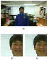
도 5a에는 검출 알고리즘에 의해 검출된 얼굴 영역에 대한 관심 영역과 탐색 윈도우가 도시되어 있다. 얼굴 영역을 검출하기 위한 검출 알고리즘은 다양할 수 있으나, 일 예로서 P. Viola 및 M. Jones의 논문 "Robust real-time face detection,"에서 제시한 검출 알고리즘을 설명하면 우선, Haar-like 특징 패턴으로부터 복수의 약 분류기(weak classifier)가 생성되고 복수의 약 분류기들은 Adaboost 알고리즘에 의해 강 분류기를 이루며, 강 분류기 (strong classifier)로 구성된 케스케이드 구조에 의해 얼굴인지 아닌지 구분된다.5A shows a region of interest and a search window for a face region detected by a detection algorithm. The detection algorithm for detecting the face region may vary, but as an example, the detection algorithm presented in the paper "Robust real-time face detection," by P. Viola and M. Jones, will be described first. A plurality of weak classifiers are generated from the plurality of weak classifiers, and the plurality of weak classifiers form a strong classifier by the Adaboost algorithm, and are classified as a face or not by a cascade structure composed of strong classifiers.
적절한 파라미터 Do와 k를 선택하기 위해서 빠른 움직임을 촬영한 실험 영상 2를 사용하였다. 실험 영상 2는 사람의 얼굴을 ROI로 설정하고, 사람이 카메라를 향해 가까이 왔다가 다시 멀어지는 두 번의 상황을 빠른 속도의 움직임으로 촬영한 영상이다. 사람이 카메라를 향해 달려오다가 서서히 속도를 낮추면서 결국 470번째 프레임에 가까워 질수록 멈추고, 잠시 카메라 앞에 멈춘 후 다시 뒷걸음으로 점점 빨리 카메라로부터 멀어지는 상황을 연출했다. 이 때, 추출된 디스패리티 값들의 차이값에 대한 절대값 크기는 움직이는 물체의 속도가 정지하기 위해 느려졌다가 다시 빨라지기 때문에 470번째 프레임에 가까워 질수록 점점 작아지고, 잠시 0(zero)이었다가 가지다가 그 이후에는 점점 커지는 양상을 보인다.
우선, n번째의 탐색 범위 Dn이 고정된 값인 오프셋(Do)만이 아닌 디스패리티의 추세에 적응적으로 변화되는
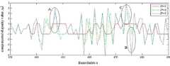
도 5b는 Dn과 Do가 일치하는 경우, Do의 변화에 따른 430번째 프레임부터 490번째 프레임까지의 디스패리티 보상값(
즉, 도 5b의 타원 A를 보면 Do=1일 때

도 5c를 참조하면, 좁은 탐색 범위로부터 발생한 클리핑으로부터 잘못된 보상값이 산출되어 디스패리티를 잘못 추정하게 만드는 실험 결과가 확인된다. 참고로, 도 5c는 447번째 프레임에 대한 Do의 변화에 따른 결과 영상에 대한 것으로, (a)는 검증자료(ground truth)를 이용한 결과이고, (b)는 Do=1일 때의

도 5c의 (c)에서는 클리핑되지 않아 얼굴 영역에서 좌, 우 영상이 제대로 겹쳐지는 것을 볼 수 있지만, 그림 5c의 (b)에서는 클리핑되어 얼굴 영역에서 좌, 우 영상이 제대로 겹쳐지지 않는 것을 확인할 수 있으며, 이는 도 5c의 (b)에서는 탐색범위가 매우 작아 잘못된 보상값이 산출되어 결국 디스패리티가 부적절하게 추정되었기 때문이다. 그러나, 이러한 문제점을 해소하기 위해, 탐색 범위가 매우 클 필요는 없으며, 도 5b의 타원 B에 도시된 바와 같이 Do=3일 때

도 5d는 476번째 프레임에 대한 오프셋(Do)의 변화에 따른 결과 영상에 대한 것으로, (a)는 검증자료(ground truth)를 이용한 결과이고, (b)는 (a)의 사각형 위치만큼 Do=3일 때의 결과를 확대한 영상이고, (c)는 (a)의 사각형 위치만큼 Do=5일 때의 결과를 확대한 영상이다.FIG. 5D illustrates the resultant image according to the change of the offset Do for the 476th frame, (a) is the result using ground truth, and (b) is the D as the rectangular position of (a).The image when the result ofo = 3 is enlarged, and (c) is the image which enlarged the result when Do = 5 by the rectangular position of (a).
적당한 탐색 범위가 적용된 도 5d의 (b)에서는 얼굴 영역에서 좌, 우 영상이 겹쳐지는 것을 볼 수 있지만, 도 5d의 (c)에서는 넓은 탐색 범위로 인해 발생된 에러 때문에 얼굴 영역에서 좌, 우 영상이 제대로 겹쳐지지 않음을 확인할 수 있다.In FIG. 5D (b) to which an appropriate search range is applied, the left and right images are overlapped in the face area. However, in FIG. 5D (c), the left and right images are in the face area due to an error caused by a wide search range. You can see that this doesn't overlap properly.
하기 표 1은 탐색 범위의 오프셋에 따른 ERMS에 대한 결과를 비교한 것이다.Table 1 below compares the results for the ERMS according to the offset of the search range.
위 표1에서 보이는 바와 같이, Do=3에서 가장 낮은 ERMS 값을 나타내는데, 이는 Do=3을 사용하여 디스패리티를 추정했을 때 가장 검증자료와 가깝다는 것을 의미한다. Do=5일 때 클리핑 영역이 가장 나타나지 않지만 ERMS가 Do=3일 때의 ERMS보다 낮지 않은 이유는 도 5b에서의 타원 B와 같이 넓은 탐색 범위 때문에 발생하는 잘못 추정된 디스패리티때문이다.As seen from the above Table 1, represent the lowestRMS value E at Do = 3, this means that the closest and the verification data when estimating the disparity using the Do = 3. The clipping region does not appear most when Do = 5, but the ERMS is not lower than ERMS when Do = 3 because of an incorrectly estimated disparity caused by a wider search range, such as ellipse B in FIG. 5B. .
하지만 항상 잘못된 디스패리티를 추정하는 것은 아니며, 도 5b에서 474번째 프레임 근처의 타원 C와 같이 일부 영역에서는 Do=3일 때 보다 검증자료와 가까운 디스패리티를 추정하기도 한다. Do =1일 때 큰 값의 ERMS를 나타내는 이유는 앞 프레임에서부터 매우 좁은 탐색 범위로부터 제대로 디스패리티가 추정되지 않고, 그 이후에도 계속 잘못된 디스패리티만을 추정하였기 때문이다.However, incorrect disparity is not always estimated, and in some areas, such as ellipse C near the 474th frame in FIG. 5B, disparity closer to verification data may be estimated than when Do = 3. The reason why a large value of ERMS is shown whenDO = 1 is that disparity is not properly estimated from a very narrow search range from the previous frame, and only wrong disparity is estimated after that.
도 5d와 표 1을 참조하여 앞서 설명한 사항들을 고려할 때, 추정된 인접한 디스패리티들의 차이가 큰 구간에서는 탐색 범위를 넓힐 필요가 있고, 추정된 인접한 디스패리티들의 차이가 크지 않은 구간에서는 탐색 범위를 좁힐 필요성이 야기된다.Considering the foregoing descriptions with reference to FIG. 5D and Table 1, it is necessary to widen the search range in a section where the estimated differences of the disparities are large, and narrow the search range in a section where the estimated differences of the disparities are not large. A need arises.
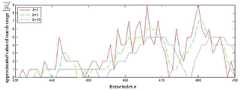
도 5e는 인접한 디스패리티들의 개수 k의 변화에 따른 430번째 프레임에서 490번째 프레임의 탐색범위의 보정값
추정된 디스패리티들의 차이에 대한 k개의 평균값들로 이루어진
다만, 전반적인 그래프에서 결과에 큰 영향을 주지 않는 무시할 수 있는 2프레임 정도의 지연이 발생되고 있다. k=10일 때의 결과에서는 k=3일 때의 결과보다 더 완화되어 잡음이라고 여겨지는 부분이 모두 없어진 것을 볼 수 있으나, 결과에 큰 영향을 주는 무시할 수 없는 5프레임 정도의 지연이 발생됨을 확인할 수 있다.However, there is a negligible two-frame delay that does not significantly affect the results in the overall graph. In the result of k = 10, we can see that all the parts considered to be noise are removed more than the result of k = 3, but we can see that there is a negligible 5 frame delay that greatly affects the result. Can be.
하기 표 2는 오프셋을 3으로 고정하고 n-k부터 n번째 프레임까지의 인접한 k개 디스패리티들의 차이에 따른 RMS에 대한 결과를 비교한 것이다.
Table 2 below compares the results for RMS by fixing the offset to 3 and the difference between the adjacent k disparities from nk to nth frame.
표 2를 참조하면, k가 3에 가까워질수록 ERMS의 값이 점점 작아지다가 3보다 커질 경우 그래프의 지연 때문에 적응적인 탐색 범위의 크기가 잘못 적용되어 ERMS가 커지는 것을 볼 수 있다.Referring to Table 2, it can be seen that as k approaches 3, the value of ERMS decreases gradually, and when it exceeds 3, the value of the adaptive search range is incorrectly applied due to the delay of the graph, thereby increasing the ERMS .
도 5f는 예시된 다섯가지 실험 영상에 대해 좌측부터 차례대로 Chen의 방법(W.-C. Chen, F.-J. Hsiao, and C.-W. Lin, “An automatic parallax adjustment method for stereoscopic augmented reality systems,” in Proc. Int. Symposium on 2010 9th Mixed and Augmented Reality, pp. 215-216, Seoul, Korea, Oct. 2010.), Xu의 방법(D. Xu, L. E. Corea, and P. Nasiopoulos, “Quality of experience for the horizontal pixel parallax,” in Proc. 2012 Digest of Technical Papers Int. Conf. Consumer Electronics, pp. 394-395, Las Vegas, NV, Jan. 2012.) 및 본 실시예에 따른 방법에 대한 결과 영상을 나타낸다. 또한, 표 3은 도 5f에서의 결과에 적용된 추정된 디스패리티 값을 나타내고, 괄호 속의 값은 제안하는 방법에서 추정된 디스패리티 값과의 차이를 나타낸다.
5F shows Chen's method (W.-C. Chen, F.-J. Hsiao, and C.-W. Lin, “An automatic parallax adjustment method for stereoscopic augmented) from left to right for the five experimental images illustrated. reality systems, ”in Proc. Int. Symposium on 2010 9th Mixed and Augmented Reality, pp. 215-216, Seoul, Korea, Oct. 2010.), the method of Xu (D. Xu, LE Corea, and P. Nasiopoulos, “Quality of experience for the horizontal pixel parallax,” in Proc. 2012 Digest of Technical Papers Int. Conf.Consumer Electronics, pp. 394-395, Las Vegas, NV, Jan. 2012.) and the method according to this embodiment. The resulting image is shown. In addition, Table 3 shows the estimated disparity value applied to the result in FIG. 5F, and the values in parentheses show the difference from the estimated disparity value in the proposed method.
도 5f의 (a)를 참조하면, 본 실시예의 경우 추정된 디스패리티 86만큼 이동한 결과 관심 영역에 수렴점이 맞춰짐을 확인할 수 있으나, Chen이나 Xu 등의 방법을 적용하는 경우 각각 44 또는 101이라는 디스패리티가 적용되어 본 실시예와 비교할 때 각각 -42 또는 15라는 큰 음시차 또는 작은 양시차를 가지기 때문에 좌우 영상이 제대로 겹쳐지지 않음을 확인할 수 있다.Referring to (a) of FIG. 5F, in the present exemplary embodiment, the convergence point is adjusted to the region of interest as a result of moving by the estimated disparity 86. However, when the method of Chen or Xu is applied, the disc is 44 or 101, respectively. When the parity is applied, it has a large disparity or a small positive disparity of -42 or 15, respectively, compared to the present embodiment, so that the left and right images do not overlap properly.
또한 이러한 결과가 실험 영상 (b) 내지 (e)에서 공통됨을 확인할 수 있다. 이는 본 실시예의 경우 Chen이나 Xu의 방법과 달리 매 프레임마다 관심 영역의 디스패리티를 개별적으로 추정하여 그 프레임마다 추정된 디스패리티를 적용하기 때문이다. 다만 실험 영상 (d)의 경우 영상에 세개의 물체 A, B 및 C가 존재하며, 수렴점은 물체 A에 맞춰진 상태이며, 물체 B와 C는 각각 양시차 또는 음시차를 가지는 물체이므로 3차원 공간상에서 디스플레이 장치보다 앞 또는 뒤에 위치함을 확인할 수 있다.In addition, it can be confirmed that these results are common in the experimental images (b) to (e). This is because, in the present embodiment, unlike the method of Chen or Xu, the disparity of the ROI is individually estimated for each frame and the estimated disparity is applied to each frame. However, in the case of the experimental image (d), three objects A, B, and C exist in the image, the convergence point is set to the object A, and the objects B and C are objects having positive or negative parallax, respectively, so that they are three-dimensional space. It can be seen that it is located in front of or behind the display device.
이와 같이, 본 실시예는 매 프레임마다 관심 영역의 디스패리티를 개별적으로 추정하여 그 프레임마다 추정된 디스패리티를 적용함으로써 좌우 영상의 관심 영역이 수렴점(즉, 매 프레임에서 디스패리티가 0(zero))에 맞춰질 수 있으며, 이를 통해 다른 종래의 방법들에 비해 눈의 피로도(visual fatigue)를 감소시킬 수 있고 눈의 편안함(visual comfort)를 증진시킬 수 있으며, 또한 주위 물체들의 상대적인 디스패리티 변화 때문에 3차원 효과도 더욱 느낄 수 있도록 하는 장점이 있다.
As described above, according to the present exemplary embodiment, the disparity of the ROI is individually estimated for each frame, and the disparity of the left and right images is converged (ie, the disparity is zero in every frame). ), Which can reduce visual fatigue, enhance visual comfort of the eye compared to other conventional methods, and also due to the relative disparity change of the surrounding objects. The three-dimensional effect also has the advantage that you can feel more.
상술한 디스패리티 추정 방법은 디지털 처리 장치에 내장되거나 설치된 프로그램 등에 의해 시계열적 순서에 따른 자동화된 절차로 수행될 수도 있음은 당연하다. 상기 프로그램을 구성하는 코드들 및 코드 세그먼트들은 당해 분야의 컴퓨터 프로그래머에 의하여 용이하게 추론될 수 있다. 또한, 상기 프로그램은 디지털 처리 장치가 읽을 수 있는 정보저장매체(computer readable media)에 저장되고, 디지털 처리 장치에 의하여 읽혀지고 실행됨으로써 상기 방법을 구현한다. 상기 정보저장매체는 자기 기록매체, 광 기록매체 및 캐리어 웨이브 매체를 포함한다.
Naturally, the above-described disparity estimation method may be performed by an automated procedure in a time series order by a program embedded in or installed in a digital processing apparatus. The codes and code segments that make up the program can be easily deduced by a computer programmer in the field. In addition, the program is stored in a computer readable medium readable by the digital processing apparatus, and is read and executed by the digital processing apparatus to implement the method. The information storage medium includes a magnetic recording medium, an optical recording medium, and a carrier wave medium.
상기에서는 본 발명의 실시예를 참조하여 설명하였지만, 해당 기술 분야에서 통상의 지식을 가진 자라면 하기의 특허 청구의 범위에 기재된 본 발명의 사상 및 영역으로부터 벗어나지 않는 범위 내에서 본 발명을 다양하게 수정 및 변경시킬 수 있음을 이해할 수 있을 것이다.
It will be apparent to those skilled in the art that various modifications and variations can be made in the present invention without departing from the spirit or scope of the invention as defined in the following claims And changes may be made without departing from the spirit and scope of the invention.
210 : ROI 입력부
220 : 탐색 윈도우 결정부
225 : 디스패리티 근사화 유닛
230 : 디스패리티 추정부
240 : 적응적 탐색 범위 결정부210: ROI input unit
220: search window determination unit
225 disparity approximation unit
230: disparity estimation unit
240: adaptive search range determination unit
Claims (17)
Translated fromKorean입력된 관심 영역(ROI)의 좌표 정보를 이용하여 디스패리티(disparity) 추정을 위한 탐색 윈도우를 결정하는 탐색 윈도우 결정부; 및
상기 결정된 탐색 윈도우 및 동영상의 템포럴(temporal) 정보를 이용하여 각 프레임별로 탐색 범위 결정 및 디스패리티 값 추정을 수행하는 디스패리티 근사화 유닛을 포함하는 디스패리티 추정 장치.
A disparity estimation apparatus using adaptive search range prediction for auto convergence,
A search window determiner configured to determine a search window for disparity estimation using the input coordinate information of the ROI; And
And a disparity approximation unit configured to determine a search range and estimate a disparity value for each frame by using the determined search window and temporal information of the video.
상기 템포럴 정보는 시간적으로 앞선 프레임에 대해 추정된 디스패리티 값인 것을 특징으로 하는 디스패리티 추정 장치.
The method of claim 1,
And the temporal information is a disparity value estimated for a temporally preceding frame.
상기 탐색 윈도우는 하기 수학식

에 의해 결정되되,


The method of claim 1,
The search window is represented by the following equation
Determined by
각 프레임별로 개별 결정되는 상기 디스패리티 값 중 n번째 프레임의 디스패리티 값(


상기


The method of claim 1,
The disparity value of the nth frame among the disparity values individually determined for each frame (
remind
n번째 프레임의 상기 디스패리티 근사값(


상기

5. The method of claim 4,
The disparity approximation value of the nth frame (
remind
n번째 프레임의 상기 디스패리티 보상값(


에 의해 산출되되,
IL과 IR은 2차원 평면으로 투사된 좌측 및 우측 2차원 영상이고, (p, q)는 탐색 윈도우 내의 픽셀의 좌표이며, N은 동영상의 총 프레임 수이고, Dn은 산출된 탐색 범위의 값인 것을 특징으로 하는 디스패리티 추정 장치.
5. The method of claim 4,
the disparity compensation value of the nth frame (
Calculated by
IL and IR are left and right two-dimensional images projected in a two-dimensional plane, (p, q) are the coordinates of the pixels in the search window, N is the total number of frames in the video, and Dn is the calculated search range Disparity estimation apparatus, characterized in that the value of.
각 프레임별로 개별 결정되는 상기 탐색 범위의 값(Dn)은 하기 수학식

에 의해 결정되되,
상기 D0는 미리 지정된 오프셋(offset)이고, 상기


The method according to claim 6,
The value Dn of the search range individually determined for each frame is represented by the following equation.
Determined by
D0 is a predetermined offset, and
상기 k는 3인 것을 특징으로 하는 디스패리티 추정 장치.
The method of claim 7, wherein
K is 3;
입력된 관심 영역(ROI)의 좌표 정보를 이용하여 디스패리티(disparity) 추정을 위한 탐색 윈도우를 결정하는 단계; 및
상기 결정된 탐색 윈도우 및 동영상의 템포럴(temporal) 정보를 이용하여 각 프레임별로 탐색 범위 결정 및 디스패리티 값 추정을 수행하는 단계를 포함하는 디스패리티 추정 방법.
A disparity estimation method using adaptive search range prediction for auto convergence, which is performed by a disparity estimating apparatus,
Determining a search window for disparity estimation using the input coordinate information of the ROI; And
And performing search range determination and disparity value estimation for each frame by using the determined search window and temporal information of the video.
상기 템포럴 정보는 시간적으로 앞선 프레임에 대해 추정된 디스패리티 값인 것을 특징으로 하는 디스패리티 추정 방법.
10. The method of claim 9,
And the temporal information is a disparity value estimated for a temporally preceding frame.
상기 탐색 윈도우는 하기 수학식

에 의해 결정되되,


10. The method of claim 9,
The search window is represented by the following equation
Determined by
각 프레임별로 개별 결정되는 상기 디스패리티 값 중 n번째 프레임의 디스패리티 값(


상기


10. The method of claim 9,
The disparity value of the nth frame among the disparity values individually determined for each frame (
remind
n번째 프레임의 상기 디스패리티 근사값(


상기

The method of claim 12,
The disparity approximation value of the nth frame (
remind
n번째 프레임의 상기 디스패리티 보상값(


에 의해 산출되되,
IL과 IR은 2차원 평면으로 투사된 좌측 및 우측 2차원 영상이고, (p, q)는 탐색 윈도우 내의 픽셀의 좌표이며, N은 동영상의 총 프레임 수이고, Dn은 산출된 탐색 범위의 값인 것을 특징으로 하는 디스패리티 추정 방법.
The method of claim 12,
the disparity compensation value of the nth frame (
Calculated by
IL and IR are left and right two-dimensional images projected in a two-dimensional plane, (p, q) are the coordinates of the pixels in the search window, N is the total number of frames in the video, and Dn is the calculated search range Disparity estimation method characterized in that the value of.
각 프레임별로 개별 결정되는 상기 탐색 범위의 값(Dn)은 하기 수학식

에 의해 결정되되,
상기 D0는 미리 지정된 오프셋(offset)이고, 상기


15. The method of claim 14,
The value Dn of the search range individually determined for each frame is represented by the following equation.
Determined by
D0 is a predetermined offset, and
상기 k는 3인 것을 특징으로 하는 디스패리티 추정 방법.
16. The method of claim 15,
K is 3;
Priority Applications (1)
| Application Number | Priority Date | Filing Date | Title |
|---|---|---|---|
| KR1020120123131AKR101340086B1 (en) | 2012-11-01 | 2012-11-01 | Disparity estimation method and device for auto convergence using adaptive search range prediction in video |
Applications Claiming Priority (1)
| Application Number | Priority Date | Filing Date | Title |
|---|---|---|---|
| KR1020120123131AKR101340086B1 (en) | 2012-11-01 | 2012-11-01 | Disparity estimation method and device for auto convergence using adaptive search range prediction in video |
Publications (1)
| Publication Number | Publication Date |
|---|---|
| KR101340086B1true KR101340086B1 (en) | 2013-12-09 |
Family
ID=49988015
Family Applications (1)
| Application Number | Title | Priority Date | Filing Date |
|---|---|---|---|
| KR1020120123131AExpired - Fee RelatedKR101340086B1 (en) | 2012-11-01 | 2012-11-01 | Disparity estimation method and device for auto convergence using adaptive search range prediction in video |
Country Status (1)
| Country | Link |
|---|---|
| KR (1) | KR101340086B1 (en) |
Cited By (3)
| Publication number | Priority date | Publication date | Assignee | Title |
|---|---|---|---|---|
| KR101480075B1 (en) | 2013-06-20 | 2015-01-09 | (주)베라시스 | Adaptive Object Search Method By Considering Distance |
| CN113132737A (en)* | 2021-04-21 | 2021-07-16 | 北京邮电大学 | Video prediction method based on Taylor decoupling and memory unit correction |
| CN114842061A (en)* | 2021-02-02 | 2022-08-02 | 瑞芯微电子股份有限公司 | Depth computing method, system, readable storage medium and depth image processing device |
Citations (3)
| Publication number | Priority date | Publication date | Assignee | Title |
|---|---|---|---|---|
| KR20090090148A (en)* | 2008-02-20 | 2009-08-25 | 삼성전자주식회사 | Method and apparatus for determining view positions of stereoscopic images for stereo synchronization |
| KR20120017658A (en)* | 2010-08-19 | 2012-02-29 | 주식회사 이시티 | Method and apparatus for processing stereoscopic image signal for vergence control |
| KR20120042323A (en)* | 2010-10-25 | 2012-05-03 | 삼성전자주식회사 | Method and apparatus for temporally-consistent disparity estimation using texture and motion detection |
- 2012
- 2012-11-01KRKR1020120123131Apatent/KR101340086B1/ennot_activeExpired - Fee Related
Patent Citations (3)
| Publication number | Priority date | Publication date | Assignee | Title |
|---|---|---|---|---|
| KR20090090148A (en)* | 2008-02-20 | 2009-08-25 | 삼성전자주식회사 | Method and apparatus for determining view positions of stereoscopic images for stereo synchronization |
| KR20120017658A (en)* | 2010-08-19 | 2012-02-29 | 주식회사 이시티 | Method and apparatus for processing stereoscopic image signal for vergence control |
| KR20120042323A (en)* | 2010-10-25 | 2012-05-03 | 삼성전자주식회사 | Method and apparatus for temporally-consistent disparity estimation using texture and motion detection |
Cited By (4)
| Publication number | Priority date | Publication date | Assignee | Title |
|---|---|---|---|---|
| KR101480075B1 (en) | 2013-06-20 | 2015-01-09 | (주)베라시스 | Adaptive Object Search Method By Considering Distance |
| CN114842061A (en)* | 2021-02-02 | 2022-08-02 | 瑞芯微电子股份有限公司 | Depth computing method, system, readable storage medium and depth image processing device |
| CN114842061B (en)* | 2021-02-02 | 2025-06-03 | 瑞芯微电子股份有限公司 | Depth calculation method, system, readable storage medium and depth image processing device |
| CN113132737A (en)* | 2021-04-21 | 2021-07-16 | 北京邮电大学 | Video prediction method based on Taylor decoupling and memory unit correction |
Similar Documents
| Publication | Publication Date | Title |
|---|---|---|
| EP3395064B1 (en) | Processing a depth map for an image | |
| US9898080B2 (en) | Method and apparatus for eye tracking | |
| CA2668941C (en) | System and method for model fitting and registration of objects for 2d-to-3d conversion | |
| US10070115B2 (en) | Methods for full parallax compressed light field synthesis utilizing depth information | |
| US9204128B2 (en) | Stereoscopic shooting device | |
| KR101038402B1 (en) | Real-time capture and generation of stereo images and video by monoscopic low power mobile devices | |
| US9426447B2 (en) | Apparatus and method for eye tracking | |
| JP5153940B2 (en) | System and method for image depth extraction using motion compensation | |
| CA2723627C (en) | System and method for measuring potential eyestrain of stereoscopic motion pictures | |
| EP2291825B1 (en) | System and method for depth extraction of images with forward and backward depth prediction | |
| US20110228051A1 (en) | Stereoscopic Viewing Comfort Through Gaze Estimation | |
| CN110245549B (en) | Real-time face and object manipulation | |
| RU2423018C2 (en) | Method and system to convert stereo content | |
| KR101769177B1 (en) | Apparatus and method for eye tracking | |
| JP5015126B2 (en) | Image generation method, image authentication method, image generation apparatus, image authentication apparatus, program, and recording medium | |
| US20120320152A1 (en) | Stereoscopic image generation apparatus and method | |
| US20140002612A1 (en) | Stereoscopic shooting device | |
| US8982187B2 (en) | System and method of rendering stereoscopic images | |
| CA2704479A1 (en) | System and method for depth map extraction using region-based filtering | |
| EP3311361A1 (en) | Method and apparatus for determining a depth map for an image | |
| EP4381739B1 (en) | Coding hybrid multi-view sensor configurations | |
| KR101340086B1 (en) | Disparity estimation method and device for auto convergence using adaptive search range prediction in video | |
| US12206830B2 (en) | Techniques for displaying and capturing images | |
| JP6685241B2 (en) | Stereoscopic video generation | |
| KR101629414B1 (en) | Method of image extraction based on human factors and apparatus thereof |
Legal Events
| Date | Code | Title | Description |
|---|---|---|---|
| A201 | Request for examination | ||
| PA0109 | Patent application | St.27 status event code:A-0-1-A10-A12-nap-PA0109 | |
| PA0201 | Request for examination | St.27 status event code:A-1-2-D10-D11-exm-PA0201 | |
| D13-X000 | Search requested | St.27 status event code:A-1-2-D10-D13-srh-X000 | |
| D14-X000 | Search report completed | St.27 status event code:A-1-2-D10-D14-srh-X000 | |
| E701 | Decision to grant or registration of patent right | ||
| PE0701 | Decision of registration | St.27 status event code:A-1-2-D10-D22-exm-PE0701 | |
| GRNT | Written decision to grant | ||
| PR0701 | Registration of establishment | St.27 status event code:A-2-4-F10-F11-exm-PR0701 | |
| PR1002 | Payment of registration fee | St.27 status event code:A-2-2-U10-U11-oth-PR1002 Fee payment year number:1 | |
| PG1601 | Publication of registration | St.27 status event code:A-4-4-Q10-Q13-nap-PG1601 | |
| P22-X000 | Classification modified | St.27 status event code:A-4-4-P10-P22-nap-X000 | |
| PR1001 | Payment of annual fee | St.27 status event code:A-4-4-U10-U11-oth-PR1001 Fee payment year number:4 | |
| R18-X000 | Changes to party contact information recorded | St.27 status event code:A-5-5-R10-R18-oth-X000 | |
| P22-X000 | Classification modified | St.27 status event code:A-4-4-P10-P22-nap-X000 | |
| FPAY | Annual fee payment | Payment date:20171128 Year of fee payment:5 | |
| PR1001 | Payment of annual fee | St.27 status event code:A-4-4-U10-U11-oth-PR1001 Fee payment year number:5 | |
| FPAY | Annual fee payment | Payment date:20181126 Year of fee payment:6 | |
| PR1001 | Payment of annual fee | St.27 status event code:A-4-4-U10-U11-oth-PR1001 Fee payment year number:6 | |
| PN2301 | Change of applicant | St.27 status event code:A-5-5-R10-R13-asn-PN2301 St.27 status event code:A-5-5-R10-R11-asn-PN2301 | |
| R18-X000 | Changes to party contact information recorded | St.27 status event code:A-5-5-R10-R18-oth-X000 | |
| PC1903 | Unpaid annual fee | St.27 status event code:A-4-4-U10-U13-oth-PC1903 Not in force date:20191204 Payment event data comment text:Termination Category : DEFAULT_OF_REGISTRATION_FEE | |
| PC1903 | Unpaid annual fee | St.27 status event code:N-4-6-H10-H13-oth-PC1903 Ip right cessation event data comment text:Termination Category : DEFAULT_OF_REGISTRATION_FEE Not in force date:20191204 | |
| R18-X000 | Changes to party contact information recorded | St.27 status event code:A-5-5-R10-R18-oth-X000 | |
| PN2301 | Change of applicant | St.27 status event code:A-5-5-R10-R13-asn-PN2301 St.27 status event code:A-5-5-R10-R11-asn-PN2301 | |
| R18-X000 | Changes to party contact information recorded | St.27 status event code:A-5-5-R10-R18-oth-X000 | |
| R18-X000 | Changes to party contact information recorded | St.27 status event code:A-5-5-R10-R18-oth-X000 | |
| R18-X000 | Changes to party contact information recorded | St.27 status event code:A-5-5-R10-R18-oth-X000 | |
| R18-X000 | Changes to party contact information recorded | St.27 status event code:A-5-5-R10-R18-oth-X000 |