KR101338459B1 - Sensor unit - Google Patents
Sensor unitDownload PDFInfo
- Publication number
- KR101338459B1 KR101338459B1KR1020120116825AKR20120116825AKR101338459B1KR 101338459 B1KR101338459 B1KR 101338459B1KR 1020120116825 AKR1020120116825 AKR 1020120116825AKR 20120116825 AKR20120116825 AKR 20120116825AKR 101338459 B1KR101338459 B1KR 101338459B1
- Authority
- KR
- South Korea
- Prior art keywords
- elastic member
- sensor unit
- unit
- infrared
- receiving
- Prior art date
- Legal status (The legal status is an assumption and is not a legal conclusion. Google has not performed a legal analysis and makes no representation as to the accuracy of the status listed.)
- Active
Links
Images


Classifications
- G—PHYSICS
- G08—SIGNALLING
- G08B—SIGNALLING OR CALLING SYSTEMS; ORDER TELEGRAPHS; ALARM SYSTEMS
- G08B13/00—Burglar, theft or intruder alarms
- G08B13/18—Actuation by interference with heat, light, or radiation of shorter wavelength; Actuation by intruding sources of heat, light, or radiation of shorter wavelength
- G08B13/181—Actuation by interference with heat, light, or radiation of shorter wavelength; Actuation by intruding sources of heat, light, or radiation of shorter wavelength using active radiation detection systems
- B—PERFORMING OPERATIONS; TRANSPORTING
- B60—VEHICLES IN GENERAL
- B60R—VEHICLES, VEHICLE FITTINGS, OR VEHICLE PARTS, NOT OTHERWISE PROVIDED FOR
- B60R16/00—Electric or fluid circuits specially adapted for vehicles and not otherwise provided for; Arrangement of elements of electric or fluid circuits specially adapted for vehicles and not otherwise provided for
- B60R16/02—Electric or fluid circuits specially adapted for vehicles and not otherwise provided for; Arrangement of elements of electric or fluid circuits specially adapted for vehicles and not otherwise provided for electric constitutive elements
- B60R16/023—Electric or fluid circuits specially adapted for vehicles and not otherwise provided for; Arrangement of elements of electric or fluid circuits specially adapted for vehicles and not otherwise provided for electric constitutive elements for transmission of signals between vehicle parts or subsystems
- B—PERFORMING OPERATIONS; TRANSPORTING
- B60—VEHICLES IN GENERAL
- B60R—VEHICLES, VEHICLE FITTINGS, OR VEHICLE PARTS, NOT OTHERWISE PROVIDED FOR
- B60R25/00—Fittings or systems for preventing or indicating unauthorised use or theft of vehicles
- B60R25/10—Fittings or systems for preventing or indicating unauthorised use or theft of vehicles actuating a signalling device
- G—PHYSICS
- G01—MEASURING; TESTING
- G01J—MEASUREMENT OF INTENSITY, VELOCITY, SPECTRAL CONTENT, POLARISATION, PHASE OR PULSE CHARACTERISTICS OF INFRARED, VISIBLE OR ULTRAVIOLET LIGHT; COLORIMETRY; RADIATION PYROMETRY
- G01J5/00—Radiation pyrometry, e.g. infrared or optical thermometry
- G01J5/02—Constructional details
- B—PERFORMING OPERATIONS; TRANSPORTING
- B60—VEHICLES IN GENERAL
- B60R—VEHICLES, VEHICLE FITTINGS, OR VEHICLE PARTS, NOT OTHERWISE PROVIDED FOR
- B60R21/00—Arrangements or fittings on vehicles for protecting or preventing injuries to occupants or pedestrians in case of accidents or other traffic risks
- B60R21/01—Electrical circuits for triggering passive safety arrangements, e.g. airbags, safety belt tighteners, in case of vehicle accidents or impending vehicle accidents
- B60R21/013—Electrical circuits for triggering passive safety arrangements, e.g. airbags, safety belt tighteners, in case of vehicle accidents or impending vehicle accidents including means for detecting collisions, impending collisions or roll-over
- B60R21/0134—Electrical circuits for triggering passive safety arrangements, e.g. airbags, safety belt tighteners, in case of vehicle accidents or impending vehicle accidents including means for detecting collisions, impending collisions or roll-over responsive to imminent contact with an obstacle, e.g. using radar systems
- B—PERFORMING OPERATIONS; TRANSPORTING
- B60—VEHICLES IN GENERAL
- B60R—VEHICLES, VEHICLE FITTINGS, OR VEHICLE PARTS, NOT OTHERWISE PROVIDED FOR
- B60R21/00—Arrangements or fittings on vehicles for protecting or preventing injuries to occupants or pedestrians in case of accidents or other traffic risks
- B60R21/01—Electrical circuits for triggering passive safety arrangements, e.g. airbags, safety belt tighteners, in case of vehicle accidents or impending vehicle accidents
- B60R21/013—Electrical circuits for triggering passive safety arrangements, e.g. airbags, safety belt tighteners, in case of vehicle accidents or impending vehicle accidents including means for detecting collisions, impending collisions or roll-over
- B60R21/0136—Electrical circuits for triggering passive safety arrangements, e.g. airbags, safety belt tighteners, in case of vehicle accidents or impending vehicle accidents including means for detecting collisions, impending collisions or roll-over responsive to actual contact with an obstacle, e.g. to vehicle deformation, bumper displacement or bumper velocity relative to the vehicle
- G—PHYSICS
- G01—MEASURING; TESTING
- G01P—MEASURING LINEAR OR ANGULAR SPEED, ACCELERATION, DECELERATION, OR SHOCK; INDICATING PRESENCE, ABSENCE, OR DIRECTION, OF MOVEMENT
- G01P15/00—Measuring acceleration; Measuring deceleration; Measuring shock, i.e. sudden change of acceleration
Landscapes
- Physics & Mathematics (AREA)
- General Physics & Mathematics (AREA)
- Spectroscopy & Molecular Physics (AREA)
- Engineering & Computer Science (AREA)
- Mechanical Engineering (AREA)
- Burglar Alarm Systems (AREA)
- Geophysics And Detection Of Objects (AREA)
- Traffic Control Systems (AREA)
Abstract
Description
Translated fromKorean본 발명은 일정한 주파수의 파장(예들 들어, 적외선: IR: infra-red)을 발산하는 송신부와 반사되어 돌아오는 파장을 수신하는 수신부를 이용하여 외부 침입을 감지하고, 동시에 외부충격이나 진동을 감지할 수 있는 센서유닛에 관한 것이다.The present invention detects an external intrusion by using a transmitter that emits a wavelength of a constant frequency (for example, infrared (IR) infra-red) and a receiver that receives a reflected wavelength, and simultaneously detects external shock or vibration. It relates to a sensor unit that can be.
일반적으로, 충격감지센서는 가속도센서를 이용하여 충격에 의해서 발생되는 속도의 변화를 감지하고 경보기가 작동하도록 한다.In general, the shock sensor uses an acceleration sensor to detect a change in speed caused by the impact and to activate the alarm.
이러한 가속도센서를 사용함으로써 임의 방향의 충격은 용이하게 감지할 수 있으나, 충격을 주지 않으면서 차량을 훼손하거나 침입하는 것을 방지하기 힘들고, 지면과 수평하게 설치되어야 하는 제약도 있다.By using such an acceleration sensor, shock in any direction can be easily detected, but it is difficult to prevent damage or invasion of the vehicle without giving an impact, and there is a restriction to be installed horizontally with the ground.
또한, 차량용 실내침입 감지장치는 초음파센서를 이용하여 차량 내부에 초음파를 발산하는데, 내부 침입을 감지하도록 반사되는 초음파를 이용하여 작동한다.In addition, the indoor intrusion detection apparatus for a vehicle emits ultrasonic waves inside the vehicle by using an ultrasonic sensor, and operates using ultrasonic waves reflected to detect internal intrusion.
그러나, 초음파센서를 이용하기 때문에 소비전력이 비교적 높고 가격이 비싼 단점이 있으며, 차량 내부만 감지하기 때문에 외부에서 충격만 주고 침입하지 않는 경우에는 작동하지 않을 수 있다.However, there is a disadvantage that the power consumption is relatively high and expensive because the ultrasonic sensor is used, and since only the inside of the vehicle is sensed, it may not work when only the impact is applied from the outside.
따라서, 본 발명의 목적은 실내침입을 감지하고, 동시에 충격을 감지할 수 있으며, 실내와 실외를 포함하여 다양한 위치에 설치될 수 있고, 간단한 구조로 비용이 절감되고 소비전력이 비교적 낮은 센서유닛을 제공하는 것이다.Accordingly, an object of the present invention is to detect a room intrusion, and at the same time can detect a shock, can be installed in a variety of locations, including indoors and outdoors, and a simple structure to reduce the cost and relatively low power consumption sensor unit To provide.
본 발명의 실시예에 따른 센서유닛은, 일측에 고정되는 고정부, 그 일단이 상기 고정부의 외측에 고정되는 탄성부재, 상기 탄성부재의 타단에 장착되어 적외선을 발산하는 송신부, 임의의 물체로부터 반사된 적외선을 수신하는 수신부, 및 상기 수신부에서 수신된 적외선의 특성에 따라서 비정상상태를 판단하는 제어부를 포함할 수 있다.The sensor unit according to an embodiment of the present invention, a fixing part fixed to one side, an elastic member whose one end is fixed to the outside of the fixing part, a transmitting part mounted on the other end of the elastic member to emit infrared rays, from any object It may include a receiving unit for receiving the reflected infrared rays, and a control unit for determining the abnormal state according to the characteristics of the infrared rays received by the receiving unit.
상기 고정부에 충격이나 움직임이 발생되면, 상기 탄성부재의 탄성력에 의해서 상기 송신부가 움직임으로써 송신되는 적외선의 방향이 변동될 수 있다.When an impact or movement occurs in the fixing unit, the direction of the infrared rays transmitted by the transmitting unit may be changed by the elastic force of the elastic member.
상기 송신부는 적외선을 조사하는 적외선엘이디(IR LED)를 포함할 수 있다.The transmission unit may include an infrared LED (IR LED) for irradiating infrared light.
신호를 변조시키는 송신용신호처리제어부, 및 상기 송신용신호처리제어부에서 변조된 신호의 세기를 조절하는 엘이디드라이버를 더 포함하고, 상기 적외선엘이디는 상기 엘이디드라이버에서 생성된 신호를 이용하여 적외선을 송신할 수 있다.A signal processing control unit for modulating a signal, and a LED driver for adjusting the strength of the signal modulated by the transmission signal processing control unit, the infrared LED transmits infrared rays by using the signal generated by the LED driver can do.
상기 송신용신호처리제어부, 및 상기 엘이디드라이버는 상기 고정부에 내장될 수 있다.The transmission signal processing control unit and the LED driver may be built in the fixing unit.
상기 엘이디드라이버와 상기 적외선엘이디는 상기 탄성부재를 따라서 신호를 전달할 수 있다.The LED driver and the infrared LED may transmit a signal along the elastic member.
상기 송신부는 전체 조사면이 격자 처리되고, 격자 처리된 부분을 제외하고 나머지 조사면들은 서로 다른 조사각을 가질 수 있다.The transmitter may be lattice-treated on the entire irradiation surface, and the remaining irradiation surfaces may have different irradiation angles except for the lattice-treated portion.
상기 수신부는, 상기 임의의 물체로부터 반사되는 적외선을 수신하는 포토다이오드, 및 상기 포토다이오드에서 수신된 적외선 신호를 받아서 처리하는 아날로그신호처리단을 포함하고, 상기 제어부는 상기 아날로신호처리단에서 처리된 신호를 이용하여 충격 또는 침입 여부를 판단할 수 있다.The receiving unit includes a photodiode for receiving infrared rays reflected from the arbitrary object, and an analog signal processing stage for receiving and processing an infrared signal received from the photodiode, wherein the control unit processes the analog signal processing stage. The determined signal may be used to determine whether an impact or an invasion occurs.
상기 비정상상태는 침입상태 또는 충격상태를 포함할 수 있다.The abnormal state may include an intrusion state or an impact state.
상기 송신부의 상기 적외선엘이디에서 적외선이 조사되는 면은 격자 처리되고, 격자 처리되지 않은 조사면들은 서로 다른 방향으로 적외선을 조사할 수 있다.The surface irradiated with infrared rays from the infrared LED of the transmitter may be lattice processed, and the irradiated non-latticed irradiation surfaces may irradiate infrared rays in different directions.
본 발명의 실시예에 따른 센서유닛은, 내측에 공간이 형성되는 케이싱, 상기 케이싱의 내측 공간의 일측에 고정되는 고정부, 그 일단이 상기 고정부의 외측에 장착되는 탄성부재, 상기 탄성부재의 타단에 장착되어 적외선을 송신하는 송신부, 상기 케이싱의 내측 공간의 타측에 고정되는 반사체, 반사체로부터 반사된 적외선을 수신하도록 상기 케이싱 내부에 장착되는 수신부, 및 상기 수신부에서 수신된 적외선의 특성에 따라서 충격 또는 침입상태를 판단하는 제어부를 포함하고, 상기 송신부에서 발산되는 적외선의 조사방향이 변하도록 상기 송신부는 상기 탄성부재를 통해서 흔들리도록 장착될 수 있다.Sensor unit according to an embodiment of the present invention, the casing is formed in the inner space, the fixing portion fixed to one side of the inner space of the casing, one end of the elastic member is mounted to the outside of the fixing portion, the elastic member A transmitter mounted on the other end to transmit infrared rays, a reflector fixed to the other side of the inner space of the casing, a receiver mounted inside the casing to receive infrared rays reflected from the reflector, and an impact according to the characteristics of the infrared rays received by the receiver Or it may include a control unit for determining the intrusion state, the transmitting unit may be mounted to shake through the elastic member so that the irradiation direction of the infrared rays emitted from the transmitting unit is changed.
상기 수신부는, 상기 반사체로부터 반사되는 적외선을 수신하는 포토다이오드, 및 상기 포토다이오드에서 수신된 적외선 신호를 받아서 처리하는 아날로그신호처리단을 포함하고, 상기 제어부는 상기 아날로신호처리단에서 처리된 신호를 이용하여 충격 또는 침입여부를 판단할 수 있다.The receiver includes a photodiode for receiving infrared rays reflected from the reflector, and an analog signal processor for receiving and processing an infrared signal received from the photodiode, wherein the controller is a signal processed by the analog signal processor. It can be determined whether the impact or intrusion.
본 발명의 실시예에 따른 센서유닛은, 일측에 고정되는 고정부, 그 일단이 상기 고정부의 외측에 고정되는 탄성부재, 상기 탄성부재의 타단에 장착되어 일정한 파장을 발산하는 송신부, 임의의 물체로부터 반사된 파장을 수신하는 수신부, 및 상기 수신부에서 수신된 파장의 특성에 따라서 비정상상태를 판단하는 제어부를 포함할 수 있다.The sensor unit according to an embodiment of the present invention, a fixing part fixed to one side, an elastic member whose one end is fixed to the outside of the fixing part, a transmitting part mounted on the other end of the elastic member to emit a predetermined wavelength, any object It may include a receiving unit for receiving the wavelength reflected from, and a control unit for determining the abnormal state according to the characteristics of the wavelength received by the receiving unit.
상기 탄성부재는 코일스프링 형태일 수 있다.The elastic member may be in the form of a coil spring.
상술한 바와 같이 본 발명의 실시예에 의한 센서유닛은, 탄성부재의 단부에 장착되는 적외선 송신부를 통해서 진동을 용이하게 판단할 수 있으며, 임의의 물체로부터 반사되는 적외선을 이용하여 침입을 동시에 판단할 수 있다.As described above, the sensor unit according to the embodiment of the present invention can easily determine the vibration through the infrared transmitting unit mounted at the end of the elastic member, and simultaneously determine the intrusion by using the infrared light reflected from an arbitrary object. Can be.
도 1은 본 발명의 실시예에 따른 센서유닛의 개략적인 구성도이다.
도 2는 본 발명의 실시예에 따른 센서유닛이 작동되는 상태를 보여주는 구성도이다.
도 3은 본 발명의 실시예에 따른 센서유닛의 구성요소를 좀 더 상세하게 보여주는 구성도이다.
도 4는 본 발명의 실시예에 따른 센서유닛의 송신부에서 조사되는 주파수의 특성을 보여주는 그래프이다.
도 5는 본 발명의 실시예에 따른 센서유닛이 차량에 설치된 상태를 보여주는 개략적인 구성도이다.
도 6은 본 발명의 다른 실시예에 따른 센서유닛의 개략적인 구성도이다.
도 7은 본 발명의 실시예에 따른 센서유닛의 일부 사시도이다.1 is a schematic configuration diagram of a sensor unit according to an embodiment of the present invention.
2 is a block diagram showing a state in which the sensor unit is operated according to an embodiment of the present invention.
3 is a block diagram showing in more detail the components of the sensor unit according to an embodiment of the present invention.
Figure 4 is a graph showing the characteristics of the frequency irradiated from the transmitter of the sensor unit according to an embodiment of the present invention.
5 is a schematic diagram illustrating a state in which a sensor unit according to an embodiment of the present invention is installed in a vehicle.
6 is a schematic configuration diagram of a sensor unit according to another embodiment of the present invention.
7 is a partial perspective view of a sensor unit according to an embodiment of the present invention.
이하, 본 발명의 바람직한 실시예를 첨부한 도면에 의거하여 상세하게 설명하면 다음과 같다.Hereinafter, preferred embodiments of the present invention will be described in detail with reference to the accompanying drawings.
도 1은 본 발명의 실시예에 따른 센서유닛의 개략적인 구성도이다.1 is a schematic configuration diagram of a sensor unit according to an embodiment of the present invention.
도 1을 참조하면, 센서유닛(500)은 고정부(100), 수신부(200), 탄성부재(300), 및 송신부(400)를 포함한다.Referring to FIG. 1, the
아울러, 상기 송신부(400)에서 주사된 적외선(IR: infra-red)을 반사하여 상기 수신부(200)로 보내는 임의의 물체(600)가 존재한다.In addition, there is an
여기서, 상기 임의의 물체(600)는 적외선을 반사시킬 수 있는 사람, 물건, 동물, 및 차량의 모든 부품 등을 모두 포함한다.Here, the
도시한 바와 같이, 상기 탄성부재(300)의 일단은 상기 고정부(100)에 고정되고, 타단은 상기 송신부(400)에 연결된다. 상기 송신부(400)에서 송신된 적외선은 상기 임의의 물체에 반사되고, 다시 상기 수신부(200)로 수신된다.As shown, one end of the
본 발명의 실시예에서, 상기 송신부(400)가 적외선을 발산하는 것으로 설명하였으나, 설계사양에 따라서 광선, 음파, 및 초음파 등을 발산할 수 있다.In the exemplary embodiment of the present invention, the
도 2는 본 발명의 실시예에 따른 센서유닛이 작동되는 상태를 보여주는 구성도이다.2 is a block diagram showing a state in which the sensor unit is operated according to an embodiment of the present invention.
도 2를 참조하면, 센서유닛(500)에 충격이 가해지면, 상기 탄성부재(300)에 달린 상기 송신부(400)가 위/아래 또는 좌/우로 흔들리게 되고, 상기 임의의 물체(600)에서 반사되는 적외선의 특성이 달라지게 된다. 따라서, 상기 수신부(200)에서 수신되는 적외선의 특성변화를 감지하여 충격 또는 침입을 감지한다.Referring to FIG. 2, when an impact is applied to the
또한, 본 발명의 실시예에서는 침입자로부터 반사되는 적외선의 특성변화를 감지함으로써 충격과 침입을 동시에 감지할 수 있다.In addition, in the embodiment of the present invention, the impact and the intrusion can be detected at the same time by detecting the characteristic change of the infrared light reflected from the intruder.
도 3은 본 발명의 실시예에 따른 센서유닛의 구성요소를 좀 더 상세하게 보여주는 구성도이다.3 is a block diagram showing in more detail the components of the sensor unit according to an embodiment of the present invention.
도 3을 참조하면, 상기 고정부(100) 내에는 송신용신호처리제어부(102)와 엘이디드라이버(104)가 내장되고, 상기 송신부(400)는 상기 엘이디드라이버(104)에서 보내진 신호에 따라서 적외선를 발산하는 엘이디(LED: light emitting diode)이다.Referring to FIG. 3, a transmission signal
상기 송신용신호처리제어부(102)는 신호를 변조시키고, 상기 엘이디드라이버(104)는 변조된 신호의 세기를 조절하고, 상기 송신부(400)는 조절된 신호를 이용하여 적외선을 조사한다.The transmission
상기 수신부(200)는 포토다이오드(202), 아날로그신호처리단(204), 및 수신용신호처리제어부(206)를 포함한다.The
상기 포토다이오드(202)는 실질적으로 상기 송신부에서 발산된 적외선엘이디를 감지하여 신호를 발생시키고, 상기 포토다이오드(202)에서 만들어진 아날로그 신호를 상기 아날로그신호처리단(204)이 처리하며, 상기 송신용신호처리제어부(102)가 충격 및 침입 여부를 판단한다.The
본 발명의 실시예에서, 상기 송신용신호처리제어부(102)와 상기 수신용신호처리제어부(206)가 별도로 구성되는 것으로 설명하였으나, 이에 한정되지 않는다.In the embodiment of the present invention, the transmission signal
또한, 상기 송신용신호처리제어부(102)와 상기 수신용신호처리제어부(206)는 하나의 제어부로 통칭될 수 있고, 하나의 제어부가 각각의 기능을 수행하는 것으로 이해될 수 있다.In addition, the transmission signal
아울러, 상기 고정부(100)에 상기 송신용신호처리제어부(102), 및 상기 엘이디드라이버(104)가 내장되는 것으로 설명하였으나, 이에 한정되지 않는다.In addition, it has been described that the transmission signal
또한, 상기 수신부(200)에 상기 포토다이오드(202), 상기 아날로그신호처리단(204), 및 상기 수신용신호처리제어부(206)가 내장되는 것으로 설명하였으나, 이에 한정되지 않는다.In addition, the
도 4는 본 발명의 실시예에 따른 센서유닛의 송신부에서 조사되는 주파수의 특성을 보여주는 그래프이다.Figure 4 is a graph showing the characteristics of the frequency irradiated from the transmitter of the sensor unit according to an embodiment of the present invention.
도 4를 참조하면, 상기 송신용신호처리제어부(102)와 상기 적외선엘이디드라이버(104)는 일정한 신호를 지속적으로 보내는 것이 아니라 일정한 주기를 갖고 일정 구간만 신호를 발생시킨다.Referring to FIG. 4, the transmission signal
따라서, 전체적인 소비전력을 낮출 수 있고, 송신과 수신의 감도를 용이하게 판단할 수 있다.Therefore, the overall power consumption can be lowered and the sensitivity of transmission and reception can be easily determined.
도 1 및 도 3을 다시 참조하면, 상기 송신부와 상기 적외선엘이디드라이버 사이에 전기적인 신호를 전달하는 것은 상기 탄성부재가 수행할 수 있고, 무선으로 수행될 수도 있다.Referring back to FIGS. 1 and 3, the transmitting of the electrical signal between the transmitter and the infrared LED driver may be performed by the elastic member or wirelessly.
도 5는 본 발명의 실시예에 따른 센서유닛이 차량에 설치된 상태를 보여주는 개략적인 구성도이다.5 is a schematic diagram illustrating a state in which a sensor unit according to an embodiment of the present invention is installed in a vehicle.
도 5를 참조하면, 차량(510) 내부에 고정부(100), 탄성부재(300), 및 송신부(400)가 구비되고, 상기 고정부(100)와 이격되어 송신부(400)가 구비된다.Referring to FIG. 5, the
본 발명의 실시예에서, 상기 송신부(400)와 상기 수신부(200)가 별도로 구비되는 것으로 설명하였으나, 이에 한정되는 것은 아니고 하나의 케이스에 구비될 수 있다.In the embodiment of the present invention, the
도시한 바와 같이, 차량(510) 내부로 침입자가 들어오게 되면, 상기 송신부(400)에서 조사된 적외선의 반사특성이 달라지고, 이에 따라서 상기 수신부(200)에서 수신된 엘이디 신호가 변동하게 되며, 제어부는 침입 또는 충격의 여부를 용이하게 판단할 수 있다.As shown, when the intruder enters the
아울러, 차량(510)의 내부로 침입자가 들어오지 않은 상태에서, 외부에서 충격을 가할 경우에 상기 송신부(400)가 흔들리게 되므로, 상기 송신부(400)에서 조사되는 적외선의 조사방향이 달라지게 되고, 이에 따라서 상기 수신부(200)에서 수신된 엘이디 신호가 변동하게 되며, 제어부는 침이 또는 충격의 여부를 용이하게 판단할 수 있다.In addition, in the state in which the intruder does not enter the inside of the
도 6은 본 발명의 다른 실시예에 따른 센서유닛의 개략적인 구성도이다.6 is a schematic configuration diagram of a sensor unit according to another embodiment of the present invention.
도 1 및 도 5와 비교하여 도 6의 특징적인 부분에 대해서 주로 설명한다.The characteristic part of FIG. 6 is mainly demonstrated compared with FIG. 1 and FIG.
도 6을 참조하면, 상기 센서유닛(500)은 케이싱(620), 반사체(610), 고정부(100), 탄성부재(300), 송신부(400), 및 수신부(200)를 포함한다.Referring to FIG. 6, the
상기 케이싱(620) 내부에 상기 반사체(610)가 구비되고, 상기 케이싱(620)에 충격이 가해질 경우에 상기 송신부(400)가 상기 탄성부재(300)를 통해서 흔들리게 된다.The
따라서, 상기 송신부(400)에서 조사되어 상기 반사체(610)로부터 반사되는 적외선의 특성이 달라지게 되므로, 상기 수신부(200)에서 수신된 엘이디 신호에 따라서 충격여부를 용이하게 판단할 수 있다.Therefore, since the characteristics of the infrared rays irradiated by the
전술한 바와 같이, 상기 케이싱(620) 내부에 상기 반사체(610), 상기 송신부(400), 및 상기 수신부(200)가 설정된 간격을 두고 함께 배치됨으로써, 충격여부를 보다 정밀하게 감지할 수 있다. 아울러, 상기 반사체(610)는 적외선을 용이하게 반사시키는 재질을 갖는다.As described above, since the
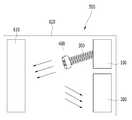
도 7은 본 발명의 실시예에 따른 센서유닛의 일부 사시도이다.7 is a partial perspective view of a sensor unit according to an embodiment of the present invention.
도 7을 참조하면, 상기 송신부(400)는 상기 탄성부재(300)의 단부에 체결되고, 상기 송신부(400)는 전방에 십자 모양의 격자가 형성된다. 아울러, 상기 격자(700)에 의해서 4개의 조사면(710)이 형성된다.Referring to FIG. 7, the
상기 4개의 조사면(710)은 각각 모두 조사방향이 다르게 형성되어 보다 넓은 범위로 적외선엘이디를 조사할 수 있다.Each of the four
본 발명의 실시예에서, 자외선은 눈에 보이지 않지만, 사용자에게 이롭지 않기 때문에 사용되지 않으며, 가시광선은 눈에 보이기 때문에 사용하지 않는다. 따라서, 송신부는 안전하고 눈에 보이지 않는 적외선을 조사한다. 아울러, 소비전력을 낮추고, 제어가 용이한 적외선엘이디를 사용한다.In an embodiment of the invention, ultraviolet light is invisible, but not used because it is not beneficial to the user, and visible light is not used because it is visible. Thus, the transmitter emits a safe and invisible infrared light. In addition, it uses an infrared LED that reduces power consumption and is easy to control.
아울러, 본 발명의 실시예에서, 상기 탄성부재가 코일스프링 구조를 가지고 있는 것으로 설명하였으나, 이에 한정되지 않는다. 즉, 상기 탄성부재는 판스프링을 포함하여 상기 송신부가 흔들릴 수 있는 모든 탄성체를 포함할 수 있다.In addition, in the embodiment of the present invention, the elastic member has been described as having a coil spring structure, but is not limited thereto. That is, the elastic member may include all elastic bodies including the leaf springs that can be shaken by the transmitter.
이상으로 본 발명에 관한 바람직한 실시예를 설명하였으나, 본 발명은 상기 실시예에 한정되지 아니하며, 본 발명의 실시예로부터 당해 발명이 속하는 기술분야에서 통상의 지식을 가진 자에 의한 용이하게 변경되어 균등하다고 인정되는 범위의 모든 변경을 포함한다.While the present invention has been described in connection with what is presently considered to be practical exemplary embodiments, it is to be understood that the invention is not limited to the disclosed embodiments, but, on the contrary, And all changes to the scope that are deemed to be valid.
100: 고정부 102: 송신용신호처리제어부
104: 엘이디드라이버 200: 수신부
202: 포토다이오드 204: 아날로그신호처리단
206: 수신용신호처리제어부 300: 탄성부재
400: 송신부 500: 센서유닛
510: 차량 600: 임의의 물체
610: 반사체 620: 케이싱
700: 격자 710: 조사면100: fixed part 102: transmission signal processing control unit
104: LED driver 200: receiver
202: photodiode 204: analog signal processing stage
206: receiving signal processing controller 300: elastic member
400: transmitter 500: sensor unit
510: vehicle 600: any object
610: reflector 620: casing
700: grid 710: irradiation surface
Claims (13)
Translated fromKorean그 일단이 상기 고정부의 외측에 고정되는 탄성부재;
상기 탄성부재의 타단에 장착되어 적외선을 발산하는 송신부;
임의의 물체로부터 반사된 적외선을 수신하는 수신부; 및
상기 수신부에서 수신된 적외선의 특성에 따라서 비정상상태를 판단하는 제어부; 를 포함하는 센서유닛.Fixed part fixed to one side;
An elastic member whose one end is fixed to an outer side of the fixing part;
A transmission unit mounted to the other end of the elastic member to emit infrared rays;
Receiving unit for receiving the infrared light reflected from any object; And
A controller which determines an abnormal state according to the characteristics of the infrared rays received by the receiver; Sensor unit comprising a.
상기 고정부에 충격이나 움직임이 발생되면, 상기 탄성부재의 탄성력에 의해서 상기 송신부가 움직임으로써 송신되는 적외선의 방향이 변동되는 것을 특징으로 하는 센서유닛.In claim 1,
When the impact or movement occurs in the fixed portion, the sensor unit, characterized in that the direction of the infrared ray transmitted by the transmission unit is changed by the elastic force of the elastic member.
상기 송신부는 적외선을 조사하는 적외선엘이디(IR LED)를 포함하는 것을 특징으로 하는 센서유닛.In claim 1,
The transmitting unit is a sensor unit, characterized in that it comprises an infrared LED (IR LED) for irradiating infrared light.
신호를 변조시키는 송신용신호처리제어부; 및
상기 송신용신호처리제어부에서 변조된 신호의 세기를 조절하는 엘이디드라이버; 를 더 포함하고,
상기 적외선엘이디는 상기 엘이디드라이버에서 생성된 신호를 이용하여 적외선을 송신하는 것을 특징으로 하는 센서유닛.4. The method of claim 3,
A transmission signal processing controller for modulating a signal; And
An LED driver for adjusting the strength of the signal modulated by the transmission signal processing controller; Further comprising:
The infrared LED is a sensor unit, characterized in that for transmitting the infrared ray using the signal generated by the LED driver.
상기 송신용신호처리제어부, 및 상기 엘이디드라이버는 상기 고정부에 내장되는 것을 특징으로 하는 센서유닛.5. The method of claim 4,
The transmission signal processing control unit and the LED driver are built in the fixing unit.
상기 엘이디드라이버와 상기 적외선엘이디는 상기 탄성부재를 따라서 신호를 전달하는 것을 특징으로 하는 센서유닛.5. The method of claim 4,
The LED driver and the infrared LED sensor unit, characterized in that for transmitting a signal along the elastic member.
상기 송신부는 조사면의 일부가 격자 처리되고,
격자 처리된 부분을 제외하고 나머지 조사면들은 서로 다른 조사각을 갖는 것을 특징으로 하는 센서유닛.In claim 1,
A part of the irradiation surface is lattice-processed,
Sensor unit, characterized in that the remaining irradiation surfaces except for the lattice treated parts have different irradiation angles.
상기 수신부는,
상기 임의의 물체로부터 반사되는 적외선을 수신하는 포토다이오드; 및
상기 포토다이오드에서 수신된 적외선 신호를 받아서 처리하는 아날로그신호처리단; 을 포함하고,
상기 제어부는 상기 아날로신호처리단에서 처리된 신호를 이용하여 충격 또는 침입 여부를 판단하는 것을 특징으로 하는 센서유닛.In claim 1,
The receiver may further comprise:
A photodiode for receiving infrared light reflected from the arbitrary object; And
An analog signal processing stage receiving and processing an infrared signal received from the photodiode; / RTI >
The control unit is a sensor unit, characterized in that for determining whether the impact or intrusion using the signal processed in the analog signal processing stage.
상기 비정상상태는 침입상태 또는 충격상태를 포함하는 것을 특징으로 하는 센서유닛.In claim 1,
The abnormal state is a sensor unit, characterized in that it comprises an intrusion or shock state.
상기 케이싱의 내측 공간의 일측에 고정되는 고정부;
그 일단이 상기 고정부의 외측에 장착되는 탄성부재;
상기 탄성부재의 타단에 장착되어 적외선을 송신하는 송신부;
상기 케이싱의 내측 공간의 타측에 고정되는 반사체;
반사체로부터 반사된 적외선을 수신하도록 상기 케이싱 내부에 장착되는 수신부; 및
상기 수신부에서 수신된 적외선의 특성에 따라서 충격 또는 침입상태를 판단하는 제어부; 를 포함하고,
상기 송신부에서 발산되는 적외선의 조사방향이 변하도록 상기 송신부는 상기 탄성부재를 통해서 흔들리도록 장착되는 것을 특징으로 하는 센서유닛.A casing in which spaces are formed;
A fixing part fixed to one side of an inner space of the casing;
An elastic member whose one end is mounted to the outside of the fixing part;
A transmission unit mounted to the other end of the elastic member to transmit infrared rays;
A reflector fixed to the other side of the inner space of the casing;
A receiver mounted inside the casing to receive infrared light reflected from a reflector; And
A controller for determining a shock or intrusion state according to the characteristics of the infrared rays received by the receiver; Lt; / RTI >
And the transmitter is mounted to shake through the elastic member so that the irradiation direction of the infrared rays emitted from the transmitter changes.
상기 수신부는,
상기 반사체로부터 반사되는 적외선을 수신하는 포토다이오드; 및
상기 포토다이오드에서 수신된 적외선 신호를 받아서 처리하는 아날로그신호처리단; 을 포함하고,
상기 제어부는 상기 아날로신호처리단에서 처리된 신호를 이용하여 충격 또는 침입여부를 판단하는 것을 특징으로 하는 센서유닛.11. The method of claim 10,
The receiver may further comprise:
A photodiode for receiving infrared light reflected from the reflector; And
An analog signal processing stage receiving and processing an infrared signal received from the photodiode; / RTI >
The control unit is a sensor unit, characterized in that the impact or intrusion using the signal processed by the analog signal processing stage.
그 일단이 상기 고정부의 외측에 고정되는 탄성부재;
상기 탄성부재의 타단에 장착되어 일정한 파장을 발산하는 송신부;
임의의 물체로부터 반사된 파장을 수신하는 수신부; 및
상기 수신부에서 수신된 파장의 특성에 따라서 비정상상태를 판단하는 제어부; 를 포함하는 센서유닛.Fixed part fixed to one side;
An elastic member whose one end is fixed to an outer side of the fixing part;
A transmission unit mounted at the other end of the elastic member to emit a predetermined wavelength;
Receiving unit for receiving the wavelength reflected from any object; And
A controller for determining an abnormal state according to a characteristic of a wavelength received by the receiver; Sensor unit comprising a.
상기 탄성부재는 코일스프링 형태인 것을 특징으로 하는 센서유닛.13. The method of any of claims 1, 10, and 12,
The elastic member is a sensor unit, characterized in that the coil spring form.
Priority Applications (4)
| Application Number | Priority Date | Filing Date | Title |
|---|---|---|---|
| KR1020120116825AKR101338459B1 (en) | 2012-10-19 | 2012-10-19 | Sensor unit |
| US13/711,084US9360371B2 (en) | 2012-10-19 | 2012-12-11 | Sensor unit |
| DE102012224329.1ADE102012224329B4 (en) | 2012-10-19 | 2012-12-21 | Sensor unit |
| CN201210599116.2ACN103777036B (en) | 2012-10-19 | 2012-12-24 | Sensor unit |
Applications Claiming Priority (1)
| Application Number | Priority Date | Filing Date | Title |
|---|---|---|---|
| KR1020120116825AKR101338459B1 (en) | 2012-10-19 | 2012-10-19 | Sensor unit |
Publications (1)
| Publication Number | Publication Date |
|---|---|
| KR101338459B1true KR101338459B1 (en) | 2013-12-10 |
Family
ID=49987624
Family Applications (1)
| Application Number | Title | Priority Date | Filing Date |
|---|---|---|---|
| KR1020120116825AActiveKR101338459B1 (en) | 2012-10-19 | 2012-10-19 | Sensor unit |
Country Status (4)
| Country | Link |
|---|---|
| US (1) | US9360371B2 (en) |
| KR (1) | KR101338459B1 (en) |
| CN (1) | CN103777036B (en) |
| DE (1) | DE102012224329B4 (en) |
Cited By (1)
| Publication number | Priority date | Publication date | Assignee | Title |
|---|---|---|---|---|
| CN114314239A (en)* | 2022-03-07 | 2022-04-12 | 山东梯配网络科技有限公司 | Elevator trapping automatic alarm system based on Internet of things |
Families Citing this family (1)
| Publication number | Priority date | Publication date | Assignee | Title |
|---|---|---|---|---|
| RU183792U1 (en)* | 2017-07-11 | 2018-10-02 | Дмитрий Валерьевич Вахромеев | A device for remotely notifying the owner of a violation of the immunity of his vehicle |
Citations (4)
| Publication number | Priority date | Publication date | Assignee | Title |
|---|---|---|---|---|
| JP2005178489A (en)* | 2003-12-17 | 2005-07-07 | Sumitomo Electric Ind Ltd | Vehicle anti-theft device |
| KR100718635B1 (en)* | 2005-11-18 | 2007-05-15 | 주식회사 에스원 | Infrared detector with adjustable infrared beam output |
| JP2008107309A (en)* | 2006-09-29 | 2008-05-08 | Furukawa Electric Co Ltd:The | Impact vibration detector |
| KR20120036204A (en)* | 2010-10-07 | 2012-04-17 | 현대모비스 주식회사 | Vehicle antitheft device |
Family Cites Families (20)
| Publication number | Priority date | Publication date | Assignee | Title |
|---|---|---|---|---|
| US3789674A (en)* | 1972-10-27 | 1974-02-05 | Us Navy | Optical accelerometer |
| SE455183B (en)* | 1984-04-13 | 1988-06-27 | Autoliv Dev | DEVICE FOR THE RECOGNITION OF A STANDING, RELIABLE FAITH OF THE BODY IN A VEHICLE SECURITY SYSTEM |
| US5055671A (en)* | 1990-10-03 | 1991-10-08 | Spacelabs, Inc. | Apparatus for detecting transducer movement using a first and second light detector |
| US5218420A (en)* | 1991-04-11 | 1993-06-08 | The Boeing Company | Optical resonance accelerometer |
| DE4224166C2 (en)* | 1991-08-01 | 1994-10-06 | Dynamit Nobel Ag | Passive safety device, in particular gas bag system, to protect the occupants of a vehicle from injuries in the event of accidents |
| US5705809A (en)* | 1996-01-02 | 1998-01-06 | Kershaw; Charles H. | Optical transducer for measuring acceleration or vibration using a curved light reflector |
| KR100193673B1 (en) | 1996-09-24 | 1999-06-15 | 양재신 | Vehicle theft module system using photosensor and pyroelectric infrared sensor |
| KR19980039407A (en) | 1996-11-27 | 1998-08-17 | 박병재 | Anti-theft device by infrared detection |
| DE19927402B4 (en)* | 1999-06-16 | 2005-06-09 | Daimlerchrysler Ag | Vehicle impact detection sensor |
| DE19962472C2 (en)* | 1999-12-22 | 2002-08-01 | Daimler Chrysler Ag | Device for determining a change in distance between two sides of a body, in particular a body part of a vehicle |
| DE10297435T5 (en)* | 2001-11-09 | 2004-09-16 | Canpolar East Inc., St. John's | Mechanical sensor arrangement and impact energy sensor |
| JP2005053371A (en) | 2003-08-05 | 2005-03-03 | Calsonic Kansei Corp | Vehicle theft informing system |
| US7653214B2 (en)* | 2006-01-17 | 2010-01-26 | Avago Technologies Ecbu Ip (Singapore) Pte. Ltd. | Accelerometer utilizing image-based movement tracking |
| US7554674B2 (en)* | 2007-05-23 | 2009-06-30 | Symphony Acoustics, Inc. | Optical displacement sensor |
| CN101545921B (en)* | 2008-03-25 | 2011-12-14 | 鸿富锦精密工业(深圳)有限公司 | Accelerometer |
| EP2277751A2 (en)* | 2008-04-21 | 2011-01-26 | Fsc Co., Ltd. | Raindrop sensor |
| US8760631B2 (en)* | 2010-01-27 | 2014-06-24 | Intersil Americas Inc. | Distance sensing by IQ domain differentiation of time of flight (TOF) measurements |
| DE102010019813A1 (en)* | 2010-05-06 | 2011-11-10 | Siemens Aktiengesellschaft | Fiber optic vibration sensor |
| US8395109B2 (en)* | 2010-05-25 | 2013-03-12 | The Jim Henson Company, Inc. | Motion sensor for detecting bending or pivoting |
| TWI474003B (en)* | 2012-09-20 | 2015-02-21 | Pixart Imaging Inc | Optical accelerometer |
- 2012
- 2012-10-19KRKR1020120116825Apatent/KR101338459B1/enactiveActive
- 2012-12-11USUS13/711,084patent/US9360371B2/enactiveActive
- 2012-12-21DEDE102012224329.1Apatent/DE102012224329B4/enactiveActive
- 2012-12-24CNCN201210599116.2Apatent/CN103777036B/enactiveActive
Patent Citations (4)
| Publication number | Priority date | Publication date | Assignee | Title |
|---|---|---|---|---|
| JP2005178489A (en)* | 2003-12-17 | 2005-07-07 | Sumitomo Electric Ind Ltd | Vehicle anti-theft device |
| KR100718635B1 (en)* | 2005-11-18 | 2007-05-15 | 주식회사 에스원 | Infrared detector with adjustable infrared beam output |
| JP2008107309A (en)* | 2006-09-29 | 2008-05-08 | Furukawa Electric Co Ltd:The | Impact vibration detector |
| KR20120036204A (en)* | 2010-10-07 | 2012-04-17 | 현대모비스 주식회사 | Vehicle antitheft device |
Cited By (1)
| Publication number | Priority date | Publication date | Assignee | Title |
|---|---|---|---|---|
| CN114314239A (en)* | 2022-03-07 | 2022-04-12 | 山东梯配网络科技有限公司 | Elevator trapping automatic alarm system based on Internet of things |
Also Published As
| Publication number | Publication date |
|---|---|
| DE102012224329B4 (en) | 2020-08-13 |
| US9360371B2 (en) | 2016-06-07 |
| DE102012224329A1 (en) | 2014-04-24 |
| CN103777036A (en) | 2014-05-07 |
| US20140110580A1 (en) | 2014-04-24 |
| CN103777036B (en) | 2018-03-23 |
Similar Documents
| Publication | Publication Date | Title |
|---|---|---|
| US12379520B2 (en) | Light curtain safety system | |
| US20190064353A1 (en) | Remote power safety system | |
| MXPA02002509A (en) | Detection device. | |
| US20050231353A1 (en) | Intrusion detection system including over-under passive infrared optics and a microwave transceiver | |
| CN108291967A (en) | Use the site safety device of laser radar | |
| EP2053575A1 (en) | Smoke detectors | |
| US20180190084A1 (en) | An alert device, system and method | |
| WO2008144749A1 (en) | Invisible scanning safety system | |
| JP2013109440A (en) | Security camera apparatus | |
| KR101652076B1 (en) | Fire detector | |
| KR101338459B1 (en) | Sensor unit | |
| JP2014157124A (en) | Person detection device | |
| JP2014182723A5 (en) | ||
| ES2382699T3 (en) | Device for controlling a driven motion element, in particular a door or a portal | |
| KR20110082810A (en) | Security device using plane heat sensor | |
| JP5426940B2 (en) | Lighting control system and remote controller | |
| ES2620989T3 (en) | Equipment and procedure for adjusting the sound intensity of an acoustic signal to signal a state of a domestic appliance and domestic appliance | |
| JP6427772B2 (en) | Battery-powered security device | |
| KR102654490B1 (en) | Apparatus and system for sterilizing using UV LED and method of operating the same | |
| JP2016520972A (en) | Functional control of space | |
| JP2013069098A (en) | Invasion monitoring device | |
| JP2009188491A (en) | Gooseneck microphone | |
| KR200385668Y1 (en) | Duplex infrared sensor | |
| KR100920062B1 (en) | Detection area display of flame detector | |
| Tuteja et al. | Detailed Survey on Motion Sensing |
Legal Events
| Date | Code | Title | Description |
|---|---|---|---|
| A201 | Request for examination | ||
| PA0109 | Patent application | Patent event code:PA01091R01D Comment text:Patent Application Patent event date:20121019 | |
| PA0201 | Request for examination | ||
| E701 | Decision to grant or registration of patent right | ||
| PE0701 | Decision of registration | Patent event code:PE07011S01D Comment text:Decision to Grant Registration Patent event date:20131031 | |
| GRNT | Written decision to grant | ||
| PR0701 | Registration of establishment | Comment text:Registration of Establishment Patent event date:20131202 Patent event code:PR07011E01D | |
| PR1002 | Payment of registration fee | Payment date:20131202 End annual number:3 Start annual number:1 | |
| PG1601 | Publication of registration | ||
| FPAY | Annual fee payment | Payment date:20171129 Year of fee payment:5 | |
| PR1001 | Payment of annual fee | Payment date:20171129 Start annual number:5 End annual number:5 | |
| FPAY | Annual fee payment | Payment date:20191127 Year of fee payment:7 | |
| PR1001 | Payment of annual fee | Payment date:20191127 Start annual number:7 End annual number:7 | |
| PR1001 | Payment of annual fee | Payment date:20201126 Start annual number:8 End annual number:8 | |
| PR1001 | Payment of annual fee | Payment date:20231120 Start annual number:11 End annual number:11 | |
| PR1001 | Payment of annual fee | Payment date:20241125 Start annual number:12 End annual number:12 |