KR101337855B1 - Apparatus and method for detecting a switch fault - Google Patents
Apparatus and method for detecting a switch faultDownload PDFInfo
- Publication number
- KR101337855B1 KR101337855B1KR1020110000463AKR20110000463AKR101337855B1KR 101337855 B1KR101337855 B1KR 101337855B1KR 1020110000463 AKR1020110000463 AKR 1020110000463AKR 20110000463 AKR20110000463 AKR 20110000463AKR 101337855 B1KR101337855 B1KR 101337855B1
- Authority
- KR
- South Korea
- Prior art keywords
- gpio pin
- switch
- detection
- state
- failure
- Prior art date
- Legal status (The legal status is an assumption and is not a legal conclusion. Google has not performed a legal analysis and makes no representation as to the accuracy of the status listed.)
- Expired - Fee Related
Links
Images


Classifications
- G—PHYSICS
- G01—MEASURING; TESTING
- G01R—MEASURING ELECTRIC VARIABLES; MEASURING MAGNETIC VARIABLES
- G01R31/00—Arrangements for testing electric properties; Arrangements for locating electric faults; Arrangements for electrical testing characterised by what is being tested not provided for elsewhere
- G01R31/327—Testing of circuit interrupters, switches or circuit-breakers
- B—PERFORMING OPERATIONS; TRANSPORTING
- B60—VEHICLES IN GENERAL
- B60L—PROPULSION OF ELECTRICALLY-PROPELLED VEHICLES; SUPPLYING ELECTRIC POWER FOR AUXILIARY EQUIPMENT OF ELECTRICALLY-PROPELLED VEHICLES; ELECTRODYNAMIC BRAKE SYSTEMS FOR VEHICLES IN GENERAL; MAGNETIC SUSPENSION OR LEVITATION FOR VEHICLES; MONITORING OPERATING VARIABLES OF ELECTRICALLY-PROPELLED VEHICLES; ELECTRIC SAFETY DEVICES FOR ELECTRICALLY-PROPELLED VEHICLES
- B60L58/00—Methods or circuit arrangements for monitoring or controlling batteries or fuel cells, specially adapted for electric vehicles
- B60L58/10—Methods or circuit arrangements for monitoring or controlling batteries or fuel cells, specially adapted for electric vehicles for monitoring or controlling batteries
- B—PERFORMING OPERATIONS; TRANSPORTING
- B60—VEHICLES IN GENERAL
- B60R—VEHICLES, VEHICLE FITTINGS, OR VEHICLE PARTS, NOT OTHERWISE PROVIDED FOR
- B60R16/00—Electric or fluid circuits specially adapted for vehicles and not otherwise provided for; Arrangement of elements of electric or fluid circuits specially adapted for vehicles and not otherwise provided for
- B60R16/02—Electric or fluid circuits specially adapted for vehicles and not otherwise provided for; Arrangement of elements of electric or fluid circuits specially adapted for vehicles and not otherwise provided for electric constitutive elements
- G—PHYSICS
- G01—MEASURING; TESTING
- G01R—MEASURING ELECTRIC VARIABLES; MEASURING MAGNETIC VARIABLES
- G01R1/00—Details of instruments or arrangements of the types included in groups G01R5/00 - G01R13/00 and G01R31/00
- G01R1/02—General constructional details
- G01R1/06—Measuring leads; Measuring probes
- G01R1/067—Measuring probes
- G—PHYSICS
- G01—MEASURING; TESTING
- G01R—MEASURING ELECTRIC VARIABLES; MEASURING MAGNETIC VARIABLES
- G01R19/00—Arrangements for measuring currents or voltages or for indicating presence or sign thereof
- G01R19/165—Indicating that current or voltage is either above or below a predetermined value or within or outside a predetermined range of values
- G01R19/16566—Circuits and arrangements for comparing voltage or current with one or several thresholds and for indicating the result not covered by subgroups G01R19/16504, G01R19/16528, G01R19/16533
- G01R19/1659—Circuits and arrangements for comparing voltage or current with one or several thresholds and for indicating the result not covered by subgroups G01R19/16504, G01R19/16528, G01R19/16533 to indicate that the value is within or outside a predetermined range of values (window)
Landscapes
- Engineering & Computer Science (AREA)
- Physics & Mathematics (AREA)
- General Physics & Mathematics (AREA)
- Mechanical Engineering (AREA)
- Life Sciences & Earth Sciences (AREA)
- Sustainable Development (AREA)
- Sustainable Energy (AREA)
- Power Engineering (AREA)
- Transportation (AREA)
- Testing Of Short-Circuits, Discontinuities, Leakage, Or Incorrect Line Connections (AREA)
Abstract
Translated fromKoreanDescription
Translated fromKorean본 발명은 차량용 전자제어장치내에 설치되어 스위치의 고장을 검출하기 위한 장치 및 그 검출 방법에 관한 것으로, 상세하게는 차량용 전자제어장치에서 상대적으로 비싼 자원에 속하는 ADC 채널의 수를 줄이고, 일반적으로 여유분이 상당히 존재하는 GPIO포트를 활용하여 차량내에 설치되는 스위치의 고장을 검출할 수 있는 스위치 고장 검출 장치 및 그 검출 방법에 관한 것이다.BACKGROUND OF THE INVENTION 1. Field of the Invention The present invention relates to a device for detecting a failure of a switch installed in an electronic control device for a vehicle and a detection method thereof. The present invention relates to a switch failure detection device and a detection method thereof capable of detecting a failure of a switch installed in a vehicle by utilizing a significantly existing GPIO port.
종래의 경우 차량용 전자제어장치에서 스위치의 고장을 검출하기 위해서는 ADC 채널이나 전자제어장치내의 MCU에 구비된 GPIO 핀을 이용할 수 있다. 그러나, 종래의 경우 GPIO 핀을 이용하여 스위치 고장 여부를 검출하기 위해 그라운드 쇼트만을 검출할 수 있을 뿐 개방 고장이나 배터리 쇼트 고장을 검출할 수 없었다.In the related art, in order to detect a failure of a switch in a vehicle electronic controller, a GPIO pin provided in an ADC channel or an MCU in the electronic controller may be used. However, in the related art, only a ground short can be detected to detect a switch failure using a GPIO pin, and thus an open failure or a battery short failure cannot be detected.
한편, ADC를 이용하여 스위치 고장 여부를 검출할 경우에는 모든 고장이 검출 가능하지만 ADC 채널이라는 상대적으로 비싼 자원을 사용해야하는 단점이 있다. 스위치가 다수 존재하는 시스템이라면 이것으로 인하여 MCU의 사양이 바뀔 가능성이 크다. 또한, ADC채널이 많은 MCU사양의 경우 가격이 상승하게 되는 문제점이 있다.On the other hand, when detecting a switch failure using the ADC, all the failures can be detected, but there is a disadvantage in that a relatively expensive resource called an ADC channel is used. In systems with many switches, this is likely to change the specifications of the MCU. In addition, there is a problem that the price is increased in the case of the MCU specifications with a large number of ADC channels.
본 발명이 해결하려는 과제는, 상술한 종래의 문제점을 해결하기 위하여 차량용 전자제어장치에서 상대적으로 비싼 자원에 속하는 ADC 채널의 수를 줄이고, 일반적으로 여유분이 상당히 존재하는 GPIO포트를 활용하여 차량내에 설치되는 스위치의 고장을 검출할 수 있는 스위치 고장 검출 장치 및 그 고장 검출 방법을 제공하는데 있다.The problem to be solved by the present invention is to reduce the number of ADC channels belonging to a relatively expensive resource in the vehicle electronic control device, in order to solve the above-mentioned conventional problems, and installed in the vehicle by utilizing a GPIO port that generally has a considerable margin It is an object of the present invention to provide a switch failure detection device and a failure detection method capable of detecting a failure of a switch.
본 발명에 의하면, 차량용 전자제어장치내에 설치되어 스위치의 고장을 검출하기 위한 장치로서, 배터리 및 상기 스위치에 전기적으로 연결되어 상기 스위치의 전압 상태를 검출하기 위한 검출용 GPIO핀; 상기 검출용 GPIO핀에 전기적으로 연결되어 상기 스위치의 고장 여부를 진단하기 위한 상태값이 가변적으로 설정되는 제어용 GPIO핀; 상기 제어용 GPIO핀에 상기 스위치의 고장 여부를 진단하기 위한 상태값을 가변적으로 설정하는 상태 설정부; 및 상기 제어용 GPIO 핀에 가변적으로 진단을 위한 상태값이 설정되도록 상기 상태 설정부를 제어하며, 상기 검출용 GPIO핀을 통해 검출된 스위치의 전압상태에 따라 상기 스위치의 고장여부를 검출하도록 고장 진단을 수행하는 고장 진단부를 포함하는 스위치 고장 검출 장치가 제공된다.According to the present invention, an apparatus for detecting a failure of a switch installed in an electronic control device for a vehicle, comprising: a detection GPIO pin electrically connected to a battery and the switch for detecting a voltage state of the switch; A control GPIO pin electrically connected to the detection GPIO pin to variably set a state value for diagnosing a failure of the switch; A state setting unit for variably setting a state value for diagnosing a failure of the switch to the control GPIO pin; And controlling the state setting unit to variably set a state value for diagnosis on the control GPIO pin, and performing a fault diagnosis to detect whether the switch has failed according to the voltage state of the switch detected through the detecting GPIO pin. Provided is a switch failure detection device including a failure diagnosis unit.
바람직하게는, 상기 스위치 고장 검출 장치는 상기 배터리 및 상기 스위치 사이에 전압 분압을 위해 연결된 제1 저항; 상기 스위치와 상기 검출용 GPIO핀 사이에 전압 분압을 위해 연결된 제2 저항; 및 상기 검출용 GPIO핀과 상기 제어용 GPIO핀 사이에 연결되어 상기 검출용 GPIO핀 및 상기 제어용 GPIO 핀을 보호하기 위한 제3 저항을 더 포함할 수 있다.Advantageously, said switch failure detection device comprises: a first resistor coupled between said battery and said switch for voltage divider; A second resistor connected between the switch and the detection GPIO pin for voltage division; And a third resistor connected between the detection GPIO pin and the control GPIO pin to protect the detection GPIO pin and the control GPIO pin.
상기 고장 진단부는 상기 검출용 GPIO 핀과 상기 제어용 GPIO 핀의 디폴트 상태를 하이 임피던스로 설정한 상태에서 상기 검출용 GPIO 핀을 통해 검출된 신호가 하이 상태인 경우 상기 제어용 GPIO 핀을 로우 상태로 설정하고, 상기 검출용 GPIO 핀을 통해 검출된 신호가 로우 상태이면 스위치를 푸쉬하지 않은 정상 상태로 진단하고, 로우 상태가 아니면 배터리 쇼트 고장으로 진단하는 동작을 수행할 수 있다. 또한, 상기 고장 진단부는 상기 검출용 GPIO 핀과 상기 제어용 GPIO 핀의 디폴트 상태를 하이 임피던스로 설정한 상태에서 상기 검출용 GPIO 핀을 통해 검출된 신호가 로우 상태인 경우 상기 제어용 GPIO 핀을 하이상태로 설정하고, 상기 검출용 GPIO 핀을 통해 검출된 신호가 하이 상태이면 개방 고장으로 진단하고, 상기 제어용 GPIO 핀을 하이상태로 설정한 상태에서 일정 시간이 경과하기 전에 상기 검출용 GPIO 핀을 통해 검출된 신호가 하이 상태로 복귀하면 스위치를 푸쉬한 정상상태로 진단하고, 복귀하지 않는 경우 그라운드 쇼트 고장으로 진단하는 동작을 수행할 수 있다.The fault diagnosis unit sets the control GPIO pin to a low state when a signal detected through the detection GPIO pin is high while the default states of the detection GPIO pin and the control GPIO pin are set to high impedance. When the signal detected through the detection GPIO pin is in a low state, the switch may be diagnosed as a normal state without being pushed, and when it is not in the low state, the switch may be diagnosed as a battery short failure. The fault diagnosis unit may set the control GPIO pin to a high state when a signal detected through the detection GPIO pin is low while the default states of the detection GPIO pin and the control GPIO pin are set to high impedance. If the signal detected through the detection GPIO pin is set to a high state, it is diagnosed as an open fault, and detected by the detection GPIO pin before a predetermined time has elapsed while the control GPIO pin is set to a high state. If the signal returns to the high state, the switch can be diagnosed as a pushed normal state, and if not, the switch can be diagnosed as a ground short fault.
본 발명의 다른 측면에 의하면, 배터리 및 스위치에 전기적으로 연결되어 상기 스위치의 전압 상태를 검출하기 위한 검출용 GPIO핀; 및 상기 검출용 GPIO핀에 전기적으로 연결되어 상기 스위치의 고장 여부를 진단하기 위한 상태값이 가변적으로 설정되는 제어용 GPIO핀을 포함하여 차량용 전자제어장치내에 설치되는 스위치 고장 검출 장치의 고장 검출 방법으로서, 상기 검출용 GPIO 핀과 상기 제어용 GPIO 핀의 디폴트 상태를 하이 임피던스로 설정하는 단계; 및 상기 제어용 GPIO핀에 상기 스위치의 고장 여부를 진단하기 위한 상태값을 가변적으로 설정하고 상기 검출용 GPIO핀을 통해 검출된 스위치의 전압상태에 따라 상기 스위치의 고장여부를 검출하도록 고장 진단을 수행하는 단계를 포함하는 스위치 고장 검출 장치의 고장 검출 방법이 제공된다.According to another aspect of the invention, the GPIO pin for detecting the voltage state of the switch electrically connected to the battery and the switch; And a control GPIO pin electrically connected to the detection GPIO pin and configured to variably set a state value for diagnosing a failure of the switch. Setting a default state of the detection GPIO pin and the control GPIO pin to a high impedance; And variably setting a state value for diagnosing a failure of the switch to the control GPIO pin and performing a fault diagnosis to detect whether the switch has failed according to a voltage state of the switch detected through the detection GPIO pin. Provided is a failure detection method of a switch failure detection device comprising a step.
바람직하게는, 상기 고장 진단을 수행하는 단계는, 상기 검출용 GPIO 핀과 상기 제어용 GPIO 핀의 디폴트 상태를 하이 임피던스로 설정한 상태에서 상기 검출용 GPIO 핀을 통해 검출된 신호가 하이 상태인 경우 상기 제어용 GPIO 핀을 로우 상태로 설정하고, 상기 검출용 GPIO 핀을 통해 검출된 신호가 로우 상태이면 스위치를 푸쉬하지 않은 정상 상태로 진단하고, 로우 상태가 아니면 배터리 쇼트 고장으로 진단하는 단계; 및 상기 검출용 GPIO 핀과 상기 제어용 GPIO 핀의 디폴트 상태를 하이 임피던스로 설정한 상태에서 상기 검출용 GPIO 핀을 통해 검출된 신호가 로우 상태인 경우 상기 제어용 GPIO 핀을 하이상태로 설정하고, 상기 검출용 GPIO 핀을 통해 검출된 신호가 하이 상태이면 개방 고장으로 진단하고, 상기 제어용 GPIO 핀을 하이상태로 설정한 상태에서 일정 시간이 경과하기 전에 상기 검출용 GPIO 핀을 통해 검출된 신호가 하이 상태로 복귀하면 스위치를 푸쉬한 정상상태로 진단하고, 복귀하지 않는 경우 그라운드 쇼트 고장으로 진단하는 단계를 포함할 수 있다.Preferably, the performing of the fault diagnosis may include: when a signal detected through the detection GPIO pin is high while the default states of the detection GPIO pin and the control GPIO pin are set to high impedance, Setting a control GPIO pin to a low state, diagnosing the switch as a normal state not pushed if a signal detected through the detection GPIO pin is low, and diagnosing a battery short failure if not; And setting the control GPIO pin to a high state when the signal detected through the detection GPIO pin is low while the default states of the detection GPIO pin and the control GPIO pin are set to high impedance. If the signal detected through the GPIO pin is high, it is diagnosed as an open fault, and the signal detected through the GPIO pin is detected to be high before a predetermined time has elapsed while the control GPIO pin is set to the high state. Diagnosing the switch as a pushed normal state when returning, and diagnosing the switch as a ground short failure when not returning.
바람직하게는, 상기 스위치 고장 검출 장치의 고장 검출 방법은 고장 진단 결과를 표시부를 통해 시각적으로 표시하는 단계를 더 포함할 수 있다.Preferably, the failure detection method of the switch failure detection apparatus may further include visually displaying a failure diagnosis result through a display unit.
본 발명에 의하면, 차량용 전자제어장치에서 GPIO 포트와 저항을 사용하여 차량내에 설치되는 스위치의 고장을 검출할 수 있게 함으로써, 종래에 상대적으로 비싼 자원에 속하는 ADC 채널을 대체하여 차량용 전자제어장치의 단가를 낮출 수 있는 효과를 제공할 수 있다.According to the present invention, it is possible to detect a failure of a switch installed in a vehicle by using a GPIO port and a resistor in a vehicle electronic control device, thereby replacing the ADC channel belonging to a relatively expensive resource in the related art. It can provide an effect that can be lowered.
또한, 본 발명에 의하면, 스위치 고장을 검출함에 있어 그라운드 쇼트 고장 검출 뿐만 아니라 개방 고장이나 배터리 쇼트 고장을 검출할 수 있는 효과를 제공할 수 있다.In addition, according to the present invention, it is possible to provide an effect capable of detecting not only the ground short fault but also an open fault or a battery short fault in detecting a switch fault.
도 1은 본 발명의 일실시예에 따른 스위치 고장 검출 장치를 설명하기 위한 도면이다.
도 2는 본 발명의 일실시예에 따른 스위치 고장 검출 장치의 회로를 설명하기 위한 도면이다.
도 3 및 도 4는 본 발명의 일실시예에 따른 스위치 고장 검출 장치의 고장 검출 방법을 설명하기 위한 도면이다.1 is a view for explaining a switch failure detection apparatus according to an embodiment of the present invention.
2 is a view for explaining a circuit of a switch failure detection apparatus according to an embodiment of the present invention.
3 and 4 are views for explaining a failure detection method of the switch failure detection apparatus according to an embodiment of the present invention.
이하, 첨부된 도면을 참조하여 본 발명의 바람직한 실시예를 설명하도록 한다.Hereinafter, exemplary embodiments of the present invention will be described with reference to the accompanying drawings.
도 1은 본 발명의 일실시예에 따른 스위치 고장 검출 장치를 설명하기 위한 도면이고, 도 2는 본 발명의 일실시예에 따른 스위치 고장 검출 장치의 회로를 설명하기 위한 도면이다.1 is a view for explaining a switch failure detection apparatus according to an embodiment of the present invention, Figure 2 is a view for explaining a circuit of a switch failure detection apparatus according to an embodiment of the present invention.
도 1 및 도 2를 참조하면, 본 발명의 일실시예에 따른 스위치 고장 검출 장치는 차량용 전자제어장치(ECU)(200)내에 설치되어 스위치(100)의 고장 검출을 수행한다. 스위치 고장 검출 장치는 검출용 GPIO핀(210), 제어용 GPIO핀(220), 상태 설정부(230), 고장 진단부(240), 표시부(250)를 포함할 수 있다.1 and 2, a switch failure detection apparatus according to an embodiment of the present invention is installed in a vehicle electronic control unit (ECU) 200 to perform failure detection of a
검출용 GPIO핀(210)은 배터리와 스위치(100)에 전기적으로 연결되어 스위치(100)의 전압 상태를 검출하기 위한 GPIO 핀이다.The
제어용 GPIO핀(220)은 스위치(100)의 고장 여부를 진단하기 위한 상태값이 가변적으로 설정되는 GPIO 핀이며, 검출용 GPIO 핀(210)에 도 2에 도시된 바와 같은 보호용 저항을 통해 전기적으로 연결된다.The
도 2를 참조하면, 스위치 고장 검출 장치는 제1 저항(R1), 제2 저항(R2), 제3 저항(R3)을 포함한다. 제1 저항(R1)은 배터리 및 스위치(100) 사이에 전압 분압을 위해 연결된다. 제2 저항(R2)은 스위치(100)와 검출용 GPIO핀(210) 사이에 전압 분압을 위해 연결된다. 제3 저항(R3)은 검출용 GPIO핀(210)과 제어용 GPIO핀(220) 사이에 연결되어 검출용 GPIO핀(210) 및 제어용 GPIO핀(220)을 보호한다.2, the switch failure detection device includes a first resistor R1, a second resistor R2, and a third resistor R3. The first resistor R1 is connected for voltage division between the battery and the
제3 저항(R3)은 ECU(200)내에서 GPIO핀(210) 및 제어용 GPIO핀(220)이 구비된 MCU(미도시됨)의 전류 용량을 고려하여 예컨대, 10k 이상의 큰 저항을 사용한다. 이 경우, 제1 저항(R1)은 제3 저항(R3)의 약 10 x R의 크기로 설정될 수 있다. 한편, 제2 저항(R2)은 제3 저항(R3)의 약 5 x R의 크기로 설정될 수 있다.The third resistor R3 uses, for example, a large resistor of 10k or more in consideration of the current capacity of the MCU (not shown) provided with the
상태 설정부(230)는 제어용 GPIO핀(220)에 스위치(100)의 고장 여부를 진단하기 위한 상태값을 가변적으로 설정한다. 예컨대, 상태 설정부(230)는 고장 진단부(240)의 제어를 받아 제어용 GPIO 핀(220)의 상태값을 설정한다. 예컨대, 검출용 GPIO 핀(210)과 제어용 GPIO 핀(220)의 디폴트 상태가 하이 임피던스로 설정한 상태에서 고장 진단 동작이 수행된 상태에서, 검출용 GPIO 핀(210)을 통해 검출된 신호가 하이 상태인 경우, 고장 진단부(240)의 제어 신호에 따라 제어용 GPIO 핀을 로우 상태로 설정한다.The
아울러, 상태 설정부(230)는 검출용 GPIO 핀(210)과 제어용 GPIO 핀(220)의 디폴트 상태가 하이 임피던스로 설정된 상태에서 검출용 GPIO 핀(210)을 통해 검출된 신호가 로우 상태인 경우 고장 진단부(240)의 제어 신호에 따라 제어용 GPIO 핀(220)을 하이상태로 설정한다.In addition, when the signal detected through the
고장 진단부(240)는 제어용 GPIO 핀(220)에 가변적으로 진단을 위한 상태값이 설정되도록 상태 설정부(230)를 제어한다. 아울러, 고장 진단부(240)는 검출용 GPIO핀(210)을 통해 검출된 스위치(100)의 전압상태에 따라 스위치(100)의 고장여부를 검출하도록 고장 진단을 수행한다.The
고장 진단부(240)는 검출용 GPIO 핀(210)과 제어용 GPIO 핀(220)의 디폴트 상태를 하이 임피던스로 설정한 상태에서 고장 진단 동작을 수행한다. 고장 진단부(240)는 검출용 GPIO 핀(210)을 통해 검출된 신호가 하이 상태인 경우 상태 설정부(230)에 제어 신호를 출력하여 제어용 GPIO 핀을 로우 상태로 설정한다. 그 다음 고장 진단부(240)는 검출용 GPIO 핀(210)을 통해 검출된 신호가 로우 상태이면 스위치를 푸쉬하지 않은 정상 상태로 진단한다. 한편, 로우 상태가 아니면 배터리 쇼트 고장으로 진단하는 동작을 수행한다. 아울러, 고장 진단부(240)는 검출용 GPIO 핀(210)과 제어용 GPIO 핀(220)의 디폴트 상태를 하이 임피던스로 설정한 상태에서 상기 검출용 GPIO 핀을 통해 검출된 신호가 로우 상태인 경우 상대 설정부(230)에 제어신호를 출력하여 제어용 GPIO 핀(220)을 하이상태로 설정한다.The
그 다음, 검출용 GPIO 핀(210)을 통해 검출된 신호가 하이 상태이면 개방 고장으로 진단한다. 한편, 고장 진단부(240)는 제어용 GPIO 핀(220)을 하이상태로 설정한 상태에서 일정 시간이 경과하기 전에 검출용 GPIO 핀(210)을 통해 검출된 신호가 하이 상태로 복귀하면 스위치(100)를 푸쉬한 정상상태로 진단한다. 만약, 복귀하지 않는 경우에는 그라운드 쇼트 고장으로 진단한다.Next, when the signal detected through the
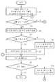
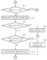
도 3 및 도 4는 본 발명의 일실시예에 따른 스위치 고장 검출 장치의 고장 검출 방법을 설명하기 위한 도면이다.3 and 4 are views for explaining a failure detection method of the switch failure detection apparatus according to an embodiment of the present invention.
도 3 및 도 4를 참조하면, 고장 진단부(240)는 고장 진단수행하기 위해 검출용 GPIO 핀(210)과 제어용 GPIO 핀(220)의 디폴트 상태를 하이 임피던스로 설정한다(S1).3 and 4, the
고장 진단부(240)는 검출용 GPIO 핀(210)을 통해 검출된 신호가 하이 상태인지 여부를 판단한다(S3). 판단 결과 검출된 신호가 하이 상태인 경우, 고장 진단부(240)는 상태 설정부(230)에 제어 신호를 출력하여 제어용 GPIO 핀(220)을 로우 상태로 설정한다(S4).The
그 다음 고장 진단부(240)는 검출용 GPIO 핀(210)을 통해 검출된 신호가 로우 상태인지 여부를 판단한다(S5). 판단 결과, 검출된 신호가 로우 상태이면 고장 진단부(240)는 스위치를 푸쉬하지 않은 정상 상태로 진단한다(S6).The
한편, 단계 S6의 판단 결과, 검출된 신호가 로우 상태가 아니면 배터리 쇼트 고장으로 진단한다(S7). 고장 진단부(240)는 표시부(250)를 통해 진단 결과를 표시한다(S8). 그 다음 고장 진단부(240)는 진단을 계속할 것인지 여부를 판단하여(S9) 진단을 계속할 경우 상태 설정부(230)를 제어하여 제어용 GPIO 핀(220)을 하이 임피던스로 설정한다. 계속적으로 스위치(100)에 대한 고장 진단을 수행한다.On the other hand, if the detected signal is not in the low state as a result of the determination in step S6, it is diagnosed as a battery short failure (S7). The
한편, 고장 진단부(240)는 단계 S3에서 상기 검출용 GPIO 핀을 통해 검출된 신호가 하이 상태가 아닌 경우, 검출 신호가 로우 상태인지 여부를 판단한다(S11). 단계 S11의 판단 결과, 검출 신호가 로우 상태인 경우 고장 진단부(240)는 상태 설정부(230)에 제어신호를 출력하여 제어용 GPIO 핀(220)을 하이상태로 설정한다(S12). 한편, 단계 11의 판단 결과 로우 상태가 아니면 다시 단계 S3의 이전으로 진행한다.Meanwhile, when the signal detected through the detection GPIO pin is not in the high state in step S3, the
고장 진단부(240)는 단계 S 12를 수행한 다음, 검출용 GPIO 핀(210)을 통해 검출된 신호가 하이 상태인지 여부를 판단한다(S13). 판단 결과 검출된 신호가 하이 상태이면 고장 진단부(240)는 개방 고장으로 진단한다(S14). 한편, 고장 진단부(240)는 제어용 GPIO 핀(220)을 하이상태로 설정한 상태에서 일정 시간(예컨대, 1분 이상)이 경과하기 전에 검출용 GPIO 핀(210)을 통해 검출된 신호가 하이 상태로 복귀하는지 여부를 판단한다(S15). 판단 결과, 복귀하지 않는 경우에는 그라운드 쇼트 고장으로 진단하고(S16), 판단결과, 하이 상태로 복귀하면 스위치(100)를 푸쉬한 정상상태로 진단한다(S17).The
이상의 본 발명은 상기에 기술된 실시예들에 의해 한정되지 않고, 당업자들에 의해 다양한 변형 및 변경을 가져올 수 있으며, 이는 첨부된 청구항에서 정의되는 본 발명의 취지와 범위에 포함된다.The invention being thus described, it will be obvious that the same way may be varied in many ways. Such modifications are intended to be within the spirit and scope of the invention as defined by the appended claims.
100 : 스위치 200 : ECU
210 : 검출용 GPIO 핀 220 : 제어용 GPIO 핀
230 : 상태 설정부 240 : 고장 진단부
250 : 표시부100: switch 200: ECU
210: GPIO pin for detection 220: GPIO pin for control
230: state setting unit 240: fault diagnosis unit
250: display unit
Claims (6)
Translated fromKorean배터리 및 상기 스위치에 전기적으로 연결되어 상기 스위치의 전압 상태를 검출하기 위한 검출용 GPIO핀;
상기 검출용 GPIO핀에 전기적으로 연결되어 상기 스위치의 고장 여부를 진단하기 위한 상태값이 가변적으로 설정되는 제어용 GPIO핀;
상기 제어용 GPIO핀에 상기 스위치의 고장 여부를 진단하기 위한 상태값을 가변적으로 설정하는 상태 설정부; 및
상기 제어용 GPIO 핀에 가변적으로 진단을 위한 상태값이 설정되도록 상기 상태 설정부를 제어하며, 상기 검출용 GPIO핀을 통해 검출된 스위치의 전압상태에 따라 상기 스위치의 고장여부를 검출하도록 고장 진단을 수행하는 고장 진단부를 포함하는 스위치 고장 검출 장치.It is installed in an electronic control device for a vehicle and used to detect a failure of a switch.
A detection GPIO pin electrically connected to a battery and the switch for detecting a voltage state of the switch;
A control GPIO pin electrically connected to the detection GPIO pin to variably set a state value for diagnosing a failure of the switch;
A state setting unit for variably setting a state value for diagnosing a failure of the switch to the control GPIO pin; And
Controlling the state setting unit to variably set a state value for diagnosis on the control GPIO pin, and performing fault diagnosis to detect whether the switch has failed according to the voltage state of the switch detected through the detecting GPIO pin. Switch failure detection device comprising a failure diagnosis unit.
상기 배터리 및 상기 스위치 사이에 전압 분압을 위해 연결된 제1 저항; 및
상기 스위치와 상기 검출용 GPIO핀 사이에 전압 분압을 위해 연결된 제2 저항;
상기 검출용 GPIO핀과 상기 제어용 GPIO핀 사이에 연결되어 상기 검출용 GPIO핀 및 상기 제어용 GPIO 핀을 보호하기 위한 제3 저항을 더 포함하는 스위치 고장 검출 장치.The method according to claim 1,
A first resistor coupled between the battery and the switch for voltage divider; And
A second resistor connected between the switch and the detection GPIO pin for voltage division;
And a third resistor connected between the detection GPIO pin and the control GPIO pin to protect the detection GPIO pin and the control GPIO pin.
상기 고장 진단부는 상기 검출용 GPIO 핀과 상기 제어용 GPIO 핀의 디폴트 상태를 하이 임피던스로 설정한 상태에서 상기 검출용 GPIO 핀을 통해 검출된 신호가 하이 상태인 경우 상기 제어용 GPIO 핀을 로우 상태로 설정하고, 상기 검출용 GPIO 핀을 통해 검출된 신호가 로우 상태이면 스위치를 푸쉬하지 않은 정상 상태로 진단하고, 로우 상태가 아니면 배터리 쇼트 고장으로 진단하고,
상기 고장 진단부는 상기 검출용 GPIO 핀과 상기 제어용 GPIO 핀의 디폴트 상태를 하이 임피던스로 설정한 상태에서 상기 검출용 GPIO 핀을 통해 검출된 신호가 로우 상태인 경우 상기 제어용 GPIO 핀을 하이상태로 설정하고, 상기 검출용 GPIO 핀을 통해 검출된 신호가 하이 상태이면 개방 고장으로 진단하고, 상기 제어용 GPIO 핀을 하이상태로 설정한 상태에서 일정 시간이 경과하기 전에 상기 검출용 GPIO 핀을 통해 검출된 신호가 하이 상태로 복귀하면 스위치를 푸쉬한 정상상태로 진단하고, 복귀하지 않는 경우 그라운드 쇼트 고장으로 진단하는 동작을 수행하는 스위치 고장 검출 장치.The method according to claim 1,
The fault diagnosis unit sets the control GPIO pin to a low state when a signal detected through the detection GPIO pin is high while the default states of the detection GPIO pin and the control GPIO pin are set to high impedance. When the signal detected through the detection GPIO pin is in a low state, the switch is diagnosed as a normal state not pushed, and when the signal is not low, the battery short fault is diagnosed.
The fault diagnosis unit sets the control GPIO pin to a high state when a signal detected through the detection GPIO pin is low while the default states of the detection GPIO pin and the control GPIO pin are set to high impedance. If the signal detected through the detection GPIO pin is in a high state, it is diagnosed as an open fault, and the signal detected through the detection GPIO pin is detected before a predetermined time has elapsed while the control GPIO pin is set to a high state. A switch failure detection device for diagnosing a switch as a pushed normal state when it returns to a high state, and for diagnosing a switch as a ground short fault if it does not return.
상기 검출용 GPIO 핀과 상기 제어용 GPIO 핀의 디폴트 상태를 하이 임피던스로 설정하는 단계;
상기 제어용 GPIO핀에 상기 스위치의 고장 여부를 진단하기 위한 상태값을 가변적으로 설정하고 상기 검출용 GPIO핀을 통해 검출된 스위치의 전압상태에 따라 상기 스위치의 고장여부를 검출하도록 고장 진단을 수행하는 단계를 포함하는 스위치 고장 검출 장치의 고장 검출 방법.A detection GPIO pin electrically connected to a battery and a switch for detecting a voltage state of the switch; And a control GPIO pin electrically connected to the detection GPIO pin and configured to variably set a state value for diagnosing a failure of the switch.
Setting a default state of the detection GPIO pin and the control GPIO pin to a high impedance;
Variably setting a status value for diagnosing a failure of the switch to the control GPIO pin and performing a failure diagnosis to detect whether the switch has failed according to a voltage state of the switch detected through the detection GPIO pin. Failure detection method of the switch failure detection device comprising a.
상기 고장 진단을 수행하는 단계는,
상기 검출용 GPIO 핀과 상기 제어용 GPIO 핀의 디폴트 상태를 하이 임피던스로 설정한 상태에서 상기 검출용 GPIO 핀을 통해 검출된 신호가 하이 상태인 경우 상기 제어용 GPIO 핀을 로우 상태로 설정하고, 상기 검출용 GPIO 핀을 통해 검출된 신호가 로우 상태이면 스위치를 푸쉬하지 않은 정상 상태로 진단하고, 로우 상태가 아니면 배터리 쇼트 고장으로 진단하는 단계; 및
상기 검출용 GPIO 핀과 상기 제어용 GPIO 핀의 디폴트 상태를 하이 임피던스로 설정한 상태에서 상기 검출용 GPIO 핀을 통해 검출된 신호가 로우 상태인 경우 상기 제어용 GPIO 핀을 하이상태로 설정하고, 상기 검출용 GPIO 핀을 통해 검출된 신호가 하이 상태이면 개방 고장으로 진단하고, 상기 제어용 GPIO 핀을 하이상태로 설정한 상태에서 일정 시간이 경과하기 전에 상기 검출용 GPIO 핀을 통해 검출된 신호가 하이 상태로 복귀하면 스위치를 푸쉬한 정상상태로 진단하고, 복귀하지 않는 경우 그라운드 쇼트 고장으로 진단하는 단계를 포함하는 스위치 고장 검출 장치의 고장 검출 방법.The method of claim 4,
The performing of the fault diagnosis may include:
The control GPIO pin is set to a low state when the signal detected through the detection GPIO pin is high while the default states of the detection GPIO pin and the control GPIO pin are set to high impedance. Diagnosing the switch as a normal state not pushed if the signal detected through the GPIO pin is low, and diagnosing a battery short failure if it is not low; And
When the signal detected through the detection GPIO pin is low when the default state of the detection GPIO pin and the control GPIO pin is set to high impedance, the control GPIO pin is set to a high state, and the detection for If the signal detected through the GPIO pin is high, it is diagnosed as an open fault, and the signal detected through the detection GPIO pin returns to the high state before a predetermined time has elapsed while the control GPIO pin is set to the high state. Diagnosing the switch as a pushed normal state and diagnosing the switch as a ground short fault if it does not return.
고장 진단 결과를 표시부를 통해 시각적으로 표시하는 단계를 더 포함하는 스위치 고장 검출 장치의 고장 검출 방법.The method of claim 4,
And visually displaying a fault diagnosis result through a display unit.
Priority Applications (1)
| Application Number | Priority Date | Filing Date | Title |
|---|---|---|---|
| KR1020110000463AKR101337855B1 (en) | 2011-01-04 | 2011-01-04 | Apparatus and method for detecting a switch fault |
Applications Claiming Priority (1)
| Application Number | Priority Date | Filing Date | Title |
|---|---|---|---|
| KR1020110000463AKR101337855B1 (en) | 2011-01-04 | 2011-01-04 | Apparatus and method for detecting a switch fault |
Publications (2)
| Publication Number | Publication Date |
|---|---|
| KR20120079261A KR20120079261A (en) | 2012-07-12 |
| KR101337855B1true KR101337855B1 (en) | 2013-12-06 |
Family
ID=46712266
Family Applications (1)
| Application Number | Title | Priority Date | Filing Date |
|---|---|---|---|
| KR1020110000463AExpired - Fee RelatedKR101337855B1 (en) | 2011-01-04 | 2011-01-04 | Apparatus and method for detecting a switch fault |
Country Status (1)
| Country | Link |
|---|---|
| KR (1) | KR101337855B1 (en) |
Cited By (1)
| Publication number | Priority date | Publication date | Assignee | Title |
|---|---|---|---|---|
| KR20200066398A (en) | 2018-11-30 | 2020-06-10 | 아이탑스오토모티브 주식회사 | Failure dection method of dpst switch for vehicle and failure dection device of the same |
Families Citing this family (7)
| Publication number | Priority date | Publication date | Assignee | Title |
|---|---|---|---|---|
| US11255915B2 (en)* | 2018-11-30 | 2022-02-22 | Lg Energy Solution, Ltd. | Switch control apparatus and method |
| CN109901064B (en)* | 2019-03-15 | 2021-02-12 | 西安工程大学 | ICA-LVQ-based high-voltage circuit breaker fault diagnosis method |
| CN110138306B (en)* | 2019-04-11 | 2021-03-09 | 南京航空航天大学 | An electrical excitation doubly salient motor power converter and method thereof |
| KR102803778B1 (en) | 2019-04-23 | 2025-05-07 | 현대자동차주식회사 | System of controlling battery charging or discharging |
| CN110261759B (en)* | 2019-06-28 | 2021-05-07 | 上海移远通信技术股份有限公司 | A damage detection system for chip pins |
| KR102852241B1 (en)* | 2019-07-23 | 2025-08-29 | 현대자동차주식회사 | failure diagnosis device, Vehicle having the same, and method for controlling the same |
| CN116149287A (en)* | 2021-11-19 | 2023-05-23 | 广州优胜汽车科技有限公司 | Pin signal monitoring device and pin signal monitoring circuit |
Citations (3)
| Publication number | Priority date | Publication date | Assignee | Title |
|---|---|---|---|---|
| KR20050071693A (en)* | 2002-11-14 | 2005-07-07 | 화이어 스톰, 아이엔씨. | Power converter circuitry and method |
| KR20090006884A (en)* | 2004-08-24 | 2009-01-15 | 샤프 가부시키가이샤 | Display system |
| US20100130263A1 (en) | 2008-11-21 | 2010-05-27 | Edward Zhang | System and method for dual power source management |
- 2011
- 2011-01-04KRKR1020110000463Apatent/KR101337855B1/ennot_activeExpired - Fee Related
Patent Citations (4)
| Publication number | Priority date | Publication date | Assignee | Title |
|---|---|---|---|---|
| KR20050071693A (en)* | 2002-11-14 | 2005-07-07 | 화이어 스톰, 아이엔씨. | Power converter circuitry and method |
| KR20090006884A (en)* | 2004-08-24 | 2009-01-15 | 샤프 가부시키가이샤 | Display system |
| US20090179745A1 (en) | 2004-08-24 | 2009-07-16 | Sharp Kabushiki Kaisha | Display system |
| US20100130263A1 (en) | 2008-11-21 | 2010-05-27 | Edward Zhang | System and method for dual power source management |
Cited By (1)
| Publication number | Priority date | Publication date | Assignee | Title |
|---|---|---|---|---|
| KR20200066398A (en) | 2018-11-30 | 2020-06-10 | 아이탑스오토모티브 주식회사 | Failure dection method of dpst switch for vehicle and failure dection device of the same |
Also Published As
| Publication number | Publication date |
|---|---|
| KR20120079261A (en) | 2012-07-12 |
Similar Documents
| Publication | Publication Date | Title |
|---|---|---|
| KR101337855B1 (en) | Apparatus and method for detecting a switch fault | |
| US9563313B2 (en) | Display panels with touch functions and fault detection method thereof | |
| JP4715253B2 (en) | Power supply system monitoring device | |
| EP2669693B1 (en) | Parallel operation wire fault detection device and system | |
| CN102736030B (en) | Battery voltage detector | |
| CN201829385U (en) | Press switch with diagnosis function and press key switch device | |
| US20140008970A1 (en) | Ground fault detecting device for an ungrounded circuit | |
| US20170160761A1 (en) | Power distribution unit and fault detecting method | |
| JP2013207961A5 (en) | ||
| CN114002502A (en) | Insulation resistance detection circuit and method | |
| CN105612696A (en) | Electronic control device | |
| KR101487577B1 (en) | Method and apparatus for detecting default of battery pack, and power relay assembly thereof | |
| CN109228870B (en) | Train and train power supply system and electric leakage detection and recovery device and method thereof | |
| KR101826698B1 (en) | Fault Diagnosis Method for Solenoid Valve Of High Pressure Pump And Device Thereof | |
| JP2010271267A (en) | Battery monitoring device | |
| KR101893246B1 (en) | Apparatus for diagnosing state of control line | |
| JP2013242324A (en) | Battery monitoring device | |
| CN109228873B (en) | Train and train power supply system and electric leakage detection and recovery device and method thereof | |
| JP2016161478A (en) | Failure determination device of contactor | |
| CN107450786B (en) | Touch controller, touch panel including the same, and method for detecting circuit failure | |
| KR20140104978A (en) | Method for determining the absence of voltage in an electrical high-voltage system, and electrical high-voltage system | |
| JP2019125250A (en) | Power source management device and power source management method | |
| KR20140124470A (en) | Battery control system and driving method of the same | |
| US20190178928A1 (en) | Electronic control device | |
| CN109387778B (en) | Digital switch detection circuit and method |
Legal Events
| Date | Code | Title | Description |
|---|---|---|---|
| PA0109 | Patent application | St.27 status event code:A-0-1-A10-A12-nap-PA0109 | |
| PG1501 | Laying open of application | St.27 status event code:A-1-1-Q10-Q12-nap-PG1501 | |
| A201 | Request for examination | ||
| PA0201 | Request for examination | St.27 status event code:A-1-2-D10-D11-exm-PA0201 | |
| E701 | Decision to grant or registration of patent right | ||
| PE0701 | Decision of registration | St.27 status event code:A-1-2-D10-D22-exm-PE0701 | |
| GRNT | Written decision to grant | ||
| PR0701 | Registration of establishment | St.27 status event code:A-2-4-F10-F11-exm-PR0701 | |
| PR1002 | Payment of registration fee | St.27 status event code:A-2-2-U10-U11-oth-PR1002 Fee payment year number:1 | |
| PG1601 | Publication of registration | St.27 status event code:A-4-4-Q10-Q13-nap-PG1601 | |
| R18-X000 | Changes to party contact information recorded | St.27 status event code:A-5-5-R10-R18-oth-X000 | |
| PN2301 | Change of applicant | St.27 status event code:A-5-5-R10-R11-asn-PN2301 | |
| PN2301 | Change of applicant | St.27 status event code:A-5-5-R10-R14-asn-PN2301 | |
| LAPS | Lapse due to unpaid annual fee | ||
| PC1903 | Unpaid annual fee | St.27 status event code:A-4-4-U10-U13-oth-PC1903 Not in force date:20161201 Payment event data comment text:Termination Category : DEFAULT_OF_REGISTRATION_FEE | |
| P22-X000 | Classification modified | St.27 status event code:A-4-4-P10-P22-nap-X000 | |
| PC1903 | Unpaid annual fee | St.27 status event code:N-4-6-H10-H13-oth-PC1903 Ip right cessation event data comment text:Termination Category : DEFAULT_OF_REGISTRATION_FEE Not in force date:20161201 | |
| PN2301 | Change of applicant | St.27 status event code:A-5-5-R10-R13-asn-PN2301 St.27 status event code:A-5-5-R10-R11-asn-PN2301 | |
| PN2301 | Change of applicant | St.27 status event code:A-5-5-R10-R13-asn-PN2301 St.27 status event code:A-5-5-R10-R11-asn-PN2301 | |
| P22-X000 | Classification modified | St.27 status event code:A-4-4-P10-P22-nap-X000 |