KR101334884B1 - An apparatus for decreasing non-point source pollutant - Google Patents
An apparatus for decreasing non-point source pollutantDownload PDFInfo
- Publication number
- KR101334884B1 KR101334884B1KR1020130089626AKR20130089626AKR101334884B1KR 101334884 B1KR101334884 B1KR 101334884B1KR 1020130089626 AKR1020130089626 AKR 1020130089626AKR 20130089626 AKR20130089626 AKR 20130089626AKR 101334884 B1KR101334884 B1KR 101334884B1
- Authority
- KR
- South Korea
- Prior art keywords
- tank
- rainwater
- filter
- bypass
- filtration
- Prior art date
- Legal status (The legal status is an assumption and is not a legal conclusion. Google has not performed a legal analysis and makes no representation as to the accuracy of the status listed.)
- Expired - Fee Related
Links
Images


Classifications
- E—FIXED CONSTRUCTIONS
- E03—WATER SUPPLY; SEWERAGE
- E03F—SEWERS; CESSPOOLS
- E03F5/00—Sewerage structures
- E03F5/14—Devices for separating liquid or solid substances from sewage, e.g. sand or sludge traps, rakes or grates
- B—PERFORMING OPERATIONS; TRANSPORTING
- B01—PHYSICAL OR CHEMICAL PROCESSES OR APPARATUS IN GENERAL
- B01D—SEPARATION
- B01D21/00—Separation of suspended solid particles from liquids by sedimentation
- B01D21/0012—Settling tanks making use of filters, e.g. by floating layers of particulate material
- B—PERFORMING OPERATIONS; TRANSPORTING
- B01—PHYSICAL OR CHEMICAL PROCESSES OR APPARATUS IN GENERAL
- B01D—SEPARATION
- B01D24/00—Filters comprising loose filtering material, i.e. filtering material without any binder between the individual particles or fibres thereof
- B01D24/02—Filters comprising loose filtering material, i.e. filtering material without any binder between the individual particles or fibres thereof with the filter bed stationary during the filtration
- B01D24/10—Filters comprising loose filtering material, i.e. filtering material without any binder between the individual particles or fibres thereof with the filter bed stationary during the filtration the filtering material being held in a closed container
- B—PERFORMING OPERATIONS; TRANSPORTING
- B01—PHYSICAL OR CHEMICAL PROCESSES OR APPARATUS IN GENERAL
- B01D—SEPARATION
- B01D35/00—Filtering devices having features not specifically covered by groups B01D24/00 - B01D33/00, or for applications not specifically covered by groups B01D24/00 - B01D33/00; Auxiliary devices for filtration; Filter housing constructions
- B01D35/02—Filters adapted for location in special places, e.g. pipe-lines, pumps, stop-cocks
- C—CHEMISTRY; METALLURGY
- C02—TREATMENT OF WATER, WASTE WATER, SEWAGE, OR SLUDGE
- C02F—TREATMENT OF WATER, WASTE WATER, SEWAGE, OR SLUDGE
- C02F1/00—Treatment of water, waste water, or sewage
- C02F1/28—Treatment of water, waste water, or sewage by sorption
- C—CHEMISTRY; METALLURGY
- C02—TREATMENT OF WATER, WASTE WATER, SEWAGE, OR SLUDGE
- C02F—TREATMENT OF WATER, WASTE WATER, SEWAGE, OR SLUDGE
- C02F1/00—Treatment of water, waste water, or sewage
- C02F1/40—Devices for separating or removing fatty or oily substances or similar floating material
Landscapes
- Chemical & Material Sciences (AREA)
- Chemical Kinetics & Catalysis (AREA)
- Life Sciences & Earth Sciences (AREA)
- Hydrology & Water Resources (AREA)
- Engineering & Computer Science (AREA)
- Water Supply & Treatment (AREA)
- Environmental & Geological Engineering (AREA)
- Organic Chemistry (AREA)
- Analytical Chemistry (AREA)
- Health & Medical Sciences (AREA)
- Public Health (AREA)
- Water Treatment By Sorption (AREA)
Abstract
Translated fromKoreanDescription
Translated fromKorean본 발명은 비점오염물질 저감시설에 관한 것으로, 더욱 상세하게는 시멘트에 인위적으로 미세한 기공이 형성되도록 한 경량 투수성/흡수성 시멘트 여재와 우수에 포함된 유분을 분리하는 유분흡착포를 이용하여 비점오염물질을 효과적으로 필터링하면서 유지관리가 용이하게 한 비점오염물질 저감시설에 관한 것이다.
The present invention relates to a facility for reducing non-point pollutants, and more particularly, to a non-point pollutant by using a light-permeable / absorbent cement media that allows artificial fine pores to be formed in cement and an oil-absorbing cloth separating oil contained in rainwater. The present invention relates to a non-point pollutant abatement facility that effectively filters and facilitates maintenance.
통상적으로 비점오염이란 생활하수, 공장폐수, 축산폐수 등 오염원의 배출지점이 고정된 오염원과 달리 불특정 장소에서 불특정하게 수질오염 물질을 배출하는 말한다. 이러한 비점오염은 농경지, 목초지, 산림지, 건축현장, 광산, 벌채지, 폐기물 처리장, 쓰레기 매립장, 도심지, 도로, 및 산업현장 등과 같이 배출지역이 광범위한 비점오염원으로부터 배출되는 비점오염물질로 나눌 수 있다.In general, non-point pollution refers to the discharge of water pollutants unspecified from an unspecified place, unlike the pollutants with fixed discharge points such as domestic sewage, factory wastewater, and livestock wastewater. These nonpoint pollutions can be divided into nonpoint pollutants emitted from a wide range of nonpoint sources such as farmland, grasslands, forests, construction sites, mines, logging sites, waste disposal sites, landfills, urban areas, roads, and industrial sites.
이처럼 비점오염원은 오염물질이 주로 빗물 또는 눈녹은 물과 함께 특별한 정화시설이 없이 하천이나 호소로 흘러 들어와 물을 오염시키고 있지만 이에 대한 오염방지에 대한 어려움이 있는 실정이다.As such, non-point source pollutants flow into rivers or lakes without special purification facilities with rainwater or thawed water to contaminate water, but there are difficulties in preventing pollution.
특히, 비점오염물질은 중금속, 병원성 미생물, 유기화합물, 방사성물질, 유독성물질, 및 기타 협잡물이나 부유물질과 기름띠 등 다양한 물질들이 우천시 빗물에 쓸려 하천, 강, 호수, 등의 공공수역이나 지하수로 흘러 들어가 수질을 오염시키는 주요인으로 작용하고 있을 뿐만 아니라 그로 인해 생태계의 파괴는 물론 최종적으로 인간에게 매우 심각한 피해를 주고 있는 실정이다.In particular, non-point pollutants include heavy metals, pathogenic microorganisms, organic compounds, radioactive materials, toxic substances, and other contaminants, floating materials, and oil strips. Not only does it flow as a major contaminant of water quality, but also causes the destruction of ecosystems and ultimately causes serious damage to humans.
또한, 비점오염물질은 우천시 초기 우수 유출수에서 비교적 높은 오염농도를 나타내고 있다. 약 20mm의 강우에 대한 우수 유출수 처리시설 용량만으로 전체 강우의 80% 이상을 처리할 수 있는 것으로 연구 보고되고 있다.In addition, non-point pollutants have a relatively high pollution concentration in rainwater early runoff. It is reported that more than 80% of the total rainfall can be treated with the capacity of storm water runoff for about 20mm rainfall.
따라서 강우시의 특성을 고려하여 초기우수를 집중적으로 정화하는 것이 중요하고 효율적이며, 처리시설의 규모도 작게 할 수 있어 경제적이다.Therefore, it is important and efficient to intensively clean the initial rainwater in consideration of the characteristics of rainfall, and it is economical because the size of the treatment facility can be reduced.
일반적으로 비점오염원의 제거를 위하여 사용하고 있는 방법은 저류형, 침투형, 식재형, 장치형 등이 있는데, 저류형은 가장 일반적인 것으로서 초기 우수내의 입자성 오염물질을 침전에 의해 제거하는 방법이다.In general, the methods used for the removal of nonpoint source are storage type, infiltration type, plant type, device type, etc. The storage type is the most common method of removing particulate contaminants in initial rainwater by precipitation.
또한, 침투형은 강우 유출수의 지하 침투능력을 증대시켜 우수유출 저감과 아울러 지하 침투과정에서 오염물질을 제거하는 방법이고, 식재형은 주로 전처리방법으로 사용되는 것으로 식생수로와 식생여과대 등이 있으며, 장치형은 관거에 설치하는 시설로서 주로 관거를 통해 우수가 유출되는 도시지역에 적용 가능하며, 부유성 고형물질의 제거가 주된 목적이고, 여과형, 침전형, 수류형 등으로 구분되어 진다.In addition, infiltration type is a method to increase rainfall underground runoff and to reduce rainwater discharge and to remove contaminants during infiltration process. The planting type is mainly used as a pretreatment method. As a facility installed in conduit, it is mainly applicable to urban areas where rainwater flows through conduits. The main purpose is to remove suspended solids, and is divided into filtration, sedimentation, and water flow types.
그러나 위와 같은 비점오염원의 제거방법은 다음과 같은 문제점이 있다.However, the above method of removing the nonpoint source has the following problems.
저류형의 경우에는 초기우수내의 입자성 오염물질을 침전에 의해 제거하기 때문에 입자성 물질에 부착되어 있는 오염물질을 제거하는데 한계가 있을 뿐만 아니라 비교적 대규모의 토지가 필요하므로 이미 개발된 지역에 적용하기에는 경제적으로 어려움이 있고, 또한 저류된 수질의 악화로 인한 해충이 발생하므로 보건상의 문제점을 유발한다.In the case of the storage type, since the particulate contaminant in the initial rainfall is removed by sedimentation, it is not only limited to removing the contaminants attached to the particulate matter but also requires a relatively large amount of land. It is economically difficult and also causes pests due to deterioration of stored water quality, causing health problems.
침투형의 경우에는 토사, 부유물 및 오염물의 지속적인 유입으로 인한 공극 막힘 현상이 발생하여 유지관리가 어려운 단점이 있다.In the case of infiltration type, it is difficult to maintain due to pore clogging due to continuous inflow of soil, suspended matter and contaminants.
식재형의 경우에는 일정규모 이상의 토지가 필요하고 식생이 유지될 수 있는 이상적인 환경조건이 필요한 한계점이 있다.In the case of the planting type, there is a limitation in that it requires more than a certain amount of land and ideal environmental conditions for maintaining the vegetation.
그러므로 이와 같은 문제점들을 보완하여 도시나 소규모 개발지역에 적용할 수 있고, 적은 부지면적에도 용이하게 설치할 수 있으면서, 청소 및 유지관리가 용이하여 그 처리효율이 높은 비점오염원에 대한 정화시설이 요구되고 있다.
Therefore, these problems can be applied to urban or small-scale development areas, can be easily installed on a small land area, and is easy to clean and maintain. .
본 발명은 상기와 같은 문제점 및 필요성에 의해 안출된 것으로, 미세공극을 갖는 경량 기포 투수성/흡수성 시멘트 여재와 우수에 포함된 유분을 분리하는 유분흡착포를 이용하여 비점오염물질을 효과적으로 필터링하면서 침전물의 배출 및 세척이 용이하고 지속적 강우시 필터링보다는 바이패스되도록 하는 비점오염물질 저감시설을 제공하려는 것이다.The present invention has been made in view of the above problems and necessity, using a light-bubble permeable / absorbent cement medium having fine pores and an oil-absorbing cloth separating oil contained in rainwater, while effectively filtering non-point pollutants, It aims to provide a nonpoint pollutant abatement facility that is easy to discharge and clean and that is bypassed rather than filtered during continuous rainfall.
본 발명이 이루고자 하는 기술적 과제들은 이상에서 언급한 기술적 과제들로 제한되지 않는다.
The technical problems to be achieved by the present invention are not limited to the technical problems mentioned above.
상기와 같은 과제를 해결하기 위해 본 발명은, 어느 일측으로 우수가 들어오도록 유입구가 형성되고, 유입된 우수가 처리되어 배출되도록 타측에 배출구가 형성된 함체 형상의 본체하우징; 본체하우징내에 복수개의 칸막이가 형성되어 유입구측에서부터 배출구쪽으로 분할된 공간을 형성하는 침전조, 분리조 및 여과조; 침전조는 다시 격벽이 형성되어 분할된 공간을 형성하는 필터조; 격벽과 칸막이들에 형성되어 차례로 물이 흘러 월류하도록 하는 제1월류로, 제2월류로 및 제3월류로; 필터조내에 설치되어 유입된 유수가 통과하도록 하여 1차여과시키는 투수성/흡수성 여재를 갖는 필터부; 분리조내에서 우수에 뜨도록 배치되어 우수에 포함된 유분을 분리하는 유분흡착포; 여과조내에서 우수가 지그재그로 우회하도록 복수개의 우회벽이 형성되며, 이 우회벽들의 사이에 우수를 2차여과시키도록 설치되는 여과필터; 및 침전조측 칸막이에 형성되어 유입되는 우수의 수위가 제1월류로보다 높을 경우 분리조 및 여과조의 뒤쪽에 형성된 유도로를 따라 배출구로 바로 연결되는 바이패스로;를 포함함을 특징으로 하는 비점오염물질 저감시설을 제공한다.In order to solve the above problems, the present invention, the inlet is formed to enter rainwater to any one side, the main body housing having a discharge port formed on the other side so that the discharged rain is processed and discharged; A sedimentation tank, a separation tank, and a filtration tank in which a plurality of partitions are formed in the main body housing to form a space divided from an inlet side to an outlet side; The settling tank further includes a filter tank in which a partition wall is formed to form a divided space; A first monthly flow passage, a second monthly flow passage, and a third monthly flow passage formed in the partition walls and partitions so that water flows in turn; A filter unit having a permeability / absorption filter medium installed in the filter tank to allow the flow of introduced water to pass therethrough; Oil adsorption cloth is arranged to float in the rainwater in the separation tank to separate the oil contained in the rainwater; A plurality of bypass walls are formed so that rainwater zigzags in the filtration tank, and a filtration filter is installed to secondaryly filter rainwater between the bypass walls; And a bypass passage directly connected to an outlet along an induction furnace formed at the rear of the separation tank and the filtration tank when the rainwater level formed in the sedimentation tank side partition is higher than the first monthly flow passage. Provide material abatement facilities.
이때, 침전조에는 유입된 우수가 바이패스될때에 제1월류로를 폐쇄하도록 수문을 갖는 유량조절장치가 설치될 수 있다.At this time, the sedimentation tank may be provided with a flow rate control device having a water gate to close the first month flow path when the rainwater introduced is bypassed.
여기에서, 유량조절장치는 수문에 와이어의 일단이 연결되어 와이어의 타단이 복수개의 롤러를 통해 침전조에 배치된 부력재로 연결되며, 부력재에는 수문을 들어올릴 수 있을 정도의 무게추가 부착되도록 구성될 수 있다.Here, the flow control device is connected to the buoyancy material one end of the wire is connected to the water gate is connected to the buoyancy material disposed in the sedimentation tank through a plurality of rollers, the buoyancy material may be configured to attach a weight enough to lift the water gate have.
그리고 필터부는 필터조의 제1월류로 하측에서 가로방향으로 배치되는 상판과, 상판의 중앙부에서 하측으로 연장되며 이중벽 구조를 갖는 다공통과, 다공통의 하부를 밀폐시키는 하판과, 다공통의 이중벽 사이로 삽입되는 경량 투수성/흡수성 여재와, 다공통의 내측에 삽입되는 걸름망를 포함하여 구성될 수도 있다.And the filter portion between the upper plate disposed in the transverse direction from the lower side to the first moon flow of the filter tank, the porous through the double wall structure extending from the center of the upper plate to the lower side, the lower plate to seal the lower portion of the porous cylinder, and between the double wall of the porous cylinder It may comprise a lightweight permeable / absorbent media to be inserted and a strainer inserted into the interior of the porous cylinder.
또한, 분리조내에는 우수가 역류됨을 방지하는 월류벽이 형성되며, 유분흡착포는 월류벽의 상측에 배치되고, 월류벽과 같은 높이의 분리조 내면상에는 유분흡착포가 수평을 유지하도록 하는 걸림턱이 형성될 수도 있다.In addition, the wall is formed in the separation tank to prevent the storm flow back, the oil absorbent cloth is disposed on the upper side of the overflow wall, on the inner surface of the separation tank of the same height as the overflow wall, the stopping jaw to keep the oil absorbent cloth horizontal It may be formed.
또한, 침전조 및 필터조의 바닥면은 격벽측으로 경사지게 구배가 형성되어 이물질들이 퇴적되도록 하여 퇴출구를 통하여 흡입 준설토록 할 수도 있다.
In addition, the bottom surface of the sedimentation tank and the filter tank may be inclined toward the partition wall so that foreign matters may be deposited and dredged through the exit port.
전술한 바와 같이 본 발명에 따른 비점오염물질 저감시설은 미세기공을 갖는 투수성의 다공성필터를 사용하여 비점오염물질을 더욱 효과적으로 필터링해주는 이점이 있고, 이 다공성필터가 교체형으로 설치될 수 있어 시설물의 유지관리가 용이한 이점이 있다.As described above, the non-point pollutant reduction facility according to the present invention has an advantage of more effectively filtering the non-point pollutant by using a permeable porous filter having micropores, and the porous filter may be installed as a replacement type of the facility. There is an advantage of easy maintenance.
본 발명에 따른 비점오염물질 저감시설은 침전물이 발생되는 곳에 외부로 연장되는 침전물퇴출구를 설치하여 침전된 오물들을 외부에서 흡입하여 반출시킬 수 있는 이점이 있다.The non-point pollutant reduction facility according to the present invention has an advantage in that the sediment discharge outlet is extended to the outside where the sediment is generated to suck out the sediment from the outside.
그리고 본 발명에 따른 비점오염물질 저감시설은 별도의 기름제거필터를 여과부보다 우선되게 그리고 유입되는 우수가 항상 거쳐가도록 구성하여 우수에 포함되어 있는 기름을 제거할 수 있도록 하는 이점이 있다.
In addition, the non-point pollutant reduction facility according to the present invention has an advantage of removing oil contained in rainwater by configuring a separate oil removal filter to take precedence over the filtration unit and always passing rainwater.
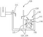
도 1은 본 발명에 따른 비점오염물질 저감시설을 나타낸 평면도이고,
도 2는 도 1의 A-A선을 따라 도시하여 본 발명에 따른 비점오염물질 저감시설의 흐름을 나타낸 도면이고,
도 3은 도 1의 B-B선을 따라 도시한 단면도이고,
도 4는 도 3에 도시된 필터부를 상세히 나타낸 도면이며, 그리고
도 5는 침전조내에 설치되는 유량조절장치의 상세도 및 작동상태를 나타낸 도면이다.1 is a plan view showing a non-point pollutant reducing facility according to the present invention,
2 is a view showing the flow of a non-point pollutant reducing facility according to the present invention shown along the line AA of Figure 1,
3 is a cross-sectional view taken along line BB of FIG. 1,
4 is a view showing in detail the filter unit shown in FIG.
5 is a view showing a detailed view and an operating state of the flow control device installed in the settling tank.
이하, 첨부된 도면을 참조하여 본 발명의 바람직한 실시 예를 상세하게 설명한다. 도면들 중 동일한 구성요소들은 가능한 어느 곳에서든지 동일한 부호로 표시한다. 또한 본 발명의 요지를 불필요하게 흐릴 수 있는 공지 기능 및 구성에 대한 상세한 설명은 생략한다.Hereinafter, preferred embodiments of the present invention will be described in detail with reference to the accompanying drawings. In the drawings, the same components are denoted by the same reference symbols whenever possible. In the following description, well-known functions or constructions are not described in detail since they would obscure the invention in unnecessary detail.
도 1은 본 발명에 따른 비점오염물질 저감시설을 나타낸 평면도이고, 도 2는 도 1의 A-A선을 따라 도시하여 본 발명 저감시설을 정면측에서 바라본 내부구조도이다.1 is a plan view showing a non-point pollutant reducing facility according to the present invention, Figure 2 is an internal structural view of the present invention in accordance with the line A-A of Figure 1 viewed from the front side.
도 1 및 도 2를 참고하면, 본 발명에 따른 비점오염물질 저감시설(100)은 어느 일측에 우수가 들어오도록 유입구(111)가 형성되어 있으면서 반대쪽 타측에 유입된 우수를 처리하여 배출시키는 배수구(112)가 형성되도록 커다란 함체 형상을 갖는 본체하우징(110)을 포함하여 구성된다.1 and 2, the non-point
이러한 본체하우징(110)은 도 1에서 보는 것과 같이, 우수의 흐름방향(본체하우징의 길이방향)을 따라 내부 공간을 구획하도록 두 개의 칸막이(113, 114)가 본체하우징(110)의 폭방향으로 형성되어 유입구(111)쪽에서부터 침전조(120), 분리조(150) 및 여과조(160)를 형성한다.As shown in FIG. 1, the
우선, 침전조(120)는 유입구(111)를 통해 들어온 우수가 침전되어 이물질들을 가라 앉히면서 우수에 포함되어 있는 이물질들을 필터링하여 필터링된 우수를 분리조(150)로 보내는 역할을 하게 된다. 이때, 침전조(120)는 침전된 우수를 1차적으로 필터링하기 위한 필터조(130)가 형성되며, 이 필터조(130)는 침전조(120)내에서 칸막이(113, 114)와 교차되는 방향으로 형성된 격벽(125)에 의해 분리되어 구성된다.
First, the
도 3은 침전조를 폭방향으로 단면하여 내부를 보인 도면이고, 도 4는 필터조내에 설치되어 있는 필터부를 상세히 나타낸 도면이다.3 is a view showing the inside of the sedimentation tank in the width direction, and FIG. 4 is a view showing the filter portion provided in the filter tank in detail.
도 3에서 보는 것과 같이 침전조(120)를 양쪽으로 분리한 격벽(125)에는 우수가 서로 유통되도록 제1월류로(126)가 형성된다. 이때, 제1월류로(126)는 유입구(111)보다는 낮게 형성됨이 당연할 것이다. 그리고 필터조(130)에는 유입된 우수를 1차로 필터링하는 필터부(140)가 설치된다.As shown in FIG. 3, the
필터부(140)는 도 3 및 도 4에서 보는 것과 같이, 제1월류로(126)의 하측에서 수평하게 설치되는 상판(141)과, 이 상판(141)의 중앙부에 하측으로 내려가도록 연장되는 다공통(142)과, 다공통(142)의 하부를 막는 하판(143)과, 다공통(142)에 끼워져 우수를 필터링하는 여재(144)와, 다공통(142)의 안쪽으로 삽입되는 걸름망(145)으로 구성된다. 따라서 상판(141)의 상부로 유입된 우수는 걸름망(145)과 여재(144)와 다공통(142)을 통과하여 필터조(130)내에 머무르다가 필터조(130)와 분리조(150)를 등분하고 있는 제1칸막이(113)에 형성되어 있는 제2월류로(136)를 타고 분리조(150)로 넘어가게 되는 것이다. 이때, 제2월류로(136)는 제1월류로(126)보다 더 낮으면서 필터조(130)의 바닥쪽으로 형성됨이 바람직하며, 필터조(130)에는 퇴적물이 쌓일 수 있으므로 바닥면보다는 조금 더 높게 형성됨이 좋을 것이다.As shown in FIGS. 3 and 4, the
여기에서, 다공통(142)은 다수의 통공들이 천공되어 있는 원형이나 사각형의 통이며, 이 다공통(142)은 안쪽과 바깥쪽에 이중으로 구성되어 있어 이 이중의 다공통(142)내에 여재(144)가 담기게 되는 것이다. 여재(144)는 시멘트 및 세골재에 기포가 발생되는 약품을 혼합하여 양생한 것으로, 경량이면서 투수성과 흡수성을 가지며 이물질이 여재(144)의 벽면에 들러 붙는 것이 억제되도록 제작된 것이다.Here, the
본 발명에 사용되는 여재(144)는 본 출원인 및 발명자에 의해 특허출원되어 등록받은 대한민국 등록특허공보 제10-1272626호(2013.06.03. 등록)에 개시된 것이 사용된다. 기존의 다른 투수성 여재는 골재들의 밀도에 따라 그 사이에 공극이 형성되도록 한 것인 반면, 본 발명에서 사용되는 여재는 거품이 나는 약품을 시멘트 및 세골재와 섞어 내부에 임의의 기공을 형성한 것으로, 미세한 기공에 의해 물이 흡수되도록 함으로서, 여재의 표면상에 이물질이 들러붙지 않게 된다.The
그리고 여재(144)의 내측면상에는 걸름망(145)을 더 배치하여 보다 큰 이물질 및 섬유질 등이 걸름망(145)에 걸려 주기적으로 걸름망(145)을 외부로 반출시켜 관리할 수도 있게 된다. 걸름망(145)에는 걸이구(146)를 달아 인출이 쉽게 할 수 있다.Further, on the inner side of the
본 발명에 따른 침전조(120) 및 필터조(130)의 바닥면은 도 3에서 보는 것과 같이 격벽(125)측을 향해 하향 경사지도록 구배(128, 138)를 주어 이 경사부에 침전된 이물질들이 퇴적되도록 하면서, 일정한 주기를 두어 퇴적된 이물질들을 퇴출구(129)를 통해 외부로 흡입 준설토록 할 수 있는 것이다.
The bottom surface of the
다시 도 1 및 도 2를 참고하면, 분리조(150)는 필터조(130)를 통해 들어온 우수에서 기름 등과 같은 유분을 제거하는 곳으로, 분리조(150)내에는 부력에 의해 물에 뜨는 유분흡착포(152)가 내장된다. 이러한 분리조(150)에는 유입된 우수가 월류될 수 있도록 월류벽(151)이 형성되고, 이 월류벽(151)의 상측으로 유분흡착포(152)가 배치된다. 유분흡착포(152)는 분리조(150)의 평면과 거의 일치하는 크기로 제작되어 분리조(150)내에 우수가 없더라도 월류벽(151)위에 걸쳐지도록 배치된다. 그리고 분리조(150)의 내측벽면상에는 월류벽(151)과 동일한 높이에 걸림턱(153)이 형성되어 유분흡착포(152)가 수평을 유지하면서 내려 앉거나 올라가도록 해준다.Referring again to FIGS. 1 and 2, the
이렇게 형성된 분리조(150)는 월류벽(151)을 넘으면서 우수에 포함되어 있는 유분들이 유분흡착포(152)에 흡수되고, 유분이 분리된 우수들은 제2칸막이(114)에 형성되어 있는 제3월류로(156)를 통해 여과조(160)로 유입된다.
The
여과조(160)는 시설(100)내로 유입된 우수를 최종적으로 여과시켜 배출시키는 곳으로, 여과조(160)의 폭방향으로 2개의 우회벽(161)이 형성되고, 이 우회벽(161)들이 지그재그로 연통되도록 하며, 이 우회벽(161)들의 사이에 여과필터(162)가 내장된다. 따라서 제3월류로(156)를 통해 유입된 우수는 지그재그 형태로 돌면서 다수의 여과필터(162)를 거치면서 여과되어 최종적으로 배출구(112)를 통해 외부로 배출되는 것이다.
The
이상과 같이 설명된 침전조(120), 필터조(130), 분리조(150) 및 여과조(160)는 우수에 포함되어 있는 비점오염원을 제거하기 위한 시설인 것인바, 지속적인 우수가 유입될때에는 비점오염원이 이미 제거된 우수라는 조건이 발생되므로, 굳이 필터조(130), 분리조(150) 및 여과조(160)를 거칠 필요가 없게 된다.The
도 5는 우수가 지속적으로 유입될때에 바이패스되는 흐름을 나타낸 도면이다.5 is a view showing a flow bypassed when rainwater is continuously introduced.
따라서 도 5에서 보는 것과 같이, 침전조(120)측의 제1칸막이(113)에 바이패스로(180)를 형성하고, 이 바이패스로(180)를 통해 배출구(112)측으로 다이랙트 통하도록 구성될 수도 있다. 즉, 바이패스로(180)는 제1칸막이(113)에 제1월류로(126)보다 더 높게(물론, 유입구보다는 낮게) 형성하고, 분리조(150) 및 여과조(160)의 뒤쪽으로 유도로(181)를 형성하여 배출구(112)와 통하도록 하는 것이다. 따라서 비점오염원이 높은 초기 우수는 제1월류로(126)를 넘나 들 정도의 중, 소량일 경우만 필터조(130) 및 여과조(160)를 통해 처리하여 배출시키고, 필터조(130) 및 여과조(160)를 통해 처리되는 양보다 더 많은 양의 우수가 유입되어 제1월류로(126)보다 더 높은 수위를 갖게 되면, 바이패스로(180)를 통해 직접 배출구(112)로 향하도록 유도하는 것이다.Therefore, as shown in FIG. 5, the
하지만, 필터조(130)내의 우수에는 필터부(140)에 의해 아직 필터링 되지 않은 이물질들이 포함되어 있게 되는데, 침전조(120)에서 바이패스로(180)를 통해 우수가 배출되면, 그 배수압에 의해 필터조(140)내의 우수가 역류하여 이물질이 포함된 우수가 그대로 배수될 수도 있는 문제가 발생될 수 있다. 따라서 본 발명에서는 제1월류로(126)에 침전조(120)의 수위에 따라 수문이 열고 닫히는 장치를 마련하여 침전조(120)의 수위가 높아 바이패스될때에는 제1월류로(126)가 닫혀 역류되는 것을 방지할 수 있도록 구성하였다.
However, the rainwater in the
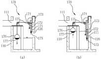
도 6은 침전조내에 설치된 유량조절장치를 나타낸 도면 및 이의 작동상태를 나타낸 도면이다.6 is a view showing a flow control device installed in the sedimentation tank and the operation state thereof.
도 6을 참고하면, 제1월류로(126)의 침전조(120)측 벽면상에 상,하로 슬라이딩 가능하도록 수문(171)을 설치하고, 이 수문(171)이 와이어(174)에 의해 승하강되도록 하였다. 그리고 와이어(174)는 이웃한 2개의 롤러(175)를 통해 침전조(120)측에서 잡아당기면 수문이 올라가 열리고, 침전조(120)측에서 와이어(174)를 놓으면 수문이 내려가 닫히도록 구성하였다.Referring to FIG. 6, the
이와 같은 수문(171) 작동을 위해 침전조(120)측에 부력재(176)를 띄우고, 부력재(176)에는 수문보다 더 무거워질 수 있도록 무게추(177)를 달아서 사용하게 된다. 따라서 침전조(120)에 우수가 없을때에는 도 6의 (a)도면과 같이, 부력재(176)가 무게추(177)에 의해 하강하면서 수문(171)을 들어올려 제1월류로(126)가 열려지도록 하고, 침전조(120)에 일정수위 이상의 우수가 차이면 도 6의 (b)도면과 같이, 부력재(176)가 떠 오르면서 수문(171)이 점차 하강하여 제1월류로(126)를 닫아주게 하는 것이다. 이처럼 부력재(176)가 올라가 수문(171)을 닫는 시점이 바이패스로(180)를 통해 우수가 배출되는 시점과 일치될 정도일 것이다.Floating
본 발명에 따른 수문(171)은 격벽(125)에서 수직하게 연장되는 슬라이딩샤프트(172)를 통해 승하강이 이루어지는데, 이 슬라이딩샤프트(172)의 상단측 및 하단측에는 수문(171)의 최저하향위치 및 최대상향위치를 결정하는 스토퍼(173)가 형성된다.The
상기와 같은 비점오염물질 저감시설은 위에서 설명된 실시 예들의 구성과 작동 방식에 한정되는 것이 아니다. 상기 실시 예들은 각 실시 예들의 전부 또는 일부가 선택적으로 조합되어 다양한 변형이 이루어질 수 있도록 구성될 수도 있다.
The non-point pollutant reduction facility as described above is not limited to the configuration and operation of the embodiments described above. The embodiments may be configured so that all or some of the embodiments may be selectively combined so that various modifications may be made.
100 : 비점오염물질 저감시설
110 : 본체하우징111 : 유입구
112 : 배출구113, 114 : 칸막이
120 : 침전조125 : 격벽
126 : 제1월류로130 : 필터조
135 : 격벽136 : 제2월류로
128, 138 : 구배129 : 퇴출구
140 : 필터부141 : 상판
142 : 다공판143 : 하판
144 : 여재145 : 걸름망
146 : 걸이구150 : 분리조
151 : 월류벽152 : 유분흡착포
153 : 걸림턱156 : 제3월류로
160 : 여과조161 : 우회벽
162 : 여과필터170 : 유량조절장치
171 : 수문172 : 슬라이딩샤프트
173 : 스토퍼174 : 와이어
175 : 롤러176 : 부력재
177 : 무게추180 : 바이패스로
181 : 유도로100: nonpoint pollutant reduction facility
110: main body housing 111: inlet
112
120: sedimentation tank 125: partition
126: first month flow 130: filter tank
135: bulkhead 136: second month flow
128, 138: gradient 129: exit
140: filter unit 141: top plate
142: porous plate 143: lower plate
144: Media 145: strainer
146: hook 150: separation tank
151: wall overflow 152: oil absorption cloth
153: jam jaw 156: third month flow
160: filtration tank 161: bypass wall
162: filtration filter 170: flow control device
171: sluice 172: sliding shaft
173: stopper 174: wire
175: roller 176: buoyancy material
177: Weight 180: Bypass
181: taxiway
Claims (6)
Translated fromKorean상기 본체하우징(110)내에 복수개의 칸막이(113, 114)가 형성되어 상기 유입구(111)측에서부터 배출구(112)쪽으로 분할된 공간을 형성하는 침전조(120), 분리조(150) 및 여과조(160);
상기 침전조(120)는 다시 격벽(125)이 형성되어 분할된 공간을 형성하는 필터조(130);
상기 격벽(125)과 칸막이들(113, 114)에 형성되어 차례로 물이 흘러 월류하도록 하는 제1월류로(126), 제2월류로(136) 및 제3월류로(156);
상기 필터조(130)내에 설치되어 유입된 유수가 통과하도록 하여 1차여과시키는 투수성/흡수성 여재를 갖는 필터부(140);
상기 분리조(150)내에서 우수에 뜨도록 배치되어 우수에 포함된 유분을 분리하는 유분흡착포(152);
상기 여과조(160)내에서 우수가 지그재그로 우회하도록 복수개의 우회벽(161)이 형성되며, 이 우회벽(161)들의 사이에 우수를 2차여과시키도록 설치되는 여과필터(162); 및
상기 침전조(120)측 칸막이(113)에 형성되어 유입되는 우수의 수위가 상기 제1월류로(126)보다 높을 경우 상기 분리조(150) 및 여과조(160)의 뒤쪽에 형성된 유도로(181)를 따라 상기 배출구(112)로 바로 연결되는 바이패스로(180);를 포함함을 특징으로 하는 비점오염물질 저감시설.
An inlet 111 is formed so that rainwater enters to one side, the main body housing 110 having a discharge port 112 formed on the other side so that the rainwater is processed and discharged;
A plurality of partitions 113 and 114 are formed in the main body housing 110 to form a space divided from the inlet 111 side to the outlet 112 toward the sedimentation tank 120, the separation tank 150, and the filtration tank 160. );
The settling tank 120 is a filter tank 130 to form a partitioned partition wall 125 is formed again;
First and second flow passages 126, second moon flow passages 136, and third moon flow passages 156 formed on the partition walls 125 and the partitions 113 and 114 so that water flows in turn and flows in turn;
A filter unit 140 installed in the filter tank 130 and having a water permeable / absorbent filter to firstly filter the flowing water flowing therethrough;
An oil adsorption cloth 152 disposed to float in rainwater in the separation tank 150 to separate oil contained in rainwater;
A plurality of bypass walls 161 are formed in the filtration tank 160 to divert rainwater zigzag, and a filtration filter 162 installed to secondary filter rainwater between the bypass walls 161; And
Induction furnace 181 formed at the rear of the separation tank 150 and the filtration tank 160 when the rainwater level formed in the partition 113 of the sedimentation tank 120 is higher than the first moon flow passage 126. A non-point pollutant reduction facility comprising: a bypass passage (180) directly connected to the outlet (112) along.
상기 침전조(120)에는 유입된 우수가 바이패스될때에 상기 제1월류로(126)를 폐쇄하도록 수문(171)을 갖는 유량조절장치(170)가 설치됨을 특징으로 하는 비점오염물질 저감시설.
The method of claim 1,
The sedimentation tank 120 is a non-point pollutant reduction facility, characterized in that the flow control device 170 having a water gate 171 is installed so as to close the first moon flow passage 126 when the rainwater is introduced into the bypass.
상기 유량조절장치(170)는 상기 수문(171)에 와이어(174)의 일단이 연결되어 상기 와이어(174)의 타단이 복수개의 롤러(175)를 통해 상기 침전조(120)에 배치된 부력재(176)로 연결되며, 상기 부력재(176)에는 상기 수문(171)을 들어올릴 수 있을 정도의 무게추(177)가 부착됨을 특징으로 하는 비점오염물질 저감시설.
3. The method of claim 2,
The flow control device 170 is one end of the wire 174 is connected to the water gate 171, the other end of the wire 174 buoyancy material 176 disposed in the settling tank 120 through a plurality of rollers 175 And the buoyancy material 176 is attached to the non-point pollutants, characterized in that the weight 177 is attached to the weight enough to lift the water gate 171.
상기 필터부(140)는 상기 필터조(130)의 제1월류로(126) 하측에서 가로방향으로 배치되는 상판(141)과, 상기 상판(141)의 중앙부에서 하측으로 연장되며 이중벽 구조를 갖는 다공통(142)과, 상기 다공통(142)의 하부를 밀폐시키는 하판(143)과, 상기 다공통(142)의 이중벽 사이로 삽입되는 경량 투수성/흡수성 여재(144)와, 상기 다공통(142)의 내측에 삽입되는 걸름망(145)를 포함하여 구성됨을 특징으로 하는 비점오염물질 저감시설.
The method according to claim 1 or 3,
The filter unit 140 has an upper plate 141 disposed in a transverse direction from the lower side of the first wall flow passage 126 of the filter tank 130, and extends downward from a central portion of the upper plate 141 and has a double wall structure. A porous cylinder 142, a lower plate 143 for sealing the lower portion of the porous cylinder 142, a light-permeable / absorbent media 144 inserted between the double wall of the porous cylinder 142, and the porous cylinder ( Non-point pollutant reduction facilities, characterized in that it comprises a filter net 145 is inserted into the inside of the 142.
상기 분리조(150)내에는 우수가 역류됨을 방지하는 월류벽(151)이 형성되며, 상기 유분흡착포(152)는 상기 월류벽(151)의 상측에 배치되고, 상기 월류벽(151)과 같은 높이의 분리조(150)내면상에는 상기 유분흡착포(152)가 수평을 유지하도록 하는 걸림턱(153)이 형성됨을 특징으로 하는 비점오염물질 저감시설.
5. The method of claim 4,
The overflow wall 151 is formed in the separation tank 150 to prevent rainwater from flowing backward. The oil adsorption cloth 152 is disposed above the overflow wall 151, and the same as the overflow wall 151. Non-point pollutant reduction facilities, characterized in that the locking jaw 153 is formed on the inner surface of the separation tank 150 to maintain the oil adsorption cloth 152 horizontal.
상기 침전조(120) 및 필터조(130)의 바닥면은 상기 격벽(125)측으로 경사지게 구배(128, 138)가 형성되어 이물질들이 퇴적되도록 하여 퇴출구(129)를 통하여 흡입 준설토록함을 특징으로 하는 비점오염물질 저감시설.
The method of claim 1,
The bottom surface of the sedimentation tank 120 and the filter tank 130 has a gradient (128, 138) is formed to be inclined toward the partition wall 125 so that foreign matters are deposited so that the dredging through the outlet (129). Non-point pollutant abatement facility.
Priority Applications (1)
| Application Number | Priority Date | Filing Date | Title |
|---|---|---|---|
| KR1020130089626AKR101334884B1 (en) | 2013-07-29 | 2013-07-29 | An apparatus for decreasing non-point source pollutant |
Applications Claiming Priority (1)
| Application Number | Priority Date | Filing Date | Title |
|---|---|---|---|
| KR1020130089626AKR101334884B1 (en) | 2013-07-29 | 2013-07-29 | An apparatus for decreasing non-point source pollutant |
Publications (1)
| Publication Number | Publication Date |
|---|---|
| KR101334884B1true KR101334884B1 (en) | 2013-11-29 |
Family
ID=49858843
Family Applications (1)
| Application Number | Title | Priority Date | Filing Date |
|---|---|---|---|
| KR1020130089626AExpired - Fee RelatedKR101334884B1 (en) | 2013-07-29 | 2013-07-29 | An apparatus for decreasing non-point source pollutant |
Country Status (1)
| Country | Link |
|---|---|
| KR (1) | KR101334884B1 (en) |
Cited By (6)
| Publication number | Priority date | Publication date | Assignee | Title |
|---|---|---|---|---|
| KR101656664B1 (en)* | 2015-12-18 | 2016-09-12 | 한국건설기술연구원 | Cartridge modular infiltration trench preprocessing tank, filtration apparatus using the same and rainwater filtration method using the same |
| KR101700931B1 (en)* | 2015-12-15 | 2017-01-31 | 조성범 | apparatus for reducing non-point source contaminant having function of screen and filtering media washing |
| KR102124414B1 (en)* | 2019-01-22 | 2020-06-18 | (주)선진테크산업 | Nonpoint pollution treatment apparatus |
| CN111359982A (en)* | 2020-03-17 | 2020-07-03 | 宁海县宏瑞汽车部件有限公司 | Auto parts clean-up equipment |
| CN116951142A (en)* | 2023-09-19 | 2023-10-27 | 成都市和谐环保工程技术有限公司 | Air release valve for sedimentation tank air inlet pipe and air release method thereof |
| KR102617930B1 (en) | 2022-12-14 | 2023-12-26 | 김성중 | Infiltration type rainwater reservoir system having eco-friendly water permeable concrete composition with recycled aggregates |
Citations (3)
| Publication number | Priority date | Publication date | Assignee | Title |
|---|---|---|---|---|
| KR100706269B1 (en) | 2005-07-12 | 2007-04-12 | 주식회사 환경시설관리공사 | Non-point pollutant purification device for early rainfall runoff |
| KR100904177B1 (en) | 2008-08-25 | 2009-07-24 | (주)유성환경 | Device and method for purifying the first rainwater containing non-point source |
| KR101235008B1 (en) | 2012-05-04 | 2013-02-21 | 주식회사 그린텍 | Non point pollution reducing system |
- 2013
- 2013-07-29KRKR1020130089626Apatent/KR101334884B1/ennot_activeExpired - Fee Related
Patent Citations (3)
| Publication number | Priority date | Publication date | Assignee | Title |
|---|---|---|---|---|
| KR100706269B1 (en) | 2005-07-12 | 2007-04-12 | 주식회사 환경시설관리공사 | Non-point pollutant purification device for early rainfall runoff |
| KR100904177B1 (en) | 2008-08-25 | 2009-07-24 | (주)유성환경 | Device and method for purifying the first rainwater containing non-point source |
| KR101235008B1 (en) | 2012-05-04 | 2013-02-21 | 주식회사 그린텍 | Non point pollution reducing system |
Cited By (7)
| Publication number | Priority date | Publication date | Assignee | Title |
|---|---|---|---|---|
| KR101700931B1 (en)* | 2015-12-15 | 2017-01-31 | 조성범 | apparatus for reducing non-point source contaminant having function of screen and filtering media washing |
| KR101656664B1 (en)* | 2015-12-18 | 2016-09-12 | 한국건설기술연구원 | Cartridge modular infiltration trench preprocessing tank, filtration apparatus using the same and rainwater filtration method using the same |
| KR102124414B1 (en)* | 2019-01-22 | 2020-06-18 | (주)선진테크산업 | Nonpoint pollution treatment apparatus |
| CN111359982A (en)* | 2020-03-17 | 2020-07-03 | 宁海县宏瑞汽车部件有限公司 | Auto parts clean-up equipment |
| KR102617930B1 (en) | 2022-12-14 | 2023-12-26 | 김성중 | Infiltration type rainwater reservoir system having eco-friendly water permeable concrete composition with recycled aggregates |
| CN116951142A (en)* | 2023-09-19 | 2023-10-27 | 成都市和谐环保工程技术有限公司 | Air release valve for sedimentation tank air inlet pipe and air release method thereof |
| CN116951142B (en)* | 2023-09-19 | 2023-12-12 | 成都市和谐环保工程技术有限公司 | Air release valve for sedimentation tank air inlet pipe and air release method thereof |
Similar Documents
| Publication | Publication Date | Title |
|---|---|---|
| KR100894022B1 (en) | Non-point pollutant treatment device | |
| KR100911819B1 (en) | Nonpoint Pollutant Reduction Device | |
| KR101242275B1 (en) | Back washing type apparatus for disposing non-point pollution source using power | |
| KR101495675B1 (en) | Nonpoint pollution decrease apparatus and nonpoint pollution decrease material method | |
| KR101741449B1 (en) | Apparatus for treating rainwater and overflow water of confluent water drainage | |
| KR101334884B1 (en) | An apparatus for decreasing non-point source pollutant | |
| KR100904177B1 (en) | Device and method for purifying the first rainwater containing non-point source | |
| KR20100020867A (en) | Apparatus for removal of nonpoint source pollutant using slope filter | |
| KR101479462B1 (en) | Apparatus of reducing non-point source contaminants | |
| KR101781178B1 (en) | First rainwater treatment aparatus | |
| KR100787625B1 (en) | Pollution water purification device | |
| KR101244122B1 (en) | Back washing type apparatus for disposing non-point pollution source using floating decanter | |
| KR101207293B1 (en) | Water Treatment Facility for Underground Infiltration of Early Rainwater | |
| KR101912323B1 (en) | non-point source contaminant treatment apparatus using precipitation and filtering | |
| KR101186604B1 (en) | Non-point source contaminant treatment apparatus using activated-bio carrier | |
| KR101853617B1 (en) | The modular infiltration trench for easy maintenance | |
| KR100955098B1 (en) | Treatment apparatus for phosphorus removal from rain water | |
| KR101262194B1 (en) | Device for treating combined sewer overflows | |
| KR20090033680A (en) | Stormwater Treatment System and Stormwater Treatment Method | |
| KR101353280B1 (en) | Modular infiltration trench combined with filter cartridges | |
| KR100605267B1 (en) | Storm water treatment device | |
| KR100927631B1 (en) | Non-point pollutant reduction device using biofilm media | |
| KR20080102867A (en) | Sewage Overflow Water Treatment System | |
| KR101195091B1 (en) | Non-point Source Control Facility | |
| KR102139984B1 (en) | Filter replacable non-point pollution treatment ditch |
Legal Events
| Date | Code | Title | Description |
|---|---|---|---|
| A201 | Request for examination | ||
| PA0109 | Patent application | St.27 status event code:A-0-1-A10-A12-nap-PA0109 | |
| PA0201 | Request for examination | St.27 status event code:A-1-2-D10-D11-exm-PA0201 | |
| A302 | Request for accelerated examination | ||
| PA0302 | Request for accelerated examination | St.27 status event code:A-1-2-D10-D17-exm-PA0302 St.27 status event code:A-1-2-D10-D16-exm-PA0302 | |
| E701 | Decision to grant or registration of patent right | ||
| PE0701 | Decision of registration | St.27 status event code:A-1-2-D10-D22-exm-PE0701 | |
| GRNT | Written decision to grant | ||
| PR0701 | Registration of establishment | St.27 status event code:A-2-4-F10-F11-exm-PR0701 | |
| PR1002 | Payment of registration fee | St.27 status event code:A-2-2-U10-U11-oth-PR1002 Fee payment year number:1 | |
| PG1601 | Publication of registration | St.27 status event code:A-4-4-Q10-Q13-nap-PG1601 | |
| R18-X000 | Changes to party contact information recorded | St.27 status event code:A-5-5-R10-R18-oth-X000 | |
| P14-X000 | Amendment of ip right document requested | St.27 status event code:A-5-5-P10-P14-nap-X000 | |
| PN2301 | Change of applicant | St.27 status event code:A-5-5-R10-R13-asn-PN2301 St.27 status event code:A-5-5-R10-R11-asn-PN2301 | |
| P14-X000 | Amendment of ip right document requested | St.27 status event code:A-5-5-P10-P14-nap-X000 | |
| P16-X000 | Ip right document amended | St.27 status event code:A-5-5-P10-P16-nap-X000 | |
| Q16-X000 | A copy of ip right certificate issued | St.27 status event code:A-4-4-Q10-Q16-nap-X000 | |
| FPAY | Annual fee payment | Payment date:20161124 Year of fee payment:4 | |
| PR1001 | Payment of annual fee | St.27 status event code:A-4-4-U10-U11-oth-PR1001 Fee payment year number:4 | |
| P22-X000 | Classification modified | St.27 status event code:A-4-4-P10-P22-nap-X000 | |
| FPAY | Annual fee payment | Payment date:20171016 Year of fee payment:5 | |
| PR1001 | Payment of annual fee | St.27 status event code:A-4-4-U10-U11-oth-PR1001 Fee payment year number:5 | |
| PN2301 | Change of applicant | St.27 status event code:A-5-5-R10-R13-asn-PN2301 St.27 status event code:A-5-5-R10-R11-asn-PN2301 | |
| FPAY | Annual fee payment | Payment date:20181126 Year of fee payment:6 | |
| PR1001 | Payment of annual fee | St.27 status event code:A-4-4-U10-U11-oth-PR1001 Fee payment year number:6 | |
| FPAY | Annual fee payment | Payment date:20191114 Year of fee payment:7 | |
| PR1001 | Payment of annual fee | St.27 status event code:A-4-4-U10-U11-oth-PR1001 Fee payment year number:7 | |
| PR1001 | Payment of annual fee | St.27 status event code:A-4-4-U10-U11-oth-PR1001 Fee payment year number:8 | |
| PR1001 | Payment of annual fee | St.27 status event code:A-4-4-U10-U11-oth-PR1001 Fee payment year number:9 | |
| PC1903 | Unpaid annual fee | St.27 status event code:A-4-4-U10-U13-oth-PC1903 Not in force date:20221126 Payment event data comment text:Termination Category : DEFAULT_OF_REGISTRATION_FEE | |
| PN2301 | Change of applicant | St.27 status event code:A-5-5-R10-R11-asn-PN2301 | |
| PN2301 | Change of applicant | St.27 status event code:A-5-5-R10-R14-asn-PN2301 | |
| PC1903 | Unpaid annual fee | St.27 status event code:N-4-6-H10-H13-oth-PC1903 Ip right cessation event data comment text:Termination Category : DEFAULT_OF_REGISTRATION_FEE Not in force date:20221126 |