KR101333913B1 - Square Lithium Battery Roll Structure - Google Patents
Square Lithium Battery Roll StructureDownload PDFInfo
- Publication number
- KR101333913B1 KR101333913B1KR1020120007369AKR20120007369AKR101333913B1KR 101333913 B1KR101333913 B1KR 101333913B1KR 1020120007369 AKR1020120007369 AKR 1020120007369AKR 20120007369 AKR20120007369 AKR 20120007369AKR 101333913 B1KR101333913 B1KR 101333913B1
- Authority
- KR
- South Korea
- Prior art keywords
- tab
- lithium battery
- roll structure
- battery roll
- electrode plate
- Prior art date
- Legal status (The legal status is an assumption and is not a legal conclusion. Google has not performed a legal analysis and makes no representation as to the accuracy of the status listed.)
- Expired - Fee Related
Links
Images


Classifications
- H—ELECTRICITY
- H01—ELECTRIC ELEMENTS
- H01M—PROCESSES OR MEANS, e.g. BATTERIES, FOR THE DIRECT CONVERSION OF CHEMICAL ENERGY INTO ELECTRICAL ENERGY
- H01M50/00—Constructional details or processes of manufacture of the non-active parts of electrochemical cells other than fuel cells, e.g. hybrid cells
- H01M50/10—Primary casings; Jackets or wrappings
- H01M50/102—Primary casings; Jackets or wrappings characterised by their shape or physical structure
- H01M50/103—Primary casings; Jackets or wrappings characterised by their shape or physical structure prismatic or rectangular
- H—ELECTRICITY
- H01—ELECTRIC ELEMENTS
- H01M—PROCESSES OR MEANS, e.g. BATTERIES, FOR THE DIRECT CONVERSION OF CHEMICAL ENERGY INTO ELECTRICAL ENERGY
- H01M50/00—Constructional details or processes of manufacture of the non-active parts of electrochemical cells other than fuel cells, e.g. hybrid cells
- H01M50/50—Current conducting connections for cells or batteries
- H01M50/531—Electrode connections inside a battery casing
- H—ELECTRICITY
- H01—ELECTRIC ELEMENTS
- H01M—PROCESSES OR MEANS, e.g. BATTERIES, FOR THE DIRECT CONVERSION OF CHEMICAL ENERGY INTO ELECTRICAL ENERGY
- H01M50/00—Constructional details or processes of manufacture of the non-active parts of electrochemical cells other than fuel cells, e.g. hybrid cells
- H01M50/50—Current conducting connections for cells or batteries
- H01M50/543—Terminals
- H—ELECTRICITY
- H01—ELECTRIC ELEMENTS
- H01M—PROCESSES OR MEANS, e.g. BATTERIES, FOR THE DIRECT CONVERSION OF CHEMICAL ENERGY INTO ELECTRICAL ENERGY
- H01M2220/00—Batteries for particular applications
- H01M2220/30—Batteries in portable systems, e.g. mobile phone, laptop
- Y—GENERAL TAGGING OF NEW TECHNOLOGICAL DEVELOPMENTS; GENERAL TAGGING OF CROSS-SECTIONAL TECHNOLOGIES SPANNING OVER SEVERAL SECTIONS OF THE IPC; TECHNICAL SUBJECTS COVERED BY FORMER USPC CROSS-REFERENCE ART COLLECTIONS [XRACs] AND DIGESTS
- Y02—TECHNOLOGIES OR APPLICATIONS FOR MITIGATION OR ADAPTATION AGAINST CLIMATE CHANGE
- Y02E—REDUCTION OF GREENHOUSE GAS [GHG] EMISSIONS, RELATED TO ENERGY GENERATION, TRANSMISSION OR DISTRIBUTION
- Y02E60/00—Enabling technologies; Technologies with a potential or indirect contribution to GHG emissions mitigation
- Y02E60/10—Energy storage using batteries
Landscapes
- Chemical & Material Sciences (AREA)
- Chemical Kinetics & Catalysis (AREA)
- Electrochemistry (AREA)
- General Chemical & Material Sciences (AREA)
- Connection Of Batteries Or Terminals (AREA)
Abstract
Translated fromKoreanDescription
Translated fromKorean본 발명은 각형 리튬형 전지롤 구조체에 관한 것으로, 더욱 상세하게는 각형 이차전지의 케이스에 내장되는 각형 리튬형 전지롤 구조체에 관한 것이다.The present invention relates to a square lithium battery roll structure, and more particularly, to a square lithium battery roll structure embedded in a case of a square secondary battery.
통상적으로, 충방전이 가능한 이차전지는 셀룰러폰, 노트북 컴퓨터, 캠코더 등 휴대용 전자기기의 개발로 활발한 연구가 진행 중이며, 이 중에서 리튬 이차전지는 작동전압이 약 3.6V 정도로서, 휴대용 전자기기의 전원으로 많이 사용되고 있는 니켈-카드뮴 전지나 니켈-메탈 하이드라이드 전지에 비하여 성능이 3배 이상 우수하고, 단위 중량당 에너지밀도의 특성도 우수하여 그 이용 및 연구가 급속도로 신장되고 있다.In general, the rechargeable battery capable of charging and discharging is being actively researched by the development of portable electronic devices such as cellular phones, notebook computers, camcorders, etc. Among these, the lithium secondary battery has an operating voltage of about 3.6V, which is used as a power source for portable electronic devices. Compared to nickel-cadmium batteries and nickel-metal hydride batteries which are widely used, the performance is three times or more, and the energy density per unit weight is also excellent, and the use and research thereof are rapidly expanding.
리튬 이차전지는 전해액의 종류에 따라 액체 전해질 전지와, 고분자 전해질 전지로 분류할 수 있다. 일반적으로는, 액체 전해질을 사용하는 전지를 리튬 이온전지라 하고, 고분자 전해질을 사용하는 전지를 리튬 폴리머 전지라고 한다. 리튬 이차전지는 다양한 형태로 제조 가능한데, 대표적인 형상으로는 리튬 이온전지에 주로 사용되는 원통형 및 각형을 들 수 있다. 최근 들어 각광받는 리튬 폴리머 전지는 유연성을 지닌 파우치형으로 제조되어서, 그 형상이 비교적 자유롭다. 또한, 안전성도 우수하고, 무게가 가벼워서 휴대용 전자기기의 슬림화 및 경량화에 유리하다.Lithium secondary batteries can be classified into liquid electrolyte batteries and polymer electrolyte batteries according to the type of electrolyte. Generally, a battery using a liquid electrolyte is called a lithium ion battery, and a battery using a polymer electrolyte is called a lithium polymer battery. The lithium secondary battery may be manufactured in various forms, and typical shapes include cylindrical and rectangular shapes mainly used in lithium ion batteries. Lithium polymer batteries, which are in the spotlight in recent years, are manufactured in a flexible pouch type, and their shapes are relatively free. In addition, it is excellent in safety and light in weight, which is advantageous for slimmer and lighter portable electronic devices.
근래에는 리튬 이차전지가 다양한 전자기기를 넘어 전기 자동차 등의 전원으로도 사용됨에 따라 리튬 이차 전지의 용량의 증가 및 안전성 등이 중요한 문제로 대두되고 있으며 이를 위한 연구가 활발히 진행되고 있다.Recently, as the lithium secondary battery is used as a power source for electric vehicles beyond various electronic devices, an increase in the capacity and safety of the lithium secondary battery has emerged as an important problem, and research for this is being actively conducted.
이에 리튬 이차전지의 용량을 증가시키기 위한 파우치형으로 제조된 단위 전지셀을 여러개 적층하고 전기적으로 연결하여 전지팩을 조립함으로써 요구되는 용량의 리튬 이차 전지를 제공하고 있다. 이러한 전지팩의 크기는 그 용도상 무한히 커질 수 없으며 되도록 가볍고 컴팩트하면서도 대용량일 것이 요구된다.Accordingly, to provide a lithium secondary battery having a required capacity by assembling a battery pack by stacking a plurality of unit battery cells made of a pouch type to increase the capacity of the lithium secondary battery and electrically connected. The size of such a battery pack cannot be infinitely large for its purpose, and it is required to be as light and compact as possible.
또한, 일정한 단위 면적을 갖는 전지팩에는 다수의 단위 전지셀들이 전기적으로 연결되어 있으므로 이들 단위 전지셀들 중 어느 하나에 발열 또는 쇼트 현상이 일어나는 경우, 전지팩이 폭발할 수 있는 위험이 있는 바, 이와 같은 위험을 낮추고 안전성을 향상시킨 전지팩에 대한 요구가 증대되고 있다.In addition, since a plurality of unit battery cells are electrically connected to a battery pack having a predetermined unit area, there is a risk that the battery pack may explode when heat or short occurs in any one of these unit battery cells. There is an increasing demand for battery packs that lower such risks and improve safety.
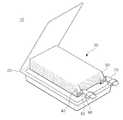
종래, 전지팩에 포함되는 단위 전지셀의 형상을 살펴보면 도 1과 같다. 도 1을 참조하면, 단위 전지셀(10)은 전극조립체(30)와, 상기 전극조립체(30)가 수용디는 공간부를 제공하는 케이스(20)를 포함하고 있으며, 상기 전극조립체(30)는 잘 알려진 대로, 양극판과, 음극판, 그 사이에 개재되는 세퍼레이터로 이루어져 있다. 상기 전극조립체(30)는 양극판, 세퍼레이터, 음극판 순으로 배치된 상태에서 젤리-롤형(Jelly-roll type)으로 와인딩되거나, 다수장이 적층형(Stack type)으로 라미테이팅되어 있다.Conventionally, the shape of a unit battery cell included in a battery pack is as shown in FIG. 1. Referring to FIG. 1, the
또한, 상기 전극조립체(30)는 각 극 판과 전기적으로 연결된 양극 리드(60)와, 음극 리드(70)가 밀봉된 케이스(20)의 외부로 노출되어 있다. 상기 케이스(20)는 전자기기의 경박단소화를 실현하기 위하여 후막의 금속판으로 성형한 원통형이나 각형과는 달리, 박막의 금속필름과, 그 양면에 절연성 필름이 부착되어 자유롭게 구부림이 가능한 파우치형(Pouched type)이다.In addition, the
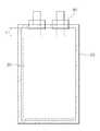
도 2에는 도 1의 이차전지에서 양극 탭들이 밀집된 형태로 결합되어 양극리드에 연결되어 있는 전지케이스 내부 상단의 부분 확대도가 도시되어 있고, 도 3에는 도 1의 이차전지를 조립한 상태의 정면 투시도가 도시되어 있다. 이들 도면을 참조하면, 전극조립체(30)의 양극 집전체(41)로부터 연장되어 돌출되어 있는 다수의 양극 탭들(40)은, 예를 들어 용접에 의해 일체로 결합된 용착부의 형태로 양극리드(60)에 연결되며, 용착부의 양극 탭들(40)은 대략 V자 형상으로 절곡되어 있어 전극 탭들과 전극리드이 결합 부위를 V-포밍(Forming) 부위로 칭하기도 한다. 상기 양극리드(60)는 양극 탭 용착부가 연결되어 있는 대향 단부(61)가 노출된 상태로 전지케이스(20)에 의해 밀봉된다.FIG. 2 is a partially enlarged view of an upper portion of a battery case connected to a cathode lead by combining positively connected tabs of the secondary battery of FIG. 1, and FIG. 3 is a front view of the assembled secondary battery of FIG. 1. Perspective view is shown. Referring to these drawings, the plurality of
그러나, 대용량의 전기를 발생시키기 위해서는 다수의 양극 집전체(41)가 구비되어야 하고, 상기 양극 집전체(41)의 양극 탭들(40)을 일체로 연결하기 위해 용착부를 형성하여야 하나, 용착부를 형성함으로 인해 전지케이스(20)의 내부 상단은 전극조립체(30)의 상단(또는 하단)면으로부터 일정한 거리만큼 이격되어 있고 이에 따라 전극조립체의 상단(또는 하단)면과 절연필름 사이의 거리(L1, L2)가 매우 크며, 전극 탭과 전극리드의 용착부 주변으로는 전지의 용량 등과는 무관한 사공간(Dead space)이고 또한 가스 등이 발생하는 경우 이곳에 고이는 문제점이 있었다.However, in order to generate a large amount of electricity, a plurality of positive electrode
또한, 상기 융착부의 양극 탭들(40)이 상부와 하부의 일측에서 압착되어 일측으로 절곡되는 형상을 가짐으로 인하여 압착되는 부위의 양극 탭들(40)이 변형이 심하고, 그로 인하여 변형이 심한 양극 탭들(40)의 절곡부위가 절단되는 문제점이 있었다.In addition, since the
본 발명은 복수개의 양극 전극판과 음극 전극판 및 분리막이 적층되어 형성된 제1각형 리튬형 전지롤 구조체와 제2각형 리튬형 전지롤 구조체의 일단에 각각 형성된 제1탭과 제2탭 및 제3탭과 제4탭을 제1단자 케이스와 제2단자 케이스에 삽입하고, 제1단자 케이스와 제2단자 케이스를 일측에 접지부가 형성된 터미널과 연결하는 각형 리튬형 전지롤 구조체를 제공하는데 그 목적이 있다.According to the present invention, a first tab, a second tab, and a third tab are respectively formed at one end of a first lithium lithium battery roll structure and a second lithium lithium battery roll structure formed by stacking a plurality of positive electrode plates, a negative electrode plate, and a separator. The purpose of the present invention is to provide a rectangular lithium battery roll structure in which a tab and a fourth tab are inserted into a first terminal case and a second terminal case, and the first terminal case and the second terminal case are connected to a terminal having a ground portion at one side thereof. have.
본 발명은, 일단에 제1탭이 형성된 복수개의 양극 전극판과, 일단에 제2탭이 형성된 복수개의 음극 전극판이 순차적으로 적층되며, 상기 양극 전극판과 상기 음극 전극판 사이에는 복수개의 분리막이 위치되며, 복수개의 상기 제1탭과 상기 제2탭을 포밍하여 제작된 제1각형 리튬형 전지롤 구조체; 상기 제1각형 리튬형 전지롤 구조체의 일단 양측에 형성된 제1탭 압착부 및 제2탭 압착부에 끼워지는 제1단자 케이스; 일단에 제3탭이 형성된 복수개의 양극 전극판과, 일단에 제4탭이 형성된 복수개의 음극 전극판이 순차적으로 적층되며, 상기 양극 전극판과 상기 음극 전극판 사이에는 복수개의 분리막이 위치되며, 복수개의 상기 제3탭과 상기 제4탭을 포밍하여 제작되며, 상기 제1각형 리튬형 전지롤 구조체의 상부에 위치하는 제2각형 리튬형 전지롤 구조체; 상기 제2각형 리튬형 전지롤 구조체의 일단 양측에 형성된 제3탭 압착부 및 제4탭 압착부에 끼워지는 제2단자 케이스; 및 이격된 상기 제1단자 케이스와 상기 제2단자 케이스를 연결하는 터미널을 포함하며, 상기 제1단자 케이스와 상기 제2단자 케이스는 상기 제1탭 압착부 내지 제4탭 압착부가 삽입되는 삽입부와, 상기 삽입부의 중앙부에서 일측으로 돌출되는 돌출부로 이루어지고, 상기 돌출부에는 체결수단이 삽입되는 단자체결홀이 형성되는 각형 리튬형 전지롤 구조체를 제공한다.According to the present invention, a plurality of cathode electrode plates having a first tab formed at one end thereof and a plurality of cathode electrode plates having a second tab formed at one end thereof are sequentially stacked, and a plurality of separators are disposed between the anode electrode plate and the cathode electrode plate. A first prismatic lithium battery roll structure positioned and formed by forming a plurality of the first tab and the second tab; A first terminal case fitted to a first tab pressing part and a second tab pressing part formed at both ends of one end of the first prismatic lithium battery roll structure; A plurality of cathode electrode plates having a third tab formed at one end and a plurality of cathode electrode plates having a fourth tab formed at one end thereof are sequentially stacked, and a plurality of separators are positioned between the anode electrode plate and the cathode electrode plate. A second prismatic lithium battery roll structure formed by forming three third tabs and the fourth tabs and positioned on an upper portion of the first prismatic lithium battery roll structure; A second terminal case fitted to a third tab pressing part and a fourth tab pressing part formed at both ends of one end of the second prismatic lithium battery roll structure; And a terminal connecting the first terminal case and the second terminal case spaced apart from each other, wherein the first terminal case and the second terminal case are inserted into the first tab pressing part and the fourth tab pressing part. And, provided with a protruding portion protruding to one side from the center portion of the insertion portion, the protruding portion provides a rectangular lithium battery roll structure is formed with a terminal fastening hole is inserted into the fastening means.
본 발명에 따른 각형 리튬형 전지롤 구조체에 있어서, 상기 터미널은 사각형상의 형상의 몸체를 가질 수 있고, 상기 몸체에는 상기 체결수단이 관통하는 관통홀이 형성될 수 있으며, 상기 몸체의 일단에는 접지부가 형성될 수 있다.In the prismatic lithium battery roll structure according to the present invention, the terminal may have a body having a rectangular shape, and the body may be formed with a through hole through which the fastening means passes, and one end of the body may have a ground portion. Can be formed.
또한, 상기 제1각형 리튬형 전지롤 구조체는 상기 양극 전극판과 상기 음극 전극판을 적층 시에 상기 양극 전극판의 일단에 형성된 제1탭과 상기 음극 전극판의 일단에 형성된 제2탭이 수평선상으로 이격되게 형성될 수 있고, 상기 제2각형 리튬형 전지롤 구조체는 상기 양극 전극판과 상기 음극 전극판을 적층 시에 상기 양극 전극판의 일단에 형성된 제3탭과 상기 음극 전극판의 일단에 형성된 제4탭이 수평선상으로 이격되게 형성될 수 있으며, 상기 제1각형 리튬형 전지롤 구조체의 제1탭 및 제2탭의 포밍과, 상기 제2각형 리튬형 전지롤 구조체의 제3탭 및 제4탭의 포밍은 리벳과 압착수단을 이용하여 상기 제1탭 내지 제4탭의 상부와 하부에서 균등하게 압착할 수 있다.In addition, the first prismatic lithium battery roll structure has a first tab formed at one end of the positive electrode plate and a second tab formed at one end of the negative electrode plate when the positive electrode plate and the negative electrode plate are stacked. The second rectangular lithium battery roll structure may be formed to be spaced apart from each other, and the second tabular lithium battery roll structure may include a third tab formed at one end of the anode electrode plate and one end of the cathode electrode plate when the cathode electrode plate and the cathode electrode plate are laminated. The fourth tabs formed on the second tabs may be spaced apart from each other on a horizontal line, and the first tabs and the second tabs of the first prismatic lithium battery roll structure and the third tabs of the second prismatic lithium battery roll structure And the forming of the fourth tab may be equally compressed at the upper and lower portions of the first to fourth tabs using rivets and the pressing means.
본 발명에 따른 각형 리튬형 전지롤 구조체는 복수개의 양극 전극판과 음극 전극판 및 분리막으로 형성된 제1각형 리튬형 전지롤 구조체와 제2각형 리튬형 전지롤 구조체를 병렬로 연결하여 대용량의 전기를 생성할 수 있다.The prismatic lithium battery roll structure according to the present invention connects the first prismatic lithium battery roll structure and the second prismatic lithium battery roll structure formed of a plurality of positive electrode plates, negative electrode plates, and separators in parallel to generate a large amount of electricity. Can be generated.
도 1은 종래 파우치형 이차전지의 일반적인 구조를 도시한 분해 사시도이다.
도 2는 도 1의 이차전지에서 양극 탭들이 밀집된 형태로 결합되어 양극리드에 연결되어 있는 전지케이스 내부 상단의 부분 확대도이다.
도 3은 도 1의 이차전지를 조립한 상태의 정면 투시도이다.
도 4는 본 발명에 따른 각형 리튬형 전지롤 구조체를 도시한 도면이다.
도 5는 도 4에 도시된 제1각형 리튬형 전지롤 구조체를 제작하는 과정을 도시한 도면이다.
도 6은 도 4에 도시된 제2각형 리튬형 전지롤 구조체를 제작하는 과정을 도시한 도면이다.
도 7은 도 5를 통해 제작된 제1각형 리튬형 전지롤 구조체에 제1단자 케이스를 체결하는 상태를 도시한 도면이다.
도 8은 제1단자 케이스와 제2단자 케이스가 체결된 제1각형 리튬형 전지롤 케이스와 제2각형 리튬형 전지롤 케이스를 적층시키는 상태를 도시한 도면이다.
도 9는 제1단자 케이스와 제2단자 케이스에 터미널을 장착하는 상태를 도시한 도면이다.
도 10은 도 4와 도 5에 도시된 리벳을 도시한 도면이다.1 is an exploded perspective view illustrating a general structure of a conventional pouch type secondary battery.
FIG. 2 is a partially enlarged view of an upper portion of an inside of a battery case in which the positive electrode tabs are densely coupled in the secondary battery of FIG. 1 and connected to the positive electrode lead.
3 is a front perspective view of a state in which the secondary battery of FIG. 1 is assembled.
4 is a view showing a rectangular lithium battery roll structure according to the present invention.
FIG. 5 is a view illustrating a process of manufacturing the first prismatic lithium battery roll structure shown in FIG. 4.
FIG. 6 is a view illustrating a process of manufacturing the second prismatic lithium battery roll structure shown in FIG. 4.
FIG. 7 is a view illustrating a state in which the first terminal case is fastened to the first prismatic lithium battery roll structure manufactured through FIG. 5.
FIG. 8 is a view illustrating a state in which the first prismatic lithium battery roll case and the second prismatic lithium battery roll case in which the first terminal case and the second terminal case are fastened are stacked.
9 is a diagram illustrating a state in which terminals are mounted on a first terminal case and a second terminal case.
FIG. 10 is a view showing the rivets shown in FIGS. 4 and 5.
이하, 첨부된 도면을 참조하여 본 발명에 따른 바람직한 실시 예를 상세히 설명하기로 한다. 이에 앞서, 본 명세서 및 청구범위에 사용된 용어나 단어는 통상적이거나 사전적인 의미로 한정해서 해석되어서는 아니 되며, 발명자는 그 자신의 발명을 가장 최선의 방법으로 설명하기 위해 용어의 개념을 적절하게 정의할 수 있다는 원칙에 입각하여, 본 발명의 기술적 사상에 부합하는 의미와 개념으로 해석되어야만 한다.Hereinafter, preferred embodiments of the present invention will be described in detail with reference to the accompanying drawings. Prior to this, terms and words used in the present specification and claims should not be construed as limited to ordinary or dictionary terms, and the inventor should appropriately interpret the concepts of the terms appropriately The present invention should be construed in accordance with the meaning and concept consistent with the technical idea of the present invention.
따라서 본 명세서에 기재된 실시 예와 도면에 도시된 구성은 본 발명의 가장 바람직한 일 실시 예에 불과할 뿐이고, 본 발명의 기술적 사상을 모두 대변하는 것은 아니므로, 본 출원시점에 있어서 이들을 대체할 수 있는 균등한 변형 예들이 있을 수 있음을 이해하여야 한다.Therefore, the embodiments described in the present specification and the configurations shown in the drawings are merely the most preferred embodiments of the present invention and are not intended to represent all of the technical ideas of the present invention. Therefore, It should be understood that there may be variations.
도 4는 본 발명에 따른 각형 리튬형 전지롤 구조체를 도시한 도면이고, 도 5는 도 4에 도시된 제1각형 리튬형 전지롤 구조체를 제작하는 과정을 도시한 도면이며, 도 6은 도 4에 도시된 제2각형 리튬형 전지롤 구조체를 제작하는 과정을 도시한 도면이고, 도 7은 도 5를 통해 제작된 제1각형 리튬형 전지롤 구조체에 제1단자 케이스를 체결하는 상태를 도시한 도면이며, 도 8은 제1단자 케이스와 제2단자 케이스가 체결된 제1각형 리튬형 전지롤 케이스와 제2각형 리튬형 전지롤 케이스를 적층시키는 상태를 도시한 도면이고, 도 9는 제1단자 케이스와 제2단자 케이스에 터미널을 장착하는 상태를 도시한 도면이며, 도 10은 도 4와 도 5에 도시된 리벳을 도시한 도면이다.4 is a view illustrating a rectangular lithium battery roll structure according to the present invention, FIG. 5 is a view illustrating a process of manufacturing a first lithium lithium battery roll structure shown in FIG. 4, and FIG. 6 is FIG. 4. FIG. 7 is a view illustrating a process of manufacturing the second prismatic lithium battery roll structure illustrated in FIG. 7, and FIG. 7 illustrates a state in which the first terminal case is fastened to the first prismatic lithium battery roll structure manufactured through FIG. FIG. 8 is a view illustrating a state in which a first prismatic lithium battery roll case and a second prismatic lithium battery roll case in which a first terminal case and a second terminal case are fastened, are stacked, and FIG. FIG. 10 is a view illustrating a terminal mounted on a terminal case and a second terminal case, and FIG. 10 is a view illustrating the rivets shown in FIGS. 4 and 5.
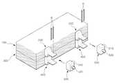
도 4 내지 도 10을 참조하면, 본 발명에 따른 각형 리튬형 전지롤 구조체는, 제1각형 리튬형 전지롤 구조체(100)와, 제1단자 케이스(200)와, 제2각형 리튬형 전지롤 케이스(300)와, 제2단자 케이스(400)와, 터미널(500)를 포함한다.4 to 10, the prismatic lithium battery roll structure according to the present invention includes a first prismatic lithium
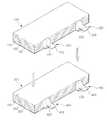
도 4를 참조하면, 상기 제1각형 리튬형 전지롤 구조체(100)는 복수개의 양극 전극판(110)과, 복수개의 음극 전극판(120)이 순차적으로 적층되며, 상기 양극 전극판(110)과 상기 음극 전극판(120)의 사이에 위치하는 복수개의 분리막(130)으로 이루어진다.Referring to FIG. 4, in the first prismatic lithium
상기 양극 전극판(110) 각각의 일단에는 제1탭(112)이 형성되고, 상기 음극 전극판(120) 각각의 일단에는 제2탭(122)이 형성되며, 상기 복수개의 제1탭(112)과 상기 복수개의 제2탭(122)이 후술되는 리벳(610)과 압착수단(620)를 이용해 압착 및 포밍하여 제1탭 압착부(140)와 제2탭 압착부(150)를 형성하며, 상기 제1탭 압착부(140)와 상기 제2탭 압착부(150)는 수평선상으로 이격되게 형성되는 것이 바람직하다.A
복수개의 상기 제1탭(112)와 상기 제2탭(122)은 용접, 솔러링, 기계적 체결부재 등 다양한 방식으로 상호 연결될 수 있으며, 바람직하게는 복수개의 상기 제1탭(112)와 상기 제2탭(122)이 삽입될 수 있는 중공구조의 리벳(610)에 의해 상호 연결될 수 있다.The plurality of
도 10을 참조하면, 상기 리벳(610)은 중공 구조로 이루어진 상단면(612)과 중공의 원형 구조로 이루어진 하단면(614)을 포함한다. 상기 하단면(614)의 장축(R1)은 상기 상단면(612)의 장축(r1)과 동일하거나 약간 큰 정도로 형성된다. 상기 상단면(612)의 단축(r2)은 상기 하단면(614)의 단축(R2)보다 휠씬 작으므로, 전체적인 형상에서 상기 리벳(610)은 단축 기준으로 하향 테이퍼되어 있는 구조로 이루어져 있다.Referring to FIG. 10, the
상기 압착수단(620)은 상기 리벳(610)의 외부에서 상기 제1탭(112)와 상기 제2탭(122)의 상부와 하부에서 압착하여 적층되어 분리된 상기 제1탭(112)와 상기 제2탭(122)를 압착하여 일체로 연결하는 역할을 한다. 상기 압착수단(620)으로는 프레스 등과 같은 압착기계가 사용되는 것이 바람직하다.The pressing means 620 is pressed and stacked on the upper and lower portions of the
상기 리벳(610)을 사용함으로 인하여 전기적 접속을 위한 용접 시의 문제점을 해결할 수 있다. 즉, 용접 등을 행할 때 용접 부위가 전극 활물질에 근접함으로 인해, 전극 활물질의 열화, 내부단락의 위험성을 감소시킬 수 있다.By using the
상기 분리막(130)은 상기 제1탭(112)과 상기 제2탭(122)을 제외한 상기 양극 전극판(110) 및 상기 음극 전극판(120)의 형상과 동일한 형상을 가지며, 절연성질을 가지는 절연재질로 형성하는 것이 바람직하다.The
상기 복수개의 양극 전극판(110)과 음극 전극판(120)의 사이에 복수개의 분리막(130)을 배치하는 목적은 상기 양극 전극판(110)과 상기 음극 전극판(120)이 서로 접지하여 전기가 빠져나가는 것을 방지하기 위함이다.The purpose of disposing the plurality of
도 7을 참조하면, 상기 제1각형 리튬형 전지롤 구조체(100)의 일단 양측에 형성된 제1탭 압착부(140)와 제2탭 압착부(150)에는 제1단자 케이스(200)가 끼워진다. 상기 제1단자 케이스(200)는 삽입부(210)와 돌출부(220)로 이루어진다.Referring to FIG. 7, a first
상기 삽입부(210)로는 상기 제1각형 리튬형 전지롤 구조체(100)의 일단 양측에 형성된 제1탭 압착부(140)와 제2탭 압착부(150)가 삽입되며, 상기 삽입부(210)의 중앙부에서 일측으로 돌출되는 돌출부(220)에는 후술되는 터미털(500)이 체결된다. 상기 돌출부(220)에는 단자체결홀(222)이 형성되며, 상기 단자체결홀(222)로는 체결수단(B)이 삽입된다.The first
도 6을 참조하면, 상기 제2각형 리튬형 전지롤 구조체(300)는 복수개의 양극 전극판(310)과, 복수개의 음극 전극판(320)이 순차적으로 적층되며, 상기 양극 전극판(310)과 상기 음극 전극판(320)의 사이에 위치하는 복수개의 분리막(330)으로 이루어진다.Referring to FIG. 6, in the second prismatic lithium
상기 양극 전극판(310) 각각의 일단에는 제3탭(312)이 형성되고, 상기 음극 전극판(320) 각각의 일단에는 제4탭(322)이 형성되며, 상기 복수개의 제3탭(312)과 상기 복수개의 제4탭(322)이 후술되는 리벳(610)과 압착수단(620)를 이용해 압착 및 포밍하여 제3탭 압착부(340)와 제4탭 압착부(350)를 형성하며, 상기 제3탭 압착부(340)와 상기 제4탭 압착부(350)는 수평선상으로 이격되게 형성되는 것이 바람직하다.A
상기 제2각형 리튬형 전지롤 구조체(300)의 일단 양측에 형성된 상기 제3탭 압착부(340)와 상기 제4탭 압착부(350)에는 상기 제1각형 리튬형 전지롤 구조체(100)와 마찬가지로 제2단자 케이스(400)가 끼워진다.The first tabular lithium
상기 제2단자 케이스(400)는 상기 제1단자 케이스(200)와 동일한 바, 그에 대한 상세한 설명은 상기 제1단자 케이스(200)에서 설명한 바, 생략하기로 한다.The second
도 8을 참조하면, 본 발명에 따른 각형 리튬형 전지롤 구조체는 상기 제1단자 케이스(200)와 상기 제2단자 케이스(400)가 끼워진 상기 제1각형 리튬형 전지롤 구조체(100)와 상기 제2각형 리튬형 전지롤 구조체(300)를 적층시킨다.Referring to FIG. 8, the prismatic lithium battery roll structure according to the present invention includes the first prismatic lithium
상기 제1각형 리튬형 전지롤 구조체(100)와 상기 제2각형 리튬형 전지롤 구조체(300)를 적층시키는 목적으로는 상기 제1각형 리튬형 전지롤 구조체(100)와 상기 제2각형 리튬형 전지롤 구조체(300)를 병렬로 연결하여 대용량의 전기를 생성하기 위함이다.In order to stack the first prismatic lithium
적층된 상기 제1각형 리튬형 전지롤 구조체(100)와 상기 제2각형 리튬형 전지롤 구조체(300)의 일단에 끼워진 상기 제1단자 케이스(200)와 상기 제2단자 케이스(400)에는 터미널(500)이 장착된다.Terminals are provided on the first
상기 터미널(500)은 사각형상의 몸체를 가지며, 상기 몸체에는 체결수단(B)이 관통하는 관통홀(510)이 형성되고, 상기 몸체의 일단에는 접지부(520)가 형성된다.The terminal 500 has a rectangular body, a through
상기 체결수단(B)는 상기 제1단자 케이스(200)의 돌출부(220)에 형성된 단자체결홀(222)를 통해 삽입되어 상기 터미널(500)의 관통홀(510)를 관통하여 상기 제2단자 케이스(400)의 돌출부(420)에 형성된 단자체결홀(422)로 삽입되어 상기 제1단자 케이스(200)와 상기 터미널(500) 및 상기 제2단자 케이스(400)를 연결한다.The fastening means (B) is inserted through the
따라서, 상기 제1각형 리튬형 전지롤 구조체(100)와 상기 제2각형 리튬형 전지롤 구조체(200)를 제1단자 케이스(200)와 제2단자 케이스(400) 및 터미널(5000를 통해 적층시킨 후 병렬로 연결함으로 인하여 대용량의 전기를 생성할 수 있다.
Therefore, the first prismatic lithium
본 발명은 도면에 도시된 실시 예를 참고로 설명되었으나 이는 예시적인 것에 불과하며, 본 기술 분야의 통상의 지식을 가진 자라면 이로부터 다양한 변형 및 균등한 다른 실시 예가 가능하다는 점을 이해할 것이다. 따라서 본 발명의 진정한 기술적 보호 범위는 첨부된 특허청구범위의 기술적 사상에 의하여 정해져야 할 것이다.While the present invention has been described with reference to exemplary embodiments, it is to be understood that the invention is not limited to the disclosed exemplary embodiments, but, on the contrary, is intended to cover various modifications and equivalent arrangements included within the spirit and scope of the appended claims. Therefore, the true technical protection scope of the present invention will be defined by the technical spirit of the appended claims.
100 : 제1각형 리튬형 전지롤 구조체110 : 양극 전극판
112 : 제1탭120 : 음극 전극판
122 : 제2탭130 : 분리막
140 : 제1탭 압착부150 : 제2탭 압착부
200 : 제1단자 케이스300 : 제2각형 리튬형 전지롤 구조체
310 : 양극 전극판312 : 제3탭
320 : 음극 전극판322 : 제4탭
330 : 분리막340 : 제3탭 압착부
350 : 제4탭 압착부400 : 제2단자 케이스
500 : 터미널610 : 리벳
620 : 압착수단100: first square lithium battery roll structure 110: positive electrode plate
112: first tab 120: cathode electrode plate
122: second tab 130: separator
140: first tap crimping part 150: second tap crimping part
200: first terminal case 300: second square lithium battery roll structure
310: positive electrode plate 312: third tab
320: cathode electrode plate 322: fourth tab
330: separation membrane 340: third tab pressing portion
350: fourth tap crimping portion 400: second terminal case
500: terminal 610: rivet
620: crimping means
Claims (5)
Translated fromKorean상기 제1각형 리튬형 전지롤 구조체의 일단 양측에 형성된 제1탭 압착부 및 제2탭 압착부에 끼워지는 제1단자 케이스;
일단에 제3탭이 형성된 복수개의 양극 전극판과, 일단에 제4탭이 형성된 복수개의 음극 전극판이 순차적으로 적층되며, 상기 양극 전극판과 상기 음극 전극판 사이에는 복수개의 분리막이 위치되며, 복수개의 상기 제3탭과 상기 제4탭을 포밍하여 제작되며, 상기 제1각형 리튬형 전지롤 구조체의 상부에 위치하는 제2각형 리튬형 전지롤 구조체;
상기 제2각형 리튬형 전지롤 구조체의 일단 양측에 형성된 제3탭 압착부 및 제4탭 압착부에 끼워지는 제2단자 케이스; 및
이격된 상기 제1단자 케이스와 상기 제2단자 케이스를 연결하는 터미널을 포함하며,
상기 제1단자 케이스와 상기 제2단자 케이스는 상기 제1탭 압착부 내지 제4탭 압착부가 삽입되는 삽입부와, 상기 삽입부의 중앙부에서 일측으로 돌출되는 돌출부로 이루어지고, 상기 돌출부에는 체결수단이 삽입되는 단자체결홀이 형성되는 각형 리튬형 전지롤 구조체.
A plurality of cathode electrode plates having a first tab formed at one end and a plurality of cathode electrode plates having a second tab formed at one end thereof are sequentially stacked, and a plurality of separators are positioned between the anode electrode plate and the cathode electrode plate. A first prismatic lithium battery roll structure formed by forming the first tabs and the second tabs;
A first terminal case fitted to a first tab pressing part and a second tab pressing part formed at both ends of one end of the first prismatic lithium battery roll structure;
A plurality of cathode electrode plates having a third tab formed at one end and a plurality of cathode electrode plates having a fourth tab formed at one end thereof are sequentially stacked, and a plurality of separators are positioned between the anode electrode plate and the cathode electrode plate. A second prismatic lithium battery roll structure formed by forming three third tabs and the fourth tabs and positioned on an upper portion of the first prismatic lithium battery roll structure;
A second terminal case fitted to a third tab pressing part and a fourth tab pressing part formed at both ends of one end of the second prismatic lithium battery roll structure; And
And a terminal connecting the spaced apart first terminal case to the second terminal case.
The first terminal case and the second terminal case comprises an insertion portion into which the first tab pressing portion to the fourth tab pressing portion are inserted, and a protrusion protruding to one side from the center portion of the insertion portion, and the fastening means is provided on the protrusion portion. A square lithium battery roll structure in which a terminal fastening hole to be inserted is formed.
상기 터미널은 사각형상의 형상의 몸체를 가지고, 상기 몸체에는 상기 체결수단이 관통하는 관통홀이 형성되며, 상기 몸체의 일단에는 접지부가 형성되는 것을 특징으로 하는 각형 리튬형 전지롤 구조체.
The method according to claim 1,
The terminal has a rectangular-shaped body, the body is formed with a through hole through which the fastening means penetrates, one end of the body is a rectangular lithium battery roll structure, characterized in that the ground portion is formed.
상기 제1각형 리튬형 전지롤 구조체는 상기 양극 전극판과 상기 음극 전극판을 적층 시에 상기 양극 전극판의 일단에 형성된 제1탭과 상기 음극 전극판의 일단에 형성된 제2탭이 수평선상으로 이격되게 형성되고,
상기 제2각형 리튬형 전지롤 구조체는 상기 양극 전극판과 상기 음극 전극판을 적층 시에 상기 양극 전극판의 일단에 형성된 제3탭과 상기 음극 전극판의 일단에 형성된 제4탭이 수평선상으로 이격되게 형성되는 것을 특징으로 하는 각형 리튬형 전지롤 구조체.
The method according to claim 1,
The first prismatic lithium battery roll structure has a first tab formed at one end of the positive electrode plate and a second tab formed at one end of the negative electrode plate when the positive electrode plate and the negative electrode plate are stacked. Formed spaced apart,
The second polygonal lithium battery roll structure has a third tab formed at one end of the positive electrode plate and a fourth tab formed at one end of the negative electrode plate when the positive electrode plate and the negative electrode plate are stacked. Square lithium battery roll structure, characterized in that formed spaced apart.
상기 제1각형 리튬형 전지롤 구조체의 제1탭 및 제2탭의 포밍과, 상기 제2각형 리튬형 전지롤 구조체의 제3탭 및 제4탭의 포밍은 리벳과 압착수단을 이용하여 상기 제1탭 내지 제4탭의 상부와 하부에서 균등하게 압착하는 것을 특징으로 하는 각형 리튬형 전지롤 구조체.
The method according to claim 1,
The forming of the first and second tabs of the first prismatic lithium battery roll structure and the forming of the third and fourth tabs of the second prismatic lithium battery roll structure using rivets and pressing means The square lithium battery roll structure, characterized in that the compression evenly on the upper and lower portions of the first tab to the fourth tab.
Priority Applications (1)
| Application Number | Priority Date | Filing Date | Title |
|---|---|---|---|
| KR1020120007369AKR101333913B1 (en) | 2012-01-25 | 2012-01-25 | Square Lithium Battery Roll Structure |
Applications Claiming Priority (1)
| Application Number | Priority Date | Filing Date | Title |
|---|---|---|---|
| KR1020120007369AKR101333913B1 (en) | 2012-01-25 | 2012-01-25 | Square Lithium Battery Roll Structure |
Publications (2)
| Publication Number | Publication Date |
|---|---|
| KR20130086484A KR20130086484A (en) | 2013-08-02 |
| KR101333913B1true KR101333913B1 (en) | 2013-11-27 |
Family
ID=49213719
Family Applications (1)
| Application Number | Title | Priority Date | Filing Date |
|---|---|---|---|
| KR1020120007369AExpired - Fee RelatedKR101333913B1 (en) | 2012-01-25 | 2012-01-25 | Square Lithium Battery Roll Structure |
Country Status (1)
| Country | Link |
|---|---|
| KR (1) | KR101333913B1 (en) |
Families Citing this family (1)
| Publication number | Priority date | Publication date | Assignee | Title |
|---|---|---|---|---|
| US10476049B2 (en)* | 2017-07-17 | 2019-11-12 | Robert Bosch Battery Systems Llc | Mechanically fastened through-wall current collector |
Citations (4)
| Publication number | Priority date | Publication date | Assignee | Title |
|---|---|---|---|---|
| KR20080009350A (en)* | 2006-07-24 | 2008-01-29 | 주식회사 엘지화학 | Secondary battery with improved capacity and safety |
| JP2009087612A (en)* | 2007-09-28 | 2009-04-23 | Sanyo Electric Co Ltd | Layered battery |
| KR20100131786A (en)* | 2009-06-08 | 2010-12-16 | 성우오토모티브 주식회사 | Battery using spot welding and manufacturing method thereof |
| KR20110061281A (en)* | 2009-12-01 | 2011-06-09 | 삼성에스디아이 주식회사 | Electrode assembly and secondary battery having same |
- 2012
- 2012-01-25KRKR1020120007369Apatent/KR101333913B1/ennot_activeExpired - Fee Related
Patent Citations (4)
| Publication number | Priority date | Publication date | Assignee | Title |
|---|---|---|---|---|
| KR20080009350A (en)* | 2006-07-24 | 2008-01-29 | 주식회사 엘지화학 | Secondary battery with improved capacity and safety |
| JP2009087612A (en)* | 2007-09-28 | 2009-04-23 | Sanyo Electric Co Ltd | Layered battery |
| KR20100131786A (en)* | 2009-06-08 | 2010-12-16 | 성우오토모티브 주식회사 | Battery using spot welding and manufacturing method thereof |
| KR20110061281A (en)* | 2009-12-01 | 2011-06-09 | 삼성에스디아이 주식회사 | Electrode assembly and secondary battery having same |
Also Published As
| Publication number | Publication date |
|---|---|
| KR20130086484A (en) | 2013-08-02 |
Similar Documents
| Publication | Publication Date | Title |
|---|---|---|
| US12068506B2 (en) | Flexible battery | |
| KR100866767B1 (en) | Secondary battery safety member | |
| KR101265199B1 (en) | Rechargeable battery | |
| EP2779269B1 (en) | Battery cell having a novel structure | |
| KR100599752B1 (en) | Secondary Battery and Electrode Assembly Used in the Same | |
| JP2024096240A (en) | Energy Storage Module | |
| KR101565115B1 (en) | Battery Pack and method for manufacturing the same | |
| KR101125592B1 (en) | High Capacity Battery Cell of High Life Characteristics and Safety | |
| KR102051109B1 (en) | Battery Module | |
| EP3486967B1 (en) | Battery cell comprising electrode lead facing outer surface of electrode assembly | |
| KR100786875B1 (en) | Battery module | |
| KR100893225B1 (en) | Secondary battery with improved capacity and safety | |
| EP2302717A1 (en) | Electrode assembly for a rechargeable battery | |
| KR20210021841A (en) | Rechargeable battery | |
| KR20160023038A (en) | A Battery cell Having Improved Cooling Performance | |
| KR20150035205A (en) | Secondary battery | |
| KR20180085446A (en) | Battery Pack Comprising Electrode Terminal Connecting Plate | |
| KR101370144B1 (en) | Square lithium type cell | |
| KR102265846B1 (en) | Battery Pack Comprising Electrode Terminal Connecting Plate | |
| KR101749729B1 (en) | Secondary battery | |
| KR101906923B1 (en) | Battery Module and Laser welding method for Battery Module | |
| KR20170110821A (en) | Battery Cell Comprising Cylindrical Can Having Screw-typed Fastening Portion | |
| KR20060112034A (en) | Secondary battery | |
| KR100877811B1 (en) | Secondary battery safety member with steps formed on both sides | |
| KR101333913B1 (en) | Square Lithium Battery Roll Structure |
Legal Events
| Date | Code | Title | Description |
|---|---|---|---|
| A201 | Request for examination | ||
| PA0109 | Patent application | St.27 status event code:A-0-1-A10-A12-nap-PA0109 | |
| PA0201 | Request for examination | St.27 status event code:A-1-2-D10-D11-exm-PA0201 | |
| P11-X000 | Amendment of application requested | St.27 status event code:A-2-2-P10-P11-nap-X000 | |
| P13-X000 | Application amended | St.27 status event code:A-2-2-P10-P13-nap-X000 | |
| R15-X000 | Change to inventor requested | St.27 status event code:A-3-3-R10-R15-oth-X000 | |
| R16-X000 | Change to inventor recorded | St.27 status event code:A-3-3-R10-R16-oth-X000 | |
| D13-X000 | Search requested | St.27 status event code:A-1-2-D10-D13-srh-X000 | |
| D14-X000 | Search report completed | St.27 status event code:A-1-2-D10-D14-srh-X000 | |
| E902 | Notification of reason for refusal | ||
| PE0902 | Notice of grounds for rejection | St.27 status event code:A-1-2-D10-D21-exm-PE0902 | |
| E13-X000 | Pre-grant limitation requested | St.27 status event code:A-2-3-E10-E13-lim-X000 | |
| P11-X000 | Amendment of application requested | St.27 status event code:A-2-2-P10-P11-nap-X000 | |
| P13-X000 | Application amended | St.27 status event code:A-2-2-P10-P13-nap-X000 | |
| PG1501 | Laying open of application | St.27 status event code:A-1-1-Q10-Q12-nap-PG1501 | |
| E701 | Decision to grant or registration of patent right | ||
| PE0701 | Decision of registration | St.27 status event code:A-1-2-D10-D22-exm-PE0701 | |
| GRNT | Written decision to grant | ||
| PR0701 | Registration of establishment | St.27 status event code:A-2-4-F10-F11-exm-PR0701 | |
| PR1002 | Payment of registration fee | Fee payment year number:1 St.27 status event code:A-2-2-U10-U11-oth-PR1002 | |
| PG1601 | Publication of registration | St.27 status event code:A-4-4-Q10-Q13-nap-PG1601 | |
| R18-X000 | Changes to party contact information recorded | St.27 status event code:A-5-5-R10-R18-oth-X000 | |
| PN2301 | Change of applicant | St.27 status event code:A-5-5-R10-R11-asn-PN2301 St.27 status event code:A-5-5-R10-R13-asn-PN2301 | |
| FPAY | Annual fee payment | Payment date:20161114 Year of fee payment:4 | |
| PR1001 | Payment of annual fee | Fee payment year number:4 St.27 status event code:A-4-4-U10-U11-oth-PR1001 | |
| P22-X000 | Classification modified | St.27 status event code:A-4-4-P10-P22-nap-X000 | |
| PN2301 | Change of applicant | St.27 status event code:A-5-5-R10-R11-asn-PN2301 St.27 status event code:A-5-5-R10-R13-asn-PN2301 | |
| FPAY | Annual fee payment | Payment date:20171120 Year of fee payment:5 | |
| PR1001 | Payment of annual fee | Fee payment year number:5 St.27 status event code:A-4-4-U10-U11-oth-PR1001 | |
| FPAY | Annual fee payment | Payment date:20181119 Year of fee payment:6 | |
| PR1001 | Payment of annual fee | Fee payment year number:6 St.27 status event code:A-4-4-U10-U11-oth-PR1001 | |
| FPAY | Annual fee payment | Payment date:20191014 Year of fee payment:7 | |
| PR1001 | Payment of annual fee | Fee payment year number:7 St.27 status event code:A-4-4-U10-U11-oth-PR1001 | |
| R18-X000 | Changes to party contact information recorded | St.27 status event code:A-5-5-R10-R18-oth-X000 | |
| PR1001 | Payment of annual fee | Fee payment year number:8 St.27 status event code:A-4-4-U10-U11-oth-PR1001 | |
| R18-X000 | Changes to party contact information recorded | St.27 status event code:A-5-5-R10-R18-oth-X000 | |
| P22-X000 | Classification modified | St.27 status event code:A-4-4-P10-P22-nap-X000 | |
| PR1001 | Payment of annual fee | Fee payment year number:9 St.27 status event code:A-4-4-U10-U11-oth-PR1001 | |
| R18-X000 | Changes to party contact information recorded | St.27 status event code:A-5-5-R10-R18-oth-X000 | |
| P22-X000 | Classification modified | St.27 status event code:A-4-4-P10-P22-nap-X000 | |
| PR1001 | Payment of annual fee | Fee payment year number:10 St.27 status event code:A-4-4-U10-U11-oth-PR1001 | |
| P14-X000 | Amendment of ip right document requested | St.27 status event code:A-5-5-P10-P14-nap-X000 | |
| PN2301 | Change of applicant | St.27 status event code:A-5-5-R10-R11-asn-PN2301 | |
| P16-X000 | Ip right document amended | St.27 status event code:A-5-5-P10-P16-nap-X000 | |
| PN2301 | Change of applicant | St.27 status event code:A-5-5-R10-R14-asn-PN2301 | |
| PC1903 | Unpaid annual fee | Not in force date:20231122 Payment event data comment text:Termination Category : DEFAULT_OF_REGISTRATION_FEE St.27 status event code:A-4-4-U10-U13-oth-PC1903 | |
| PC1903 | Unpaid annual fee | Ip right cessation event data comment text:Termination Category : DEFAULT_OF_REGISTRATION_FEE Not in force date:20231122 St.27 status event code:N-4-6-H10-H13-oth-PC1903 | |
| R18-X000 | Changes to party contact information recorded | St.27 status event code:A-5-5-R10-R18-oth-X000 |