KR101333023B1 - Lamp module and lighting device comprising such a lamp module - Google Patents
Lamp module and lighting device comprising such a lamp moduleDownload PDFInfo
- Publication number
- KR101333023B1 KR101333023B1KR1020087020001AKR20087020001AKR101333023B1KR 101333023 B1KR101333023 B1KR 101333023B1KR 1020087020001 AKR1020087020001 AKR 1020087020001AKR 20087020001 AKR20087020001 AKR 20087020001AKR 101333023 B1KR101333023 B1KR 101333023B1
- Authority
- KR
- South Korea
- Prior art keywords
- lamp module
- cell
- lighting device
- light
- led chip
- Prior art date
- Legal status (The legal status is an assumption and is not a legal conclusion. Google has not performed a legal analysis and makes no representation as to the accuracy of the status listed.)
- Expired - Fee Related
Links
Images


Classifications
- F—MECHANICAL ENGINEERING; LIGHTING; HEATING; WEAPONS; BLASTING
- F21—LIGHTING
- F21V—FUNCTIONAL FEATURES OR DETAILS OF LIGHTING DEVICES OR SYSTEMS THEREOF; STRUCTURAL COMBINATIONS OF LIGHTING DEVICES WITH OTHER ARTICLES, NOT OTHERWISE PROVIDED FOR
- F21V14/00—Controlling the distribution of the light emitted by adjustment of elements
- F21V14/003—Controlling the distribution of the light emitted by adjustment of elements by interposition of elements with electrically controlled variable light transmissivity, e.g. liquid crystal elements or electrochromic devices
- F—MECHANICAL ENGINEERING; LIGHTING; HEATING; WEAPONS; BLASTING
- F21—LIGHTING
- F21V—FUNCTIONAL FEATURES OR DETAILS OF LIGHTING DEVICES OR SYSTEMS THEREOF; STRUCTURAL COMBINATIONS OF LIGHTING DEVICES WITH OTHER ARTICLES, NOT OTHERWISE PROVIDED FOR
- F21V5/00—Refractors for light sources
- F—MECHANICAL ENGINEERING; LIGHTING; HEATING; WEAPONS; BLASTING
- F21—LIGHTING
- F21K—NON-ELECTRIC LIGHT SOURCES USING LUMINESCENCE; LIGHT SOURCES USING ELECTROCHEMILUMINESCENCE; LIGHT SOURCES USING CHARGES OF COMBUSTIBLE MATERIAL; LIGHT SOURCES USING SEMICONDUCTOR DEVICES AS LIGHT-GENERATING ELEMENTS; LIGHT SOURCES NOT OTHERWISE PROVIDED FOR
- F21K9/00—Light sources using semiconductor devices as light-generating elements, e.g. using light-emitting diodes [LED] or lasers
- F21K9/20—Light sources comprising attachment means
- F—MECHANICAL ENGINEERING; LIGHTING; HEATING; WEAPONS; BLASTING
- F21—LIGHTING
- F21Y—INDEXING SCHEME ASSOCIATED WITH SUBCLASSES F21K, F21L, F21S and F21V, RELATING TO THE FORM OR THE KIND OF THE LIGHT SOURCES OR OF THE COLOUR OF THE LIGHT EMITTED
- F21Y2115/00—Light-generating elements of semiconductor light sources
- F21Y2115/10—Light-emitting diodes [LED]
Landscapes
- Engineering & Computer Science (AREA)
- General Engineering & Computer Science (AREA)
- Chemical & Material Sciences (AREA)
- Crystallography & Structural Chemistry (AREA)
- Physics & Mathematics (AREA)
- Microelectronics & Electronic Packaging (AREA)
- Optics & Photonics (AREA)
- Non-Portable Lighting Devices Or Systems Thereof (AREA)
- Circuit Arrangement For Electric Light Sources In General (AREA)
- Led Devices (AREA)
Abstract
Translated fromKorean
Description
Translated fromKorean본 발명은 LED(light emitting diode) 램프 모듈 및 이러한 램프 모듈을 포함하는 조명 디바이스에 관한 것이다.The present invention relates to a light emitting diode (LED) lamp module and a lighting device comprising such a lamp module.
전자 장치가 통합되어 있는 LED 램프 모듈이 최근 시장에서 사용가능하게 되어 오고 있다. 이러한 LED 램프 모듈은, 예를 들면, 자전거 램프(bicycle lamp), 토치/플래시 램프(torch/flash lamp), 전조등(head lamp) 등 각종 조명 디바이스에서 사용될 수 있다.LED lamp modules incorporating electronic devices have recently become available on the market. Such LED lamp modules can be used in various lighting devices such as, for example, bicycle lamps, torch / flash lamps, head lamps.
이러한 조명 디바이스에서 뿐만 아니라 통상적인 광원 또는 램프 모듈을 갖는 다른 조명 디바이스에서도, 조명 디바이스의 광원으로부터 시작되는(originate) 빛의 방향 및 쉐이프(shape)를 조정하는 것이 바람직하다. 이것은, 예를 들면, 광원에 대해 반사기의 위치를 이동시킴으로써, 또는 문헌 US 6357893호에 개시되어 있는 바와 같이 유연한 기판 상에 다수의 광원을 배열함으로써와 같이, 기계적으로 달성될 수 있다. US 6357893호에서는, 볼록한 방식의 요면(concave of convex manner)에 기판을 구부려서, 콜리메이션과 빔 크기를 바꿀 수 있는 기계적인 수단이 제공된다. 빔 크기의 조정은, 이것이 원하는 순간에 빔을 넓히는 것을 가능하 게 하기 때문에 이롭다.In such lighting devices as well as other lighting devices having conventional light sources or lamp modules, it is desirable to adjust the direction and shape of the light originating from the light source of the lighting device. This can be achieved mechanically, for example by moving the position of the reflector relative to the light source, or by arranging a plurality of light sources on a flexible substrate as disclosed in document US 6357893. In US 6357893, mechanical means are provided for bending a substrate in a concave of convex manner to change collimation and beam size. Adjustment of the beam size is advantageous because it makes it possible to widen the beam at the desired moment.
그러나, 기계적인 해결책은 다소 느리고 신뢰할 수 없어(US 6357893호의 기판은 빠질 수 있음(the substrate in US 6357893 can get stuck)), 사용자들은 빔의 쉐이프를 바꾸기 위해 조명 디바이스의 엘리먼트(예를 들면, 반사기 전체)를 이동시키거나 또는 이를 돌리는(turn) 것과 같은 상당한 수작업을 실행해야 한다.
US-A-5424927에서는, 예컨대, 공칭(nominal) 3V 램프 또는 LED와 같은 전형적인 광원의 (전기 광학적으로 제어되는 구역이) 앞에 배치되어 있는 플래시라이트를 개시한다.However, the mechanical solution is rather slow and unreliable (the substrate in US 6357893 can get stuck), so users can change the shape of the beam to change the shape of the beam (eg reflector). Considerable manual work must be performed, such as moving the whole) or turning it.
US-A-5424927 discloses a flashlight which is placed in front of (e.g., an electro-optically controlled zone) of a typical light source, for example a nominal 3V lamp or LED.
본 발명의 목적은 이러한 문제를 극복하는 것이며, 단독으로 또는 조명 디바이스에 장착될 때, 빔 쉐이핑(shaping) 및 빔 방향 조정 기능을 가능하게 하는 램프 모듈을 제공하는 것이다.It is an object of the present invention to overcome this problem and to provide a lamp module that enables beam shaping and beam direction adjustment functions, either alone or when mounted to a lighting device.
이하의 상세한 설명으로부터 명백하게 될 이들 및 다른 목적들은 첨부된 청구항에 따라, 램프 모듈 및 이러한 램프 모듈을 포함하는 조명 디바이스에 의해 달성된다.These and other objects, which will become apparent from the following detailed description, are achieved by a lamp module and a lighting device comprising such lamp module, in accordance with the appended claims.
본 발명의 한 양태에 따르면, 발광용의 적어도 하나의 LED 칩, 이 칩(들)으로부터 방출되는 빛을 추출하고 쉐이핑하기 위한 수단, 및 이 램프 모듈이 조명 디바이스에 고정되고 연결되는 것을 가능하게 하는 베이스(base)를 포함하며, 이 램프 모듈은, 이 칩(들)으로부터 방출되는 빛을 수광하도록 적응되는 적어도 하나의 전기적으로 전환가능한 셀을 특징으로 하며, 이 셀은 제1 상태에서는 빛의 방향을 거의 바꾸지 않으면서 입사하는 빛을 투과시키고, 제2 상태에서는 빛이 셀(들)을 통과할 때 빛의 방향을 바꾼다.According to one aspect of the invention, there is provided at least one LED chip for emitting light, means for extracting and shaping light emitted from the chip (s), and enabling the lamp module to be fixed and connected to the lighting device. A base comprising a base, wherein the lamp module features at least one electrically switchable cell adapted to receive light emitted from the chip (s), the cell in the first state of light direction It transmits the incident light with little change, and in the second state it changes the direction of light as it passes through the cell (s).
따라서, LED 칩, 추출 광학 기기, 베이스 및 셀은 조명 디바이스에 고정되도록 의도되는, 하나의 통합된 유닛을 형성한다. 셀을 LED 칩(들) 앞에 배치함으로써, 단지 셀의 상태를 전기적으로 제어함으로써 LED 칩(들)으로부터의 빛의 분산을 바꾸는 것이 가능하게 되며, 이어서 전기적으로 제어되는 조정가능한 빔 쉐이핑을 제공하는 것도 가능하게 된다. 셀이 램프 모듈에 통합되면, 셀은 일반적으로 LED 칩에 근접하여 위치된다.Thus, the LED chip, extraction optics, base and cell form one integrated unit, which is intended to be fixed to the lighting device. By placing the cell in front of the LED chip (s), it is possible to change the distribution of light from the LED chip (s) by merely controlling the state of the cell, and subsequently providing electrically controlled adjustable beam shaping. It becomes possible. Once the cell is integrated into the lamp module, the cell is generally located in close proximity to the LED chip.
LED 칩(들)으로부터 방출되는 빛을 추출하고 쉐이핑하기 위한 수단은, LED 칩(들) 위에 및/또는 그 주위에 배치될 수 있고, 이 수단은 일반적으로 LED 칩(들)으로부터의 빛이 앞으로 향하게 하는 기능을 한다. 예를 들면, 이 수단은 칩(들) 위에 배치되어 콜리메이트된 측면 방출(collimated side emission)(즉, 측면 방출 LED)을 유도하도록 적응되는 광학 기기를 포함할 수 있으며, 이 경우, 이 수단은 측면 방출 LED로부터의 빛이 셀로 향하도록 하는 반사기를 더 포함할 수 있다. 대안으로는, LED 칩(들)으로부터 방출되는 빛을 추출하고 쉐이핑하기 위한 수단은, 예를 들면, 등방성 방출 LED(isotropic emission LED)를 가능하게 하는 돔과 같은, LED 칩(들)으로부터의 빛을 소정의 방향으로 향하게 하도록 형성된 광학 기기를 포함할 수 있다. 이러한 돔은, 등방성 방출 LED로부터의 빛을 콜리메이팅하고 이를 셀로 향하도록 하기 위해, 내부 전반사(total internal reflection, TIR) 광학 기기 또는 굴절 또는 반사 엘리먼트 또는 그 조합과 선택적으로 결합될 수 있다. Means for extracting and shaping the light emitted from the LED chip (s) can be disposed on and / or around the LED chip (s), which means that generally the light from the LED chip (s) is forwarded. It functions to direct. For example, the means may include optics disposed on the chip (s) and adapted to induce collimated side emission (ie, side emitting LEDs), in which case the means It may further include a reflector for directing light from the side emitting LEDs to the cell. Alternatively, the means for extracting and shaping the light emitted from the LED chip (s) may be, for example, light from the LED chip (s), such as a dome enabling an isotropic emission LED. It may include an optical device formed to direct in a predetermined direction. Such a dome can optionally be combined with total internal reflection (TIR) optics or refractive or reflective elements or combinations thereof to collimate and direct light from the isotropic emitting LEDs to the cell.
한 실시예에서, 적어도 하나의 셀이 칩(들)으로부터 방출되는 빛을 추출하고 쉐이핑하기 위한 수단 내에 통합될 수 있다. 예를 들면, 셀은 상술된 돔 광학 기기를 둘러싸는 TIR 광학 기기 내에 통합될 수 있다. 칩(들)으로부터 방출되는 빛을 추출하고 쉐이핑하기 위한 수단 내에 셀을 통합시키는 것은, 입사하는 빛의 방향을 큰 각도로 바꾸는 셀이 사용되는 경우 특히 이롭다. 이러한 셀이 입사하는 빛의 방향을 큰 각도로 바꾸는 경우, 즉, 빛이 앞이 아니라 옆으로 향할 때, 그 결과는 빔 쉐이핑이 아니라 디밍 효과일 수 있는데, 즉, 너무 넓은 빔이 달성된다. 그러나, 셀을 추출/쉐이핑 수단 내로 통합함으로써, 이후 이 수단은 LED 칩(들)으로부터 방출되는 빛이 그러한 바와 같이, 빛이 옆으로 향하게 하는 것을 도울 수 있어, 디밍을 피하고 덜 넓은 빔이 달성된다. 여기서, 램프 모듈은 단독으로 빔 쉐이핑 기능을 가능하게 한다.In one embodiment, at least one cell may be integrated into the means for extracting and shaping the light emitted from the chip (s). For example, the cell may be integrated into the TIR optics surrounding the dome optics described above. Incorporating the cell into the means for extracting and shaping the light emitted from the chip (s) is particularly advantageous when a cell is used that changes the direction of the incident light at a large angle. When such a cell changes the direction of incident light at a large angle, that is, when the light is directed laterally rather than forward, the result may be a dimming effect rather than beam shaping, ie a too wide beam is achieved. However, by integrating the cell into the extraction / shaping means, this means can then help the light emitted from the LED chip (s) to be directed sideways, as such, avoiding dimming and a less wide beam is achieved. . Here, the lamp module alone enables the beam shaping function.
대안으로, 셀은 LED 칩(들)으로부터 방출되는 빛을 추출하고 쉐이핑하기 위한 수단 위에(측면 발광 LED 또는 등방성 방출 LED 및 선택적인 TIR 광학 기기 위에) 장착될 수 있다. 이러한 경우, 램프 모듈을 조명 디바이스의 반사기에 장착함으로써, 또는 입사하는 빛의 방향을 이러한 큰 각도로 바꾸지 않는 셀을 사용함으로써, 디밍을 피할 수 있다.Alternatively, the cell may be mounted on the means for extracting and shaping the light emitted from the LED chip (s) (on the side emitting LED or isotropic emitting LED and optional TIR optics). In this case, dimming can be avoided by mounting the lamp module to the reflector of the lighting device or by using a cell that does not change the direction of incident light at such a large angle.
입사하는 빛의 방향은, 예를 들면, 산란(scattering), 굴절(refraction), 반사(reflection) 또는 회절(diffraction) 중 하나의 방법에 의해 셀에 의해 바뀔 수 있다. 게다가, 램프 모듈은, 원하는 방식으로 LED 칩으로부터의 빛의 분산을 바꾸는 데 있어 더 큰 적응성 및 더 많은 가능성을 가능하게 하는 서로 다른 효과를 갖는 복수의 셀을 포함할 수 있다. 예를 들면, LED 칩(들)으로부터의 빛을 산란시키는 셀은 입사하는 빛을 회절시키는 또 다른 셀 위에 위치될 수 있다.The direction of incident light can be changed by the cell, for example by one of scattering, refraction, reflection, or diffraction. In addition, the lamp module may include a plurality of cells with different effects that allow greater adaptability and more possibilities in changing the distribution of light from the LED chip in a desired manner. For example, a cell that scatters light from the LED chip (s) can be placed over another cell that diffracts incident light.
램프 모듈은 LED 칩에 연결된 LED 구동기를 더 포함할 수 있다. 램프 모듈의 전력원에 따라, LED 구동기는 AC-DC 변환기 또는 DC-AC 변환기를 포함할 수 있다. 구동기는, 예를 들면, 주파수 변조, 펄스 폭 변조 또는 비트 각도 변조를 이용하여 LED 칩에 전류를 공급(supply)할 수 있다.The lamp module may further include an LED driver connected to the LED chip. Depending on the power source of the lamp module, the LED driver may comprise an AC-DC converter or a DC-AC converter. The driver may supply current to the LED chip using, for example, frequency modulation, pulse width modulation or bit angle modulation.
게다가, 램프 모듈은 배터리와 같은 외부 전력원으로부터의 직류를 셀에 공급하기 위해 교류로 변환하기 위한 DC-AC 변환기를 포함할 수 있다. 셀은 일반적으로 교류를 필요로 하므로, 램프 모듈이 일반적인 배터리에 의해 전력이 공급되는 플래시라이트와 같은 직류로 동작되는 조명 디바이스에 장착되어 있는 경우, DC-AC 변환기가 이용될 수 있다.In addition, the lamp module may include a DC-AC converter for converting direct current from an external power source such as a battery into alternating current for supplying the cell. Since cells typically require alternating current, a DC-AC converter can be used when the lamp module is mounted in a direct current operated lighting device such as a flashlight powered by a typical battery.
램프 모듈은 공통 입력 신호에 기초하여 셀의 상태와 LED 칩(들)을 개별적으로 제어하도록 구성된 프로세서를 더 포함할 수 있다. 더욱 구체적으로는, 프로세서는, (램프 모듈이 장착되는 조명 디바이스 상의 사용자 조작 스위치로부터 나오는(come) 것이 바람직한) 신호 펄스의 지속기간/시퀀스/갯수를 변환하여(translate), 그에 따라 LED 칩과 셀의 상태를 개별적으로 제어하도록 적응된다. 예를 들면, 단일의 짧은 펄스는 프로세서로 하여금 LED 칩만을 활성화시키도록 할 수 있지만, 단일의 더 긴 펄스는 프로세서에게 LED 칩과 셀 둘 다를 활성화시키도록 지시할 수 있다. 프로세서는 통합된 LED 구동기와 DC-AC 변환기와 함께, 보통의 플래시라이트와 같은 기존의 조명 디바이스에 쉽게 개장될(retrofitted) 수 있는 (조명 디바이스의 스위치 및 전력원에 대한) 두 개의 접점만이 있는 램프 모듈을 허용한다. 즉, 모든 광학 컴포넌트 및 전자 컴포넌트가 소형의 램프 모듈 내에 통합된다. 게다가, LED(온/오프) 및 셀(빔 쉐이핑) 둘 다가 단일의 스위치로 동작될 수 있다.The lamp module may further include a processor configured to individually control the state of the cell and the LED chip (s) based on the common input signal. More specifically, the processor translates the duration / sequence / number of signal pulses (preferably from the user-operated switch on the lighting device to which the lamp module is mounted), thereby converting the LED chips and cells. It is adapted to individually control the state of. For example, a single short pulse may cause the processor to activate only the LED chip, while a single longer pulse may instruct the processor to activate both the LED chip and the cell. The processor, with an integrated LED driver and DC-AC converter, has only two contacts (to the switch and power source of the lighting device) that can be easily retrofitted to existing lighting devices such as ordinary flashlights. Allow the lamp module. That is, all optical and electronic components are integrated into a compact lamp module. In addition, both the LED (on / off) and the cell (beam shaping) can be operated as a single switch.
대안으로, 램프 모듈은 가변 입력 전압을, LED 칩(들)에 공급되는 정 직류(constant direct current) 및 셀에 공급되는 가변 교류(variable alternating current)로 변환하는 수단을 포함할 수 있으며, 셀에 공급되는 교류는 입력 전압에 따라 달라진다. 이에 의해, 입력 전압을 램프 모듈에 맞춤으로써(adjust) 빔 쉐이핑이 제어될 수 있다. 이것은 또한 응용물들을 개장시키는 것을 허용한다(This also allows retrofit applications). 상술된 DC-AC 변환기는 여기서 가변 입력 전압을 셀에 공급되는 가변 교류로 변환시키는 데에 사용될 수 있다.Alternatively, the lamp module may comprise means for converting a variable input voltage into a constant direct current supplied to the LED chip (s) and a variable alternating current supplied to the cell, The alternating current supplied depends on the input voltage. Thereby, beam shaping can be controlled by adjusting the input voltage to the lamp module. This also allows retrofit applications. The DC-AC converter described above can be used here to convert a variable input voltage into a variable alternating current supplied to a cell.
본 발명의 또 다른 양태에 따르면, 상술된 설명에 따르는 램프 모듈을 포함하는 조명 디바이스가 제공된다. 조명 디바이스는 논-메인즈 접속 디바이스(non-mains connected device) 및/또는 핸드 헬드 디바이스일 수 있다. 예를 들면, 조명 디바이스는 토치 램프 또는 플래시라이트, 자전거 램프, 전조등, 라이플 램프, 다이빙 램프(diving lamp), 광부의 램프(miners lamp), 비상 상태 램프(emergency lamp), 스포트라이트(spot light) 등 일 수 있다.According to another aspect of the invention, there is provided a lighting device comprising a lamp module according to the above description. The lighting device may be a non-mains connected device and / or a hand held device. For example, the lighting device may be a torch lamp or flashlight, bicycle lamp, headlight, rifle lamp, diving lamp, miners lamp, emergency lamp, spot light and the like. Can be.
조명 디바이스는 배터리와 같은 내부 전력원으로부터의 직류를 셀에 공급되는 교류로 변환하는 DC-AC 변환기를 포함할 수 있다. 이 경우, 상술된 램프 모듈에 제공되는 DC-AC 변환기는 생략될 수 있다.The lighting device may include a DC-AC converter that converts direct current from an internal power source such as a battery into alternating current supplied to the cell. In this case, the DC-AC converter provided in the lamp module described above may be omitted.
게다가, 상술된 설명에 따른 프로세서를 포함하는 경우, 조명 디바이스는 프로세서에 입력 신호를 제공하는 단일의 스위치를 포함하는 것이 바람직하다. 대안으로는, 램프 모듈에 프로세서가 없다면, 조명 디바이스는 대신, 셀의 상태를 제어하기 위한 제1 스위치와 LED 칩을 제어하기 위한 제2 스위치를 포함할 수 있다.In addition, when including the processor according to the above description, the lighting device preferably comprises a single switch for providing an input signal to the processor. Alternatively, if the lamp module does not have a processor, the lighting device may instead include a first switch for controlling the state of the cell and a second switch for controlling the LED chip.
또한, 조명 디바이스는 빔 쉐이퍼(beam shaper)를 포함하는 것이 바람직하며, 이 경우 램프 모듈이 빔 쉐이퍼에 위치된다. 빔 쉐이퍼는, 예를 들면, 내부 전반사(TIR) 광학 기기, 또는 (반사기와 같은) 굴절 또는 반사 엘리먼트, 또는 그 둘의 조합을 포함할 수 있다. 반사기(또는 유사한 수단)는 조정가능한 빔 쉐이핑에 대해 더 양호한 제어를 제공한다.In addition, the illumination device preferably comprises a beam shaper, in which case the lamp module is located in the beam shaper. The beam shaper may include, for example, total internal reflection (TIR) optics, or refractive or reflective elements (such as reflectors), or a combination of both. Reflectors (or similar means) provide better control over adjustable beam shaping.
도 1a 및 도 1b는 셀이 각각 제1 및 제2 상태에 있는, 본 발명의 실시예에 따른 램프 모듈을 도시하는 횡단면도.1A and 1B are cross-sectional views illustrating a lamp module according to an embodiment of the present invention, with the cells in first and second states, respectively.
도 2a 내지 도 5b는 도 1a 및 도 1b의 램프 모듈의 변형.2A-5B are variations of the lamp module of FIGS. 1A-1B.
도 6a 및 도 6b는 램프 모듈의 셀이 각각 제1 및 제2 상태에 있는, 본 발명의 실시예에 따른 조명 디바이스.6A and 6B show an illumination device according to an embodiment of the invention, wherein the cells of the lamp module are in first and second states, respectively.
도 7은 본 발명에 따른 조명 디바이스와 램프 모듈의 상세도.7 shows a detailed view of a lighting device and a lamp module according to the invention.
도 8은 도 7의 조명 디바이스와 램프 모듈의 변형.8 shows a variant of the lighting device and lamp module of FIG. 7.
도 9는 도 7의 조명 디바이스와 램프 모듈의 또 다른 변형.9 is another variant of the lighting device and lamp module of FIG.
본 발명의 이들 및 다른 양태들은 이제 본 발명의 바람직한 실시예를 현재 도시하고 있는 첨부된 도면을 참조함으로써 더 상세하게 기술될 것이다.These and other aspects of the invention will now be described in more detail by reference to the accompanying drawings, which presently show preferred embodiments of the invention.
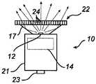
도 1a 및 도 1b는 본 발명의 실시예에 따른 램프 모듈(10)을 도시하는 횡단면도이다. 램프 모듈(10)은 베이스(21)에 장착된 LED 칩(12)과, 콜리메이트된 측 면 방출(side emission)(즉, 측면 발광 LED)을 유도하기 위해 LED 칩(12) 상에 배치되는 광학 기기(13)를 포함한다. LED 칩(12)은 LED 구동기(14)에 연결된다. LED 칩(12)과 광학 기기(13)는 광선의 흔적(ray-trace)(18, 20)에 의해 표시되는 바와 같이, LED 칩(12)으로부터 방출되는 빛을 앞으로 반사시키기 위한 반사기(16)에 의해 둘러싸인다. 베이스(21)는 조명 디바이스의 램프 소켓(미도시)에 꼭 맞도록 적응되며, 램프 모듈(10)과 조명 디바이스 간의 전기적 연결을 위한 접점(23)을 포함한다.1A and 1B are cross-sectional views illustrating
LED 칩(12)과 광학 기기(13) 앞에, 전기적으로 전환가능한 셀(22)이 제공된다. 이 셀(22)은, 도 1a의 광선의 흔적(18)으로 나타난 바와 같이, 빛의 방향을 거의 바꾸지 않으면서 LED 칩(12)으로부터 시작되어 입사하는 빛을 투과시키는 제1 상태를 지니며, 제2 상태에서는, 빛이 셀(22)을 통과할 때, 도 1b의 광선의 흔적(20)으로 나타난 바와 같이, 입사하는 빛의 방향을 바꾼다. 따라서, 동작 시, 셀(22)이 제1 상태에 있는 경우, LED 칩(12)으로부터 시작되는 빛은 셀이 바뀌지 않게 하지만, 제2 상태에서는 빛의 경로가 바뀐다. In front of the
셀(22)은, 예를 들면, 단일의 픽셀, 또는 픽셀들의 어레이를 포함하는 액정 셀이거나, 또는 (도 1a 및 도 1b에 있는) 조명 변조 엘리먼트(24)일 수 있다. 셀은 액티브 매트릭스 어드레싱, 멀티플렉스된 어드레싱, 또는 다이렉트 전기 어드레싱을 지닐 수 있으며, 입사하는 빛의 방향이나 경로를 바꾸는 것은, 산란, 굴절, 반사 또는 회절과 같은 전기적으로 제어가능한 액정 효과를 이용하여 달성될 수 있다. 셀(22)은 거의 모든 빛이 앞쪽으로 산란되도록(또는 굴절되거나 또는 반사되 거나 또는 회절되도록), 즉, LED 칩(12)을 향해 뒤쪽으로 산란되지 않도록 설계되는 것이 바람직하다. 본 발명에 적합한 각종 액정 효과/디바이스(셀)가 당업자에게 명백할 것이다. 예를 들면, 전기적으로 제어가능한 산란(PDLC, 겔 등), LC 그레이디드 굴절률 광학 기기(LC graded refractive index optics)(렌즈 어레이 등), 콜레스트릭 반사기(cholestric reflector), 표면 토폴로지 커버된 LC 광학 기기(회절 격자(grating), 마이크로 렌즈 어레이 등과 같은 표면 부조(surface relief)가 있는 구조물을 포함하는 LC 셀) 등이 있을 수 있다.
일부 셀들(예를 들면, PDLC)은, "투명 상태"에서조차도 일부 입사하는 빛의 방향, 즉, 큰 각도로 셀을 향해 들어오고 있는 빛의 방향을 바꿀 수 있다는 것을 유의한다. 따라서, 빛의 일부만이 방향이 바뀌지 않은 채 셀을 투과한다. 이러한 셀은, 물론, 빛의 대부분이 거의 직각으로 셀에 떨어지는 경우 주요 문제를 절대 만들지 않는다. 그러나, 일부 빛이 큰 각도로 셀을 향해 들어오고 있다면, 예를 들면 (등방성의 방출 LED와 같은) 광원이 셀에 매우 가까이 배치되어 있다면, 이 빛은 그 셀이 "온" 또는 "오프"인지의 여부에 따라 방향이 변할 것이다. 따라서, 셀을 턴 온/턴 오프하는 빔 쉐이핑 효과는 사라진다. 그러므로, 빛이 큰 각도로 셀을 향해 들어오고 있는 경우, 예를 들면, LED 칩이 셀에 매우 가까이 위치되어 있다면, 셀의 상태가 전환될 때 주목할 만한 빔 쉐이핑을 달성하기 위해서는, 빛의 방향을 바꾸지 않고, 입사각에 상관없이, 투명 상태에서 거의 모든 빛을 투과시키는 셀을 이용하는 것이 이롭다. 이러한 셀은, 예를 들면, 겔 기반 셀일 수 있다.Note that some cells (eg PDLC) may change the direction of some incident light, even in the “transparent state,” ie, the direction of light entering the cell at a large angle. Thus, only a portion of the light passes through the cell without being redirected. Such a cell, of course, never creates a major problem if most of the light falls into the cell at almost right angles. However, if some light is coming into the cell at a large angle, for example, if a light source (such as an isotropic emitting LED) is placed very close to the cell, the light is a "on" or "off" cell. The direction will change depending on whether or not. Thus, the beam shaping effect of turning on / off the cell disappears. Therefore, if light is entering the cell at a large angle, for example, if the LED chip is located very close to the cell, to achieve notable beam shaping when the state of the cell is switched, the direction of the light must be It is advantageous to use a cell which transmits almost all light in a transparent state without changing, regardless of the angle of incidence. Such a cell can be, for example, a gel based cell.
한 실시예에서, 셀(22)의 모든 픽셀 또는 모든 엘리먼트(24)는 셀의 상태가 바뀔 때 전환된다. 그러나, 엘리먼트(24)들의 일부만을 전환시킴으로써, 각종 중간 상태들이 달성될 수 있고, 이어서 다양한 각도(degree)의 빔 쉐이핑이 가능하게 된다. 이것은 세그먼트된 또는 픽셀레이트된 셀 전극들(미도시)에 의해 달성될 수 있다. 동일한 방법으로, 셀에 인가된 전압의 크기(magnitude)는 빔 쉐이핑의 각도에 영향을 끼칠 수 있다. 또한, 각종 효과를 달성하기 위해 셀의 서로 다른 세그먼트들에 서로 다른 전압들이 공급될 수 있다.In one embodiment, every pixel or every
도 1a 및 도 1b에는 단 하나의 셀(22)만이 도시되어 있지만, 다수의 셀이 단일의 램프 모듈(10)에 사용될 수 있다. 예를 들면, LED 칩으로부터의 광을 산란시키는 셀은 입사하는 빛을 회절시키는 또 다른 셀 위에 위치될 수 있다. 또 다른 예에서, 제1 편광(polarization)을 갖고 입사하는 빛의 방향을 바꾸는 셀은, 제2 편광을 갖고 입사하는 빛의 방향을 바꾸는 셀 위에 위치된다. 또 다른 예에서, 주로 사각형 빔을 형성하는 셀은 원형 빔으로부터 삼각형 빔 쉐이프를 형성하는 셀과 조합될 수 있다.Although only one
도 2a 및 도 2b는 도 1a 및 도 1b의 램프 모듈의 변형을 도시하며, 여기서 측면 발광 광학 기기(13)는, 결과적으로 등방성 발광 유형 LED가 되는 돔(15)으로 대체되고, 반사기(16)가 생략된다. 따라서, 도 2a 및 도 2b의 램프 모듈(10)에서, LED 칩(12)으로부터 방출되는 빛은 일부분 셀(22)을 향하게 된다. 그렇지 않을 경우, 도 2a 및 도 2b의 램프 모듈은 상기 도 1a 및 도 1b과 관련하여 기술된 램프 모듈과 동일한 방식으로 기능한다.2A and 2B show a variant of the lamp module of FIGS. 1A and 1B, wherein the
도 3a 및 도 3b는 도 1a 및 도 1b의 램프 모듈의 또 다른 변형을 도시하며, 여기서 측면 발광 광학 기기(13)는 결과적으로 등방성 발광 유형 LED가 되는 돔(15)으로 대체되고, 반사기(16)는 내부 전반사 광학 기기(17)로 대체되었다. 따라서, 도 3a 및 도 3b의 램프 모듈(10)에서, LED 칩(12)으로부터 방출되는 빛은 TIR-광학 기기(17)에 의해 셀(22)로 향하게 된다. 그렇지 않을 경우, 도 3a 및 도 3b의 램프 모듈은 상기 도 1a 및 도 1b과 관련하여 기술된 램프 모듈과 동일한 방식으로 기능한다.3A and 3B show another variant of the lamp module of FIGS. 1A and 1B, in which the
도 4a 및 도 4b는 도 1a 및 도 1b의 램프 모듈의 또 다른 변형을 도시하며, 여기서 측면 발광 광학 기기(13)는 결과적으로 주로 순방향으로 발광하는 유형의 LED가 되는 내부 전반사 광학 기기(17)로 대체된다. 셀(22)은 TIR-광학 기기(17) 위에 위치된다. 따라서, 도 4a 및 도 4b의 램프 모듈(10)에서, LED 칩(12)으로부터 방출되는 빛은 TIR-광학 기기(17)에 의해 셀(22)로 향하게 된다. 그렇지 않을 경우, 도 4a 및 도 4b의 램프 모듈은 상기 도 1a 및 도 1b과 관련하여 기술된 램프 모듈과 동일한 방식으로 기능한다.4A and 4B show another variant of the lamp module of FIGS. 1A and 1B, wherein the
도 5a 및 도 5b는 도 1a 및 도 1b의 램프 모듈의 또 다른 변형을 도시하며, 여기서 측면 발광 광학 기기(13)는 결과적으로 주로 순방향으로 발광하는 유형의 LED가 되는 내부 전반사 광학 기기(17)로 대체된다. 게다가, 도 4a 및 도 4b에 개시된 램프 모듈의 변형과 비교해보면, 셀(22)은 TIR-광학 기기(17)에 통합되어 있다. 이런 방식으로, 셀(22)을 지나 측면으로 향하는 빛은, 빔이 너무 많이 퍼지는(spread) 것을 피하기 위해, 광선-흔적(19)에서 볼 수 있듯이, TIR-광학 기기(17)에 의해 앞으로 향하게 될 수 있다. 그렇지 않을 경우, 도 5a 및 도 5b의 램프 모듈은 상기 도 1a 및 도 1b과 관련하여 기술된 램프 모듈과 동일한 방식으로 기능한다.5A and 5B show another variant of the lamp module of FIGS. 1A and 1B, wherein the
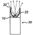
이롭게도, 상술된 램프 모듈들(10) 중 어떤 것이라도 조명 디바이스에 통합될 수 있는데, 그 예가 도 6a 및 도 6b에 개략적으로 도시되어 있다. 도 6a 및 도 6b의 조명 디바이스(30)는 반사기(32)를 지니며, 램프 모듈(10)은 이 반사기(32) 내에 위치한다. 도 6a에서, 램프 모듈(10)의 셀(22)은 투과 상태에 있어, 램프 모듈(10)로부터 방출되는 빛은 다소 협소한 광선 빔을 형성한다. 반면, 도 6b에서, 셀(22)은 산란(또는 굴절 또는 반사 또는 회절) 상태에 있어, 빛이 램프 모듈(10)을 빠져나갈 때 그 방향이 바뀐다. 광선 중 일부가 반사기(32)에 의해 반사될 수 있지만, 전반적으로 더 넓은 광선 빔이 생성된다. 따라서, 셀(22)을 전환함으로써 서로 다른 빔의 쉐이프가 제공될 수 있다. 여기서 빔은 램프 모듈(10)과 반사기(32)의 조합에 의해 쉐이핑될 수 있다. 조명 디바이스(30)는, 예를 들면, 토치 램프, 전조등, 라이플 램프, 다이빙 램프, 광부의 램프, 비상 상태 조명, 스포트라이트 또는 자전거 램프일 수 있다.Advantageously, any of the
셀(22) "위에" TIR-광학 기기(17)의 일부가 변경된 빛을 앞으로 향하게 할 수 있는 도 5a 및 도 5b에 개시된 램프 모듈과 같은, 고유의 "별도의" 빔 쉐이핑 수단(inherent "extra" beam shaping means)이 사용되는 램프 모듈의 경우, 또는 입사하는 빛의 방향을 이렇게 큰 각도로 바꾸지 않는 셀(22)이 사용되는 경우, 반사기(32)가 생략될 수 있음을 유의한다.Inherent "separate" beam shaping means, such as the lamp module disclosed in FIGS. 5A and 5B, where a portion of the TIR-
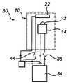
도 7 내지 도 9에 관련하여, 이전의 도면에 도시된 조명 디바이스(30)와 램 프 모듈(10)과 같은, 본 발명에 따른 조명 디바이스와 램프 모듈의 변형이 더 상세하게 설명되어 있다. 도 7에서, 조명 디바이스(30)는 상술된 것 중 임의의 유형의 램프 모듈(10)뿐만 아니라 이 램프 모듈(10)에 전력을 공급하기 위한 배터리(34)를 포함한다. 상술한 바와 같이, 램프 모듈은 LED 칩(12), LED 구동기(14) 및 전기적으로 전환가능한 셀(22)(그리고, 선택적으로, LED의 유형에 따라, 반사기, 광학 기기 등)을 포함한다. LED 구동기(14)는 라인(36a 및 36b)을 통해 배터리에 연결되고, LED 칩(12)은 라인(36a) 상에 제공되는 스위치(38)에 의해 가동될(actuated) 수 있다.With reference to FIGS. 7 to 9, modifications of the lighting device and the lamp module according to the invention, such as the
게다가, 셀(22)은 교류를 필요로 하고 배터리(34)는 직류를 공급하기 때문에, DC-AC 변환기(40)가 제공된다. 도 7에서, DC-AC 변환기(40)가 제공된다. DC-AC 변환기(40)는 한편으로는 셀(22)에 연결되고, 다른 한편으로는 라인(42a 및 42b)을 통해 배터리에 연결된다. 셀(22)을 턴 온/턴 오프할 수 있도록 하기 위해 라인(42a) 상에 제2 스위치(44)가 제공된다. 라인(42b)이 라인(36b)에서 분기하기 때문에, 이 구성은 램프 모듈(10)로부터 세 개의 접점(라인(36a, 36b 및 42a))을 필요로 한다.In addition, since the
따라서, 동작 시, LED 칩(12)은 스위치(38)에 의해 턴 온/턴 오프될 수 있고, 빔 쉐이핑 기능은 스위치(44)에 의해 턴 온/턴 오프될 수 있다. 다시 말하면, 사용자는 단지 스위치(44)를 활성화시킴으로써 빔 쉐이프를 바꿀 수 있는데, 스위치는 조명 디바이스에서 제공되는, 일반적인 푸시 버튼, 슬라이더 등일 수 있다.Thus, in operation, the
도 8은 도 7의 조명 디바이스의 변형을 도시하고 있는데, DC-AC 변환기(40) 가 램프 모듈(10) 내에 제공되는 대신, 램프 모듈의 외부에, 조명 디바이스(30)의 비 램프 모듈부에 장착된다. 이 구성에서는 램프 모듈(10)로부터 네 개의 접점을 필요로 하며, 그 외에는 도 7의 조명 디바이스와 동일하게 동작한다.FIG. 8 shows a variant of the lighting device of FIG. 7, where a DC-
도 9는 도 7의 조명 디바이스의 또 다른 변형을 도시하며, 램프 모듈(10)은 프로세서(46)를 더 포함한다. 프로세서(46)는 한편으로는 DC-AC 변환기(40)와 램프 모듈(10)의 LED 구동기(14)에 연결되고, 다른 한편으로는 라인(48a 및 48b)을 통해 조명 디바이스(30)의 배터리(34)에 연결된다. 단일의 스위치(50)가 배터리(34)와 프로세서(46) 사이의 라인(48a) 상에 제공된다. 스위치(50)에 의해, 사용자는 소정의 특성을 갖는 신호, 예를 들면, 소정의 지속 기간(duration), 소정의 시퀀스 및/또는 소정의 개수의 펄스를 갖는 신호를 생성할 수 있다. 이어서 프로세서(46)는, 소정의 신호 특성들을 셀(22) 및/또는 LED 칩(12)의 소정의 동작들로 변환하기(translate) 위한 소정의 명령어들을 포함한다. 예를 들면, 동작 시, 수신된 하나의 짧은 펄스는 프로세서(46)로 하여금 LED 칩(12)만을 활성화시키도록 할 수 있는 반면(그리하여 수집된 광선 빔을 생성함), 더 긴 단일의 펄스 또는 두 개의 짧은 펄스는 프로세서로 하여금 LED 칩(12)과 셀(22) 둘 다를 활성화시키도록 지시할 수 있다(그리하여 더 넓은 광선 빔을 생성함).9 shows another variant of the lighting device of FIG. 7, wherein the
따라서, 조명 디바이스(30)의 이 변형에서, 램프 모듈(10)은 두 개의 접점(라인(48a 및 48b))만을 필요로 하므로, 일반적인 2접점 플래시 조명(regular two-contact flash light)과 같은 기존의 통상적인 조명 디바이스에 쉽게 개장될 수 있다. 게다가, 빛(온/오프) 및 빔 쉐이프(더 넓은 것-더 협소한 것)는 조명 디바이 스(30)상의 하나의 스위치(50)에 의해 제어될 수 있어, 이것은 디바이스의 동작을 용이하게 한다.Thus, in this variant of the
대안으로, 램프 모듈(10)은 프로세서(46)와 유사하게 위치되는 전자 장치(electronics)(미도시)를 포함할 수 있는데, 이 전자 장치는 (배터리(34)로부터 시작되는) 가변 입력 전압을 LED 칩(12)에 공급되는 정 직류로 변환하도록 적응된다. 한편, 가변 입력 전압은 DC-AC 변환기(40)에 공급되고, 입력 전압에 따라 변하는 가변 교류가 셀(22)에 공급된다. 이에 의해, 입력 전압이 변하는 경우, LED 칩(12)의 세기는 일정하게 유지되지만, 서로 다른 전압이 셀을 스위치하기 때문에 빔의 쉐이프는 변한다. 이 해결책 또한 두 개의 접점만을 필요로 하므로, 예를 들면, 램프 모듈에 공급되는 전압이 (예를 들면, 조명 디바이스 상의 단일의 턴 놉(turn knob)에 의해) 조정가능한 플래시라이트에서와 같이, 응용물을 개장할 수 있다.In the alternative, the
당업자들은 본 발명이 상술된 바람직한 실시예에 결코 제한되지 않음을 이해할 것이다. 이와 대조적으로, 첨부된 청구항의 범위 내에서 많은 수정 및 변형이 가능하다. 예를 들면, 도 7 내지 도 9에 개시된 조명 디바이스들 중 임의의 조명 디바이스에 도 6a 및 도 6b에 개시된 반사기가 제공될 수 있고, 도 6a 및 도 6b의 조명 디바이스는 도 7 내지 도 9와 관련하여 기술된 임의의 유형의 것일 수 있다.Those skilled in the art will understand that the present invention is by no means limited to the preferred embodiments described above. In contrast, many modifications and variations are possible within the scope of the appended claims. For example, any of the lighting devices disclosed in FIGS. 7-9 may be provided with the reflector disclosed in FIGS. 6A and 6B, and the lighting devices of FIGS. 6A-6B relate to FIGS. 7-9. It may be of any type described.
또한, 단 하나의 LED 칩(12)을 갖는 램프 모듈이 상술되었지만, 램프 모듈이 예를 들면, 서로 다른 컬러의 빛을 방출하는 LED 칩들과 같은 여러 개의 LED 칩을 포함할 수 있음을 이해할 것이다. LED 칩(들)은 또한 LED 칩으로부터 방출되는 빛 을 예를 들면 흰색으로 변환하기 위해 인(phosphor)으로 코팅될 수 있다(즉, 소위 인 변환된 LED).In addition, although a lamp module having only one
또한, 도 6a 및 도 6b의 반사기(32) 대신, TIR-광학 기기, 또는 굴절 또는 반사 엘리멘트, 또는 그 조합과 같은, 다른 빔 쉐이핑 엘리먼트들이 사용될 수 있다.Also, instead of the
Claims (15)
Translated fromKoreanApplications Claiming Priority (3)
| Application Number | Priority Date | Filing Date | Title |
|---|---|---|---|
| EP06100359 | 2006-01-16 | ||
| EP06100359.6 | 2006-01-16 | ||
| PCT/IB2007/050074WO2007080543A1 (en) | 2006-01-16 | 2007-01-10 | Lamp module and lighting device comprising such a lamp module |
Publications (2)
| Publication Number | Publication Date |
|---|---|
| KR20080096542A KR20080096542A (en) | 2008-10-30 |
| KR101333023B1true KR101333023B1 (en) | 2013-11-26 |
Family
ID=37865876
Family Applications (1)
| Application Number | Title | Priority Date | Filing Date |
|---|---|---|---|
| KR1020087020001AExpired - Fee RelatedKR101333023B1 (en) | 2006-01-16 | 2007-01-10 | Lamp module and lighting device comprising such a lamp module |
Country Status (7)
| Country | Link |
|---|---|
| US (1) | US8042967B2 (en) |
| EP (1) | EP1979672B1 (en) |
| JP (1) | JP5283510B2 (en) |
| KR (1) | KR101333023B1 (en) |
| CN (1) | CN101371073B (en) |
| TW (1) | TWI416036B (en) |
| WO (1) | WO2007080543A1 (en) |
Families Citing this family (36)
| Publication number | Priority date | Publication date | Assignee | Title |
|---|---|---|---|---|
| US8656622B2 (en) | 2007-10-11 | 2014-02-25 | Ashbury International Group, Inc. | Tactical firearm systems and methods of manufacturing same |
| US10215529B2 (en)* | 2009-01-16 | 2019-02-26 | Prototype Productions Incorporated Ventures Two, Llc | Accessory mount for rifle accessory rail, communication, and power transfer system—accessory attachment |
| US8397418B2 (en) | 2009-01-16 | 2013-03-19 | Prototype Productions Incorporated Ventures Two, Llc | System for providing electrical power to accessories mounted on the powered |
| DE102009007496A1 (en)* | 2009-02-05 | 2010-08-19 | E:Cue Control Gmbh | lamp |
| CN101852340B (en)* | 2009-03-31 | 2012-05-30 | 海洋王照明科技股份有限公司 | Portable floodlight-condensing lamp |
| CN102109107A (en)* | 2009-12-25 | 2011-06-29 | 富准精密工业(深圳)有限公司 | Light emitting diode lamp |
| US10477618B2 (en) | 2010-01-15 | 2019-11-12 | Colt Canada Ip Holding Partnership | Networked battle system or firearm |
| US10477619B2 (en) | 2010-01-15 | 2019-11-12 | Colt Canada Ip Holding Partnership | Networked battle system or firearm |
| US10470010B2 (en) | 2010-01-15 | 2019-11-05 | Colt Canada Ip Holding Partnership | Networked battle system or firearm |
| US10337834B2 (en) | 2010-01-15 | 2019-07-02 | Colt Canada Ip Holding Partnership | Networked battle system or firearm |
| US9823043B2 (en)* | 2010-01-15 | 2017-11-21 | Colt Canada Ip Holding Partnership | Rail for inductively powering firearm accessories |
| US9921028B2 (en) | 2010-01-15 | 2018-03-20 | Colt Canada Ip Holding Partnership | Apparatus and method for powering and networking a rail of a firearm |
| KR101370920B1 (en)* | 2010-06-23 | 2014-03-07 | 엘지전자 주식회사 | Lighting device |
| US10955109B1 (en)* | 2010-07-07 | 2021-03-23 | Courtney Joseph Monzyk | Portable lighting device |
| DE102010034774A1 (en)* | 2010-08-18 | 2012-02-23 | Trilux Gmbh & Co. Kg | Lamp e.g. busbar lamp, for lighting working station, has lighting arrangement comprising two set of lighting units, where one of set of lighting units is arranged before other set of lighting units with respect to main radiation direction |
| DK3165868T3 (en) | 2011-02-15 | 2018-11-26 | Colt Canada Ip Holding Partnership | Apparatus and method for inductive power supply and network connection of a firearm's rail |
| US8469559B2 (en) | 2011-03-28 | 2013-06-25 | Target Brands, Inc. | Edge-lit lighting product |
| USD663472S1 (en) | 2011-03-28 | 2012-07-10 | Target Brands, Inc. | Luminaire |
| WO2012150945A1 (en)* | 2011-05-05 | 2012-11-08 | Koepf Gerhard A | Beam multiplier for multi-led lighting assemblies |
| KR20130045687A (en)* | 2011-10-26 | 2013-05-06 | 엘지이노텍 주식회사 | Light emitting apparatus and lighting apparatus |
| CN104246358B (en)* | 2012-03-12 | 2018-04-06 | 飞利浦照明控股有限公司 | remote beam shaping |
| US9392651B2 (en) | 2012-04-11 | 2016-07-12 | Koninklijke Philips N.V. | Lighting methods and apparatus with selectively applied face lighting component |
| PL3330606T3 (en)* | 2012-04-20 | 2022-11-21 | Signify Holding B.V. | Controllable lighting by time multiplexing switchable optical elements |
| CA2881982C (en) | 2012-08-16 | 2020-10-13 | Colt Canada Corporation | Apparatus and method for powering and networking a rail of a firearm |
| DE102013108800B4 (en) | 2013-08-14 | 2015-09-03 | Sick Ag | Lighting device and method for generating a lighting field |
| FR3017692A1 (en)* | 2014-02-14 | 2015-08-21 | Zedel | PORTABLE LAMP COMPRISING A DEVICE FOR ELECTRICALLY CONTROLLING THE GEOMETRY OF THE ELECTRICAL BEAM |
| US9841167B2 (en) | 2014-09-25 | 2017-12-12 | GE Lighting Solutions, LLC | Lighting system with actively controllable optics and method |
| KR20170078809A (en)* | 2014-11-07 | 2017-07-07 | 쓰리엠 이노베이티브 프로퍼티즈 컴파니 | Lighting component including switchable diffuser |
| US10126607B2 (en) | 2015-09-12 | 2018-11-13 | Lensvector Inc. | Liquid crystal beam control device |
| WO2018045469A1 (en)* | 2016-09-08 | 2018-03-15 | Lensvector Inc. | Liquid crystal dynamic beam control device and manufacture |
| WO2018053640A1 (en)* | 2016-09-22 | 2018-03-29 | Lensvector Inc. | Liquid crystal beam control device generating flat-top distribution |
| CA3063839A1 (en) | 2017-05-15 | 2018-11-22 | T-Worx Holdings, LLC | Power system for a firearm |
| CA3063897A1 (en) | 2017-05-15 | 2018-11-22 | T-Worx Holdings, LLC | System and method for networking firearm-mounted devices |
| US10697615B1 (en)* | 2018-05-08 | 2020-06-30 | Elite Lighting | Light fixture with LCD optic element |
| DE102018128979A1 (en)* | 2018-11-19 | 2020-05-20 | Trilux Gmbh & Co. Kg | Luminaire with variable radiation characteristics |
| CN113037968A (en)* | 2021-03-01 | 2021-06-25 | 维沃移动通信有限公司 | Electronic device |
Citations (4)
| Publication number | Priority date | Publication date | Assignee | Title |
|---|---|---|---|---|
| JP2002231002A (en)* | 2001-01-31 | 2002-08-16 | Rabo Sufia Kk | Lighting device |
| JP2004527889A (en)* | 2001-05-25 | 2004-09-09 | イルメ エル.エル.シー. | Lamp masking method and apparatus |
| JP2004296249A (en)* | 2003-03-26 | 2004-10-21 | Matsushita Electric Works Ltd | Luminaire |
| JP2005183327A (en)* | 2003-12-24 | 2005-07-07 | Stanley Electric Co Ltd | Vehicle headlamp |
Family Cites Families (22)
| Publication number | Priority date | Publication date | Assignee | Title |
|---|---|---|---|---|
| US4570204A (en) | 1985-02-13 | 1986-02-11 | Mine Safety Appliances Company | Adjustable focus lamp |
| JPS6321633A (en)* | 1986-07-15 | 1988-01-29 | Stanley Electric Co Ltd | Varying device for irradiation angle of projector |
| US5161879A (en) | 1991-04-10 | 1992-11-10 | Mcdermott Kevin | Flashlight for covert applications |
| US5424927A (en)* | 1991-06-27 | 1995-06-13 | Rayovac Corporation | Electro-optic flashlight electro-optically controlling the emitted light |
| US5412492A (en) | 1991-11-05 | 1995-05-02 | Magnascreen Corporation | Electro-optical lens assembly |
| US6062702A (en) | 1997-04-16 | 2000-05-16 | Krietzman; Mark Howard | Laser light |
| DE19937852C2 (en) | 1999-08-13 | 2002-05-29 | Thomas Strobl | Portable lamp and its use |
| US6357893B1 (en) | 2000-03-15 | 2002-03-19 | Richard S. Belliveau | Lighting devices using a plurality of light sources |
| US6474837B1 (en) | 2000-11-20 | 2002-11-05 | Richard S. Belliveau | Lighting device with beam altering mechanism incorporating a plurality of light souces |
| US6607286B2 (en) | 2001-05-04 | 2003-08-19 | Lumileds Lighting, U.S., Llc | Lens and lens cap with sawtooth portion for light emitting diode |
| CN2546734Y (en)* | 2002-04-29 | 2003-04-23 | 青岛海洋大学 | White light luminous diode lighting emergency lamp |
| DE10233719A1 (en)* | 2002-07-24 | 2004-02-05 | Bayerische Motoren Werke Ag | Light, especially for motor vehicle has light source(s), cover in light radiation direction with electrical diffuser whose optical action can be varied to produce multiple functionality of light |
| AU2003281967A1 (en) | 2002-11-19 | 2004-06-15 | Dan Friis | Lighting body or source of light based on light-emitting diodes |
| EP1422467A3 (en) | 2002-11-22 | 2006-10-25 | Mellert SLT GmbH & Co. KG | Mobile lamp |
| US6964507B2 (en) | 2003-04-25 | 2005-11-15 | Everbrite, Llc | Sign illumination system |
| JP4621681B2 (en) | 2003-06-10 | 2011-01-26 | イルミネーション マネジメント ソリューションズ インコーポレイテッド | Improved LED lighting module |
| US6921181B2 (en)* | 2003-07-07 | 2005-07-26 | Mei-Feng Yen | Flashlight with heat-dissipation device |
| CN2674264Y (en)* | 2003-12-19 | 2005-01-26 | 汤铁 | Illuminating device and mated lamp base |
| JP4471729B2 (en)* | 2004-04-30 | 2010-06-02 | シチズン電子株式会社 | Light emitting device with liquid crystal lens |
| WO2005121641A1 (en)* | 2004-06-11 | 2005-12-22 | Koninklijke Philips Electronics N.V. | Illumination system |
| DE202004009836U1 (en) | 2004-06-23 | 2004-08-19 | Dedo Weigert Film Gmbh | LED device with variable beam angle |
| TWM274490U (en)* | 2005-03-30 | 2005-09-01 | Yin-Cheng Su | Lampshade capable of adjusting light direction |
- 2007
- 2007-01-10KRKR1020087020001Apatent/KR101333023B1/ennot_activeExpired - Fee Related
- 2007-01-10WOPCT/IB2007/050074patent/WO2007080543A1/enactiveApplication Filing
- 2007-01-10USUS12/160,914patent/US8042967B2/enactiveActive
- 2007-01-10CNCN2007800024682Apatent/CN101371073B/enactiveActive
- 2007-01-10EPEP07700563.5Apatent/EP1979672B1/enactiveActive
- 2007-01-10JPJP2008549961Apatent/JP5283510B2/enactiveActive
- 2007-01-12TWTW096101272Apatent/TWI416036B/enactive
Patent Citations (4)
| Publication number | Priority date | Publication date | Assignee | Title |
|---|---|---|---|---|
| JP2002231002A (en)* | 2001-01-31 | 2002-08-16 | Rabo Sufia Kk | Lighting device |
| JP2004527889A (en)* | 2001-05-25 | 2004-09-09 | イルメ エル.エル.シー. | Lamp masking method and apparatus |
| JP2004296249A (en)* | 2003-03-26 | 2004-10-21 | Matsushita Electric Works Ltd | Luminaire |
| JP2005183327A (en)* | 2003-12-24 | 2005-07-07 | Stanley Electric Co Ltd | Vehicle headlamp |
Also Published As
| Publication number | Publication date |
|---|---|
| CN101371073B (en) | 2010-06-09 |
| TW200745486A (en) | 2007-12-16 |
| US8042967B2 (en) | 2011-10-25 |
| JP5283510B2 (en) | 2013-09-04 |
| TWI416036B (en) | 2013-11-21 |
| CN101371073A (en) | 2009-02-18 |
| EP1979672A1 (en) | 2008-10-15 |
| EP1979672B1 (en) | 2017-09-13 |
| JP2009524180A (en) | 2009-06-25 |
| WO2007080543A1 (en) | 2007-07-19 |
| US20100148688A1 (en) | 2010-06-17 |
| KR20080096542A (en) | 2008-10-30 |
Similar Documents
| Publication | Publication Date | Title |
|---|---|---|
| KR101333023B1 (en) | Lamp module and lighting device comprising such a lamp module | |
| CN216010470U (en) | high visibility headlights | |
| US10563844B2 (en) | Configurable luminaire with light sources variably oriented with respect to an array of concave mirrors | |
| CN1806145B (en) | Improved LED flashlight | |
| US7520645B2 (en) | Vehicular headlamp and car headlamp | |
| US7178937B2 (en) | Lighting device and method for lighting | |
| US10794550B2 (en) | Multi-directional flashlight | |
| WO2007099860A1 (en) | Led illumination device | |
| US7318662B2 (en) | Vehicular headlamp | |
| JP2004296249A (en) | Luminaire | |
| US20140153255A1 (en) | Luminaire | |
| KR101236737B1 (en) | Aspherical lens for a light emitting diode and light source assembly including the same | |
| KR101529166B1 (en) | Lamp for vehicle | |
| KR20090001671U (en) | LED Lamp for Spotlight | |
| KR200478356Y1 (en) | LED Flashlight | |
| KR100772922B1 (en) | LED luminaire with light guide diffusion means | |
| TW201100721A (en) | LED linear reflection lighting | |
| KR200425781Y1 (en) | Focusable LED Flashlight | |
| KR101509460B1 (en) | Led lighting | |
| EP3845800B1 (en) | Vehicle lamp using semiconductor light-emitting device | |
| KR20150138886A (en) | Led lighting device | |
| KR101491114B1 (en) | LED lamp | |
| KR101252689B1 (en) | LED lamp | |
| KR101167044B1 (en) | Security light fixture with reflector | |
| JP2007265935A (en) | Led flashlight, and multiple focal lens flashlight which are characterized by having a plurality of dispersed foci between 50cm and 2m from light source |
Legal Events
| Date | Code | Title | Description |
|---|---|---|---|
| PA0105 | International application | St.27 status event code:A-0-1-A10-A15-nap-PA0105 | |
| P11-X000 | Amendment of application requested | St.27 status event code:A-2-2-P10-P11-nap-X000 | |
| P13-X000 | Application amended | St.27 status event code:A-2-2-P10-P13-nap-X000 | |
| PG1501 | Laying open of application | St.27 status event code:A-1-1-Q10-Q12-nap-PG1501 | |
| A201 | Request for examination | ||
| P11-X000 | Amendment of application requested | St.27 status event code:A-2-2-P10-P11-nap-X000 | |
| P13-X000 | Application amended | St.27 status event code:A-2-2-P10-P13-nap-X000 | |
| PA0201 | Request for examination | St.27 status event code:A-1-2-D10-D11-exm-PA0201 | |
| E902 | Notification of reason for refusal | ||
| PE0902 | Notice of grounds for rejection | St.27 status event code:A-1-2-D10-D21-exm-PE0902 | |
| R18-X000 | Changes to party contact information recorded | St.27 status event code:A-3-3-R10-R18-oth-X000 | |
| E13-X000 | Pre-grant limitation requested | St.27 status event code:A-2-3-E10-E13-lim-X000 | |
| P11-X000 | Amendment of application requested | St.27 status event code:A-2-2-P10-P11-nap-X000 | |
| P13-X000 | Application amended | St.27 status event code:A-2-2-P10-P13-nap-X000 | |
| E701 | Decision to grant or registration of patent right | ||
| PE0701 | Decision of registration | St.27 status event code:A-1-2-D10-D22-exm-PE0701 | |
| GRNT | Written decision to grant | ||
| PR0701 | Registration of establishment | St.27 status event code:A-2-4-F10-F11-exm-PR0701 | |
| PR1002 | Payment of registration fee | St.27 status event code:A-2-2-U10-U12-oth-PR1002 Fee payment year number:1 | |
| PG1601 | Publication of registration | St.27 status event code:A-4-4-Q10-Q13-nap-PG1601 | |
| FPAY | Annual fee payment | Payment date:20161115 Year of fee payment:4 | |
| PR1001 | Payment of annual fee | St.27 status event code:A-4-4-U10-U11-oth-PR1001 Fee payment year number:4 | |
| PN2301 | Change of applicant | St.27 status event code:A-5-5-R10-R11-asn-PN2301 | |
| PN2301 | Change of applicant | St.27 status event code:A-5-5-R10-R11-asn-PN2301 | |
| PN2301 | Change of applicant | St.27 status event code:A-5-5-R10-R14-asn-PN2301 | |
| FPAY | Annual fee payment | Payment date:20171110 Year of fee payment:5 | |
| PR1001 | Payment of annual fee | St.27 status event code:A-4-4-U10-U11-oth-PR1001 Fee payment year number:5 | |
| FPAY | Annual fee payment | Payment date:20181108 Year of fee payment:6 | |
| PR1001 | Payment of annual fee | St.27 status event code:A-4-4-U10-U11-oth-PR1001 Fee payment year number:6 | |
| P22-X000 | Classification modified | St.27 status event code:A-4-4-P10-P22-nap-X000 | |
| R18-X000 | Changes to party contact information recorded | St.27 status event code:A-5-5-R10-R18-oth-X000 | |
| FPAY | Annual fee payment | Payment date:20191108 Year of fee payment:7 | |
| PR1001 | Payment of annual fee | St.27 status event code:A-4-4-U10-U11-oth-PR1001 Fee payment year number:7 | |
| PR1001 | Payment of annual fee | St.27 status event code:A-4-4-U10-U11-oth-PR1001 Fee payment year number:8 | |
| PR1001 | Payment of annual fee | St.27 status event code:A-4-4-U10-U11-oth-PR1001 Fee payment year number:9 | |
| R18-X000 | Changes to party contact information recorded | St.27 status event code:A-5-5-R10-R18-oth-X000 | |
| PR1001 | Payment of annual fee | St.27 status event code:A-4-4-U10-U11-oth-PR1001 Fee payment year number:10 | |
| PR1001 | Payment of annual fee | St.27 status event code:A-4-4-U10-U11-oth-PR1001 Fee payment year number:11 | |
| PC1903 | Unpaid annual fee | St.27 status event code:A-4-4-U10-U13-oth-PC1903 Not in force date:20241121 Payment event data comment text:Termination Category : DEFAULT_OF_REGISTRATION_FEE | |
| PC1903 | Unpaid annual fee | St.27 status event code:N-4-6-H10-H13-oth-PC1903 Ip right cessation event data comment text:Termination Category : DEFAULT_OF_REGISTRATION_FEE Not in force date:20241121 |