KR101330735B1 - Robot cleaner - Google Patents
Robot cleanerDownload PDFInfo
- Publication number
- KR101330735B1 KR101330735B1KR1020070104300AKR20070104300AKR101330735B1KR 101330735 B1KR101330735 B1KR 101330735B1KR 1020070104300 AKR1020070104300 AKR 1020070104300AKR 20070104300 AKR20070104300 AKR 20070104300AKR 101330735 B1KR101330735 B1KR 101330735B1
- Authority
- KR
- South Korea
- Prior art keywords
- main body
- dust
- stopper
- suction port
- dust container
- Prior art date
- Legal status (The legal status is an assumption and is not a legal conclusion. Google has not performed a legal analysis and makes no representation as to the accuracy of the status listed.)
- Expired - Fee Related
Links
Images


Classifications
- A—HUMAN NECESSITIES
- A47—FURNITURE; DOMESTIC ARTICLES OR APPLIANCES; COFFEE MILLS; SPICE MILLS; SUCTION CLEANERS IN GENERAL
- A47L—DOMESTIC WASHING OR CLEANING; SUCTION CLEANERS IN GENERAL
- A47L9/00—Details or accessories of suction cleaners, e.g. mechanical means for controlling the suction or for effecting pulsating action; Storing devices specially adapted to suction cleaners or parts thereof; Carrying-vehicles specially adapted for suction cleaners
- A47L9/28—Installation of the electric equipment, e.g. adaptation or attachment to the suction cleaner; Controlling suction cleaners by electric means
- A—HUMAN NECESSITIES
- A47—FURNITURE; DOMESTIC ARTICLES OR APPLIANCES; COFFEE MILLS; SPICE MILLS; SUCTION CLEANERS IN GENERAL
- A47L—DOMESTIC WASHING OR CLEANING; SUCTION CLEANERS IN GENERAL
- A47L9/00—Details or accessories of suction cleaners, e.g. mechanical means for controlling the suction or for effecting pulsating action; Storing devices specially adapted to suction cleaners or parts thereof; Carrying-vehicles specially adapted for suction cleaners
- A47L9/10—Filters; Dust separators; Dust removal; Automatic exchange of filters
- A47L9/14—Bags or the like; Rigid filtering receptacles; Attachment of, or closures for, bags or receptacles
- A47L9/1427—Means for mounting or attaching bags or filtering receptacles in suction cleaners; Adapters
- A47L9/1463—Means for mounting or attaching bags or filtering receptacles in suction cleaners; Adapters specially adapted for rigid filtering receptacles
- A—HUMAN NECESSITIES
- A47—FURNITURE; DOMESTIC ARTICLES OR APPLIANCES; COFFEE MILLS; SPICE MILLS; SUCTION CLEANERS IN GENERAL
- A47L—DOMESTIC WASHING OR CLEANING; SUCTION CLEANERS IN GENERAL
- A47L11/00—Machines for cleaning floors, carpets, furniture, walls, or wall coverings
- A47L11/24—Floor-sweeping machines, motor-driven
- A—HUMAN NECESSITIES
- A47—FURNITURE; DOMESTIC ARTICLES OR APPLIANCES; COFFEE MILLS; SPICE MILLS; SUCTION CLEANERS IN GENERAL
- A47L—DOMESTIC WASHING OR CLEANING; SUCTION CLEANERS IN GENERAL
- A47L9/00—Details or accessories of suction cleaners, e.g. mechanical means for controlling the suction or for effecting pulsating action; Storing devices specially adapted to suction cleaners or parts thereof; Carrying-vehicles specially adapted for suction cleaners
- A—HUMAN NECESSITIES
- A47—FURNITURE; DOMESTIC ARTICLES OR APPLIANCES; COFFEE MILLS; SPICE MILLS; SUCTION CLEANERS IN GENERAL
- A47L—DOMESTIC WASHING OR CLEANING; SUCTION CLEANERS IN GENERAL
- A47L2201/00—Robotic cleaning machines, i.e. with automatic control of the travelling movement or the cleaning operation
Landscapes
- Engineering & Computer Science (AREA)
- Mechanical Engineering (AREA)
- Nozzles For Electric Vacuum Cleaners (AREA)
- Filters For Electric Vacuum Cleaners (AREA)
Abstract
Translated fromKoreanDescription
Translated fromKorean도 1은 본 발명의 바람직한 실시예에 따른 로봇청소기의 전체적인 구성을 나타내는 단면도이다.1 is a cross-sectional view showing the overall configuration of a robot cleaner according to a preferred embodiment of the present invention.
도2는 본 발명의 바람직한 실시예에 따른 로봇청소기의 본체와 먼지통의 분리사시도이다.Figure 2 is an exploded perspective view of the main body and dust container of the robot vacuum cleaner according to a preferred embodiment of the present invention.
도 3은 본 발명의 바람직한 실시예에 따른 로봇청소기의 요부를 나타내는 측면도이다.3 is a side view showing the main portion of the robot cleaner according to a preferred embodiment of the present invention.
도 4,5는 본 발명의 바람직한 실시예에 따른 로봇청소기의 먼지통 결합상태의 역류방지장치의 동작을 나타내는 요부사시도이다.4 and 5 is a perspective view showing the operation of the backflow prevention device of the dust container coupled state of the robot cleaner according to a preferred embodiment of the present invention.
도 6,7은 본 발명의 바람직한 실시예에 따른 로봇청소기를 들어올리는 경우 역류방지장치의 동작을 나타내는 요부사시도이다.6 and 7 is a perspective view showing the operation of the backflow prevention device when lifting the robot cleaner according to a preferred embodiment of the present invention.
*도면의 주요부분에 대한 부호 설명*Description of the Related Art [0002]
10 : 본체12b : 후방보조바퀴10:
13 : 개구부14 : 회전브러쉬장치13: opening 14: rotary brush device
20 : 송풍장치30 : 먼지통20: blower 30: dust box
31 : 포집부32 : 흡입구31: collecting part 32: suction port
50 : 셔터부52 : 개폐판50: shutter unit 52: opening and closing plate
53 : 레버부54 : 탄성부재53
60 : 스토퍼부70 : 후방보조바퀴유닛60: stopper part 70: rear auxiliary wheel unit
72,73 : 제1,2가이드로드74 : 스토퍼지지부72,73: first and second guide rod 74: stopper support
75 : 스프링.75: spring.
본 발명은 로봇청소기에 관한 것으로, 특히 먼지통 내의 먼지가 외부로 쏟아지는 것을 방지할 수 있는 로봇청소기에 관한 것이다.The present invention relates to a robot cleaner, and more particularly, to a robot cleaner capable of preventing the dust in the dust container from spilling to the outside.
청소기는 이물질을 제거하여 실내를 청결하게 하는 기구로서, 저압부의 흡입력을 이용하여 이물질을 빨아들이는 진공청소기가 일반적으로 사용된다.A vacuum cleaner is a device that cleans a room by removing foreign substances, and a vacuum cleaner that sucks foreign substances by using suction force of a low pressure part is generally used.
근래에는 사용자의 노동력없이 자동 주행 기능을 통해 스스로 이동하면서 실내 바닥으로부터 이물질을 제거하는 로봇청소기가 개발되고 있다.Recently, a robot cleaner has been developed to remove foreign substances from the indoor floor while moving by itself through an automatic driving function without a user's labor.
이러한 로봇 청소기의 일 예는 먼지나 오물을 흡입하는 흡입구와 공기를 배출하는 배기구가 형성되어 있는 본체 케이스와, 그 본체케이스의 내측에 설치되어 흡입력을 발생시키기 위한 팬모터와, 팬모터의 전방에 설치되어 팬모터에 의해 흡입되는 먼지나 오물을 포집하기 위한 먼지통과, 본체 케이스의 하측에 구비되어 먼지통과 연결통로로 연결되고 바닥의 먼지나 이물질을 흡입하기 위한 흡입헤드와, 그 흡입헤드의 내부에 회전 가능하게 배치되어 바닥에 부착되어있는 먼지나 이물질을 쓸어내기 위한 브러쉬를 포함하여 이루어진다.An example of such a robot cleaner is a main body case having an inlet for sucking dust and dirt and an exhaust port for discharging air, a fan motor installed inside the main body case for generating suction force, and a fan motor in front of the fan motor. A dust box installed to collect dust and dirt sucked by the fan motor, a suction head provided at the lower side of the main body case, connected to the dust container and a connection path, and suctioning dust or foreign matter from the floor, and inside of the suction head It is rotatably disposed on the floor and comprises a brush for sweeping out dust or foreign matter attached to the floor.
그러나, 이러한 종래의 로봇청소기는 사용자가 본체를 들거나, 경사지게 위치시키는 경우 먼지통에 포집된 먼지가 외부로 쏟아질 수 있는 문제점이 있다.However, such a conventional robot cleaner has a problem that dust collected in the dust container can be poured out when the user lifts the main body or places it inclined.
이러한 문제점을 해결하기 위한 청소기의 일 예가 대한민국등록실용신안 등록번호 제20-335861호에 개시된다.An example of a cleaner for solving this problem is disclosed in Korean Utility Model Registration No. 20-335861.
상기 공보에 개시된 청소기는 인입구로부터 소정 길이로 형성된 안내부의 끝단에 단턱이 형성되어 인입되는 쓰레기가 저장될 수 있도록 소정의 수용공간이 형성된 청소기용 집진기의 역류방지구조에 있어서, 안내부의 하부에 밀착되어 하우징의 기울임 각도에 따라 수평상태와 자유회전이 될 수 있도록 안내부의 측벽에 힌지 결합되는 역류방지판을 포함한다.The vacuum cleaner disclosed in the above publication has a stepped portion formed at the end of the guide part having a predetermined length from the inlet, and in the backflow prevention structure of the dust collector for the cleaner having a predetermined accommodation space for storing the incoming garbage, the vacuum cleaner is closely attached to the lower part of the guide part. It includes a non-return plate hinged to the side wall of the guide to be horizontal and free rotation according to the inclination angle of the housing.
따라서 집진기에 수용된 쓰레기 및 먼지가 사용자의 의도와는 다른 상황에서 집진기로부터 배출되는 문제를 해결하여 자유롭게 청소기를 움직이거나 이동시킬 수 있다.Therefore, it is possible to freely move or move the cleaner by solving the problem that the garbage and dust accommodated in the dust collector is discharged from the dust collector in a situation different from the user's intention.
그러나 상기 공보에 개시된 청소기의 역류방지구조는 역류방지판이 개폐되는 경로에 먼지 등의 이물질이 있는 경우 역류방지판의 개폐가 불가능한 문제점이 있으며, 사용자가 대략 수평을 유지하면서 청소기를 들어 올려 이동시키는 경우 역류방지판이 개방된 상태를 유지하기 때문에 먼지 등이 배출될 가능성이 있다.However, the backflow prevention structure of the cleaner disclosed in the above publication has a problem that opening and closing of the backflow prevention plate is impossible when there are foreign substances such as dust in the path of the backflow prevention plate opening and closing, while the user lifts and moves the cleaner while keeping the level approximately. Since the non-return plate is kept open, dust and the like may be discharged.
따라서, 본 발명은 상기와 같은 종래의 문제점을 해결하기 위한 것으로, 본 발명의 목적은 먼지통내 먼지 등이 유출될 가능성이 있는 상황에서 먼지통내에 포집된 먼지가 외부로 쏟아지는 것을 방지할 수 있는 로봇청소기를 제공하는 것이다.Therefore, the present invention is to solve the conventional problems as described above, the object of the present invention is a robot cleaner that can prevent the dust collected in the dust container to be poured out in the situation that the dust in the dust container and the like may leak. To provide.
또한 본 발명의 다른 목적은 먼지통을 본체에서 분리하는 경우 먼지통내의 먼지가 쏟아지는 것을 방지할 수 있는 로봇청소기를 제공하는 것이다.In addition, another object of the present invention is to provide a robot cleaner that can prevent the dust in the dust container from spilling when separating the dust container from the main body.
또한, 본 발명의 또 다른 목적은 먼지통이 장착된 본체를 사용자가 들고 이동하는 경우에도 먼지통내의 먼지가 쏟아지는 것을 방지할 수 있는 로봇청소기를 제공하는 것이다.In addition, another object of the present invention is to provide a robot cleaner that can prevent the dust in the dust container from spilling even when the user carrying the body equipped with the dust container.
상기 목적을 달성하기 위하여 본 발명은 본체와, 상기 본체에 마련되어 먼지 등을 포집하기 위한 먼지통과, 상기 먼지통의 흡입구를 통해 먼지 등이 외부로 역류하는 것을 방지하기 위한 역류방지장치를 구비하고, 상기 역류방지장치는 상기 흡입구를 개폐하는 셔터부와, 상기 셔터부를 구동시키는 스토퍼부를 구비하는 것을 특징으로 한다.In order to achieve the above object, the present invention includes a main body, a dust container provided on the main body to collect dust and the like, and a backflow preventing device for preventing the dust or the like from flowing backward through the suction port of the dust container. The non-return device may include a shutter unit for opening and closing the suction port and a stopper unit for driving the shutter unit.
또한, 상기 셔터부는 상기 흡입구측에 회전 가능하게 고정되는 개폐판과, 상기 개폐판을 회전시키기 위한 레버부와, 상기 개폐판이 상기 흡입구를 폐쇄한 상태로 탄성력을 제공하는 탄성부재를 포함한다.The shutter unit may include an opening and closing plate rotatably fixed to the suction port side, a lever unit for rotating the opening and closing plate, and an elastic member for providing an elastic force in a state in which the opening and closing plate closes the suction port.
또한, 상기 스토퍼부는 상기 레버부를 가압 회전시켜 상기 개폐판을 개방하고 상기 레버부의 가압을 해제하여 상기 개폐판을 폐쇄한다.In addition, the stopper part presses and rotates the lever part to open the opening and closing plate, and releases the pressurization of the lever part to close the opening and closing plate.
또한, 상기 먼지통은 상기 본체에 착탈 가능하게 결합하고, 상기 먼지통의 착탈과 연동하여 상기 셔터부가 상기 흡입구를 개폐한다.In addition, the dust container is detachably coupled to the main body, and the shutter unit opens and closes the suction port in conjunction with the detachment of the dust container.
또한, 상기 역류방지장치는 상기 스토퍼부가 회전하게 하거나 회전을 제한하는 스토퍼지지부를 더 포함한다.In addition, the backflow prevention device further includes a stopper support portion for allowing the stopper portion to rotate or limit rotation.
또한, 상기 본체는 보조바퀴유닛을 더 포함하고, 상기 스토퍼지지부는 상기 보조바퀴유닛에 작용하는 하중에 따라 상하이동 가능하도록 마련되고, 상기 셔터부는 상기 스토퍼지지부의 상하이동과 연동하여 상기 흡입구를 개폐한다.The main body further includes an auxiliary wheel unit, wherein the stopper support part is provided to be movable in accordance with a load acting on the auxiliary wheel unit, and the shutter unit is connected to the stopper of the stopper support part to open and close the suction port. do.
또한, 상기 보조바퀴유닛은 보조바퀴와, 상기 보조바퀴의 상하 이동을 가이 드하는 가이드로드와, 상기 보조바퀴를 탄성 지지하도록 상기 가이드로드에 마련된 스프링을 포함하고, 상기 스토퍼지지부는 상기 가이드로드에 마련된다.The auxiliary wheel unit may include an auxiliary wheel, a guide rod for guiding the up and down movement of the auxiliary wheel, and a spring provided on the guide rod to elastically support the auxiliary wheel, and the stopper support part may be provided on the guide rod. Prepared.
그리고, 다른 측면에서 바라본 본 발명은 본체와, 상기 본체에 착탈 가능하게 마련되며 먼지 등을 포집하기 위한 먼지통과, 상기 먼지통의 흡입구를 통해 먼지 등이 외부로 역류하는 것을 방지하기 위한 역류방지장치를 구비하고, 상기 역류방지장치는 상기 흡입구에 개폐 가능하게 마련된 셔터부와, 상기 먼지통의 착탈과 연동하여 상기 셔터부를 회동시키는 스토퍼부를 포함하는 것을 특징으로 한다.In another aspect, the present invention provides a main body, a dust container detachably provided to the main body, a dust container for collecting dust, and a backflow preventing device for preventing dust from flowing back to the outside through an inlet of the dust container. And the backflow prevention device includes a shutter unit provided to open and close at the suction port, and a stopper unit rotating the shutter unit in association with detachment of the dust container.
또한, 상기 역류방지장치는 상기 셔터부를 회동시키도록 상기 스토퍼부의 소정위치를 지지하는 스토퍼지지부를 더 포함한다.The backflow prevention device further includes a stopper support part for supporting a predetermined position of the stopper part to rotate the shutter part.
그리고 또 다른 측면에서 바라본 본 발명은 본체와, 상기 본체에 마련되어 먼지 등을 포집하기 위한 먼지통과, 상기 먼지통의 흡입구를 통해 먼지 등이 외부로 역류하는 것을 방지하기 위한 역류방지장치를 구비하고, 상기 역류방지장치는 상기 흡입구에 개폐 가능하게 마련된 셔터부와, 상기 본체의 상하이동과 연동하여 상기 셔터부를 회동시키는 스토퍼부를 포함하는 것을 특징으로 한다.In another aspect, the present invention is provided with a main body, a dust container provided on the main body to collect dust and the like, and a backflow prevention device for preventing dust or the like from flowing back to the outside through an inlet of the dust container. The non-return device may include a shutter unit provided to be opened and closed at the suction port, and a stopper unit rotating the shutter unit in cooperation with the shanghai-dong of the main body.
또한, 상기 역류방지장치는 상기 본체의 상하이동과 연동하여 상기 셔터부를 회동시키도록 상기 스토퍼부의 소정위치를 지지하거나 지지를 해제하는 스토퍼지지부를 더 포함한다.In addition, the backflow prevention device further includes a stopper support part for supporting or releasing a predetermined position of the stopper part so as to rotate the shutter part in association with the shangdong of the main body.
또한, 상기 본체는 작용되는 하중에 따라 상하이동 가능하게 마련된 보조바퀴를 더 포함하고, 상기 스토퍼지지부는 상기 보조바퀴의 상하이동과 연동하여 상하 운동하는 것을 특징으로 한다.In addition, the main body further comprises an auxiliary wheel provided to be movable in accordance with the applied load, the stopper support portion is characterized in that the vertical movement in conjunction with the shangdong of the auxiliary wheel.
이하, 본 발명의 일실시예를 첨부된 도면을 참조하여 상세히 설명한다.Hereinafter, an embodiment of the present invention will be described in detail with reference to the accompanying drawings.
도 1은 본 발명의 바람직한 실시예에 따른 로봇청소기의 전체적인 구성을 나타내는 단면도이고, 도2는 본 발명의 바람직한 실시예에 따른 로봇청소기의 본체와 먼지통의 분리사시도이고, 도 3은 본 발명의 바람직한 실시예에 따른 로봇청소기의 요부를 나타내는 측면도이다.1 is a cross-sectional view showing the overall configuration of a robot vacuum cleaner according to a preferred embodiment of the present invention, Figure 2 is an exploded perspective view of the main body and dust container of the robot cleaner according to a preferred embodiment of the present invention, Figure 3 is a preferred view of the present invention It is a side view which shows the principal part of the robot vacuum cleaner which concerns on an Example.
본 발명에 따른 로봇청소기는 도 1 및 도 2에 도시된 바와 같이, 외관을 형성하는 본체(10)와, 본체(10)내에 마련되어 먼지 등을 흡입하기 위한 흡입력을 발생시키는 송풍장치(20)와, 송풍장치(20)와 연통되어 본체(10)내로 유입된 먼지 등을 담는 먼지통(30)과, 바닥의 먼지 등을 쓸거나 비산시켜 먼지통(30)으로 유입시키는 회전브러쉬장치(14)를 포함하여 이루어진다.As shown in FIGS. 1 and 2, the robot cleaner according to the present invention includes a
외관을 형성하는 본체(10)의 하부 중앙 양측에는 도1에 도시된 바와 같이, 모터(미도시)에 의해 구동되는 한 쌍의 구동바퀴(11)가 일정간격으로 배치되고, 구동바퀴(11)의 전방 및 후방에는 본체(10)를 지지함과 아울러 로봇청소기의 운동을 원활하게 하는 복수개의 보조바퀴부(12a,12b)가 배치된다. 한 쌍의 구동바퀴(11)는 각각을 회전시키는 모터(미도시)에 의해 선택적으로 구동된다. 따라서 본체(10)가 직선운동 및 회전운동 가능하게 되어 로봇청소기가 필요한 방향으로 이동할 수 있도록 한다.As shown in FIG. 1, a pair of
한 쌍의 구동바퀴(11)의 후방에는 바닥의 먼지 등을 먼지통(30) 측으로 유입하기 위한 개구부(13)가 길게 형성된다. 이때 개구부(13)는 한 쌍의 구동바퀴의 사이 또는 한 쌍의 구동바퀴의 전방 등 먼지 등을 흡입하기 용이한 다양한 위치에 형 성될 수 있음은 물론이다.The rear of the pair of
복수개의 보조바퀴부(12a,12b)는 본체(10)의 전방측에 마련된 전방보조바퀴(12a)와, 본체(10)의 후방측에 마련된 한쌍의 후방보조바퀴(12b)로 이루어진다.The plurality of
또한 본체(10)의 하부에는 먼지 등의 흡입효율을 높이기 위해 바닥의 먼지나 오물 등을 쓸거나 비산시키는 회전브러쉬장치(14)가 마련된다.In addition, the lower portion of the
회전브러쉬장치(14)는 길이가 긴 원통형으로 형성되며 본체(10)의 하부면으로부터 일부가 노출되어 회전 가능하게 장착되는데, 회전브러쉬장치(14)의 장착을 위해 본체(10)에는 소정깊이 함몰된 호형의 안착부(15)가 형성된다.The
회전브러쉬장치(14)는 개구부(13)에 대응하는 길이로 개구부(13)에 인접하게 수평방향으로 배치되는 브러쉬봉(14a)과, 이를 구동하기 위한 브러쉬구동부(미도시)와, 브러쉬봉(14a)의 외주면에 형성되는 브러쉬모(14b)를 포함하여 이루어진다.The
따라서 브러쉬구동부(미도시)에 의해 브러쉬봉(14a)이 회전하여 먼지 등을 쓸거나 비산시키면, 쓸려지는 먼지 등은 회전브러쉬장치(14)의 회전력에 의해 개구부(13)를 통해 먼지통(30)로 유입되며 비산된 먼지 등은 송풍장치(20)의 구동에 의해 용이하게 개구부(13)를 통해 먼지통(30)로 유입된다.Therefore, when the
본체(10)의 상부에는 송풍장치(20)에 의해 흡입된 공기를 본체(10) 외부로 토출시키기 위한 토출구(16)가 형성된다.The upper part of the
또한 본체(10)의 후측에는 먼지통(30)의 설치를 위한 먼지통설치부(17)가 형성된다.In addition, the dust
또한, 본체(10)의 내부에는 로봇청소기의 동작을 제어하기 위한 제어부(18) 와, 로봇청소기의 작동에 필요한 전원을 공급하는 충전배터리(19a)를 구비하고, 본체(10)의 측면에는 장애물을 피해 갈 수 있도록 적외선 센서나 초음파 센서 등과 같은 장애물 감지센서(19b)가 설치된다.In addition, the inside of the
이와 같은 장애물 감지센서(19b)는 로봇청소기 주위에 위치하는 벽면이나 가구 등과의 거리를 측정해 이에 관한 정보를 제어부(18)에 전달하고, 제어부(18)는 전달받은 정보를 기초로 한 쌍의 구동바퀴(11)의 구동을 제어하게 된다.The
먼지통(30)에 흡입력을 발생시키는 송풍장치(20)는 모터(21)와, 모터(21)에 의해 구동되는 송풍팬(22)을 포함하고, 모터(21)와 송풍팬(22)은 하나의 케이스(23)내부에 고정 장착된다.
본 발명에 적용되는 송풍장치(20)의 송풍팬(22)은 축방향으로 공기를 흡입하여 반경방향으로 토출하는 원심팬으로 이루어져 있으며, 송풍팬(22)으로부터 토출된 공기는 모터(21)를 냉각시킨 후 케이스(23)에 마련된 다수개의 통공(24)을 통해 반경방향으로 토출되고 최종적으로 본체(10)의 상부에 형성된 토출구(16)를 통해 본체(10) 외부로 배출된다.The blowing
송풍장치(20)의 구동에 의한 흡입력으로 본체(10)내부로 유입되는 먼지 등을 포집하기 위한 먼지통(30)이 송풍장치(20)와 인접하여 마련된다.A
먼지통(30)은 본체(10)의 먼지통설치부(17)에 대응하는 크기로 대략 사각의 박스형상으로 형성되며, 내부에는 송풍장치(20) 및/또는 회전브러쉬장치(14)의 구동으로 인한 흡입력으로 인하여 바닥의 먼지, 오물 등을 수용할 수 있는 포집부(31)가 마련된다.The
또한, 먼지통(30)의 하부에는 먼지 등을 먼지통(30)내로 흡입하기 위하여 본체(10)의 개구부(13)와 연통하는 흡입구(32)가 형성되고, 먼지통(30)의 상부 전면에는 흡입된 공기를 송풍장치(20)측으로 배출하기 위한 토출구(16)가 형성된다. 이때, 토출구(16)에는 먼지통(30)으로 유입된 공기를 정화하여 외부로 배출하기 위한 필터부(34)가 마련된다. 또한 먼지통(30)은 포집부(31)의 상면을 개폐하는 커버(35)를 구비한다. 따라서 사용자는 먼지통(30)을 본체(10)에서 분리한 후 커버(35)를 개방하여 먼지통(30)내에 포집된 먼지 등을 용이하게 제거할 수 있다.In addition, a
또한 먼지통(30)의 후면에는 먼지통(30)의 착탈을 용이하게 하기 위한 손잡이부(36)가 마련되고, 먼지통(30)의 양측면에는 먼지통(30)의 견고한 장착을 위한 돌기부(37)가 마련되며 이에 대응하는 먼지통설치부(17)에는 홈부(미도시)가 형성된다.In addition, the rear portion of the
또한, 먼지 등이 집진되는 먼지통(30)내에는 먼지통(30) 내부에 집진된 먼지 등의 양을 감지하는 먼지량 감지센서(미도시)가 설치될 수 있으며, 먼지통(30)에 일정량의 먼지가 쌓이게 되면 사용자에게 먼지통의 먼지량을 알려 줄 수 있는 알람장치(미도시)를 마련할 수 있다.In addition, a dust amount sensor (not shown) for detecting an amount of dust collected in the
본 발명의 바람직할 실시예에 따른 로봇청소기는 먼지통(30)의 흡입구(32)를 통해 먼지통(30)의 포집부(31)내의 먼지, 쓰레기 등이 외부로 역류하는 것을 방지하기 위한 역류방지장치(50,60,74)를 포함한다.Robot cleaner according to an embodiment of the present invention for preventing the back flow of dust, garbage, etc. in the collecting
역류방지장치(50,60,74)는 먼지통(30)에 마련되어 먼지통(30)의 흡입구(32)를 개폐하는 셔터부(50)와, 셔터부(50)를 구동시키기 위한 스토퍼부(60)와, 스토퍼 부(60)를 지지하거나 지지를 해제하는 스토퍼지지부(74)를 포함하여 이루어진다.The backflow prevention device (50, 60, 74) is provided in the
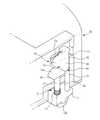
셔터부(50)는 도2,3에 도시된 바와 같이 상부에 회전축(51)이 형성되며 흡입구(32)측에 회전 가능하게 고정되는 개폐판(52)과, 개폐판(52)을 회전시키는 외력을 가하기 용이하도록 회전축(51)으로부터 연장 형성된 레버부(53)와, 외력이 작용하지 아니하는 경우 개폐판(52)이 흡입구(32)를 폐쇄한 상태를 유지시키도록 탄성력을 제공하는 탄성부재(54)를 포함하여 이루어진다.As shown in FIGS. 2 and 3, the
개폐판(52)은 흡입구(32)에 대응하여 대략 직사각형 형상의 판재로 마련된다. 개폐판(52)의 상부에는 회전축(51)이 형성되어 개폐판(52)은 흡입구(32)의 상측에 회전 가능하게 고정된다.The opening and closing
레버부(53)는 회전축(51)과 결합하여 먼지통(30)의 양측면으로부터 돌출 형성된다. 개폐판(52)은 레버부(53)의 A-B방향의 회전에 따라 흡입구(32)를 개방하거나 폐쇄하도록 회전한다.The
이때 레버부(53)에 대응하는 본체(10)의 먼지통설치부(17)에는 레버부(53)의 회전을 가이드하는 가이드부(17a)가 형성된다.At this time, a
이때 레버부(53)는 먼지통(30)의 어느 한 측면에만 형성될 수 있으며, 이에 대응하여 먼지통설치부에도 단일의 가이드부가 형성될 수 있다. 단일의 레버부를 형성하는 경우에도 본 발명의 바람직한 실시예와 동일하게 개폐판을 회전시킬 수 있음은 물론이다.In this case, the
따라서 먼지통(30)이 먼지통설치부(17)에 결합된 상태에서도 가이드부(17a)가 레버부(53)의 회전공간을 제공함으로써 레버부(53)를 회전시켜 개폐판(52)이 흡 입구(32)를 개폐하게 할 수 있다.Therefore, even when the
탄성부재(54)는 레버부(53)에 외력이 작동하지 아니하는 경우 개폐판(52)이 흡입구(32)를 닫은 상태를 유지하도록 탄성력을 제공하기 위해 회전축(51)에 결합된다.The
탄성부재(54)의 중앙부는 회전축(51)에 삽입되고 일단은 먼지통(30)의 외측면에 고정되며, 타단은 레버부(53)에 고정된다.The central portion of the
따라서 레버부(53)에 외력을 가하여 레버부(53)를 회전시키면 탄성부재(54)가 변형되면서 개폐판(52)이 흡입구(32)를 개방하고, 외력을 제거하면 탄성부재(54)의 복원력에 의해 레버부(53)가 원상태로 복원된다. 이때 개폐판(52)은 레버부(53)의 회전에 따라 회전하여 흡입구(32)를 폐쇄하게 된다.Accordingly, when the
스토퍼부(60)는 레버부(53)에 대응하여 본체(10)의 먼지통설치부(17)의 양측면 외측에 한쌍으로 마련된다.The
스토퍼부(60)는 먼지통설치부(17)의 측면 외측에 형성된 회전축부(61)와, 회전축부(61)에 대해 회전 가능하게 결합되는 스토퍼부재(62)를 포함하여 이루어진다.The
스토퍼부재(62)의 후면은 먼지통(30) 삽입시 레버부(53)가 접하는 레버접촉부(63)가 직선형으로 형성되며, 레버접촉부(63)의 상단은 레버부(53)의 이탈을 방지하도록 곡선형으로 형성된다.The rear surface of the
또한 레버접촉부(63)의 반대면에는 후술할 스토퍼지지부(74)가 안착될 수 있도록 안착부(64)가 형성된다.In addition, a mounting
이때, 스토퍼지지부(74)가 안착부(64)에 접하는 경우 스토퍼부(60)의 회동이 제한되어 먼지통(30) 삽입시 레버부(53)가 스토퍼부재(62)의 레버접촉부(63)에 의해 가압되어 레버부(53)가 회동하여 개폐판(52)이 흡입구(32)를 개방시킨다.At this time, when the
따라서 본체(10)와 분리된 먼지통(30)의 흡입구(32)는 폐쇄된 상태를 유지하고, 본체(10)와 먼지통(30)을 결합하면 흡입구(32)를 폐쇄하는 개폐판(52)이 회전하여 흡입구(32)를 개방하게 된다. 즉, 먼지통(30)의 착탈과 연동하여 먼지통(30)의 흡입구(32)가 개폐된다.Therefore, the
스토퍼지지부(74)가 하향 이동하여 스토퍼지지부(74)가 안착부(64)에서 이격되는 경우 스토퍼부재(62)는 스토퍼지지부(74) 방향으로 회전하기 때문에 레버부(53)는 탄성부재(54)의 복원력에 의해 가이드부(17a)를 따라 회전하고 이와 연동하여 개폐판(52)이 흡입구(32)를 폐쇄한다. 즉, 스토퍼지지부(74)가 하향 이동하면 먼지통(30)이 먼지통설치부(17)에 장착된 상태에서도 먼지통(30)의 흡입구(32)를 폐쇄할 수 있게 된다.When the
이와 같이 스토퍼지지부(74)를 하향 이동시키는 일 예로 사용자가 본체(10)를 들어 올리는 경우 스토퍼지지부(74)가 하향으로 이동하게 할 수 있다.As such, as an example of moving the
본체(10)를 들어 올리는 경우 스토퍼지지부(74)가 하향 이동하는 구성은 다양한 기구적 수단으로 구형될 수 있지만 본 발명의 바람직한 실시예에서는 후방보조바퀴(12b)의 상하운동과 연동하여 스토퍼지지부(74)를 상하 이동하게 한다. In the case of lifting the
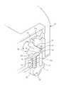
후방보조바퀴유닛(70)은 도 4에 도시된 바와 같이 후방보조바퀴(12b)와, 후방보조바퀴(12b)를 회전 가능하게 고정하기 위한 바퀴고정부(71)와, 바퀴고정 부(71)의 상부에 마련되어 보조바퀴(12b)의 상하운동을 가이드하는 제1,2가이드로드(72,73)와, 제1가이드로드(72)에 마련되어 본체(10) 하면과 바퀴고정부(71) 상면사이에 탄성력을 발생시키는 스프링(75)과, 제1가이드로드(72)의 상단에 형성된 스토퍼지지부(74)를 포함한다.As shown in FIG. 4, the rear
바퀴고정부(71)는 대략 원통형으로 형성되며, 내부에 보조바퀴(12b)가 회전 가능하게 장착되고, 본체(10)의 하면에 형성된 바퀴장착부(12c)에 바퀴고정부(71)가 안착된다.The
바퀴고정부(71)의 상부에는 가이드로드(72,73)가 형성되는데, 단일의 가이드로드를 이용하여 보조바퀴부의 상하운동을 가이드할 수 있으나, 바람직하게는 한 쌍의 가이드로드(72,73)를 이용함으로써 안정적으로 후방보조바퀴(12b)의 상하운동을 가이드할 수 있다.
스토퍼지지부(74)는 제1가이드로드(72)의 상단에 형성되어 보조바퀴(12b)의 상하운동에 따라 상하 이동한다.The
스토퍼지지부(74)의 상면은 스토퍼부재(62)의 원활한 회전을 위해 스토퍼부재(62)의 안착부(64)의 곡면형상에 대응하도록 곡면부(74a)가 형성된다.The upper surface of the
스프링(75)은 바퀴장착부(12c)의 하면과 바퀴고정부(71)의 상면사이에서 제1가이드로드(72)에 삽입되는데, 보조바퀴(12b)에 작용하는 본체(10)의 하중에 따라 탄성변형 가능하게 마련된 것으로 로봇청소기의 본체(10)가 외력이 가해지지 아니하는 상태에서 평평한 바닥에 놓여진 경우 본체(10)의 무게에 의해 스프링(75)이 수축된다.The
이때 후방보조바퀴(12b)가 바퀴장착부(12c)에 삽입된 상태를 유지하여 스토퍼지지부(74)가 스토퍼부재(62)를 상향 지지함으로써 스토퍼부재(62)가 레버부(53)를 가압하여 먼지통(30)의 흡입구(32)가 개방된다.At this time, the rear
사용자가 본체(10)를 들거나 외력에 의해 본체(10)가 들어 올려지는 경우 복원력에 의해 스프링(75)이 인장된다.When the user lifts the
이때, 후방보조바퀴(12b)가 하향으로 이동하면서 이와 일체로 형성된 스토퍼지지부(74) 역시 하향 이동하게 된다.At this time, as the rear
이와 같이 스토퍼지지부(74)가 하향 이동하게 되면 스토퍼부재(62)의 지지가 해제되어 스토퍼부재(62)는 스토퍼지지부(74) 방향으로 회전하게 된다.In this way, when the
결국 레버부(53)를 가압하는 스토퍼부재(62)가 회전함으로써 레버부(53)는 탄성 복원하여 개폐판(52)이 흡입구(32)를 폐쇄하는 위치로 회전한다.As a result, the
본체(10)와 먼지통(30)이 결합된 경우 사용자 등이 본체(10)를 들어 올리거나, 외력에 의해 본체(10)가 들어 올려지게 되면 후방보조바퀴유닛(70)의 스프링(75)이 인장되어 스토퍼부(60)를 지지하는 스토퍼지지부(74)가 하향 이동하게 되고, 스토퍼부(60)는 자중에 의해 스토퍼지지부(74)측으로 회전한다.When the
따라서 스토퍼부재(62)에 의해 가압된 상태를 유지하고 있는 레버부(53)는 가압상태가 해제됨으로써 셔터부(50)의 탄성부재(54)의 복원력에 의해 개폐판(52)이 흡입구(32)를 폐쇄하는 초기상태로 돌아가게 된다.Therefore, the
본 발명의 바람직한 실시예는 청소동작을 진행하는 동안 흡입구(32)를 개방하여 먼지 등을 포집부(31)내로 유입시킬 수 있으며, 먼지통(30)을 분리하는 경우, 또는 사용자 등이 본체를 들어 올리는 경우, 또는 단턱 등 외부적 요인에 의해 본체가 들어 올려지는 경우 먼지통(30)의 흡입구(32)가 폐쇄되기 때문에 먼지통(30)에 포집된 먼지 등이 외부로 역류하는 것을 방지할 수 있다.According to a preferred embodiment of the present invention, while the cleaning operation is performed, the
이러한 구성은 비록 도면에 개시하지 아니하였지만 먼지통이 본체로부터 착탈 가능하지 아니한 로봇청소기에 동일하게 적용할 수 있음은 물론이다.Although this configuration is not disclosed in the drawings, it is a matter of course that the dust container is equally applicable to the robot cleaner which is not detachable from the main body.
먼지통이 분리되지 않도록 본체내에 내장된 로봇청소기의 경우에도 사용자 등이 본체를 들어 올리는 경우, 또는 단턱 등 외부적 요인에 의해 본체가 들어 올려지는 경우 먼지통의 흡입구를 폐쇄시켜 먼지통에 포집된 먼지 등이 외부로 역류하는 것을 방지할 수 있다.Even when the robot cleaner is built in the main body to prevent the dust box from being separated, when the user lifts the main body or the main body is lifted by an external factor such as a step, the dust inlet is closed by closing the inlet of the dust box. Reverse flow to the outside can be prevented.
다음은 본 발명에 따른 로봇청소기의 동작을 설명하기로 한다.Next will be described the operation of the robot vacuum cleaner according to the present invention.
도 4내지 7은 본 발명의 바람직한 실시예에 따른 로봇청소기의 동작을 나타내는 도면이다.4 to 7 is a view showing the operation of the robot cleaner according to a preferred embodiment of the present invention.
먼저, 먼지통(30)이 분리된 상태에서는 탄성부재(54)의 탄성력에 의해 개폐판(52)이 흡입구(32)를 폐쇄하는 상태를 유지한다.First, in the state in which the
로봇청소기의 본체(10)가 바닥에 놓여진 상태에서 즉, 본체(10)의 하중에 의해 후방보조바퀴유닛(70)의 스프링(75)이 수축된 상태에서 먼지통(30)을 본체(10)에 결합시키면 먼지통(30) 삽입시 레버부(53)가 스토퍼부재(62)의 레버접촉부(63)에 의해 가압되어 레버부(53)가 도 5의 B방향으로 회동하여 개폐판(52)이 흡입구(32)를 개방시킨다.The
이와 반대로 먼지통(30)을 본체(10)에서 분리시키면 탄성부재(54)의 탄성력 에 의해 개폐판(52)이 회전하여 흡입구(32)를 폐쇄하게 된다.On the contrary, when the
따라서 먼지통(30)의 분리시 먼지통(30)내의 먼지 등이 외부로 역류하는 것을 방지할 수 있다.Therefore, when the
또한, 먼지통(30)이 결합된 상태에서 본체(10)를 들어 올리거나, 단턱 등에 의해 본체(10)가 들어 올려지면 도 6에 도시된 바와 같이 후방보조바퀴유닛(70)에 작용하는 하중이 작아지게 되어 후방보조바퀴유닛(70)의 스프링(75)이 인장되면서 후방보조바퀴(12b)가 하향 운동하게 된다.In addition, when the
이와 동시에 제1가이드로드(72)의 상부에 마련되어 스토퍼부재(62)의 회전을 제한하고 있는 스토퍼지지부(74)가 하향 이동하여 스토퍼부재(62)가 도6의 C방향으로 회전하게 된다.At the same time, the
따라서 레버부(53)를 가압하고 있는 스토퍼부재(62)가 회전하여 레버부(53)의 가압력이 해제되기 때문에 레버부(53)는 탄성부재(54)의 복원력에 의해 도7의 A방향으로 회전하게 되어 개폐판(52)이 흡입구(32)를 폐쇄하게 된다.Accordingly, since the
따라서 사용자가 본체(10)를 들거나, 기타 요인으로 인하여 본체(10)가 들려지게 되어 먼지 등이 배출될 수 있는 상황이 발생하는 경우에 개폐판(52)이 흡입구(32)를 폐쇄하기 때문에 흡입구(32)를 통해 포집부(31)내의 먼지 등이 외부로 역류하는 것을 방지할 수 있는 효과가 있다.Therefore, when the user lifts the
또한, 본체가 들려진 상태에서 다시 바닥에 놓여져 후방보조바퀴(12b)에 큰 하중이 작용하게 되는 경우 도4와 같이 후방보조바퀴유닛(70)의 스프링이 수축되면서 후방보조바퀴(12b)가 상향 이동하고, 이와 동시에 스토퍼지지부(74)가 상향 이 동하게 된다.In addition, when the main body is lifted up again on the floor and a large load acts on the
따라서 스토퍼지지부(74)가 스토퍼부재(62)를 D방향으로 밀어 올리게 되는데, 이와 같은 동작으로 인하여 스토퍼부재(62)가 레버부(53)를 도 5의 B방향으로 회전시켜 개폐판(52)이 흡입구(32)를 개방하게 된다.Accordingly, the
상기의 설명에서와 같이, 본 발명에 의한 로봇청소기는 역류방지장치를 구비하여 먼지통내의 먼지 등이 외부로 유출될 가능성이 있는 상황에서 먼지통내에 포집된 먼지가 쏟아지는 것을 방지할 수 있는 효과가 있다.As described above, the robot cleaner according to the present invention is provided with a backflow prevention device to prevent the dust collected in the dust container from being spilled in a situation that dust in the dust container may leak to the outside.
Claims (12)
Translated fromKoreanPriority Applications (4)
| Application Number | Priority Date | Filing Date | Title |
|---|---|---|---|
| KR1020070104300AKR101330735B1 (en) | 2007-10-17 | 2007-10-17 | Robot cleaner |
| EP08161740.9AEP2050380B1 (en) | 2007-10-17 | 2008-08-04 | Robot cleaner |
| US12/222,301US8065778B2 (en) | 2007-10-17 | 2008-08-06 | Robot cleaner |
| US13/292,471US8341802B2 (en) | 2007-10-17 | 2011-11-09 | Robot cleaner |
Applications Claiming Priority (1)
| Application Number | Priority Date | Filing Date | Title |
|---|---|---|---|
| KR1020070104300AKR101330735B1 (en) | 2007-10-17 | 2007-10-17 | Robot cleaner |
Publications (2)
| Publication Number | Publication Date |
|---|---|
| KR20090038965A KR20090038965A (en) | 2009-04-22 |
| KR101330735B1true KR101330735B1 (en) | 2013-11-20 |
Family
ID=40251672
Family Applications (1)
| Application Number | Title | Priority Date | Filing Date |
|---|---|---|---|
| KR1020070104300AExpired - Fee RelatedKR101330735B1 (en) | 2007-10-17 | 2007-10-17 | Robot cleaner |
Country Status (3)
| Country | Link |
|---|---|
| US (2) | US8065778B2 (en) |
| EP (1) | EP2050380B1 (en) |
| KR (1) | KR101330735B1 (en) |
Cited By (15)
| Publication number | Priority date | Publication date | Assignee | Title |
|---|---|---|---|---|
| CN106580187A (en)* | 2015-10-16 | 2017-04-26 | 日立空调·家用电器株式会社 | Autonomous traveling type vacuum cleaner |
| WO2017200343A1 (en)* | 2016-05-20 | 2017-11-23 | 엘지전자 주식회사 | Robot cleaner |
| US10342405B2 (en) | 2016-05-20 | 2019-07-09 | Lg Electronics Inc. | Autonomous cleaner |
| US10362916B2 (en) | 2016-05-20 | 2019-07-30 | Lg Electronics Inc. | Autonomous cleaner |
| US10398276B2 (en) | 2016-05-20 | 2019-09-03 | Lg Electronics Inc. | Autonomous cleaner |
| US10420448B2 (en) | 2016-05-20 | 2019-09-24 | Lg Electronics Inc. | Autonomous cleaner |
| US10441128B2 (en) | 2016-05-20 | 2019-10-15 | Lg Electronics Inc. | Autonomous cleaner |
| US10463212B2 (en) | 2016-05-20 | 2019-11-05 | Lg Electronics Inc. | Autonomous cleaner |
| US10463221B2 (en) | 2016-05-20 | 2019-11-05 | Lg Electronics Inc. | Autonomous cleaner |
| US10481611B2 (en) | 2016-05-20 | 2019-11-19 | Lg Electronics Inc. | Autonomous cleaner |
| US10524628B2 (en) | 2016-05-20 | 2020-01-07 | Lg Electronics Inc. | Autonomous cleaner |
| KR20200001749U (en)* | 2019-01-28 | 2020-08-05 | 쟈싱 아이클린 스마트 하우스홀드 캄파니, 리미티드 | Floor sweeper |
| KR102190776B1 (en)* | 2019-06-21 | 2020-12-14 | 주식회사 에이아이브릿지 | Elastic wave detector for bridge and, cavity exploring system including the same |
| KR102246264B1 (en)* | 2019-11-20 | 2021-04-29 | 주식회사 애니텍 | Dust collector which works in conjunction with air conditioner of train |
| US11846937B2 (en) | 2016-05-20 | 2023-12-19 | Lg Electronics Inc. | Autonomous cleaner |
Families Citing this family (92)
| Publication number | Priority date | Publication date | Assignee | Title |
|---|---|---|---|---|
| US8973196B2 (en)* | 2008-12-08 | 2015-03-10 | Emerson Electric Co. | Slide-out drum with filter for a wet/dry vacuum appliance |
| US9572465B2 (en) | 2008-12-08 | 2017-02-21 | Emerson Electric Co. | Slide out drum with filter for a wet/dry vacuum appliance |
| KR20100132891A (en)* | 2009-06-10 | 2010-12-20 | 삼성광주전자 주식회사 | Cleaning device and dust collection method using the same |
| US8438694B2 (en)* | 2009-06-19 | 2013-05-14 | Samsung Electronics Co., Ltd. | Cleaning apparatus |
| EP2316322A3 (en)* | 2009-11-02 | 2011-06-29 | LG Electronics Inc. | Robot cleaner |
| TW201127506A (en)* | 2010-02-11 | 2011-08-16 | cheng-xiang Yan | Thin type automatic cleaning device |
| KR101496913B1 (en)* | 2010-11-03 | 2015-03-02 | 삼성전자 주식회사 | Robot cleaner, automatic exhaust station and robot cleaner system having the same |
| TWM407724U (en)* | 2011-01-14 | 2011-07-21 | Micro Star Internat Corp Ltd | Dust collecting box and vacuum cleaner applying the same |
| GB2494446B (en)* | 2011-09-09 | 2013-12-18 | Dyson Technology Ltd | Autonomous cleaning appliance |
| GB2494443B (en)* | 2011-09-09 | 2013-08-07 | Dyson Technology Ltd | Autonomous surface treating appliance |
| GB2494447B (en)* | 2011-09-09 | 2014-02-26 | Dyson Technology Ltd | Autonomous surface treating appliance |
| KR101352287B1 (en)* | 2012-03-08 | 2014-01-17 | 엘지전자 주식회사 | Nozzle cover and robot cleaner comprising the same |
| ES2610755T3 (en) | 2012-08-27 | 2017-05-03 | Aktiebolaget Electrolux | Robot positioning system |
| US9326654B2 (en)* | 2013-03-15 | 2016-05-03 | Irobot Corporation | Roller brush for surface cleaning robots |
| KR102137923B1 (en) | 2013-04-15 | 2020-07-24 | 에이비 엘렉트로룩스 | Robotic vacuum cleaner with protruding sidebrush |
| WO2014169943A1 (en) | 2013-04-15 | 2014-10-23 | Aktiebolaget Electrolux | Robotic vacuum cleaner |
| JP6349072B2 (en)* | 2013-11-11 | 2018-06-27 | シャープ株式会社 | Self-propelled vacuum cleaner |
| JP6289054B2 (en)* | 2013-11-25 | 2018-03-07 | シャープ株式会社 | Self-propelled vacuum cleaner |
| CN105793790B (en) | 2013-12-19 | 2022-03-04 | 伊莱克斯公司 | Prioritize cleaning areas |
| KR102116596B1 (en) | 2013-12-19 | 2020-05-28 | 에이비 엘렉트로룩스 | Robotic vacuum cleaner with side brush moving in spiral pattern |
| CN105829985B (en) | 2013-12-19 | 2020-04-07 | 伊莱克斯公司 | Robot cleaning device with peripheral recording function |
| US10433697B2 (en) | 2013-12-19 | 2019-10-08 | Aktiebolaget Electrolux | Adaptive speed control of rotating side brush |
| US10617271B2 (en) | 2013-12-19 | 2020-04-14 | Aktiebolaget Electrolux | Robotic cleaning device and method for landmark recognition |
| WO2015090405A1 (en) | 2013-12-19 | 2015-06-25 | Aktiebolaget Electrolux | Sensing climb of obstacle of a robotic cleaning device |
| US10209080B2 (en) | 2013-12-19 | 2019-02-19 | Aktiebolaget Electrolux | Robotic cleaning device |
| CN105813527A (en)* | 2013-12-20 | 2016-07-27 | 伊莱克斯公司 | Autonomous cleaner |
| WO2015090439A1 (en) | 2013-12-20 | 2015-06-25 | Aktiebolaget Electrolux | Dust container |
| KR101573192B1 (en)* | 2014-05-30 | 2015-12-01 | 주식회사 유진로봇 | Cleaning robot having improved driving and cleaning ability |
| CN106415423B (en) | 2014-07-10 | 2021-01-01 | 伊莱克斯公司 | Method for detecting a measurement error of a robotic cleaning device |
| EP3190938A1 (en) | 2014-09-08 | 2017-07-19 | Aktiebolaget Electrolux | Robotic vacuum cleaner |
| US10499778B2 (en) | 2014-09-08 | 2019-12-10 | Aktiebolaget Electrolux | Robotic vacuum cleaner |
| EP3230814B1 (en) | 2014-12-10 | 2021-02-17 | Aktiebolaget Electrolux | Using laser sensor for floor type detection |
| CN107072454A (en) | 2014-12-12 | 2017-08-18 | 伊莱克斯公司 | Side brushes and robot vacuums |
| EP3234713B1 (en) | 2014-12-16 | 2022-06-15 | Aktiebolaget Electrolux | Cleaning method for a robotic cleaning device |
| CN107003669B (en) | 2014-12-16 | 2023-01-31 | 伊莱克斯公司 | Experience-Based Roadmap for Robotic Cleaning Equipment |
| US9885196B2 (en) | 2015-01-26 | 2018-02-06 | Hayward Industries, Inc. | Pool cleaner power coupling |
| US9909333B2 (en) | 2015-01-26 | 2018-03-06 | Hayward Industries, Inc. | Swimming pool cleaner with hydrocyclonic particle separator and/or six-roller drive system |
| JP5894692B2 (en)* | 2015-04-15 | 2016-03-30 | シャープ株式会社 | Self-propelled vacuum cleaner |
| US11099554B2 (en) | 2015-04-17 | 2021-08-24 | Aktiebolaget Electrolux | Robotic cleaning device and a method of controlling the robotic cleaning device |
| EP3344104B1 (en) | 2015-09-03 | 2020-12-30 | Aktiebolaget Electrolux | System of robotic cleaning devices |
| JP6546863B2 (en)* | 2016-02-17 | 2019-07-17 | 日立グローバルライフソリューションズ株式会社 | Electric vacuum cleaner |
| WO2017157421A1 (en) | 2016-03-15 | 2017-09-21 | Aktiebolaget Electrolux | Robotic cleaning device and a method at the robotic cleaning device of performing cliff detection |
| US11122953B2 (en) | 2016-05-11 | 2021-09-21 | Aktiebolaget Electrolux | Robotic cleaning device |
| CN107913034B (en)* | 2016-10-06 | 2021-05-14 | 日立环球生活方案株式会社 | electric vacuum cleaner |
| JP6917692B2 (en)* | 2016-10-06 | 2021-08-11 | 日立グローバルライフソリューションズ株式会社 | Self-propelled vacuum cleaner, dust sensor unit and dust case |
| JP2018061533A (en)* | 2016-10-11 | 2018-04-19 | 日立アプライアンス株式会社 | Vacuum cleaner |
| JP7063534B2 (en)* | 2016-10-13 | 2022-05-09 | 日立グローバルライフソリューションズ株式会社 | Self-propelled electric vacuum cleaner |
| KR102683646B1 (en)* | 2016-10-19 | 2024-07-11 | 삼성전자주식회사 | Robot cleaner |
| WO2018074848A1 (en) | 2016-10-19 | 2018-04-26 | Samsung Electronics Co., Ltd. | Robot vacuum cleaner |
| US9885194B1 (en) | 2017-05-11 | 2018-02-06 | Hayward Industries, Inc. | Pool cleaner impeller subassembly |
| US9878739B1 (en) | 2017-05-11 | 2018-01-30 | Hayward Industries, Inc. | Pool cleaner modular drivetrain |
| US10156083B2 (en) | 2017-05-11 | 2018-12-18 | Hayward Industries, Inc. | Pool cleaner power coupling |
| US9896858B1 (en) | 2017-05-11 | 2018-02-20 | Hayward Industries, Inc. | Hydrocyclonic pool cleaner |
| CN107115068B (en)* | 2017-05-30 | 2024-02-13 | 扬州金威环保科技有限公司 | A cleaning and dust return system for floor washing machines |
| EP3629869B1 (en) | 2017-06-02 | 2023-08-16 | Aktiebolaget Electrolux | Method of detecting a difference in level of a surface in front of a robotic cleaning device |
| JP2020533028A (en)* | 2017-09-11 | 2020-11-19 | シャークニンジャ オペレーティング エルエルシー | Cleaning device |
| US11426038B2 (en)* | 2017-09-11 | 2022-08-30 | Sharkninja Operating Llc | Cleaning device |
| EP3687357B1 (en) | 2017-09-26 | 2024-07-10 | Aktiebolaget Electrolux | Controlling movement of a robotic cleaning device |
| US12426753B2 (en) | 2017-11-16 | 2025-09-30 | Irobot Corporation | Washable bin for a robot vacuum cleaner |
| US11219347B2 (en) | 2017-12-22 | 2022-01-11 | Bissell Inc. | Robotic cleaner |
| KR102024088B1 (en)* | 2018-02-05 | 2019-11-04 | 엘지전자 주식회사 | A cleaner |
| CN108042050A (en)* | 2018-02-09 | 2018-05-18 | 长沙梅翎电子科技有限公司 | Sweeping robot |
| CN112004449B (en) | 2018-05-01 | 2021-05-25 | 尚科宁家运营有限公司 | Docking station for robot cleaner |
| CN115089055B (en) | 2018-07-20 | 2024-02-13 | 尚科宁家运营有限公司 | Docking station and cleaning system for robotic cleaner |
| TWI693055B (en)* | 2018-09-12 | 2020-05-11 | 聯潤科技股份有限公司 | Cleaning method, device and cleaning system |
| CN210931172U (en)* | 2019-06-17 | 2020-07-07 | 江苏美的清洁电器股份有限公司 | Self-moving cleaning device |
| CA3118015A1 (en) | 2018-11-01 | 2020-05-07 | Sharkninja Operating Llc | Cleaning device |
| US11426044B1 (en) | 2018-12-18 | 2022-08-30 | Sharkninja Operating Llc | Cleaning device |
| CN215605351U (en) | 2018-12-18 | 2022-01-25 | 尚科宁家运营有限公司 | Cleaning device replacement head |
| US11109727B2 (en) | 2019-02-28 | 2021-09-07 | Irobot Corporation | Cleaning rollers for cleaning robots |
| CN213665070U (en)* | 2019-03-11 | 2021-07-13 | 尚科宁家运营有限公司 | Robot cleaner and robot cleaning system |
| KR102245799B1 (en)* | 2019-03-19 | 2021-04-28 | 엘지전자 주식회사 | Air conditioner |
| KR102267826B1 (en)* | 2019-03-19 | 2021-06-23 | 엘지전자 주식회사 | Air conditioner |
| JP2020199263A (en)* | 2019-06-12 | 2020-12-17 | ビッセル インク. | Robotic cleaner |
| JP6795654B2 (en)* | 2019-06-21 | 2020-12-02 | 日立グローバルライフソリューションズ株式会社 | Vacuum cleaner |
| US11219345B2 (en) | 2019-10-31 | 2022-01-11 | Sharkninja Operating Llc | Replacement head for a vacuum |
| US11266283B2 (en) | 2019-10-31 | 2022-03-08 | Sharkninja Operating Llc | Replacement head for a vacuum |
| US11452414B2 (en) | 2019-10-31 | 2022-09-27 | Sharkninja Operating Llc | Replacement head for a vacuum |
| US10959584B1 (en) | 2019-10-31 | 2021-03-30 | Sharkninja Operating Llc | Replacement head for a vacuum |
| USD946223S1 (en) | 2020-02-14 | 2022-03-15 | Sharkninja Operating Llc | Cleaning device |
| USD946843S1 (en) | 2020-02-14 | 2022-03-22 | Sharkninja Operating Llc | Cleaning device |
| US11471019B2 (en) | 2020-02-14 | 2022-10-18 | Sharkninja Operating Llc | Cleaning device with lights |
| USD946842S1 (en) | 2020-02-14 | 2022-03-22 | Sharkninja Operating Llc | Cleaning device |
| USD946226S1 (en) | 2020-02-14 | 2022-03-15 | Sharkninja Operating Llc | Cleaning device |
| US10952580B1 (en) | 2020-02-19 | 2021-03-23 | Sharkninja Operating Llc | Cleaning device with rotatable head |
| US11179014B2 (en) | 2020-02-19 | 2021-11-23 | Sharkninja Operating Llc | Cleaning device system and method for use |
| CN111358376B (en)* | 2020-04-27 | 2025-08-22 | 湖南鹏耀科技有限公司 | A dust-preventing mechanism for a dust collecting box of a sweeping machine |
| CN111345740B (en)* | 2020-04-27 | 2025-08-29 | 湖南鹏耀科技有限公司 | Device for preventing dust from falling from dust box of sweeper |
| CN212630682U (en)* | 2020-04-30 | 2021-03-02 | 深圳市银星智能科技股份有限公司 | Storage box and cleaning robot |
| KR20220000297A (en)* | 2020-06-25 | 2022-01-03 | 삼성전자주식회사 | Docking station, mobile robot and mobile robot management system for controlling the docking station and the mobile robot |
| CN114680733A (en)* | 2020-12-29 | 2022-07-01 | 大连理工江苏研究院有限公司 | Adjustable floor sweeping robot |
| CN114903382B (en)* | 2022-06-02 | 2025-07-25 | 深圳市云视机器人有限公司 | Dust box, floor cleaning equipment and system |
Citations (4)
| Publication number | Priority date | Publication date | Assignee | Title |
|---|---|---|---|---|
| JPH0889451A (en)* | 1994-09-26 | 1996-04-09 | Nippon Yusoki Co Ltd | Self-mobile cleaner |
| JP2001046283A (en) | 1999-08-13 | 2001-02-20 | Kbm Tsusho:Kk | Nozzle head, and air circulating type vacuum cleaner equipped with the same |
| KR200335861Y1 (en) | 2003-09-05 | 2003-12-11 | 주식회사 마이크로로보트 | Backward flow Protector for dust Collector |
| JP2007130129A (en)* | 2005-11-09 | 2007-05-31 | Sanyo Electric Co Ltd | Self-propelled vacuum cleaner |
Family Cites Families (8)
| Publication number | Priority date | Publication date | Assignee | Title |
|---|---|---|---|---|
| US1143959A (en)* | 1911-12-09 | 1915-06-22 | Benjamin E Harris | Cleaning apparatus. |
| DE530392C (en)* | 1929-10-19 | 1931-07-28 | Aeg | vacuum cleaner |
| KR100485705B1 (en)* | 2003-02-21 | 2005-04-28 | 삼성광주전자 주식회사 | Dust collecting container for vacuum cleaner |
| AU2004202836B2 (en)* | 2003-07-24 | 2006-03-09 | Samsung Gwangju Electronics Co., Ltd. | Dust Receptacle of Robot Cleaner |
| US7329294B2 (en)* | 2003-10-23 | 2008-02-12 | Polar Light Limited | Dirt container for a surface cleaning apparatus and method of use |
| TWM294295U (en)* | 2005-12-27 | 2006-07-21 | Supply Internat Co Ltd E | Self-propelled device with fast detachable dust collecting box |
| KR20070074146A (en)* | 2006-01-06 | 2007-07-12 | 삼성전자주식회사 | Cleaner system |
| FR2896005B1 (en)* | 2006-01-11 | 2008-04-04 | Max Roumagnac | POOL CLEANER ROBOT |
- 2007
- 2007-10-17KRKR1020070104300Apatent/KR101330735B1/ennot_activeExpired - Fee Related
- 2008
- 2008-08-04EPEP08161740.9Apatent/EP2050380B1/ennot_activeCeased
- 2008-08-06USUS12/222,301patent/US8065778B2/ennot_activeExpired - Fee Related
- 2011
- 2011-11-09USUS13/292,471patent/US8341802B2/ennot_activeExpired - Fee Related
Patent Citations (4)
| Publication number | Priority date | Publication date | Assignee | Title |
|---|---|---|---|---|
| JPH0889451A (en)* | 1994-09-26 | 1996-04-09 | Nippon Yusoki Co Ltd | Self-mobile cleaner |
| JP2001046283A (en) | 1999-08-13 | 2001-02-20 | Kbm Tsusho:Kk | Nozzle head, and air circulating type vacuum cleaner equipped with the same |
| KR200335861Y1 (en) | 2003-09-05 | 2003-12-11 | 주식회사 마이크로로보트 | Backward flow Protector for dust Collector |
| JP2007130129A (en)* | 2005-11-09 | 2007-05-31 | Sanyo Electric Co Ltd | Self-propelled vacuum cleaner |
Cited By (23)
| Publication number | Priority date | Publication date | Assignee | Title |
|---|---|---|---|---|
| CN106580187A (en)* | 2015-10-16 | 2017-04-26 | 日立空调·家用电器株式会社 | Autonomous traveling type vacuum cleaner |
| US10481611B2 (en) | 2016-05-20 | 2019-11-19 | Lg Electronics Inc. | Autonomous cleaner |
| US10827896B2 (en) | 2016-05-20 | 2020-11-10 | Lg Electronics Inc. | Autonomous cleaner |
| US10342400B2 (en) | 2016-05-20 | 2019-07-09 | Lg Electronics Inc. | Autonomous cleaner |
| US10362916B2 (en) | 2016-05-20 | 2019-07-30 | Lg Electronics Inc. | Autonomous cleaner |
| US10398276B2 (en) | 2016-05-20 | 2019-09-03 | Lg Electronics Inc. | Autonomous cleaner |
| US10420448B2 (en) | 2016-05-20 | 2019-09-24 | Lg Electronics Inc. | Autonomous cleaner |
| US10441128B2 (en) | 2016-05-20 | 2019-10-15 | Lg Electronics Inc. | Autonomous cleaner |
| US10463212B2 (en) | 2016-05-20 | 2019-11-05 | Lg Electronics Inc. | Autonomous cleaner |
| US10463221B2 (en) | 2016-05-20 | 2019-11-05 | Lg Electronics Inc. | Autonomous cleaner |
| US11547263B2 (en) | 2016-05-20 | 2023-01-10 | Lg Electronics Inc. | Autonomous cleaner |
| US10342405B2 (en) | 2016-05-20 | 2019-07-09 | Lg Electronics Inc. | Autonomous cleaner |
| US10524628B2 (en) | 2016-05-20 | 2020-01-07 | Lg Electronics Inc. | Autonomous cleaner |
| WO2017200343A1 (en)* | 2016-05-20 | 2017-11-23 | 엘지전자 주식회사 | Robot cleaner |
| US10827895B2 (en) | 2016-05-20 | 2020-11-10 | Lg Electronics Inc. | Autonomous cleaner |
| US10835095B2 (en) | 2016-05-20 | 2020-11-17 | Lg Electronics Inc. | Autonomous cleaner |
| US10856714B2 (en) | 2016-05-20 | 2020-12-08 | Lg Electronics Inc. | Autonomous cleaner |
| US11846937B2 (en) | 2016-05-20 | 2023-12-19 | Lg Electronics Inc. | Autonomous cleaner |
| US10939792B2 (en) | 2016-05-20 | 2021-03-09 | Lg Electronics Inc. | Autonomous cleaner |
| KR20200001749U (en)* | 2019-01-28 | 2020-08-05 | 쟈싱 아이클린 스마트 하우스홀드 캄파니, 리미티드 | Floor sweeper |
| KR200494295Y1 (en)* | 2019-01-28 | 2021-09-08 | 쟈싱 아이클린 스마트 하우스홀드 캄파니, 리미티드 | Floor sweeper |
| KR102190776B1 (en)* | 2019-06-21 | 2020-12-14 | 주식회사 에이아이브릿지 | Elastic wave detector for bridge and, cavity exploring system including the same |
| KR102246264B1 (en)* | 2019-11-20 | 2021-04-29 | 주식회사 애니텍 | Dust collector which works in conjunction with air conditioner of train |
Also Published As
| Publication number | Publication date |
|---|---|
| US20090100630A1 (en) | 2009-04-23 |
| EP2050380A3 (en) | 2014-01-22 |
| KR20090038965A (en) | 2009-04-22 |
| EP2050380B1 (en) | 2019-03-13 |
| EP2050380A2 (en) | 2009-04-22 |
| US8065778B2 (en) | 2011-11-29 |
| US20120054980A1 (en) | 2012-03-08 |
| US8341802B2 (en) | 2013-01-01 |
Similar Documents
| Publication | Publication Date | Title |
|---|---|---|
| KR101330735B1 (en) | Robot cleaner | |
| KR102730954B1 (en) | Robot cleaner, station and cleaning system | |
| KR101204440B1 (en) | Robot cleaner system having robot cleaner and docking station | |
| CN101657135B (en) | A vacuum cleaner nozzle, a roller as well as a vacuum cleaner | |
| KR20080087596A (en) | robotic vacuum | |
| AU2003259634B2 (en) | Robot Cleaner | |
| EP2380475B1 (en) | Robot cleaner with improved dust collector | |
| KR101496913B1 (en) | Robot cleaner, automatic exhaust station and robot cleaner system having the same | |
| TWI688363B (en) | Electric sweeping robot | |
| CN114521838A (en) | Mop plate loading and unloading mechanism and cleaning system | |
| KR101393492B1 (en) | Apparatus for opening and closing dust collector for use in vacuum cleaner | |
| CN111904323B (en) | Dust deposition base and cleaning equipment assembly with same | |
| KR20070102844A (en) | Robot cleaner system with robot cleaner and docking station | |
| KR101256103B1 (en) | Robot cleaner system | |
| CN209953473U (en) | Cleaning device and cleaning device assembly | |
| KR20090034493A (en) | robotic vacuum | |
| KR102406189B1 (en) | Cleaner system | |
| KR20060038797A (en) | robotic vacuum | |
| KR101292537B1 (en) | Robot cleaner | |
| KR101330729B1 (en) | Robot cleaner | |
| JP2002369780A (en) | Dust collecting device | |
| KR20070016420A (en) | Suction unit of vacuum cleaner | |
| JP4010771B2 (en) | Electric vacuum cleaner | |
| JP2003070697A (en) | Suction tool for floor |
Legal Events
| Date | Code | Title | Description |
|---|---|---|---|
| PA0109 | Patent application | St.27 status event code:A-0-1-A10-A12-nap-PA0109 | |
| PG1501 | Laying open of application | St.27 status event code:A-1-1-Q10-Q12-nap-PG1501 | |
| R17-X000 | Change to representative recorded | St.27 status event code:A-3-3-R10-R17-oth-X000 | |
| A201 | Request for examination | ||
| PA0201 | Request for examination | St.27 status event code:A-1-2-D10-D11-exm-PA0201 | |
| R17-X000 | Change to representative recorded | St.27 status event code:A-3-3-R10-R17-oth-X000 | |
| D13-X000 | Search requested | St.27 status event code:A-1-2-D10-D13-srh-X000 | |
| D14-X000 | Search report completed | St.27 status event code:A-1-2-D10-D14-srh-X000 | |
| R18-X000 | Changes to party contact information recorded | St.27 status event code:A-3-3-R10-R18-oth-X000 | |
| E902 | Notification of reason for refusal | ||
| PE0902 | Notice of grounds for rejection | St.27 status event code:A-1-2-D10-D21-exm-PE0902 | |
| P11-X000 | Amendment of application requested | St.27 status event code:A-2-2-P10-P11-nap-X000 | |
| P13-X000 | Application amended | St.27 status event code:A-2-2-P10-P13-nap-X000 | |
| E902 | Notification of reason for refusal | ||
| PE0902 | Notice of grounds for rejection | St.27 status event code:A-1-2-D10-D21-exm-PE0902 | |
| T11-X000 | Administrative time limit extension requested | St.27 status event code:U-3-3-T10-T11-oth-X000 | |
| P11-X000 | Amendment of application requested | St.27 status event code:A-2-2-P10-P11-nap-X000 | |
| P13-X000 | Application amended | St.27 status event code:A-2-2-P10-P13-nap-X000 | |
| E701 | Decision to grant or registration of patent right | ||
| PE0701 | Decision of registration | St.27 status event code:A-1-2-D10-D22-exm-PE0701 | |
| GRNT | Written decision to grant | ||
| PR0701 | Registration of establishment | St.27 status event code:A-2-4-F10-F11-exm-PR0701 | |
| PR1002 | Payment of registration fee | St.27 status event code:A-2-2-U10-U11-oth-PR1002 Fee payment year number:1 | |
| PG1601 | Publication of registration | St.27 status event code:A-4-4-Q10-Q13-nap-PG1601 | |
| FPAY | Annual fee payment | Payment date:20161028 Year of fee payment:4 | |
| PR1001 | Payment of annual fee | St.27 status event code:A-4-4-U10-U11-oth-PR1001 Fee payment year number:4 | |
| FPAY | Annual fee payment | Payment date:20171030 Year of fee payment:5 | |
| PR1001 | Payment of annual fee | St.27 status event code:A-4-4-U10-U11-oth-PR1001 Fee payment year number:5 | |
| FPAY | Annual fee payment | Payment date:20181030 Year of fee payment:6 | |
| PR1001 | Payment of annual fee | St.27 status event code:A-4-4-U10-U11-oth-PR1001 Fee payment year number:6 | |
| PR1001 | Payment of annual fee | St.27 status event code:A-4-4-U10-U11-oth-PR1001 Fee payment year number:7 | |
| PR1001 | Payment of annual fee | St.27 status event code:A-4-4-U10-U11-oth-PR1001 Fee payment year number:8 | |
| PR1001 | Payment of annual fee | St.27 status event code:A-4-4-U10-U11-oth-PR1001 Fee payment year number:9 | |
| PC1903 | Unpaid annual fee | St.27 status event code:A-4-4-U10-U13-oth-PC1903 Not in force date:20221113 Payment event data comment text:Termination Category : DEFAULT_OF_REGISTRATION_FEE | |
| PC1903 | Unpaid annual fee | St.27 status event code:N-4-6-H10-H13-oth-PC1903 Ip right cessation event data comment text:Termination Category : DEFAULT_OF_REGISTRATION_FEE Not in force date:20221113 | |
| P22-X000 | Classification modified | St.27 status event code:A-4-4-P10-P22-nap-X000 |