KR101330630B1 - Method and apparatus for encoding moving picture, method and apparatus for decoding moving picture, applying adaptively an optimal prediction mode - Google Patents
Method and apparatus for encoding moving picture, method and apparatus for decoding moving picture, applying adaptively an optimal prediction modeDownload PDFInfo
- Publication number
- KR101330630B1 KR101330630B1KR1020060049080AKR20060049080AKR101330630B1KR 101330630 B1KR101330630 B1KR 101330630B1KR 1020060049080 AKR1020060049080 AKR 1020060049080AKR 20060049080 AKR20060049080 AKR 20060049080AKR 101330630 B1KR101330630 B1KR 101330630B1
- Authority
- KR
- South Korea
- Prior art keywords
- color components
- image
- prediction mode
- prediction
- block
- Prior art date
- Legal status (The legal status is an assumption and is not a legal conclusion. Google has not performed a legal analysis and makes no representation as to the accuracy of the status listed.)
- Expired - Fee Related
Links
Images


Classifications
- H—ELECTRICITY
- H04—ELECTRIC COMMUNICATION TECHNIQUE
- H04N—PICTORIAL COMMUNICATION, e.g. TELEVISION
- H04N19/00—Methods or arrangements for coding, decoding, compressing or decompressing digital video signals
- H04N19/10—Methods or arrangements for coding, decoding, compressing or decompressing digital video signals using adaptive coding
- H04N19/102—Methods or arrangements for coding, decoding, compressing or decompressing digital video signals using adaptive coding characterised by the element, parameter or selection affected or controlled by the adaptive coding
- H04N19/103—Selection of coding mode or of prediction mode
- H—ELECTRICITY
- H04—ELECTRIC COMMUNICATION TECHNIQUE
- H04N—PICTORIAL COMMUNICATION, e.g. TELEVISION
- H04N19/00—Methods or arrangements for coding, decoding, compressing or decompressing digital video signals
- H04N19/10—Methods or arrangements for coding, decoding, compressing or decompressing digital video signals using adaptive coding
- H04N19/134—Methods or arrangements for coding, decoding, compressing or decompressing digital video signals using adaptive coding characterised by the element, parameter or criterion affecting or controlling the adaptive coding
- H04N19/136—Incoming video signal characteristics or properties
- G—PHYSICS
- G06—COMPUTING OR CALCULATING; COUNTING
- G06T—IMAGE DATA PROCESSING OR GENERATION, IN GENERAL
- G06T9/00—Image coding
- G06T9/007—Transform coding, e.g. discrete cosine transform
- H—ELECTRICITY
- H04—ELECTRIC COMMUNICATION TECHNIQUE
- H04N—PICTORIAL COMMUNICATION, e.g. TELEVISION
- H04N19/00—Methods or arrangements for coding, decoding, compressing or decompressing digital video signals
- H04N19/10—Methods or arrangements for coding, decoding, compressing or decompressing digital video signals using adaptive coding
- H04N19/102—Methods or arrangements for coding, decoding, compressing or decompressing digital video signals using adaptive coding characterised by the element, parameter or selection affected or controlled by the adaptive coding
- H04N19/103—Selection of coding mode or of prediction mode
- H04N19/109—Selection of coding mode or of prediction mode among a plurality of temporal predictive coding modes
- H—ELECTRICITY
- H04—ELECTRIC COMMUNICATION TECHNIQUE
- H04N—PICTORIAL COMMUNICATION, e.g. TELEVISION
- H04N19/00—Methods or arrangements for coding, decoding, compressing or decompressing digital video signals
- H04N19/10—Methods or arrangements for coding, decoding, compressing or decompressing digital video signals using adaptive coding
- H04N19/102—Methods or arrangements for coding, decoding, compressing or decompressing digital video signals using adaptive coding characterised by the element, parameter or selection affected or controlled by the adaptive coding
- H04N19/103—Selection of coding mode or of prediction mode
- H04N19/11—Selection of coding mode or of prediction mode among a plurality of spatial predictive coding modes
- H—ELECTRICITY
- H04—ELECTRIC COMMUNICATION TECHNIQUE
- H04N—PICTORIAL COMMUNICATION, e.g. TELEVISION
- H04N19/00—Methods or arrangements for coding, decoding, compressing or decompressing digital video signals
- H04N19/10—Methods or arrangements for coding, decoding, compressing or decompressing digital video signals using adaptive coding
- H04N19/134—Methods or arrangements for coding, decoding, compressing or decompressing digital video signals using adaptive coding characterised by the element, parameter or criterion affecting or controlling the adaptive coding
- H04N19/146—Data rate or code amount at the encoder output
- H04N19/147—Data rate or code amount at the encoder output according to rate distortion criteria
- H—ELECTRICITY
- H04—ELECTRIC COMMUNICATION TECHNIQUE
- H04N—PICTORIAL COMMUNICATION, e.g. TELEVISION
- H04N19/00—Methods or arrangements for coding, decoding, compressing or decompressing digital video signals
- H04N19/10—Methods or arrangements for coding, decoding, compressing or decompressing digital video signals using adaptive coding
- H04N19/134—Methods or arrangements for coding, decoding, compressing or decompressing digital video signals using adaptive coding characterised by the element, parameter or criterion affecting or controlling the adaptive coding
- H04N19/146—Data rate or code amount at the encoder output
- H04N19/15—Data rate or code amount at the encoder output by monitoring actual compressed data size at the memory before deciding storage at the transmission buffer
- H—ELECTRICITY
- H04—ELECTRIC COMMUNICATION TECHNIQUE
- H04N—PICTORIAL COMMUNICATION, e.g. TELEVISION
- H04N19/00—Methods or arrangements for coding, decoding, compressing or decompressing digital video signals
- H04N19/10—Methods or arrangements for coding, decoding, compressing or decompressing digital video signals using adaptive coding
- H04N19/169—Methods or arrangements for coding, decoding, compressing or decompressing digital video signals using adaptive coding characterised by the coding unit, i.e. the structural portion or semantic portion of the video signal being the object or the subject of the adaptive coding
- H04N19/17—Methods or arrangements for coding, decoding, compressing or decompressing digital video signals using adaptive coding characterised by the coding unit, i.e. the structural portion or semantic portion of the video signal being the object or the subject of the adaptive coding the unit being an image region, e.g. an object
- H04N19/176—Methods or arrangements for coding, decoding, compressing or decompressing digital video signals using adaptive coding characterised by the coding unit, i.e. the structural portion or semantic portion of the video signal being the object or the subject of the adaptive coding the unit being an image region, e.g. an object the region being a block, e.g. a macroblock
- H—ELECTRICITY
- H04—ELECTRIC COMMUNICATION TECHNIQUE
- H04N—PICTORIAL COMMUNICATION, e.g. TELEVISION
- H04N19/00—Methods or arrangements for coding, decoding, compressing or decompressing digital video signals
- H04N19/10—Methods or arrangements for coding, decoding, compressing or decompressing digital video signals using adaptive coding
- H04N19/169—Methods or arrangements for coding, decoding, compressing or decompressing digital video signals using adaptive coding characterised by the coding unit, i.e. the structural portion or semantic portion of the video signal being the object or the subject of the adaptive coding
- H04N19/186—Methods or arrangements for coding, decoding, compressing or decompressing digital video signals using adaptive coding characterised by the coding unit, i.e. the structural portion or semantic portion of the video signal being the object or the subject of the adaptive coding the unit being a colour or a chrominance component
- H—ELECTRICITY
- H04—ELECTRIC COMMUNICATION TECHNIQUE
- H04N—PICTORIAL COMMUNICATION, e.g. TELEVISION
- H04N19/00—Methods or arrangements for coding, decoding, compressing or decompressing digital video signals
- H04N19/10—Methods or arrangements for coding, decoding, compressing or decompressing digital video signals using adaptive coding
- H04N19/189—Methods or arrangements for coding, decoding, compressing or decompressing digital video signals using adaptive coding characterised by the adaptation method, adaptation tool or adaptation type used for the adaptive coding
- H04N19/19—Methods or arrangements for coding, decoding, compressing or decompressing digital video signals using adaptive coding characterised by the adaptation method, adaptation tool or adaptation type used for the adaptive coding using optimisation based on Lagrange multipliers
- H—ELECTRICITY
- H04—ELECTRIC COMMUNICATION TECHNIQUE
- H04N—PICTORIAL COMMUNICATION, e.g. TELEVISION
- H04N19/00—Methods or arrangements for coding, decoding, compressing or decompressing digital video signals
- H04N19/50—Methods or arrangements for coding, decoding, compressing or decompressing digital video signals using predictive coding
- H04N19/593—Methods or arrangements for coding, decoding, compressing or decompressing digital video signals using predictive coding involving spatial prediction techniques
- H—ELECTRICITY
- H04—ELECTRIC COMMUNICATION TECHNIQUE
- H04N—PICTORIAL COMMUNICATION, e.g. TELEVISION
- H04N19/00—Methods or arrangements for coding, decoding, compressing or decompressing digital video signals
- H04N19/60—Methods or arrangements for coding, decoding, compressing or decompressing digital video signals using transform coding
- H04N19/61—Methods or arrangements for coding, decoding, compressing or decompressing digital video signals using transform coding in combination with predictive coding
Landscapes
- Engineering & Computer Science (AREA)
- Multimedia (AREA)
- Signal Processing (AREA)
- Physics & Mathematics (AREA)
- General Physics & Mathematics (AREA)
- Discrete Mathematics (AREA)
- Theoretical Computer Science (AREA)
- Compression Or Coding Systems Of Tv Signals (AREA)
- Color Television Systems (AREA)
Abstract
Translated fromKorean
Description
Translated fromKorean도 1은 본 발명의 바람직한 일 실시예에 따른 동영상 부호화 장치의 구성도이다.1 is a block diagram of a video encoding apparatus according to an embodiment of the present invention.
도 2는 도 1에 도시된 레지듀 생성부(120)의 구성도이다.2 is a block diagram of the
도 3은 인터 예측에서의 매크로블록의 분할 방법을 도시한 도면이다.3 is a diagram illustrating a method of dividing a macroblock in inter prediction.
도 4는 인트라 예측에서의 예측 모습을 도시한 도면이다.4 is a diagram illustrating a prediction state in intra prediction.
도 5는 도 1에 도시된 레지듀 생성부(120)의 다른 구성도이다.5 is another configuration diagram of the
도 6은 도 1에 도시된 레지듀 생성부(120)의 또 다른 구성도이다.6 is another configuration diagram of the
도 7은 본 발명에 따른 바람직한 일 실시예에 적용되는 5-탭 필터와 3-탭 필터를 도시한 도면이다.7 is a diagram illustrating a 5-tap filter and a 3-tap filter applied to an exemplary embodiment of the present invention.
도 8은 도 1에 도시된 레지듀 생성부(120)의 또 다른 구성도이다.8 is another configuration diagram of the
도 9는 도 2에 도시된 복원 영상 생성부(180)의 구성도이다.9 is a configuration diagram of the reconstructed
도 10은 본 발명의 바람직한 일 실시예에 따른 동영상 복호화 장치의 구성도이다.10 is a block diagram of a video decoding apparatus according to an embodiment of the present invention.
도 11은 도 10에 도시된 예측 영상 생성부(240)의 구성도이다.FIG. 11 is a block diagram of the
도 12는 도 10에 도시된 복원 영상 생성부(250)의 구성도이다.12 is a configuration diagram of the reconstructed
도 13은 도 12에 도시된 레지듀 역변환부(251)의 구성도이다.FIG. 13 is a diagram illustrating the residue
도 14a-14b는 본 발명의 바람직한 일 실시예에 따른 동영상 부호화 방법의 흐름도이다.14A and 14B are flowcharts of a video encoding method, according to an embodiment of the present invention.
도 15는 본 발명의 바람직한 일 실시예에 따른 동영상 복호화 방법의 흐름도이다.15 is a flowchart of a video decoding method according to an embodiment of the present invention.
본 발명은 동영상을 부호화하는 방법 및 장치, 동영상을 복호화하는 방법 및 장치에 관한 것으로, 특히 H.264/MPEG-4 AVC(Advanced Video Coding) Fidelity Range Extensions(FRExt) 표준 분야에서의 동영상을 부호화하는 방법 및 장치, 동영상을 복호화하는 방법 및 장치에 관한 것이다.The present invention relates to a method and apparatus for encoding a video, a method and apparatus for decoding a video, and more particularly, to a video encoding in the field of H.264 / MPEG-4 Advanced Video Coding (AVC) Fidelity Range Extensions (FRExt) standard. A method and apparatus, and a method and apparatus for decoding a video.
"레지듀얼 색 변환(residual color transformation)"이라 불리는 새로운 RGB 부호화 기술은 H.264/MPEG-4 AVC Fidelity Range Extensions 표준화 과정에서 개발되었다. 이것은 RGB 색 공간을 YCbCr 색 공간으로 변환할 때 발생하는 화질 열화를 방지하기 위한 것이다. 그러나, H.264/MPEG-4 AVC FRExt 상의 RGB 부호화 및 복호화 기술도 동영상 재생 기기들에 적용하기에는 아직 동영상의 부호화 및 복호화 효율이 충분히 높지 않다는 문제점이 있었다.A new RGB encoding technique called "residual color transformation" was developed during the H.264 / MPEG-4 AVC Fidelity Range Extensions standardization process. This is to prevent image quality deterioration that occurs when converting the RGB color space to the YCbCr color space. However, RGB encoding and decoding techniques on H.264 / MPEG-4 AVC FRExt also have a problem in that encoding and decoding efficiency of video is not sufficiently high to be applied to video playback devices.
본 발명이 이루고자 하는 기술적 과제는 H.264/MPEG-4 AVC FRExt 상의 RGB 부호화 기술의 동영상 부호화 및 복호화 효율을 높일 수 있는 장치 및 방법을 제공하는데 있다. 또한, 상기된 방법을 컴퓨터에서 실행시키기 위한 프로그램을 기록한 컴퓨터로 읽을 수 있는 기록 매체를 제공하는데 있다.An object of the present invention is to provide an apparatus and method for improving video encoding and decoding efficiency of RGB encoding technology on H.264 / MPEG-4 AVC FRExt. It is another object of the present invention to provide a computer-readable recording medium storing a program for causing a computer to execute the above-described method.
상기 기술적 과제를 해결하기 위한 본 발명에 따른 부호화 장치에서의 예측 영상 생성 방법은 소정 영상의 특성에 기초하여 현재 영상의 색 성분들 각각의 블록 별로 상기 색 성분들 각각의 블록에 최적인 예측 모드를 선택하는 단계; 및 상기 선택된 예측 모드에 따라 상기 현재 영상에 대한 예측 영상을 생성하는 단계를 포함한다.According to an aspect of the present invention, there is provided a method of generating a predictive image in accordance with an embodiment of the present invention. The prediction mode is optimized for each block of each color component based on a characteristic of a predetermined image. Selecting; And generating a prediction image of the current image according to the selected prediction mode.
상기 다른 기술적 과제를 해결하기 위하여, 본 발명은 상기된 부호화 장치에서의 예측 영상 생성 방법을 컴퓨터에서 실행시키기 위한 프로그램을 기록한 컴퓨터로 읽을 수 있는 기록 매체를 제공한다.In order to solve the above other technical problem, the present invention provides a computer-readable recording medium having recorded thereon a program for executing a method of generating a predictive image in the above-described encoding apparatus on a computer.
상기 또 다른 기술적 과제를 해결하기 위한 본 발명에 따른 부호화 장치에서의 예측 영상 생성 장치는 소정 영상의 특성에 기초하여 현재 영상의 색 성분들 각각의 블록 별로 상기 색 성분들 각각의 블록에 최적인 예측 모드를 선택하는 선택부; 및 상기 선택된 예측 모드에 따라 상기 현재 영상에 대한 예측 영상을 생성하는 생성부를 포함한다.According to another aspect of the present invention, there is provided a prediction image generating apparatus in an encoding apparatus, which is optimal for each block of color components for each block of color components of a current image based on characteristics of a predetermined image. A selection unit for selecting a mode; And a generator configured to generate a predicted image of the current image according to the selected prediction mode.
상기 또 다른 기술적 과제를 해결하기 위한 본 발명에 따른 부호화 방법은 소정 영상의 특성에 기초하여 현재 영상의 색 성분들 각각의 블록 별로 상기 색 성분들 각각의 블록에 최적인 예측 모드를 선택하는 단계; 및 상기 선택된 예측 모드에 따라 상기 현재 영상에 대한 예측 영상을 생성하는 단계; 상기 현재 영상과 상기 예측 영상의 차이에 해당하는 색 성분들 각각의 레지듀를 생성하는 단계; 및 상기 생성된 레지듀들을 부호화함으로서 비트 스트림을 생성하는 단계를 포함한다.According to another aspect of the present invention, there is provided a coding method, comprising: selecting a prediction mode that is optimal for each block of each color component based on a characteristic of a predetermined image; Generating a prediction image for the current image according to the selected prediction mode; Generating residues of color components corresponding to a difference between the current image and the predicted image; And generating a bit stream by encoding the generated residues.
상기 또 다른 기술적 과제를 해결하기 위하여, 본 발명은 상기된 부호화 방법을 컴퓨터에서 실행시키기 위한 프로그램을 기록한 컴퓨터로 읽을 수 있는 기록 매체를 제공한다.In order to solve the above further technical problem, the present invention provides a computer-readable recording medium having recorded thereon a program for executing the above-described encoding method on a computer.
상기 또 다른 기술적 과제를 해결하기 위한 본 발명에 따른 부호화 장치는 소정 영상의 특성에 기초하여 현재 영상의 색 성분들 각각의 블록 별로 상기 색 성분들 각각의 블록에 최적인 예측 모드를 선택하는 선택부; 및 상기 선택된 예측 모드에 따라 상기 현재 영상에 대한 예측 영상을 생성하고, 상기 현재 영상과 상기 예측 영상의 차이에 해당하는 색 성분들 각각의 레지듀를 생성하는 생성부; 및 상기 생성된 레지듀들을 부호화함으로서 비트 스트림을 생성하는 부호화부를 포함한다.According to another aspect of the present invention, a coding apparatus according to the present invention selects a prediction mode that is optimal for each block of each of the color components based on a characteristic of a predetermined image. ; And a generator configured to generate a prediction image of the current image according to the selected prediction mode and to generate residues of color components corresponding to the difference between the current image and the prediction image. And an encoder configured to generate a bit stream by encoding the generated residues.
상기 또 다른 기술적 과제를 해결하기 위한 본 발명에 따른 복호화 장치에서의 예측 영상 생성 방법은 비트 스트림을 복호화함으로서 현재 영상의 색 성분들 각각의 블록에 최적인 예측 모드를 나타내는 정보를 복원하는 단계; 및 상기 복원된 정보가 나타내는 예측 모드에 따라 상기 현재 영상에 대한 예측 영상을 생성하는 단계를 포함한다.According to another aspect of the present invention, there is provided a method of generating a prediction image in a decoding apparatus, the method comprising: restoring information indicating a prediction mode optimal for each block of color components of a current image by decoding a bit stream; And generating a prediction image of the current image according to the prediction mode indicated by the restored information.
상기 또 다른 기술적 과제를 해결하기 위하여, 본 발명은 상기된 복호화 장치에서의 예측 영상 생성 방법을 컴퓨터에서 실행시키기 위한 프로그램을 기록한 컴퓨터로 읽을 수 있는 기록 매체를 제공한다.In order to solve the above technical problem, the present invention provides a computer-readable recording medium having recorded thereon a program for executing a method of generating a predictive image in the decoding apparatus.
상기 또 다른 기술적 과제를 해결하기 위한 본 발명에 따른 복호화 장치에서의 예측 영상 생성 장치는 비트 스트림을 복호화함으로서 현재 영상의 색 성분들 각각의 블록에 최적인 예측 모드를 나타내는 정보를 복원하는 복호화부; 및 상기 복원된 정보가 나타내는 예측 모드에 따라 상기 현재 영상에 대한 예측 영상을 생성하는 생성부를 포함한다.According to another aspect of the present invention, there is provided a prediction image generating apparatus in a decoding apparatus including: a decoding unit for reconstructing information representing a prediction mode optimal for each block of color components of a current image by decoding a bit stream; And a generator configured to generate a prediction image of the current image according to the prediction mode indicated by the reconstructed information.
상기 또 다른 기술적 과제를 해결하기 위한 본 발명에 따른 복호화 방법은 비트 스트림을 복호화함으로서 현재 영상의 색 성분들 각각의 블록에 최적인 예측 모드를 나타내는 정보를 복원하는 단계; 상기 복원된 정보가 나타내는 예측 모드에 따라 상기 현재 영상과 상기 현재 영상에 대한 예측 영상의 차이에 해당하는 레지듀들을 생성하는 단계; 상기 복원된 정보가 나타내는 예측 모드에 따라 상기 예측 영상을 생성하는 단계; 및 상기 생성된 레지듀들과 상기 생성된 예측 화면의 합산에 해당하는 복원 화면을 생성하는 단계를 포함한다.According to another aspect of the present invention, there is provided a decoding method comprising: restoring information indicating a prediction mode optimal for each block of color components of a current image by decoding a bit stream; Generating residues corresponding to a difference between the current image and the prediction image of the current image according to the prediction mode indicated by the reconstructed information; Generating the prediction image according to the prediction mode indicated by the restored information; And generating a reconstruction screen corresponding to the sum of the generated residues and the generated prediction screen.
상기 또 다른 기술적 과제를 해결하기 위하여, 본 발명은 상기된 복호화 방법을 컴퓨터에서 실행시키기 위한 프로그램을 기록한 컴퓨터로 읽을 수 있는 기록 매체를 제공한다.In order to solve the above further technical problem, the present invention provides a computer-readable recording medium having recorded thereon a program for executing the above-described decoding method on a computer.
상기 또 다른 기술적 과제를 해결하기 위한 본 발명에 따른 복호화 장치는 비트 스트림을 복호화함으로서 현재 영상의 색 성분들 각각의 블록에 최적인 예측 모드를 나타내는 정보를 복원하는 복호화부; 상기 복원된 정보가 나타내는 예측 모드에 따라 상기 예측 영상을 생성하는 제 1 생성부; 및 상기 복원된 정보가 나타내는 예측 모드에 따라 상기 현재 영상과 상기 현재 영상에 대한 예측 영상의 차이에 해당하는 레지듀들을 생성하고, 상기 생성된 레지듀들과 상기 생성된 예측 화면의 합산에 해당하는 복원 화면을 생성하는 제 2 생성부를 포함한다.According to another aspect of the present invention, there is provided a decoding apparatus comprising: a decoder configured to recover information indicating a prediction mode optimal for each block of color components of a current image by decoding a bit stream; A first generator configured to generate the prediction image according to the prediction mode indicated by the restored information; And generate residues corresponding to a difference between the current image and the prediction image of the current image according to the prediction mode indicated by the reconstructed information, and correspond to the sum of the generated residues and the generated prediction screen. And a second generator for generating a restoration screen.
이하에서는 도면을 참조하여 본 발명의 바람직한 실시예들을 상세히 설명한다. 특히, 이하의 실시예들에서 현재 영상은 현재 동영상 부호화 및 복호화의 대상이 되는 영상을 의미하고, 참조 영상은 현재 영상을 부호화하거나 복호화하는데 참조되는 영상을 의미한다. 일반적으로, 참조 영상은 현재 영상의 과거 영상이지만, 현재 영상의 미래 영상이 될 수 있으며, 복수의 영상들이 될 수도 있다.Hereinafter, preferred embodiments of the present invention will be described in detail with reference to the drawings. In particular, in the following embodiments, the current image refers to an image to be encoded and decoded, and the reference image refers to an image referenced to encode or decode the current image. In general, the reference image is a past image of the current image, but may be a future image of the current image and may be a plurality of images.
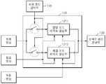
도 1은 본 발명의 바람직한 일 실시예에 따른 동영상 부호화 장치의 구성도이다.1 is a block diagram of a video encoding apparatus according to an embodiment of the present invention.
도 1을 참조하면, 본 실시예에 따른 동영상 부호화 장치는 최적 모드 선택부(110), 레지듀 생성부(120), 주파수 공간 변환부(130), 양자화부(400), 엔트로피 부호화부(150), 역양자화부(160), 주파수 공간 역변환부(170), 및 복원 영상 생성부(180)로 구성된다.Referring to FIG. 1, the video encoding apparatus according to the present embodiment may include an
최적 모드 선택부(110)는 샘플 영상의 특성에 기초하여 현재 영상의 색 성분들 각각의 매크로블록 별로 색 성분들 각각의 매크로블록에 최적인 예측 모드를 선택한다. 여기에서, 색 성분들 각각의 매크로블록은 서로 대응하는 매크로블록들이라는 것을 본 실시예가 속하는 기술 분야에서 통상의 지식을 가지 자라면 이해할 수 있다.The
예를 들면, 최적 모드 선택부(110)는 현재 영상의 색 성분들 각각의 매크로블록에 최적인 예측 모드로서 현재 영상의 색 성분들 각각의 매크로블록에 일률적(common)으로 적용되는 예측 모드(이하 "단일 예측 모드(sing prediction mode)"라 함) 및 현재 영상의 색 성분들 각각의 매크로블록에 독립적(independent)으로 적용되는 예측 모드(이하 "복합 예측 모드(multiple prediction mode)") 중 어느 하나를 선택할 수 있다.For example, the optimal
또한, 최적 모드 선택부(110)는 현재 영상의 색 성분들 각각의 매크로블록에 최적인 예측 모드로서 단일 예측 모드 및 복합 예측 모드 중 어느 하나를 선택하고, 이것들 중 단일 예측 모드를 선택한 경우에 색 성분들 각각의 제 1 레지듀간의 차이에 해당하는 제 2 레지듀들을 생성하는 예측 모드(이하 "레지듀 변환 모드"라 함)를 선택할 수도 있다.In addition, the optimal
또한, 최적 모드 선택부(110)는 현재 영상의 색 성분들 각각의 매크로블록에 최적인 예측 모드로서 단일 예측 모드 및 복합 예측 모드 중 어느 하나를 선택하고, 이것들 중 단일 예측 모드를 선택한 경우에 RCT(Residual Color Transformation) 변환을 수행하는 예측 모드(이하 "RCT 변환 모드"라 함), IPP(Inter-Plane Prediction) 변환을 수행하는 모드(이하 "IPP 변환 모드"라 함), 및 RCP(Residual Color Prediction) 변환을 수행하는 예측 모드(이하 "RCP 변환 모드"라 함) 중 어느 하나를 선택할 수도 있다. RCT 변환, IPP 변환, RCP 변환에 관해서는 후술하기로 한다.In addition, the optimal
본 실시예에서 샘플 영상으로는 현재 영상의 이전 영상들 중 어느 하나가 사용될 수 있다. 최적 모드 선택부(110)는 샘플 영상의 색 성분들 각각의 매크로블록에 최적인 예측 모드를 선택하기 위하여, 이 샘플 영상에 대해서 모든 가능한 예측 모드들을 하나씩 차례로 선택하고, 선택된 예측 모드에 따라 부호화된 모든 결과들을 비교하여 다수의 예측 모드들 중 이 샘플 영상의 색 성분들 각각의 매크로블록에 최적인 예측 모드를 선택한다. 이후, 이 예측 모드가 현재 영상의 색 성분들 각각의 매크로블록에 최적인 예측 모드로 사용된다.In the present embodiment, any one of previous images of the current image may be used as the sample image. In order to select a prediction mode that is optimal for each macroblock of each of the color components of the sample image, the
보다 상세하게 설명하면, 최적 모드 선택부(110)는 현재 영상의 색 성분들 각각의 매크로블록에 최적인 예측 모드로서 샘플 영상을 부호화한 결과에 해당하는 비트 스트림의 양 및 샘플 영상과 이 샘플 영상의 복원 영상간의 화질의 왜곡이 가장 적은 예측 모드를 선택한다. 하기된 바를 참조하면, 샘플 영상을 부호화한 결과에 해당하는 비트 스트림의 양은 엔트로피 부호화부(150)에 의해 생성된 비트 스트림의 양이 될 것이고, 샘플 영상의 복원 영상은 복원 영상 생성부(180)에 의해 생성된 복원 영상이 될 것이다.In more detail, the
특히, 본 실시예에 따르면, 최적 모드 선택부(110)는 라그랑지안 최적화(lagrangian optimization) 기법을 사용하여 최적 모드를 선택한다. 즉, 최적 모드 선택부(110)는 다음의 수학식 1을 이용하여 원본 영상과 복원 영상의 차이값을 제곱하여 합산한 값의 평균으로부터 화질의 왜곡을 산출한다.In particular, according to the present embodiment, the

여기에서, D는 화질 왜곡의 정도를 나타내고, p는 현재 영상의 화소 값을 나타내고, q는 이전 영상의 화소 값을 나타내고, i는 현재 영상의 현재 매크로블록 내에서의 화소의 인덱스를 나타낸다.Here, D denotes the degree of image quality distortion, p denotes a pixel value of the current image, q denotes a pixel value of the previous image, and i denotes an index of a pixel within a current macroblock of the current image.
또한, 최적 모드 선택부(110)는 다음의 수학식 2를 이용하여 화질의 왜곡의 정도와 비트 스트림의 양 각각의 단위간의 차이를 조정하기 위하여 일정 상수("λ")와 비트스트림의 양("R")을 곱하고, 이 곱셈 값과 화질의 왜곡의 정도("D")를 더함으로서 현재 영상의 색 성분들 각각의 매크로블록에 최적인 예측 모드를 선택하기 위한 최종 값("L")을 산출한다.In addition, the

여기에서, R은 비트 스트림의 양을 나타내고, λ는 소정의 상수를 나타낸다. 이와 같은 값을 각 예측 방법 별로 계산한 수 L이 가장 작은 예측 방법을 선택한다.Here, R represents the amount of the bit stream, and λ represents a predetermined constant. The prediction method with the smallest number L calculated for each prediction method is selected.
상기된 라그랑지안 최적화 기법에 따라 실험을 해보면, 최적 모드 선택부(110)는 샘플 영상의 색 성분들 각각의 유사성이 높은 경우에는 단일 예측 모드를 선택하게 되고, 샘플 영상의 색 성분들간의 유사성이 낮은 경우에는 복합 예측 모드를 선택하게 된다.According to the Lagrangian optimization technique described above, the
레지듀 생성부(120)는 최적 모드 선택부(110)에 의해 선택된 예측 모드에 따라 색 성분들 각각의 매크로블록 별로 현재 영상에 대한 예측 영상을 생성하고, 현재 영상과 예측 영상의 차이에 해당하는 레지듀들을 생성한다. 아니면, 레지듀 생성부(120)는 최적 모드 선택부(110)에 의해 선택된 예측 모드에 따라 색 성분들 각각의 매크로블록 별로 현재 영상에 대한 예측 영상을 생성하고, 현재 영상과 예측 영상의 차이에 해당하는 제 1 레지듀들을 생성하고, 색 성분들 각각의 매크로블록 별로 제 1 레지듀들의 차이에 해당하는 제 2 레지듀들을 생성한다.The
주파수 공간 변환부(130)는 레지듀 생성부(120)에 의해 생성된 레지듀들을 색 공간으로부터 주파수 공간으로 변환한다. 아니면, 주파수 공간 변환부(130)는 레지듀 생성부(120)에 의해 생성된 제 2 레지듀들을 색 공간으로부터 주파수 공간으로 변환한다. H.264/MPEG-4 AVC에서는 색 공간으로부터 주파수 공간으로 변환하는 방식으로 DHT(Discrete Hadamard Transformation), DCT(Discrete Cosine Transformation) 기반의 정수 변환 등이 도입되었다.The
양자화부(140)는 주파수 공간 변환부(130)에 의해 변환된 값들을 양자화한다. 즉, 양자화부(140)는 주파수 공간 변환부(130)에 의해 변환된 결과인 주파수 성분 값들을 양자화 파라미터로 나누고, 그 결과를 정수 값들로 근사화한다.The
엔트로피 부호화부(150)는 양자화부(140)에 의해 양자화된 값들을 엔트로피 부호화함으로서 비트 스트림을 생성하고, 이것을 출력한다. 특히, 본 실시예에 따르면, 엔트로피 부호화부(150)는 동영상 부호화 장치에 의해 사용된 예측 모드, 즉 최적 모드 선택부(110)에 의해 선택된 예측 모드를 나타내는 정보도 함께 엔트로피 부호화함으로써 이것을 포함하는 비트 스트림을 생성한다. H.264/MPEG-4 AVC에서는 엔트로피 부호화 방식으로 CAVLC(Context-Adaptive Variable Length Coding), CABAC(Context -Adaptive Binary Arithmetic Coding) 등이 도입되었다.The
보다 상세하게 설명하면, 엔트로피 부호화부(150)는 현재 영상의 색 성분들 각각의 매크로블록 별로 매크로블록 헤더에 최적 모드 선택부(110)에 의해 선택된 예측 모드를 나타내는 정보를 포함하는 비트 스트림을 생성한다. 도 10에 도시된 동영상 복호화 장치는 이 비트 스트림을 수신하여 복호화함으로써 동영상 부호화 장치가 어떤 예측 모드를 사용하였는지를 알 수 있게 된다.In more detail, the
만약, 현재 영상의 색 성분들의 모든 매크로블록에 대해서 최적 모드 선택부(110)에 의해 선택된 예측 모드가 모두 동일한 경우에는 매크로블록의 상위 레벨인 시퀀스(sequence) 레벨 또는 픽처(picture) 레벨에서 하나의 시퀀스를 구성하는 모든 매크로블록들 또는 하나의 픽처를 구성하는 모든 매크로블록들에 대해 최적 모드 선택부(110)에 의해 선택된 예측 모드 하나만을 나타내는 정보를 포함하는 비트 스트림을 생성함으로써 매크로블록 헤더에 기록되는 정보를 생략할 수 있게 되며, 부호화 효율을 높일 수 있다.If the prediction modes selected by the optimal
나아가, 현재 영상의 색 성분들의 모든 매크로블록에 대해서 최적 모드 선택부(110)에 의해 선택된 예측 모드가 일부가 동일한 경우에는 매크로블록의 상위 레벨인 시퀀스(sequence) 레벨 또는 픽처(picture) 레벨에서 하나의 시퀀스를 구성하는 매크로블록들 또는 하나의 픽처를 구성하는 매크로블록들 중 일부에 대해 최적 모드 선택부(110)에 의해 선택된 예측 모드 하나만을 나타내는 정보를 포함하고, 나머지에 대해서는 매크로블록 헤더에 최적 모드 선택부(110)에 의해 선택된 예측 모드를 나타내는 정보를 포함하는 비트 스트림을 생성함으로써 부호화 효율을 높일 수 있다.Furthermore, when the prediction mode selected by the optimal
역양자화부(160)는 양자화부(140)에 의해 양자화된 값들을 역양자화한다. 즉, 역양자화부(160)는 양자화부(140)에 의해 근사화된 정수 값들에 양자화 파라미터를 곱함으로서 주파수 성분 값들을 복원한다.The
주파수 공간 역변환부(170)는 역양자화부(160)에 의해 복원된 주파수 성분 값들을 주파수 공간으로부터 색 공간으로 변환함으로서 현재 영상과 예측 영상의 차이에 해당하는 레지듀들을 복원한다. 아니면, 주파수 공간 역변환부(170)는 역양자화부(160)에 의해 복원된 주파수 성분 값들을 주파수 공간으로부터 색 공간으로 변환함으로서 색 성분들 각각의 제 1 레지듀간의 차이에 해당하는 제 2 레지듀들을 복원한다.The frequency space
복원 영상 생성부(180)는 레지듀 생성부(120)에 의해 생성된 예측 영상과 주파수 공간 역변환부(170)에 의해 복원된 레지듀들간의 합산에 해당하는 복원 영상을 생성한다. 아니면, 복원 영상 생성부(180)는 주파수 공간 역변환부(170)에 의해 복원된 제 2 레지듀들간의 합산에 해당하는 제 1 레지듀들을 생성하고, 레지듀 생성부(120)에 의해 생성된 예측 영상과 이와 같이 생성된 제 1 레지듀들간의 합산에 해당하는 복원 영상을 생성한다.The
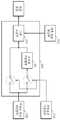
도 2는 도 1에 도시된 레지듀 생성부(120)의 구성도이다.2 is a block diagram of the
도 2를 참조하면, 도 1에 도시된 레지듀 생성부(120)는 단일 모드 레지듀 생 성부(1211) 및 복합 모드 레지듀 생성부(1212)로 구성된다.Referring to FIG. 2, the
단일 모드 레지듀 생성부(1211)는 최적 모드 선택부(110)에 의해 선택된 예측 모드가 단일 예측 모드이면, 단일 예측 모드에 따라 현재 영상 내의 공간적 중복성을 제거하는 공간상 예측(이하, "단일 인트라 예측"이라 함)을 수행하거나, 단일 예측 모드에 따라 현재 영상과 참조 영상간의 시간적 중복성을 제거하는 시간상 예측(이하, "단일 인터 예측"이라 함)을 수행함으로서 예측 영상을 생성한다. 이어서, 단일 모드 레지듀 생성부(1211)는 현재 영상과 이와 같이 생성된 예측 영상의 차이에 해당하는 레지듀를 생성한다.If the prediction mode selected by the optimal
보다 상세하게 설명하면, 단일 모드 레지듀 생성부(1211)는 현재 영상의 색 성분들 각각의 매크로블록에 일률적으로 적용되는 크기로 색 성분들 각각의 매크로블록을 분할하고, 이와 같이 분할된 색 성분들 각각의 블록 별로 색 성분들 각각의 블록에 일률적으로 적용되는 참조 영상과 현재 영상간의 움직임 벡터들을 결정하고, 이와 같이 결정된 움직임 벡터들을 사용하여 참조 영상으로부터 현재 영상에 대한 예측 영상을 생성함으로써 단일 인터 예측을 수행한다.In more detail, the single mode
즉, 단일 모드 레지듀 생성부(1211)는 현재 영상의 색 성분들 각각의 매크로블록을 동일한 크기로 분할하고, 이와 같이 분할된 색 성분들 각각의 블록 별로 동일한 움직임 벡터들을 결정하고, 이와 같이 결정된 움직임 벡터들을 사용하여 참조 영상으로부터 현재 영상에 대한 예측 영상을 생성함으로써 단일 인터 예측을 수행한다.That is, the single mode
도 3은 인터 예측에서의 매크로블록의 분할 방법을 도시한 도면이다.3 is a diagram illustrating a method of dividing a macroblock in inter prediction.
도 3을 참조하면, 인터 예측에서의 매크로블록의 경우, 16x16 크기의 매크로블록을 16x16, 16x8, 8x16, 8x16, 8x8 등의 다양한 크기로 분할한 후, 이와 같이 분할된 블록들 별로 움직임 벡터가 결정된다. 나아가, 8x8 크기의 블록을 다시 8x8, 8x4, 4x8, 4x4 등의 더 작은 크기로 분할한 후, 이와 같이 분할된 블록들 별로 움직임 벡터가 결정될 수도 있다. 매크로블록이 더 작게 분할될수록, 레지듀에 현재 영상과 참조 영상간의 세밀한 움직임이 포함될 수 있다.Referring to FIG. 3, in the case of a macroblock in inter prediction, a 16x16 macroblock is divided into various sizes such as 16x16, 16x8, 8x16, 8x16, and 8x8, and then a motion vector is determined for each of the divided blocks. do. Furthermore, after dividing an 8x8 block into smaller sizes such as 8x8, 8x4, 4x8, and 4x4, a motion vector may be determined for each of the divided blocks. The smaller the macroblock is divided, the finer motion between the current picture and the reference picture may be included in the residue.
YCoCg 색 공간을 예로 들면, 단일 모드 레지듀 생성부(1211)는 Y 성분의 매크로블록, Co 성분의 매크로블록, Cg 성분의 매크로블록 모두를 동일한 크기로 분할하고, 예를 들면, Y 성분의 매크로블록, Co 성분의 매크로블록, Cg 성분의 매크로블록 모두를 8x8 크기로 분할하고, 이와 같이 분할된 Y 성분의 블록, Co 성분의 블록, Cg 성분의 블록 별로 동일한 움직임 벡터를 결정한다. 또한, RGB 색 공간을 예로 들면, 단일 모드 레지듀 생성부(1211)는 R 성분의 매크로블록, G 성분의 매크로블록, B 성분의 매크로블록 모두를 동일한 크기로 분할하고, 예를 들면, R 성분의 매크로블록, G 성분의 매크로블록, B 성분의 매크로블록 모두를 8x8 크기로 분할하고, 이와 같이 분할된 R 성분의 블록, G 성분의 블록, B 성분의 블록 별로 동일한 움직임 벡터를 결정한다.Taking the YCoCg color space as an example, the single mode
또한, 단일 모드 레지듀 생성부(1211)는 현재 영상의 색 성분들 각각의 매크로블록에 일률적으로 적용되는 크기로 색 성분들 각각의 매크로블록을 분할하고, 이와 같이 분할된 색 성분들 각각의 블록 별로 색 성분들 각각의 블록에 일률적으로 적용되는 예측 방향을 결정하고, 이와 같이 결정된 예측 방향들을 사용하여 복 원 영상 생성부(180)에 의해 생성된 복원 영상 내의 인접 화소들로부터 현재 영상을 구성하는 블록들을 예측하고, 이와 같이 예측된 블록들로 구성된 예측 영상을 생성함으로써 단일 인트라 예측을 수행한다.In addition, the single mode
즉, 단일 모드 레지듀 생성부(1211)는 현재 영상의 색 성분들 각각의 매크로블록을 동일한 크기로 분할하고, 이와 같이 분할된 색 성분들 각각의 블록 별로 동일한 예측 방향을 결정하고, 이와 같이 결정된 예측 방향들을 사용하여 복원 영상 생성부(180)에 의해 생성된 복원 영상 내의 인접 화소들로부터 현재 영상을 구성하는 블록들을 예측하고, 이와 같이 예측된 블록들로 구성된 예측 영상을 생성함으로써 단일 인트라 예측을 수행한다.That is, the single mode
도 4는 인트라 예측에서의 예측 모습을 도시한 도면이다.4 is a diagram illustrating a prediction state in intra prediction.
도 4를 참조하면, 16x16 크기의 매크로블록을 4x4 크기로 분할한 후, 이와 같이 분할된 블록들 별로 9 개의 예측 방향들을 사용하여 예측 영상이 생성된다. 아니면, 16x16 크기의 매크로블록에 대해 4 개의 예측 방향들을 사용하여 예측 영상이 생성될 수도 있다. 전자의 경우를 보다 상세히 설명하면, 4x4 크기의 블록들 Pa, Pb, ..., Pq을 예측하기 위해, 복원 영상 내 공간상 인접 화소 P0, P1, ..., P12를 이용한다(41). 0부터 8까지의 9 개의 예측 방향을 사용하여 인접 화소 P0, P1, ..., P12로부터 Pa, Pb, ..., Pq를 예측한다(42). 0의 방향을 예로 들면, 인접 화소 P1, P2, P3, 및 P4를 0의 방향에 해당하는 수직 하강 방향으로 투영함으로써 Pa, Pe, Pi, 및 Pm은 P1로부터 예측하고, Pb, Pf, Pj, 및 Pn은 P2로부터 예측하고, Pc, Pg, Pk, 및 Pd는 P3로부터 예측하고, Pd, Ph, Pl, 및 Pq는 P4로부터 예측한다. 다른 방향의 경우도 마찬가지로 상기된 바와 같은 투영에 의해 Pa, Pb, ..., Pq가 예측될 수 있다.Referring to FIG. 4, after a 16x16 macroblock is divided into 4x4 sizes, a prediction image is generated using nine prediction directions for each of the divided blocks. Alternatively, a prediction image may be generated using four prediction directions for a 16 × 16 macroblock. In the former case, in order to predict 4x4 blocks Pa, Pb, ..., Pq, adjacent pixels P0, P1, ..., P12 in the reconstructed image are used (41). Pa, Pb, ..., Pq are predicted from the adjacent pixels P0, P1, ..., P12 using nine prediction directions from 0 to 8 (42). Taking the direction of 0 as an example, Pa, Pe, Pi, and Pm are predicted from P1 by projecting adjacent pixels P1, P2, P3, and P4 in the vertical falling direction corresponding to the direction of 0, and Pb, Pf, Pj, And Pn is predicted from P2, Pc, Pg, Pk, and Pd are predicted from P3, and Pd, Ph, Pl, and Pq are predicted from P4. In the other direction as well, Pa, Pb, ..., Pq can be predicted by the projection as described above.
YCoCg 색 공간을 예로 들면, 단일 모드 레지듀 생성부(1211)는 Y 성분의 매크로블록, Co 성분의 매크로블록, Cg 성분의 매크로블록 모두를 동일한 크기로 분할하고, 예를 들면, Y 성분의 매크로블록, Co 성분의 매크로블록, Cg 성분의 매크로블록 모두를 4x4 크기로 분할하고, 이와 같이 분할된 Y 성분의 블록, Co 성분의 블록, Cg 성분의 블록 별로 동일한 예측 방향을 결정한다. 또한, RGB 색 공간을 예로 들면, 단일 모드 레지듀 생성부(1211)는 R 성분의 매크로블록, G 성분의 매크로블록, B 성분의 매크로블록 모두를 동일한 크기로 분할하고, 예를 들면, R 성분의 매크로블록, G 성분의 매크로블록, B 성분의 매크로블록 모두를 4x4 크기로 분할하고, 이와 같이 분할된 R 성분의 블록, G 성분의 블록, B 성분의 블록 별로 동일한 예측 방향을 결정한다.Taking the YCoCg color space as an example, the single mode
상기된 바와 같이, 단일 모드 레지듀 생성부(1211)는 서로 다른 색 성분들 각각에 동일한 시간상 예측 방식 및 동일한 공간상 예측 방식을 적용하기 때문에 색 성분들 각각의 레지듀간의 유사성이 높아지게 된다. 또한, 블록의 사이즈, 움직임 벡터, 예측 방향 등이 모든 색 성분들에 일률적으로 적용되기 때문에, 색 성분들마다 이러한 정보를 부호화시켜 보낼 필요 없이, 모든 색 성분들에 대하여 한번만 이러한 정보를 부호화시켜 보내면 되기 때문에 전체적인 부호화 효율을 높일 수 있다는 장점이 있다.As described above, since the single mode
복합 모드 레지듀 생성부(1212)는 최적 모드 선택부(110)에 의해 선택된 예 측 모드가 복합 예측 모드이면, 복합 예측 모드에 따라 현재 영상과 참조 영상간의 시간적 중복성을 제거하는 시간상 예측(이하, "복합 인터 예측"이라 함)을 수행하거나, 현재 영상의 색 성분들 각각의 매크로블록에 독립적으로 적용되는 예측 모드에 따라 현재 영상 내의 공간적 중복성을 제거하는 공간상 예측(이하, "복합 인트라 예측"이라 함)을 수행함으로서 예측 영상을 생성한다. 또한, 복합 모드 레지듀 생성부(1212)는 현재 영상과 이와 같이 생성된 예측 영상의 차이에 해당하는 레지듀를 생성한다.If the prediction mode selected by the optimal
보다 상세하게 설명하면, 복합 모드 레지듀 생성부(1212)는 현재 영상의 색 성분들 각각의 매크로블록에 독립적으로 적용되는 크기로 색 성분들 각각의 매크로블록을 분할하고, 이와 같이 분할된 색 성분들 각각의 블록 별로 색 성분들 각각의 블록에 독립적으로 적용되는 참조 영상과 현재 영상간의 움직임 벡터들을 결정하고, 이와 같이 결정된 움직임 벡터들을 사용하여 참조 영상으로부터 현재 영상에 대한 예측 영상을 생성함으로써 복합 인터 예측을 수행한다.In more detail, the complex mode
즉, 복합 모드 레지듀 생성부(1212)는 현재 영상의 색 성분들 각각의 매크로블록을 서로 다른 크기로 분할하고, 이와 같이 분할된 색 성분들 각각의 블록 별로 서로 다른 움직임 벡터들을 결정하고, 이와 같이 결정된 움직임 벡터들을 사용하여 참조 영상으로부터 현재 영상에 대한 예측 영상을 생성함으로써 복합 인터 예측을 수행한다. 물론, 복합 모드 레지듀 생성부(1212)는 현재 영상의 색 성분들 각각의 매크로블록에 독립적으로 적용되는 예측 모드에 따라 인터 예측을 수행하기 때문에 현재 영상의 색 성분들 각각의 매크로블록을 동일한 크기로 분할하고, 이와 같이 분할된 색 성분들 각각의 블록 별로 동일한 움직임 벡터들을 결정할 수도 있다.That is, the complex mode
YCoCg 색 공간을 예로 들면, 복합 모드 레지듀 생성부(1212)는 Y 성분의 매크로블록, Co 성분의 매크로블록, Cg 성분의 매크로블록을 서로 다른 크기로 분할하고, 예를 들면, Y 성분의 매크로블록을 4x4, Co 성분의 매크로블록을 8x8, Cg 성분의 매크로블록을 8x8의 크기로 분할하고, 이와 같이 분할된 Y 성분의 블록, Co 성분의 블록, Cg 성분의 블록 별로 서로 다른 움직임 벡터들을 결정한다. 또한, RGB 색 공간을 예로 들면, 복합 모드 레지듀 생성부(1212)는 R 성분의 매크로블록, G 성분의 매크로블록, B 성분의 매크로블록을 서로 다른 크기로 분할하고, 예를 들면, R 성분의 매크로블록을 8x8, G 성분의 매크로블록을 4x4, B 성분의 매크로블록을 8x8의 크기로 분할하고, 이와 같이 분할된 R 성분의 블록, G 성분의 블록, B 성분의 블록 별로 서로 다른 움직임 벡터들을 결정한다.Taking the YCoCg color space as an example, the complex mode
또한, 복합 모드 레지듀 생성부(1212)는 현재 영상의 색 성분들 각각의 매크로블록에 독립적으로 적용되는 크기로 색 성분들 각각의 매크로블록을 분할하고, 이와 같이 분할된 색 성분들 각각의 블록 별로 색 성분들 각각의 블록에 독립적으로 적용되는 예측 방향을 결정하고, 이와 같이 결정된 예측 방향들을 사용하여 복원 영상 생성부(180)에 의해 생성된 복원 영상 내의 인접 화소들로부터 현재 영상을 구성하는 블록들을 예측하고, 이와 같이 예측된 블록들로 구성된 예측 영상을 생성함으로써 복합 인트라 예측을 수행한다.In addition, the composite mode
즉, 복합 모드 레지듀 생성부(1212)는 현재 영상의 색 성분들 각각의 매크로블록을 서로 다른 크기로 색 성분들 각각의 매크로블록을 분할하고, 이와 같이 분 할된 색 성분들 각각의 블록 별로 서로 다른 예측 방향을 결정하고, 이와 같이 결정된 예측 방향들을 사용하여 복원 영상 생성부(180)에 의해 생성된 복원 영상 내의 인접 화소들로부터 현재 영상을 구성하는 블록들을 예측하고, 이와 같이 예측된 블록들로 구성된 예측 영상을 생성함으로써 복합 인트라 예측을 수행한다. 물론, 복합 모드 레지듀 생성부(1212)는 현재 영상의 색 성분들 각각의 매크로블록에 독립적으로 적용되는 예측 모드에 따라 인트라 예측을 수행하기 때문에 현재 영상의 색 성분들 각각의 매크로블록을 동일한 크기로 분할하고, 이와 같이 분할된 색 성분들 각각의 블록 별로 동일한 움직임 벡터들을 결정할 수도 있다.That is, the complex mode
YCoCg 색 공간을 예로 들면, 복합 모드 레지듀 생성부(1212)는 Y 성분의 매크로블록, Co 성분의 매크로블록, Cg 성분의 매크로블록을 서로 다른 크기로 분할하고, 예를 들면, Y 성분의 매크로블록을 4x4, Co 성분의 매크로블록을 16x16, Cg 성분의 매크로블록을 16x16의 크기로 분할하고, 이와 같이 분할된 Y 성분의 블록, Co 성분의 블록, Cg 성분의 블록 별로 서로 다른 예측 방향을 결정한다. 또한, RGB 색 공간을 예로 들면, 복합 모드 레지듀 생성부(1212)는 R 성분의 매크로블록, G 성분의 매크로블록, B 성분의 매크로블록을 서로 다른 크기로 분할하고, 예를 들면, R 성분의 매크로블록을 16x16, G 성분의 매크로블록을 4x4, B 성분의 매크로블록을 16x16의 크기로 분할하고, 이와 같이 분할된 R 성분의 블록, G 성분의 블록, B 성분의 블록 별로 서로 다른 예측 방향을 결정한다.Taking the YCoCg color space as an example, the complex mode
나아가, 복합 모드 레지듀 생성부(1212)는 현재 영상의 색 성분들 각각의 매크로블록 별로 복합 인터 예측 또는 복합 인트라 예측을 수행할 수도 있다. 즉, 복 합 모드 레지듀 생성부(1212)는 현재 영상의 색 성분들 각각의 매크로블록 중 어느 하나의 색 성분의 매크로 블록에 대해서는 복합 인터 예측을 수행하고, 다른 색 성분의 매크로블록에 대해서는 복합 인트라 예측을 수행할 수도 있다.Furthermore, the complex
상기된 바와 같이, 복합 모드 레지듀 생성부(1212)는 서로 다른 색 성분들 간에 서로 다른 시간상 예측 방식과 서로 다른 공간상 예측 방식을 수행하기 때문에 색 성분들 간에 유사성이 별로 없다면, 서로 간에 각각 독립적인 부호화 방법을 사용하여 각 색 성분에 가장 적합한 방법을 사용하도록 함으로써 예측 부호화를 효과적으로 수행하여 결국 전체적인 부호화 효율을 높일 수 있으나, 색 성분들에 독립적으로 적용되는 블록의 사이즈, 움직임 벡터, 및 예측 방향 등을 한번만 부호화하여 보내면 되기 때문에 부호화 효율을 높일 수 있다.As described above, since the complex mode
도 5는 도 1에 도시된 레지듀 생성부(120)의 다른 구성도이다.5 is another configuration diagram of the
도 5를 참조하면, 도 5에 도시된 레지듀 생성부(120)는 단일 모드 레지듀 생성부(1221), 레지듀 변환부(1222), 및 복합 모드 레지듀 생성부(1223)로 구성된다. 단일 모드 레지듀 생성부(1221) 및 복합 모드 레지듀 생성부(1223)는 도 2에 도시된 단일 모드 레지듀 생성부(1211) 및 복합 모드 레지듀 생성부(1212)와 동일한 기능을 수행한다.Referring to FIG. 5, the
그런데, 단일 모드 레지듀 생성부(1221)에서의 인터 예측 또는 인트라 예측 이후에도 색 성분들간에는 중복성이 남아있다. 레지듀 변환부(1222)는 이러한 색 성분들간의 중복성을 제거하는 역할을 한다. 단일 모드 레지듀 생성부(1221)에 의해 생성된 레지듀와 레지듀 변환부(1222)에 의해 생성된 레지듀를 구별하기 위하 여, 전자를 "제 1 레지듀"라 칭하고, 후자를 "제 2 레지듀"라 칭하기로 한다.However, even after inter prediction or intra prediction in the single mode
레지듀 변환부(1222)는 최적 모드 선택부(110)에 의해 선택된 예측 모드가 레지듀 변환 모드이면, 단일 모드 레지듀 생성부(1221)에 의해 생성된 제 1 레지듀들간의 차이에 해당하는 제 2 레지듀들을 생성한다.If the prediction mode selected by the optimal
도 6은 도 1에 도시된 레지듀 생성부(120)의 또 다른 구성도이다.6 is another configuration diagram of the
도 6을 참조하면, 도 6에 도시된 레지듀 생성부(120)는 단일 모드 레지듀 생성부(1231), RCT(Residual Color Transformation) 변환부(1232), IPP(Inter-Plane Prediction) 변환부(1233), 및 RCP(Residual Color Prediction) 변환부(1234), 및 복합 모드 레지듀 생성부(1235)로 구성된다. 단일 모드 레지듀 생성부(1231) 및 복합 모드 레지듀 생성부(1235)는 도 2에 도시된 단일 모드 레지듀 생성부(1211) 및 복합 모드 레지듀 생성부(1212)와 동일한 기능을 수행한다. 상기된 바와 마찬가지로, 단일 모드 레지듀 생성부(1231)에 의해 생성된 레지듀와 RCT 변환부(1232), IPP 변환부(1233), 및 RCP 변환부(1234)에 의해 생성된 레지듀를 구별하기 위하여, 전자를 "제 1 레지듀"라 칭하고, 후자를 "제 2 레지듀"라 칭하기로 한다.Referring to FIG. 6, the
단일 모드 레지듀 생성부(1221)에 의해 생성된 제 1 레지듀들간의 차이에 해당하는 제 2 레지듀들을 생성하는 방식들로는 RCT 변환 방식, IPP 변환 방식, RCP 변환 방식이 있다. RCT 변환은 YCoCg 색 공간에서 제 2 레지듀들을 생성하는 것이고, IPP 변환은 RGB 색 공간에서 제 2 레지듀들을 생성하는 것이고, RCP 변환은 IPP 변환과 유사하나, G 성분의 레지듀를 예측자로 사용할 때에 소정의 필터링을 통하여 잡음을 제거한 후에 IPP 변환과 동일한 변환을 적용한다.Methods of generating second residues corresponding to the difference between the first residues generated by the single mode
RCT 변환부(1232)는 최적 모드 선택부(110)에 의해 선택된 예측 모드가 RCT 변환 모드이면, YCoCg 색 공간에서 다음의 수학식 3을 이용하여 Y 성분, Co 성분, Cg 성분 각각의 제 1 레지듀들간의 차이에 해당하는 제 2 레지듀들을 생성한다. 특히, Y = (R + 2G + B) >> 2, Co = (R - B) >> 1, Cg = (-R + 2G - B) >> 2의 관계에 있다.If the prediction mode selected by the optimal

여기에서, △X는 제 1 레지듀들을 의미하고, △2X는 제 2 레지듀들을 의미한다. 또한, 표기 ">>"는 우측 시프트 연산(right shift operation)을 의미하며, 대략적으로 나누기 2가 된다. 또한, 변수 t는 임시적인 계산 목적으로 사용된다.Here, ΔX means first residues, and Δ2 X means second residues. In addition, the notation ">>" means a right shift operation, which is approximately divided by two. In addition, the variable t is used for temporary calculation purposes.
IPP 변환부(1233)는 최적 모드 선택부(110)에 의해 선택된 예측 모드가 IPP 변환 모드이면, 이 IPP 변환 모드에 따라 RGB 색 공간에서 다음의 수학식 4를 이용하여 R 성분, G 성분, B 성분 각각의 제 1 레지듀들간의 차이에 해당하는 제 2 레지듀들을 생성한다.If the prediction mode selected by the optimal

여기에서, △X는 제 1 레지듀들을 의미하고, △2X는 제 2 레지듀들을 의미한다. 또한, △X'는 복원된 제 1 레지듀들을 의미한다. 특히, 수학식 2는 G 성분이 영상 정보를 많이 가지고 있을 때 효과적이며, R 성분 또는 B 성분을 주된(dominant) 성분으로 제 2 레지듀들을 계산할 수도 있다.Here, ΔX means first residues, and Δ2 X means second residues. Also, ΔX ′ means the restored first residues. In particular,
RCP 변환부(1234)는 최적 모드 선택부(110)에 의해 선택된 예측 모드가 RCP 변환 모드이면, RCP 변환 모드에 따라 RGB 색 공간에서 다음의 수학식 5와 같은 5-탭(tap) 필터를 사용하여 R 성분, G 성분, B 성분 각각의 잡음을 제거한 후, R 성분, G 성분, B 성분 각각의 제 1 레지듀들간의 차이에 해당하는 제 2 레지듀들을 생성한다.If the prediction mode selected by the optimal

또한, RCP 변환부(1234)는 RGB 색 공간에서 다음의 수학식 6과 같은 3-탭 필터를 사용하여 R 성분, G 성분, B 성분 각각의 잡음을 제거한 후, R 성분, G 성분, B 성분 각각의 제 1 레지듀들간의 차이에 해당하는 제 2 레지듀들을 생성한다.In addition, the

상기된 수학식 5 및 수학식 6에서 abs(x)는 x의 절대값을 의미하고, sign(s)는 다음의 수학식 7을 의미한다.In

도 7은 본 발명에 따른 바람직한 일 실시예에 적용되는 5-탭 필터와 3-탭 필터를 도시한 도면이다.7 is a diagram illustrating a 5-tap filter and a 3-tap filter applied to an exemplary embodiment of the present invention.
도 7을 참조하면, 본 실시예에 적용되는 5-탭 필터는 예측자로 사용할 화소를 중심으로 주변의 4개의 화소들을 사용하고, 3-탭 필터는 예측자로 사용할 화소를 중심으로 주변의 좌, 우 두 개의 화소들을 사용한다. 다만, 상기된 수학식 5 및 수학식 6에서와 같이 가중치를 두어 사용할 수 있다.Referring to FIG. 7, the 5-tap filter applied to the present embodiment uses four pixels around the pixel to be used as the predictor, and the 3-tap filter uses the left, right peripheral to the pixel to be used as the predictor. Use two pixels. However, weights may be used as in
도 8은 도 1에 도시된 레지듀 생성부(120)의 또 다른 구성도이다.8 is another configuration diagram of the
도 8을 참조하면, 도 6에 도시된 레지듀 생성부(120)는 복합 모드 레지듀 생성부(1241) 및 레지듀 변환부(1242)로 구성된다. 복합 모드 레지듀 생성부(1241)는 도 2에 도시된 복합 모드 레지듀 생성부(1212)와 동일한 기능을 수행한다.Referring to FIG. 8, the
그런데, 복합 모드 레지듀 생성부(1241)에서의 인터 예측 또는 인트라 예측 이후에도 색 성분들간에는 중복성이 남아있다. 레지듀 변환부(1242)는 이러한 색 성분들간의 중복성을 제거하는 역할을 한다. 단일 모드 레지듀 생성부(1241)에 의해 생성된 레지듀와 레지듀 변환부(1242)에 의해 생성된 레지듀를 구별하기 위하여, 전자를 "제 1 레지듀"라 칭하고, 후자를 "제 2 레지듀"라 칭하기로 한다.However, even after inter prediction or intra prediction in the composite mode
레지듀 변환부(1242)는 최적 모드 선택부(110)에 의해 선택된 예측 모드가 레지듀 변환 모드이면, 레지듀 변환 모드에 따라 복합 모드 레지듀 생성부(1241)에 의해 생성된 제 1 레지듀들간의 차이에 해당하는 제 2 레지듀들을 생성한다. 다만, 복합 모드 레지듀 생성부(1241)에서의 인터 예측 또는 인트라 예측 이후에도 색 성분들간에는 중복성이 남아 있을 수 있으나, 단일 모드 방식에 비해 색 성분들간의 유사성이 낮기 때문에, 레지듀 변환부(1242)에서의 압축 효율은 레지듀 변환부(1222)에서의 압축 효율보다는 떨어진다.If the prediction mode selected by the optimum
도 9는 도 2에 도시된 복원 영상 생성부(180)의 구성도이다.9 is a configuration diagram of the
도 9를 참조하면, 도 2에 도시된 복원 영상 생성부(180)는 레지듀 역변환부(181) 및 예측 보상부(182)로 구성된다.Referring to FIG. 9, the
레지듀 역변환부(181)는 주파수 공간 역변환부(170)에 의해 복원된 제 2 레지듀들간의 합산에 해당하는 제 1 레지듀들을 생성한다. 예를 들면, 레지듀 역변환부(181)는 다음의 수학식 8을 이용하여 Y 성분, Co 성분, Cg 성분 각각의 제 2 레지듀들간의 합산에 해당하는 Y 성분, Co 성분, Cg 성분 각각의 제 1 레지듀들을 생성한다.The residue

여기에서, △X'는 복원된 제 1 레지듀들을 의미하고, △2X'는 복원된 제 2 레지듀들을 의미한다.Here, ΔX ′ means restored first residues, and Δ2 X ′ means restored second residues.
아니면, 레지듀 역변환부(181)는 다음의 수학식 9를 이용하여 R 성분, G 성분, B 성분 각각의 제 2 레지듀들간의 합산에 해당하는 R 성분, G 성분, B 성분 각각의 제 1 레지듀들을 생성한다.Alternatively, the residue

여기에서, △X'는 복원된 제 1 레지듀들을 의미하고, △2X'는 복원된 제 2 레지듀들을 의미한다.Here, ΔX ′ means restored first residues, and Δ2 X ′ means restored second residues.
예측 보상부(182)는 레지듀 생성부(120)에 의해 생성된 예측 영상과 레지듀 역변환부(181)에 의해 생성된 제 1 레지듀들간의 합산에 해당하는 복원 영상을 생성한다. 예를 들면, 예측 보상부(182)는 Y 성분, Co 성분, 및 Cg 성분마다 레지듀 생성부(120)에 의해 생성된 예측 영상과 레지듀 역변환부(181)??에 의해 생성된 제 1 레지듀들간의 합산을 산출함으로서 YCoCg 색 공간에서의 복원 영상을 생성한다. 아니면, 예측 보상부(182)는 R 성분, G 성분, 및 B 성분마다 레지듀 생성부(120)에 의해 생성된 예측 영상과 레지듀 역변환부(181)??에 의해 생성된 제 1 레지듀들간의 합산을 산출함으로서 RGB 색 공간에서의 복원 영상을 생성한다.The
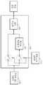
도 10은 본 발명의 바람직한 일 실시예에 따른 동영상 복호화 장치의 구성도이다.10 is a block diagram of a video decoding apparatus according to an embodiment of the present invention.
도 10을 참조하면, 본 실시예에 따른 동영상 복호화 장치는 엔트로피 복호화 부(210), 역양자화부(220), 주파수 공간 역변환부(230), 예측 화면 생성부(240) 및 복원 영상 생성부(250)로 구성된다.Referring to FIG. 10, the video decoding apparatus according to the present embodiment includes an
엔트로피 복호화부(210)는 도 1에 도시된 동영상 부호화 장치로부터 출력된 비트 스트림을 엔트로피 복호화함으로서 현재 영상에 해당하는 정수 값들 및 현재 영상의 색 성분들 각각의 블록에 최적인 예측 모드를 나타내는 정보를 복원한다. 여기에서, 현재 영상의 색 성분들 각각의 블록에 최적인 예측 모드는 동영상 부호화 장치에서 사용된 예측 모드이다.The
역양자화부(220)는 엔트로피 복호화부(210)에 의해 복원된 정수 값들을 역양자화함으로서 주파수 성분 값들을 복원한다. 즉, 역양자화부(220)는 엔트로피 복호화부(210)에 의해 복원된 정수 값들에 양자화 파라미터를 곱함으로서 주파수 성분 값들을 복원한다.The
주파수 공간 역변환부(230)는 역양자화부(220)에 의해 복원된 주파수 성분 값들을 주파수 공간으로부터 색 공간으로 변환함으로서 현재 영상과 예측 영상의 차이에 해당하는 레지듀들을 생성한다. 아니면, 주파수 공간 역변환부(230)는 역양자화부(220)에 의해 복원된 주파수 성분 값들을 주파수 공간으로부터 색 공간으로 변환함으로서 색 성분들 각각의 제 1 레지듀간의 차이에 해당하는 제 2 레지듀들을 복원한다.The frequency space
예측 영상 생성부(240)는 색 성분들 각각의 매크로블록 별로 엔트로피 복호화부(210)에 의해 복원된 정보가 나타내는 예측 모드에 따라 현재 영상에 대한 예측 영상을 생성한다.The
복원 영상 생성부(250)는 예측 영상 생성부(240)에 의해 생성된 예측 영상과 주파수 공간 역변환부(230)에 의해 복원된 레지듀들간의 합산에 해당하는 복원 영상을 생성한다. 아니면, 복원 영상 생성부(250)는 주파수 공간 역변환부(230)에 의해 복원된 제 2 레지듀들간의 합산에 해당하는 제 1 레지듀들을 생성하고, 예측 영상 생성부(240)에 의해 생성된 예측 영상과 이와 같이 생성된 제 1 레지듀들간의 합산에 해당하는 복원 영상을 생성한다.The
도 11은 도 10에 시된 예측 영상 생성부(240)의 구성도이다.FIG. 11 is a diagram illustrating the configuration of the
도 11을 참조하면, 도 10에 도시된 예측 영상 생성부(240)는 단일 모드 예측 영상 생성부(240) 및 복합 모드 예측 영상 생성부(240)로 구성된다.Referring to FIG. 11, the
단일 모드 예측 영상 생성부(240)는 엔트로피 복호화부(210)에 의해 복원된 정보가 단일 예측 모드를 나타내면, 단일 인트라 예측 또는 단일 인터 예측을 수행함으로서 예측 영상을 생성한다. 보다 상세하게 설명하면, 단일 모드 예측 영상 생성부(240)는 현재 영상의 색 성분들 각각의 매크로블록에 일률적으로 적용되는 크기로 분할된 블록 별로 색 성분들 각각의 블록에 일률적으로 적용되는 참조 영상과 현재 영상간의 움직임 벡터들을 사용하여 참조 영상으로부터 현재 영상에 대한 예측 영상을 생성한다. 즉, 단일 모드 예측 영상 생성부(240)는 현재 영상의 색 성분들 각각의 매크로블록에 대해 동일한 크기로 분할된 블록 별로 동일한 움직임 벡터들을 사용하여 참조 영상으로부터 현재 영상에 대한 예측 영상을 생성한다.If the information reconstructed by the
또한, 단일 모드 예측 영상 생성부(240)는 현재 영상의 색 성분들 각각의 매크로블록에 일률적으로 적용되는 크기로 분할된 블록 별로 색 성분들 각각의 블록 에 일률적으로 적용되는 예측 방향들을 사용하여 복원 영상 생성부(250)에 의해 생성된 복원 영상 내의 인접 화소들로부터 현재 영상을 구성하는 블록들을 예측하고, 이와 같이 예측된 블록들로 구성된 예측 영상을 생성한다. 즉, 단일 모드 레지듀 생성부()는 현재 영상의 색 성분들 각각의 매크로블록에 대해 동일한 크기로 분할된 블록들 별로 동일한 예측 방향들을 사용하여 복원 영상 생성부(250)에 의해 생성된 복원 영상 내의 인접 화소들로부터 현재 영상을 구성하는 블록들을 예측하고, 이와 같이 예측된 블록들로 구성된 예측 영상을 생성한다.In addition, the single mode
복합 모드 예측 영상 생성부(240)는 엔트로피 복호화부(210)에 의해 복원된 정보가 복합 예측 모드를 나타내면, 복합 인터 예측 또는 복합 인트라 예측을 수행함으로서 예측 영상을 생성한다. 보다 상세하게 설명하면, 복합 모드 예측 영상 생성부(240)는 현재 영상의 색 성분들 각각의 매크로블록에 독립적으로 적용되는 크기로 분할된 블록 별로 색 성분들 각각의 블록에 독립적으로 적용되는 참조 영상과 현재 영상간의 움직임 벡터들을 사용하여 참조 영상으로부터 현재 영상에 대한 예측 영상을 생성한다. 즉, 복합 모드 예측 영상 생성부(240)는 현재 영상의 색 성분들 각각의 매크로블록에 대해 서로 다른 크기로 분할된 색 성분들 각각의 블록 별로 서로 다른 움직임 벡터들을 사용하여 참조 영상으로부터 현재 영상에 대한 예측 영상을 생성한다.If the information reconstructed by the
또한, 복합 모드 예측 영상 생성부(240)는 현재 영상의 색 성분들 각각의 매크로블록에 독립적으로 적용되는 크기로 분할된 블록 별로 색 성분들 각각의 블록에 일률적으로 적용되는 예측 방향들을 사용하여 복원 영상 생성부(250)에 의해 생 성된 복원 영상 내의 인접 화소들로부터 현재 영상을 구성하는 블록들을 예측하고, 이와 같이 예측된 블록들로 구성된 예측 영상을 생성함으로써 복합 인트라 예측을 수행한다. 즉, 복합 모드 예측 영상 생성부(240)는 현재 영상의 색 성분들 각각의 매크로블록에 대해 서로 다른 크기로 분할된 블록 별로 서로 다른 예측 방향들을 사용하여 복원 영상 생성부(250)에 의해 생성된 복원 영상 내의 인접 화소들로부터 현재 영상을 구성하는 블록들을 예측하고, 이와 같이 예측된 블록들로 구성된 예측 영상을 생성한다.In addition, the composite mode
도 12는 도 10에 도시된 복원 영상 생성부(250)의 구성도이다.12 is a configuration diagram of the
도 12를 참조하면, 도 10에 도시된 복원 영상 생성부(250)는 레지듀 역변환부(251) 및 예측 보상부(252)로 구성된다.Referring to FIG. 12, the
레지듀 역변환부(251)는 엔트로피 복호화부(210)에 의해 복원된 정보가 레지듀 변환 모드를 나타내면, 주파수 공간 역변환부(230)에 의해 복원된 제 2 레지듀들간의 합산에 해당하는 제 1 레지듀들을 생성한다. 예를 들면, 레지듀 역변환부(251)는 상기된 수학식 8을 이용하여 Y 성분, Co 성분, Cg 성분 각각의 제 2 레지듀들간의 합산에 해당하는 Y 성분, Co 성분, Cg 성분 각각의 제 1 레지듀들을 생성한다. 아니면, 레지듀 역변환부(251)는 상기된 수학식 9를 이용하여 R 성분, G 성분, B 성분 각각의 제 2 레지듀들간의 합산에 해당하는 R 성분, G 성분, B 성분 각각의 제 1 레지듀들을 생성한다.If the information reconstructed by the
예측 보상부(252)는 예측 영상 생성부(240)에 의해 생성된 예측 영상과 레지듀 역변환부(251)에 의해 생성된 제 1 레지듀들간의 합산에 해당하는 복원 영상을 생성한다. 예를 들면, 예측 보상부(252)는 Y 성분, Co 성분, 및 Cg 성분마다 예측 영상 생성부(240)에 의해 생성된 예측 영상과 레지듀 역변환부(251)에 의해 생성된 제 1 레지듀들간의 합산을 산출함으로서 YCoCg 색 공간에서의 복원 영상을 생성한다. 아니면, 예측 보상부(252)는 R 성분, G 성분, 및 B 성분마다 예측 영상 생성부(240)에 의해 생성된 예측 영상과 레지듀 역변환부(251)에 의해 생성된 제 1 레지듀들간의 합산을 산출함으로서 RGB 색 공간에서의 복원 영상을 생성한다.The
도 13은 도 12에 도시된 레지듀 역변환부(251)의 구성도이다.FIG. 13 is a diagram illustrating the residue
도 13을 참조하면, 도 12에 도시된 레지듀 역변환부(251)는 RCT 변환부(2511), IPP 변환부(2512), 및 RCP 변환부(2513)로 구성된다.Referring to FIG. 13, the residue
RCT 변환부(1232)는 엔트로피 복호화부(210)에 의해 복원된 정보가 RCT 변환 모드를 나타내면, 상기된 수학식 8을 이용하여 Y 성분, Co 성분, Cg 성분 각각의 제 2 레지듀들간의 합산에 해당하는 Y 성분, Co 성분, Cg 성분 각각의 제 1 레지듀들을 생성한다.If the information restored by the
IPP 변환부(1233)는 엔트로피 복호화부(210)에 의해 복원된 정보가 IPP 변환 모드를 나타내면, 상기된 수학식 9를 이용하여 R 성분, G 성분, B 성분 각각의 제 2 레지듀들간의 합산에 해당하는 R 성분, G 성분, B 성분 각각의 제 1 레지듀들을 생성한다.When the information restored by the
RCP 변환부(1234)는 엔트로피 복호화부(210)에 의해 복원된 정보가 RCP 변환 모드를 나타내면, 상기된 수학식 9를 이용하여 R 성분, G 성분, B 성분 각각의 제 2 레지듀들간의 합산에 해당하는 R 성분, G 성분, B 성분 각각의 제 1 레지듀들을 생성한다.If the information reconstructed by the
도 14a-14b는 본 발명의 바람직한 일 실시예에 따른 동영상 부호화 방법의 흐름도이다.14A and 14B are flowcharts of a video encoding method, according to an embodiment of the present invention.
도 14a-14b를 참조하면, 본 실시예에 따른 동영상 부호화 방법은 도 1에 도시된 동영상 부호화 장치에서 시계열적으로 처리되는 단계들로 구성된다. 따라서, 이하 생략된 내용이라 하더라도 도 1에 도시된 동영상 부호화 장치에 관하여 이상에서 기술된 내용은 본 실시예에 따른 동영상 부호화 방법에도 적용된다.14A and 14B, the video encoding method according to the present embodiment includes steps that are processed in time series in the video encoding apparatus shown in FIG. 1. Therefore, even if omitted below, the contents described above with respect to the video encoding apparatus shown in FIG. 1 are also applied to the video encoding method according to the present embodiment.
1401 단계에서 동영상 부호화 장치는 샘플 영상에 대해서 모든 가능한 예측 모드들 중 어느 하나를 선택한다. 특히, 하기된 1406 단계로부터 1401 단계로 돌아온 경우에는 동영상 부호화 장치는 모든 가능한 예측 모드들 중 이미 선택된 예측 모드를 제외한 것들 중 어느 하나를 선택한다.In
1402 단계에서 동영상 부호화 장치는 1401 단계에서 선택된 예측 모드에 따라 색 성분들 각각의 매크로블록 별로 현재 영상에 대한 예측 영상을 생성하고, 현재 영상과 예측 영상의 차이에 해당하는 레지듀들을 생성한다. 아니면, 1402 단계에서 동영상 부호화 장치는 1401 단계에서 선택된 예측 모드에 따라 색 성분들 각각의 매크로블록 별로 현재 영상에 대한 예측 영상을 생성하고, 현재 영상과 예측 영상의 차이에 해당하는 제 1 레지듀들을 생성하고, 색 성분들 각각의 제 1 레지듀간의 차이에 해당하는 제 2 레지듀들을 생성한다.In
1403 단계에서 동영상 부호화 장치는 1402 단계에서 생성된 레지듀들을 색 공간으로부터 주파수 공간으로 변환한다. 아니면, 1403 단계에서 동영상 부호화 장 치는 1402 단계에서 생성된 제 2 레지듀들을 색 공간으로부터 주파수 공간으로 변환한다.In operation 1403, the video encoding apparatus converts the residues generated in
1404 단계에서 동영상 부호화 장치는 1403 단계에서 변환된 값들을 양자화한다.In
1405 단계에서 동영상 부호화 장치는 1404 단계에서 양자화된 값들 및 1401 단계에서 선택된 예측 모드를 나타내는 정보를 엔트로피 부호화함으로써 비트 스트림을 생성한다.In
1406 단계에서 동영상 부호화 장치는 1404 단계에서 양자화된 값들을 역양자화함으로서 주파수 성분 값들을 복원한다.In
1407 단계에서 동영상 부호화 장치는 1406 단계에서 복원된 주파수 성분 값들을 주파수 공간으로부터 색 공간으로 변환함으로서 현재 영상과 예측 영상의 차이에 해당하는 레지듀들을 복원한다. 아니면, 1407 단계에서 동영상 부호화 장치는 1406 단계에서 복원된 주파수 성분 값들을 주파수 공간으로부터 색 공간으로 변환함으로서 색 성분들 각각의 제 1 레지듀간의 차이에 해당하는 제 2 레지듀들을 복원한다.In
1408 단계에서 동영상 부호화 장치는 1402 단계에서 생성된 예측 영상과 1407 단계에 의해 복원된 레지듀들간의 합산에 해당하는 복원 영상을 생성한다. 아니면, 1408 단계에서 동영상 부호화 장치는 1407 단계에서 복원된 제 2 레지듀들간의 합산에 해당하는 제 1 레지듀들을 생성하고, 1402 단계에서 의해 생성된 예측 영상과 이와 같이 생성된 제 1 레지듀들간의 합산에 해당하는 복원 영상을 생성한 다.In
1409 단계에서 동영상 부호화 장치는 모든 예측 모드들에 대해서 상기 1401 - 1408 단계가 수행되었는지를 판단하고, 만약 모든 예측 모드들에 대해서 상기 1401 - 1408 단계가 수행된 경우에는 1410 단계로 진행하고, 수행되지 않은 경우에는 1401 단계로 돌아간다.In
1410 단계에서 동영상 부호화 장치는 샘플 영상의 특성, 즉 1401 - 1409 단계에서 수행된 결과에 기초하여 현재 영상의 색 성분들 각각의 매크로블록 별로 색 성분들 각각의 매크로블록에 최적인 예측 모드를 선택한다. 즉, 1410 단계에서 동영상 부호화 장치는 현재 영상의 색 성분들 각각의 매크로블록에 최적인 예측 모드로서 1405 단계에서 생성된 비트 스트림의 양 및 샘플 영상과 1408 단계에서 생성된 복원 영상간의 화질의 왜곡이 가장 적은 예측 모드를 선택한다.In
1411 단계에서 동영상 부호화 장치는 1410 단계에서 선택된 예측 모드에 따라 색 성분들 각각의 매크로블록 별로 현재 영상에 대한 예측 영상을 생성하고, 현재 영상과 예측 영상의 차이에 해당하는 레지듀들을 생성한다. 아니면, 1411 단계에서 동영상 부호화 장치는 1410 단계에서 선택된 예측 모드에 따라 색 성분들 각각의 매크로블록 별로 현재 영상에 대한 예측 영상을 생성하고, 현재 영상과 예측 영상의 차이에 해당하는 제 1 레지듀들을 생성하고, 색 성분들 각각의 제 1 레지듀간의 차이에 해당하는 제 2 레지듀들을 생성한다.In
1412 단계에서 동영상 부호화 장치는 1411 단계에서 생성된 레지듀들을 색 공간으로부터 주파수 공간으로 변환한다. 아니면, 1412 단계에서 동영상 부호화 장 치는 1411 단계에서 생성된 제 2 레지듀들을 색 공간으로부터 주파수 공간으로 변환한다.In
1413 단계에서 동영상 부호화 장치는 1414 단계에서 변환된 값들을 양자화한다.In
1414 단계에서 동영상 부호화 장치는 1413 단계에서 양자화된 값들 및 1410 단계에서 선택된 예측 모드를 나타내는 정보를 엔트로피 부호화함으로써 비트 스트림을 생성한다.In
1415 단계에서 동영상 부호화 장치는 1413 단계에서 양자화된 값들을 역양자화함으로서 주파수 성분 값들을 복원한다.In
1416 단계에서 동영상 부호화 장치는 1415 단계에서 복원된 주파수 성분 값들을 주파수 공간으로부터 색 공간으로 변환함으로서 현재 영상과 예측 영상의 차이에 해당하는 레지듀들을 복원한다. 아니면, 1416 단계에서 동영상 부호화 장치는 1415 단계에서 복원된 주파수 성분 값들을 주파수 공간으로부터 색 공간으로 변환함으로서 색 성분들 각각의 제 1 레지듀간의 차이에 해당하는 제 2 레지듀들을 복원한다.In
1417 단계에서 동영상 부호화 장치는 1411 단계에서 생성된 예측 영상과 1416 단계에 의해 복원된 레지듀들간의 합산에 해당하는 복원 영상을 생성한다. 아니면, 1417 단계에서 동영상 부호화 장치는 1416 단계에서 복원된 제 2 레지듀들간의 합산에 해당하는 제 1 레지듀들을 생성하고, 1411 단계에서 의해 생성된 예측 영상과 이와 같이 생성된 제 1 레지듀들간의 합산에 해당하는 복원 영상을 생성한 다.In
도 15는 본 발명의 바람직한 일 실시예에 따른 동영상 복호화 방법의 흐름도이다.15 is a flowchart of a video decoding method according to an embodiment of the present invention.
도 15를 참조하면, 본 실시예에 따른 동영상 복호화 방법은 도 10에 도시된 동영상 복호화 장치에서 시계열적으로 처리되는 단계들로 구성된다. 따라서, 이하 생략된 내용이라 하더라도 도 10에 도시된 동영상 복호화 장치에 관하여 이상에서 기술된 내용은 본 실시예에 따른 동영상 복호화 방법에도 적용된다.Referring to FIG. 15, the video decoding method according to the present embodiment includes steps that are processed in time series in the video decoding apparatus illustrated in FIG. 10. Therefore, even if omitted below, the contents described above with respect to the video decoding apparatus shown in FIG. 10 are also applied to the video decoding method according to the present embodiment.
1501 단계에서 동영상 복호화 장치는 도 1에 도시된 동영상 부호화 장치로부터 출력된 비트 스트림을 엔트로피 복호화함으로서 현재 영상에 해당하는 정수 값들 및 현재 영상의 색 성분들 각각의 블록에 최적인 예측 모드를 나타내는 정보를 복원한다.In
1502 단계에서 동영상 복호화 장치는 1501 단계에서 복원된 정수 값들을 역양자화함으로서 주파수 성분 값들을 복원한다.In
1503 단계에서 동영상 복호화 장치는 1502 단계에서 복원된 주파수 성분 값들을 주파수 공간으로부터 색 공간으로 변환함으로서 현재 영상과 예측 영상의 차이에 해당하는 레지듀들을 생성한다. 아니면, 1503 단계에서 동영상 복호화 장치는 1502 단계에서 복원된 주파수 성분 값들을 주파수 공간으로부터 색 공간으로 변환함으로서 색 성분들 각각의 제 1 레지듀간의 차이에 해당하는 제 2 레지듀들을 복원한다.In
1504 단계에서 동영상 복호화 장치는 1501 단계에서 복원된 정보가 레지듀 변환 모드를 나타내면 1505 단계로 진행하고, 나타내지 않으면 1506 단계로 진행한다.In
1505 단계에서 동영상 복호화 장치는 1502 단계에서 복원된 제 2 레지듀들간의 합산에 해당하는 제 1 레지듀들을 생성한다. 특히, 1505 단계에서 동영상 복호화 장치는 1501 단계에서 복원된 정보가 RCT 변환 모드를 나타내면, 상기된 수학식 8을 이용하여 Y 성분, Co 성분, Cg 성분 각각의 제 2 레지듀들간의 합산에 해당하는 Y 성분, Co 성분, Cg 성분 각각의 제 1 레지듀들을 생성한다. 또한, 1505 단계에서 동영상 복호화 장치는 1501 단계에서 복원된 정보가 IPP 변환 모드 또는 RCP 변환 모드를 나타내면, 상기된 수학식 9를 이용하여 R 성분, G 성분, B 성분 각각의 제 2 레지듀들간의 합산에 해당하는 R 성분, G 성분, B 성분 각각의 제 1 레지듀들을 생성한다.In
RCP 변환부(1234)는 엔트로피 복호화부(210)에 의해 복원된 정보가 RCP 변환 모드를 나타내면, 상기된 수학식 9를 이용하여 R 성분, G 성분, B 성분 각각의 제 2 레지듀들간의 합산에 해당하는 R 성분, G 성분, B 성분 각각의 제 1 레지듀들을 생성한다.If the information reconstructed by the
1506 단계에서 동영상 복호화 장치는 1501 단계에서 복원된 정보가 단일 예측 모드를 나타내면 1507 단계로 진행하고, 복합 예측 모드를 나타내면 1508 단계로 진행한다.In
1507 단계에서 동영상 복호화 장치는 현재 영상의 색 성분들 각각의 블록에 일률적으로 적용되는 크기로 분할된 블록 별로 색 성분들 각각의 블록에 일률적으 로 적용되는 움직임 벡터들을 사용하여 예측 화면을 생성하거나, 색 성분들 각각의 블록에 일률적으로 적용되는 예측 방향들을 사용하여 예측 화면을 생성한다.In
1508 단계에서 동영상 복호화 장치는 현재 영상의 색 성분들 각각의 블록에 독립적으로 적용되는 크기로 분할된 블록 별로 색 성분들 각각의 블록에 독립적으로 적용되는 움직임 벡터들을 사용하여 예측 화면을 생성하거나, 색 성분들 각각의 블록에 독립적으로 적용되는 예측 방향들을 사용하여 예측 화면을 생성한다.In
1509 단계에서 동영상 복호화 장치는 1507 단계 또는 1508 단계에서 생성된 예측 영상과 1503 단계에서 복원된 레지듀들간의 합산에 해당하는 복원 영상을 생성한다. 아니면, 복원 영상 생성부(250)는 1507 단계 또는 1508 단계에서 생성된 예측 영상과 1505 단계에서 생성된 제 1 레지듀들간의 합산에 해당하는 복원 영상을 생성한다.In
한편, 상술한 본 발명의 실시예들은 컴퓨터에서 실행될 수 있는 프로그램으로 작성가능하고, 컴퓨터로 읽을 수 있는 기록매체를 이용하여 상기 프로그램을 동작시키는 범용 디지털 컴퓨터에서 구현될 수 있다. 또한, 상술한 본 발명의 실시예에서 사용된 데이터의 구조는 컴퓨터로 읽을 수 있는 기록매체에 여러 수단을 통하여 기록될 수 있다.The above-described embodiments of the present invention can be embodied in a general-purpose digital computer that can be embodied as a program that can be executed by a computer and operates the program using a computer-readable recording medium. In addition, the structure of the data used in the above-described embodiments of the present invention can be recorded on a computer-readable recording medium through various means.
상기 컴퓨터로 읽을 수 있는 기록매체는 마그네틱 저장매체(예를 들면, 롬, 플로피 디스크, 하드 디스크 등), 광학적 판독 매체(예를 들면, 시디롬, 디브이디 등) 및 캐리어 웨이브(예를 들면, 인터넷을 통한 전송)와 같은 저장매체를 포함한다.The computer readable recording medium may be a magnetic storage medium such as a ROM, a floppy disk, a hard disk, etc., an optical reading medium such as a CD-ROM or a DVD and a carrier wave such as the Internet Lt; / RTI > transmission).
이제까지 본 발명에 대하여 그 바람직한 실시예들을 중심으로 살펴보았다. 본 발명이 속하는 기술 분야에서 통상의 지식을 가진 자는 본 발명이 본 발명의 본질적인 특성에서 벗어나지 않는 범위에서 변형된 형태로 구현될 수 있음을 이해할 수 있을 것이다. 그러므로 개시된 실시예들은 한정적인 관점이 아니라 설명적인 관점에서 고려되어야 한다. 본 발명의 범위는 전술한 설명이 아니라 특허청구범위에 나타나 있으며, 그와 동등한 범위 내에 있는 모든 차이점은 본 발명에 포함된 것으로 해석되어야 할 것이다.So far I looked at the center of the preferred embodiment for the present invention. It will be understood by those skilled in the art that various changes in form and details may be made therein without departing from the spirit and scope of the invention as defined by the appended claims. Therefore, the disclosed embodiments should be considered in an illustrative rather than a restrictive sense. The scope of the present invention is defined by the appended claims rather than by the foregoing description, and all differences within the scope of equivalents thereof should be construed as being included in the present invention.
본 발명에 따르면, 현재 영상의 색 성분들 각각의 매크로블록 별로 색 성분들 각각의 매크로블록에 최적인 예측 모드를 적응적으로 적용하여 동영상의 부호화 및 복호화를 수행함으로서 동영상의 부호화 및 복호화 효율을 높일 수 있다는 효과가 있다. 특히, 현재 영상의 색 성분들 각각의 매크로블록 별로 단일 예측 모드, 복합 예측 모드, 인터 예측, 인트라 예측, 레지듀 변환, RCT 변환, IPP 변환, RCP 변환 등의 여러 부호화 방식들을 선택적으로 적용함으로서 동영상의 부호화 및 복호화 효율을 극대화할 수 있다는 효과가 있다.According to the present invention, by encoding and decoding a video by adaptively applying a prediction mode that is optimal for each macroblock of each color component of each color block of the current image, the encoding and decoding efficiency of the video may be improved. It can be effective. In particular, by selectively applying various coding methods such as single prediction mode, complex prediction mode, inter prediction, intra prediction, residue transformation, RCT transformation, IPP transformation, and RCP transformation for each macroblock of each color component of the current image, There is an effect that can maximize the encoding and decoding efficiency.
Claims (39)
Translated fromKoreanPriority Applications (13)
| Application Number | Priority Date | Filing Date | Title |
|---|---|---|---|
| CN2007800091920ACN101401437B (en) | 2006-03-13 | 2007-03-13 | Method and system for encoding and/or decoding moving pictures by adaptively applying optimal prediction mode |
| EP12184397.3AEP2538679A3 (en) | 2006-03-13 | 2007-03-13 | Method, medium, and system decoding moving pictures by adaptively applying optimal prediction modes |
| PCT/KR2007/001217WO2007105900A1 (en) | 2006-03-13 | 2007-03-13 | Method, medium, and system encoding and/or decoding moving pictures by adaptively applying optimal prediction modes |
| EP07715613.1AEP1994763B1 (en) | 2006-03-13 | 2007-03-13 | Method, medium, and system encoding and/or decoding moving pictures by adaptively applying optimal prediction modes |
| JP2009500288AJP2009529845A (en) | 2006-03-13 | 2007-03-13 | Method and apparatus for encoding moving picture by adaptively applying optimal prediction mode, and method and apparatus for decoding moving picture |
| US11/717,208US10034000B2 (en) | 2006-03-13 | 2007-03-13 | Method, medium, and system encoding and/or decoding moving pictures by adaptively applying optimal prediction modes |
| JP2011225278AJP2012034410A (en) | 2006-03-13 | 2011-10-12 | Method and apparatus for generating prediction video, and recording medium |
| US13/410,601US9654779B2 (en) | 2006-03-13 | 2012-03-02 | Method, medium, and system encoding and/or decoding moving pictures by adaptively applying optimal predication modes |
| JP2014107203AJP2014158305A (en) | 2006-03-13 | 2014-05-23 | Method and apparatus for generating prediction video, and recording medium |
| JP2014107202AJP2014197865A (en) | 2006-03-13 | 2014-05-23 | Method, apparatus and recording medium for producing prediction image |
| US14/692,176US20150249831A1 (en) | 2006-03-13 | 2015-04-21 | Method, medium, and system encoding and/or decoding moving pictures by adaptively applying optimal prediction modes |
| US14/692,264US20150229920A1 (en) | 2006-03-13 | 2015-04-21 | Method, medium, and system encoding and/or decoding moving pictures by adaptively applying optimal prediction modes |
| US14/692,289US20150229922A1 (en) | 2006-03-13 | 2015-04-21 | Method, medium, and system encoding and/or decoding moving pictures by adaptively applying optimal prediction modes |
Applications Claiming Priority (2)
| Application Number | Priority Date | Filing Date | Title |
|---|---|---|---|
| US78137906P | 2006-03-13 | 2006-03-13 | |
| US60/781,379 | 2006-03-13 |
Related Child Applications (1)
| Application Number | Title | Priority Date | Filing Date |
|---|---|---|---|
| KR1020110114132ADivisionKR101383693B1 (en) | 2006-03-13 | 2011-11-03 | Method and apparatus for encoding moving picture, method and apparatus for decoding moving picture, applying adaptively an optimal prediction mode |
Publications (2)
| Publication Number | Publication Date |
|---|---|
| KR20070093305A KR20070093305A (en) | 2007-09-18 |
| KR101330630B1true KR101330630B1 (en) | 2013-11-22 |
Family
ID=38687637
Family Applications (2)
| Application Number | Title | Priority Date | Filing Date |
|---|---|---|---|
| KR1020060049080AExpired - Fee RelatedKR101330630B1 (en) | 2006-03-13 | 2006-05-30 | Method and apparatus for encoding moving picture, method and apparatus for decoding moving picture, applying adaptively an optimal prediction mode |
| KR1020110114132AActiveKR101383693B1 (en) | 2006-03-13 | 2011-11-03 | Method and apparatus for encoding moving picture, method and apparatus for decoding moving picture, applying adaptively an optimal prediction mode |
Family Applications After (1)
| Application Number | Title | Priority Date | Filing Date |
|---|---|---|---|
| KR1020110114132AActiveKR101383693B1 (en) | 2006-03-13 | 2011-11-03 | Method and apparatus for encoding moving picture, method and apparatus for decoding moving picture, applying adaptively an optimal prediction mode |
Country Status (6)
| Country | Link |
|---|---|
| US (5) | US10034000B2 (en) |
| EP (2) | EP2538679A3 (en) |
| JP (4) | JP2009529845A (en) |
| KR (2) | KR101330630B1 (en) |
| CN (1) | CN101401437B (en) |
| WO (1) | WO2007105900A1 (en) |
Families Citing this family (41)
| Publication number | Priority date | Publication date | Assignee | Title |
|---|---|---|---|---|
| KR101365575B1 (en)* | 2007-02-05 | 2014-02-25 | 삼성전자주식회사 | Method and apparatus for encoding and decoding based on inter prediction |
| JP5351021B2 (en) | 2007-06-29 | 2013-11-27 | シャープ株式会社 | Image encoding device and image decoding device |
| KR101407719B1 (en)* | 2008-01-14 | 2014-06-16 | 광주과학기술원 | A multi-view image encoding method and apparatus using a variable screen group prediction structure, an image decoding apparatus, and a recording medium on which a program for performing the method is recorded |
| EP2235953B1 (en)* | 2008-01-21 | 2011-09-14 | Telefonaktiebolaget L M Ericsson (publ) | Prediction-based image processing |
| KR101291196B1 (en) | 2008-01-25 | 2013-07-31 | 삼성전자주식회사 | Video encoding method and apparatus, and video decoding method and apparatus |
| US8867854B2 (en) | 2008-10-01 | 2014-10-21 | Electronics And Telecommunications Research Institute | Image encoder and decoder using undirectional prediction |
| KR101356448B1 (en) | 2008-10-01 | 2014-02-06 | 한국전자통신연구원 | Image decoder using unidirectional prediction |
| KR101590511B1 (en) | 2009-01-23 | 2016-02-02 | 에스케이텔레콤 주식회사 | DEVICE AND METHOD FOR MOTION VECTOR ENCODING / DECODING AND DEVICE AND METHOD FOR IMAGE ENCODING / DECODING USING THE SAME |
| CN102106150A (en)* | 2009-02-05 | 2011-06-22 | 松下电器产业株式会社 | Imaging processor |
| JP2010258739A (en)* | 2009-04-24 | 2010-11-11 | Sony Corp | Image processing apparatus, method and program |
| KR101633459B1 (en)* | 2009-08-10 | 2016-06-24 | 삼성전자주식회사 | Apparatus and method for encoding and decoding image data using correlation between colors |
| JP5421757B2 (en)* | 2009-12-11 | 2014-02-19 | 株式会社Kddi研究所 | Image encoding device |
| US9351017B2 (en) | 2010-01-19 | 2016-05-24 | Samsung Electronics Co., Ltd. | Method and apparatus for encoding/decoding images using a motion vector of a previous block as a motion vector for the current block |
| MY197143A (en)* | 2010-01-19 | 2023-05-26 | Samsung Electronics Co Ltd | Method and apparatus for encoding/decoding images using a motion vector of a previous block as a motion vector for the current block |
| KR101607308B1 (en)* | 2010-01-19 | 2016-03-29 | 삼성전자주식회사 | Method and apparatus for encoding/decoding image by using motion vector of previous block as motion vector of current block |
| KR101529992B1 (en) | 2010-04-05 | 2015-06-18 | 삼성전자주식회사 | Method and apparatus for video encoding for compensating pixel value of pixel group, method and apparatus for video decoding for the same |
| AU2015200748B2 (en)* | 2010-04-05 | 2016-01-07 | Samsung Electronics Co., Ltd. | Method and apparatus for encoding video by compensating for pixel value according to pixel groups, and method and apparatus for decoding video by the same |
| KR101503269B1 (en) | 2010-04-05 | 2015-03-17 | 삼성전자주식회사 | Method and apparatus for determining intra prediction mode of image coding unit, and method and apparatus for determining intra predion mode of image decoding unit |
| CN105635737B (en)* | 2010-04-09 | 2019-03-15 | Lg电子株式会社 | Method and apparatus for processing video data |
| JP5346884B2 (en)* | 2010-06-23 | 2013-11-20 | 日本放送協会 | Motion compensation device |
| US20120218292A1 (en)* | 2011-02-10 | 2012-08-30 | Ncomputing Inc. | System and method for multistage optimized jpeg output |
| EP2685721B1 (en)* | 2011-03-09 | 2019-10-30 | Panasonic Intellectual Property Corporation of America | Video image encoding device |
| WO2013077660A1 (en)* | 2011-11-24 | 2013-05-30 | 에스케이텔레콤 주식회사 | Method and apparatus for effective encoding/decoding usnig detailed predictive unit |
| KR102072124B1 (en) | 2011-11-24 | 2020-02-04 | 에스케이텔레콤 주식회사 | Method and Apparatus for Image Encoding/Decoding using detailed prediction unit |
| BR112014033038A2 (en) | 2012-07-02 | 2017-06-27 | Samsung Electronics Co Ltd | motion vector prediction method for inter prediction, and motion vector prediction apparatus for inter prediction |
| US9225991B2 (en)* | 2013-05-30 | 2015-12-29 | Apple Inc. | Adaptive color space transform coding |
| US9225988B2 (en) | 2013-05-30 | 2015-12-29 | Apple Inc. | Adaptive color space transform coding |
| CN103391440A (en)* | 2013-07-19 | 2013-11-13 | 华为技术有限公司 | Binarization encoding processing method and device of syntactic information |
| US9736481B2 (en)* | 2014-03-14 | 2017-08-15 | Qualcomm Incorporated | Quantization parameters for color-space conversion coding |
| JP2016005210A (en)* | 2014-06-19 | 2016-01-12 | 三菱電機株式会社 | Terminal device and data management device |
| JP2014222936A (en)* | 2014-07-23 | 2014-11-27 | 株式会社Kddi研究所 | Image decoding device, image decoding method, image encoding/decoding method and image decoding program |
| EP3205098B1 (en)* | 2014-10-06 | 2020-01-08 | Telefonaktiebolaget LM Ericsson (publ) | Coding and deriving quantization parameters |
| EP4436181A3 (en) | 2016-10-04 | 2024-11-27 | B1 Institute of Image Technology, Inc. | Image data encoding/decoding method and apparatus |
| US12022199B2 (en) | 2016-10-06 | 2024-06-25 | B1 Institute Of Image Technology, Inc. | Image data encoding/decoding method and apparatus |
| CN119277060A (en)* | 2019-04-27 | 2025-01-07 | 数码士有限公司 | Method and device for processing video signal based on intra-frame prediction |
| KR20220036948A (en)* | 2019-07-05 | 2022-03-23 | 브이-노바 인터내셔널 리미티드 | Quantization of Residuals in Video Coding |
| CN111050166B (en)* | 2019-12-02 | 2023-08-15 | 咪咕视讯科技有限公司 | Prediction mode determination method, apparatus, and computer-readable storage medium |
| CN115428467B (en)* | 2020-04-14 | 2024-03-08 | Lg电子株式会社 | Point cloud data transmitting device and method, and point cloud data receiving device and method |
| US12266033B2 (en) | 2022-04-15 | 2025-04-01 | Meta Platforms Technologies, Llc | Destination update for blending modes in a graphics pipeline |
| US20230334618A1 (en)* | 2022-04-15 | 2023-10-19 | Meta Platforms Technologies, Llc | Block-Based Random Access Capable Lossless Graphics Asset Compression |
| US11882295B2 (en) | 2022-04-15 | 2024-01-23 | Meta Platforms Technologies, Llc | Low-power high throughput hardware decoder with random block access |
Citations (3)
| Publication number | Priority date | Publication date | Assignee | Title |
|---|---|---|---|---|
| KR20050067083A (en)* | 2003-12-26 | 2005-06-30 | 가부시키가이샤 엔티티 도코모 | Picture encoding apparatus, picture encoding method, picture encoding program, picture decoding apparatus, picture decoding method, and picture decoding program |
| JP2006140758A (en) | 2004-11-12 | 2006-06-01 | Toshiba Corp | Moving picture coding method, moving picture coding apparatus, and moving picture coding program |
| WO2007010690A1 (en) | 2005-07-22 | 2007-01-25 | Mitsubishi Electric Corporation | Image encoding device, image decoding device, image encoding method, image decoding method, image encoding program, image decoding program, computer readable recording medium having image encoding program recorded therein, and computer readable recording medium having image decoding program recorded therein |
Family Cites Families (28)
| Publication number | Priority date | Publication date | Assignee | Title |
|---|---|---|---|---|
| US5038216A (en)* | 1989-04-20 | 1991-08-06 | Eastman Kodak Company | Automatic brightness algorithm in a slide to video transfer unit |
| JP2962012B2 (en)* | 1991-11-08 | 1999-10-12 | 日本ビクター株式会社 | Video encoding device and decoding device therefor |
| JP3032088B2 (en) | 1992-03-03 | 2000-04-10 | 株式会社東芝 | Video encoding device |
| DE69322769T2 (en) | 1992-03-03 | 1999-07-22 | Kabushiki Kaisha Toshiba, Kawasaki, Kanagawa | CODE FOR CHANGEABLE IMAGES |
| US5667735A (en)* | 1994-05-23 | 1997-09-16 | 2C Optics, Inc. | Opthalmic mold coatings |
| US5821986A (en)* | 1994-11-03 | 1998-10-13 | Picturetel Corporation | Method and apparatus for visual communications in a scalable network environment |
| US6909749B2 (en)* | 2002-07-15 | 2005-06-21 | Pts Corporation | Hierarchical segment-based motion vector encoding and decoding |
| JP3975188B2 (en) | 2002-09-30 | 2007-09-12 | 三星電子株式会社 | Video coding and decoding method and apparatus using spatial prediction coding of hue |
| JP3940657B2 (en)* | 2002-09-30 | 2007-07-04 | 株式会社東芝 | Moving picture encoding method and apparatus and moving picture decoding method and apparatus |
| US7227901B2 (en)* | 2002-11-21 | 2007-06-05 | Ub Video Inc. | Low-complexity deblocking filter |
| KR100750110B1 (en)* | 2003-04-22 | 2007-08-17 | 삼성전자주식회사 | Method and apparatus for determining 4 × 4 intra luminance prediction mode |
| EP1478189A3 (en) | 2003-05-16 | 2004-12-22 | Samsung Electronics Co., Ltd. | Method and apparatus for encoding/decoding image using image residue prediction |
| CN101616330B (en)* | 2003-07-16 | 2012-07-04 | 三星电子株式会社 | Video encoding/decoding apparatus and method for color image |
| JP4815107B2 (en)* | 2003-07-16 | 2011-11-16 | 三星電子株式会社 | Lossless video encoding / decoding method and apparatus using color plane prediction |
| US7426308B2 (en)* | 2003-07-18 | 2008-09-16 | Microsoft Corporation | Intraframe and interframe interlace coding and decoding |
| US7724827B2 (en) | 2003-09-07 | 2010-05-25 | Microsoft Corporation | Multi-layer run level encoding and decoding |
| US7317839B2 (en)* | 2003-09-07 | 2008-01-08 | Microsoft Corporation | Chroma motion vector derivation for interlaced forward-predicted fields |
| JP2005212601A (en) | 2004-01-29 | 2005-08-11 | Nissan Motor Co Ltd | Body floor structure |
| US20050276493A1 (en)* | 2004-06-01 | 2005-12-15 | Jun Xin | Selecting macroblock coding modes for video encoding |
| KR100657268B1 (en)* | 2004-07-15 | 2006-12-14 | 학교법인 대양학원 | Flexible coding and decoding method and apparatus for color image |
| TW200627967A (en)* | 2004-07-15 | 2006-08-01 | Qualcomm Inc | Methods and apparatus for spatial error concealment |
| US20060112653A1 (en)* | 2004-11-29 | 2006-06-01 | Swcs Marketing Group Inc. | Drainage apparatus and methods for installing |
| US7672378B2 (en)* | 2005-01-21 | 2010-03-02 | Stmicroelectronics, Inc. | Spatio-temporal graph-segmentation encoding for multiple video streams |
| KR100723403B1 (en)* | 2005-02-28 | 2007-05-30 | 삼성전자주식회사 | Method and apparatus for generating predictive image using single coding mode between color components, and method and apparatus for image and video encoding / decoding using same |
| KR101246915B1 (en)* | 2005-04-18 | 2013-03-25 | 삼성전자주식회사 | Method and apparatus for encoding or decoding moving picture |
| EP1753242A2 (en) | 2005-07-18 | 2007-02-14 | Matsushita Electric Industrial Co., Ltd. | Switchable mode and prediction information coding |
| US8488889B2 (en)* | 2005-07-22 | 2013-07-16 | Mitsubishi Electric Corporation | Image encoder and image decoder, image encoding method and image decoding method, image encoding program and image decoding program, and computer readable recording medium recorded with image encoding program and computer readable recording medium recorded with image decoding program |
| JP5348881B2 (en)* | 2007-12-25 | 2013-11-20 | セミコンダクター・コンポーネンツ・インダストリーズ・リミテッド・ライアビリティ・カンパニー | Vibration compensation control circuit |
- 2006
- 2006-05-30KRKR1020060049080Apatent/KR101330630B1/ennot_activeExpired - Fee Related
- 2007
- 2007-03-13EPEP12184397.3Apatent/EP2538679A3/ennot_activeCeased
- 2007-03-13JPJP2009500288Apatent/JP2009529845A/enactivePending
- 2007-03-13CNCN2007800091920Apatent/CN101401437B/ennot_activeExpired - Fee Related
- 2007-03-13USUS11/717,208patent/US10034000B2/enactiveActive
- 2007-03-13WOPCT/KR2007/001217patent/WO2007105900A1/ennot_activeCeased
- 2007-03-13EPEP07715613.1Apatent/EP1994763B1/ennot_activeNot-in-force
- 2011
- 2011-10-12JPJP2011225278Apatent/JP2012034410A/enactivePending
- 2011-11-03KRKR1020110114132Apatent/KR101383693B1/enactiveActive
- 2012
- 2012-03-02USUS13/410,601patent/US9654779B2/ennot_activeExpired - Fee Related
- 2014
- 2014-05-23JPJP2014107202Apatent/JP2014197865A/enactivePending
- 2014-05-23JPJP2014107203Apatent/JP2014158305A/enactivePending
- 2015
- 2015-04-21USUS14/692,264patent/US20150229920A1/ennot_activeAbandoned
- 2015-04-21USUS14/692,289patent/US20150229922A1/ennot_activeAbandoned
- 2015-04-21USUS14/692,176patent/US20150249831A1/ennot_activeAbandoned
Patent Citations (3)
| Publication number | Priority date | Publication date | Assignee | Title |
|---|---|---|---|---|
| KR20050067083A (en)* | 2003-12-26 | 2005-06-30 | 가부시키가이샤 엔티티 도코모 | Picture encoding apparatus, picture encoding method, picture encoding program, picture decoding apparatus, picture decoding method, and picture decoding program |
| JP2006140758A (en) | 2004-11-12 | 2006-06-01 | Toshiba Corp | Moving picture coding method, moving picture coding apparatus, and moving picture coding program |
| WO2007010690A1 (en) | 2005-07-22 | 2007-01-25 | Mitsubishi Electric Corporation | Image encoding device, image decoding device, image encoding method, image decoding method, image encoding program, image decoding program, computer readable recording medium having image encoding program recorded therein, and computer readable recording medium having image decoding program recorded therein |
Non-Patent Citations (1)
| Title |
|---|
| Shun-ichi Sekiguchi et al, "Results of CE on separate prediction modes for 4:4:4 coding (CE9)", JVT of ISO/IEC MPEG&ITU-T VCEG 18th. Meeting: Bangkok, TH, 14-20 Jan., 2006,[JVT-R031].* |
Also Published As
| Publication number | Publication date |
|---|---|
| JP2014158305A (en) | 2014-08-28 |
| CN101401437B (en) | 2011-05-25 |
| JP2012034410A (en) | 2012-02-16 |
| KR20110135843A (en) | 2011-12-19 |
| CN101401437A (en) | 2009-04-01 |
| EP2538679A3 (en) | 2013-08-07 |
| US20150229920A1 (en) | 2015-08-13 |
| US20120163467A1 (en) | 2012-06-28 |
| US20070211797A1 (en) | 2007-09-13 |
| WO2007105900A1 (en) | 2007-09-20 |
| KR101383693B1 (en) | 2014-04-14 |
| KR20070093305A (en) | 2007-09-18 |
| JP2009529845A (en) | 2009-08-20 |
| US10034000B2 (en) | 2018-07-24 |
| EP1994763A1 (en) | 2008-11-26 |
| EP2538679A2 (en) | 2012-12-26 |
| JP2014197865A (en) | 2014-10-16 |
| US20150249831A1 (en) | 2015-09-03 |
| US20150229922A1 (en) | 2015-08-13 |
| US9654779B2 (en) | 2017-05-16 |
| EP1994763A4 (en) | 2010-11-17 |
| EP1994763B1 (en) | 2014-05-21 |
Similar Documents
| Publication | Publication Date | Title |
|---|---|---|
| KR101330630B1 (en) | Method and apparatus for encoding moving picture, method and apparatus for decoding moving picture, applying adaptively an optimal prediction mode | |
| KR101246915B1 (en) | Method and apparatus for encoding or decoding moving picture | |
| KR101362757B1 (en) | Method and apparatus for image encoding and decoding using inter color compensation | |
| KR101261526B1 (en) | An video encoding/decoding method and apparatus | |
| KR100723403B1 (en) | Method and apparatus for generating predictive image using single coding mode between color components, and method and apparatus for image and video encoding / decoding using same | |
| US10034024B2 (en) | Method and apparatus for encoding/decoding images considering low frequency components | |
| KR101378338B1 (en) | Method and apparatus for encoding and decoding based on intra prediction using image inpainting | |
| KR20110125153A (en) | Image filtering method and apparatus and method and apparatus for encoding / decoding using the same | |
| KR20090097688A (en) | Method and apparatus for intra prediction encoding / decoding of images | |
| KR20130011878A (en) | Image encoding/decoding method and apparatus using deblocking filtering | |
| KR20100029343A (en) | Video encoding/decoding method and apparatus using arbitrary pixel in subblock | |
| KR20070096736A (en) | Image encoding method and apparatus, decoding method and apparatus | |
| KR20090098214A (en) | Image encoding and decoding method and apparatus | |
| KR20120015495A (en) | Method and apparatus for image coding / decoding that can skip filtering mode | |
| KR20100092268A (en) | Video coding apparatus and method | |
| KR20070029849A (en) | Image encoding / decoding apparatus and method | |
| KR20130044263A (en) | High definition video encoding/decoding method and apparatus |
Legal Events
| Date | Code | Title | Description |
|---|---|---|---|
| PA0109 | Patent application | St.27 status event code:A-0-1-A10-A12-nap-PA0109 | |
| P11-X000 | Amendment of application requested | St.27 status event code:A-2-2-P10-P11-nap-X000 | |
| P18-X000 | Priority claim added or amended | St.27 status event code:A-2-2-P10-P18-nap-X000 | |
| PG1501 | Laying open of application | St.27 status event code:A-1-1-Q10-Q12-nap-PG1501 | |
| A201 | Request for examination | ||
| PA0201 | Request for examination | St.27 status event code:A-1-2-D10-D11-exm-PA0201 | |
| A107 | Divisional application of patent | ||
| AMND | Amendment | ||
| E13-X000 | Pre-grant limitation requested | St.27 status event code:A-2-3-E10-E13-lim-X000 | |
| P11-X000 | Amendment of application requested | St.27 status event code:A-2-2-P10-P11-nap-X000 | |
| P13-X000 | Application amended | St.27 status event code:A-2-2-P10-P13-nap-X000 | |
| PA0107 | Divisional application | St.27 status event code:A-0-1-A10-A18-div-PA0107 St.27 status event code:A-0-1-A10-A16-div-PA0107 | |
| D13-X000 | Search requested | St.27 status event code:A-1-2-D10-D13-srh-X000 | |
| D14-X000 | Search report completed | St.27 status event code:A-1-2-D10-D14-srh-X000 | |
| R18-X000 | Changes to party contact information recorded | St.27 status event code:A-3-3-R10-R18-oth-X000 | |
| E902 | Notification of reason for refusal | ||
| PE0902 | Notice of grounds for rejection | St.27 status event code:A-1-2-D10-D21-exm-PE0902 | |
| AMND | Amendment | ||
| P11-X000 | Amendment of application requested | St.27 status event code:A-2-2-P10-P11-nap-X000 | |
| P13-X000 | Application amended | St.27 status event code:A-2-2-P10-P13-nap-X000 | |
| E902 | Notification of reason for refusal | ||
| PE0902 | Notice of grounds for rejection | St.27 status event code:A-1-2-D10-D21-exm-PE0902 | |
| AMND | Amendment | ||
| E13-X000 | Pre-grant limitation requested | St.27 status event code:A-2-3-E10-E13-lim-X000 | |
| P11-X000 | Amendment of application requested | St.27 status event code:A-2-2-P10-P11-nap-X000 | |
| P13-X000 | Application amended | St.27 status event code:A-2-2-P10-P13-nap-X000 | |
| E601 | Decision to refuse application | ||
| PE0601 | Decision on rejection of patent | St.27 status event code:N-2-6-B10-B15-exm-PE0601 | |
| T11-X000 | Administrative time limit extension requested | St.27 status event code:U-3-3-T10-T11-oth-X000 | |
| AMND | Amendment | ||
| J201 | Request for trial against refusal decision | ||
| P11-X000 | Amendment of application requested | St.27 status event code:A-2-2-P10-P11-nap-X000 | |
| P13-X000 | Application amended | St.27 status event code:A-2-2-P10-P13-nap-X000 | |
| PJ0201 | Trial against decision of rejection | St.27 status event code:A-3-3-V10-V11-apl-PJ0201 | |
| PB0901 | Examination by re-examination before a trial | St.27 status event code:A-6-3-E10-E12-rex-PB0901 | |
| B701 | Decision to grant | ||
| PB0701 | Decision of registration after re-examination before a trial | St.27 status event code:A-3-4-F10-F13-rex-PB0701 | |
| GRNT | Written decision to grant | ||
| PR0701 | Registration of establishment | St.27 status event code:A-2-4-F10-F11-exm-PR0701 | |
| PR1002 | Payment of registration fee | St.27 status event code:A-2-2-U10-U11-oth-PR1002 Fee payment year number:1 | |
| PG1601 | Publication of registration | St.27 status event code:A-4-4-Q10-Q13-nap-PG1601 | |
| P22-X000 | Classification modified | St.27 status event code:A-4-4-P10-P22-nap-X000 | |
| FPAY | Annual fee payment | Payment date:20161028 Year of fee payment:4 | |
| PR1001 | Payment of annual fee | St.27 status event code:A-4-4-U10-U11-oth-PR1001 Fee payment year number:4 | |
| LAPS | Lapse due to unpaid annual fee | ||
| PC1903 | Unpaid annual fee | St.27 status event code:A-4-4-U10-U13-oth-PC1903 Not in force date:20171113 Payment event data comment text:Termination Category : DEFAULT_OF_REGISTRATION_FEE | |
| PC1903 | Unpaid annual fee | St.27 status event code:N-4-6-H10-H13-oth-PC1903 Ip right cessation event data comment text:Termination Category : DEFAULT_OF_REGISTRATION_FEE Not in force date:20171113 |