KR101330065B1 - Method for fabricating and coating ito ink - Google Patents
Method for fabricating and coating ito inkDownload PDFInfo
- Publication number
- KR101330065B1 KR101330065B1KR1020120043901AKR20120043901AKR101330065B1KR 101330065 B1KR101330065 B1KR 101330065B1KR 1020120043901 AKR1020120043901 AKR 1020120043901AKR 20120043901 AKR20120043901 AKR 20120043901AKR 101330065 B1KR101330065 B1KR 101330065B1
- Authority
- KR
- South Korea
- Prior art keywords
- ito
- ito ink
- ink
- adherend
- coating
- Prior art date
- Legal status (The legal status is an assumption and is not a legal conclusion. Google has not performed a legal analysis and makes no representation as to the accuracy of the status listed.)
- Active
Links
- 238000000576coating methodMethods0.000titleclaimsabstractdescription26
- 239000011248coating agentSubstances0.000titleclaimsabstractdescription18
- 238000000034methodMethods0.000titleclaimsdescription16
- 238000010438heat treatmentMethods0.000claimsabstractdescription21
- 239000002245particleSubstances0.000claimsabstractdescription13
- 238000009832plasma treatmentMethods0.000claimsabstractdescription12
- 239000011368organic materialSubstances0.000claimsabstractdescription7
- 230000032683agingEffects0.000claimsdescription7
- 239000000463materialSubstances0.000claimsdescription2
- 238000004519manufacturing processMethods0.000abstractdescription17
- 239000011230binding agentSubstances0.000abstractdescription16
- 238000002156mixingMethods0.000abstractdescription11
- 239000002904solventSubstances0.000abstractdescription11
- 238000001035dryingMethods0.000abstractdescription8
- 239000002270dispersing agentSubstances0.000abstractdescription7
- 239000000203mixtureSubstances0.000abstractdescription7
- 239000000843powderSubstances0.000abstractdescription7
- 150000002576ketonesChemical class0.000abstractdescription4
- 239000000976inkSubstances0.000description38
- YXFVVABEGXRONW-UHFFFAOYSA-NTolueneChemical compoundCC1=CC=CC=C1YXFVVABEGXRONW-UHFFFAOYSA-N0.000description24
- 239000010408filmSubstances0.000description14
- 239000006185dispersionSubstances0.000description12
- 229920005989resinPolymers0.000description10
- 239000011347resinSubstances0.000description10
- 238000001723curingMethods0.000description9
- 238000003756stirringMethods0.000description6
- 238000012360testing methodMethods0.000description6
- 239000000758substrateSubstances0.000description5
- 238000001914filtrationMethods0.000description4
- 239000002105nanoparticleSubstances0.000description4
- 238000002834transmittanceMethods0.000description4
- UHOVQNZJYSORNB-UHFFFAOYSA-NBenzeneChemical compoundC1=CC=CC=C1UHOVQNZJYSORNB-UHFFFAOYSA-N0.000description3
- LFQSCWFLJHTTHZ-UHFFFAOYSA-NEthanolChemical compoundCCOLFQSCWFLJHTTHZ-UHFFFAOYSA-N0.000description3
- 239000002612dispersion mediumSubstances0.000description3
- 239000011521glassSubstances0.000description3
- 229910052760oxygenInorganic materials0.000description3
- 239000001301oxygenSubstances0.000description3
- 239000007787solidSubstances0.000description3
- NIXOWILDQLNWCW-UHFFFAOYSA-MAcrylateChemical compound[O-]C(=O)C=CNIXOWILDQLNWCW-UHFFFAOYSA-M0.000description2
- VEXZGXHMUGYJMC-UHFFFAOYSA-NHydrochloric acidChemical compoundClVEXZGXHMUGYJMC-UHFFFAOYSA-N0.000description2
- -1alkyl phenolsChemical class0.000description2
- 238000007796conventional methodMethods0.000description2
- 238000001704evaporationMethods0.000description2
- 230000008020evaporationEffects0.000description2
- 238000004299exfoliationMethods0.000description2
- 238000007759kiss coatingMethods0.000description2
- 229910052751metalInorganic materials0.000description2
- 239000002184metalSubstances0.000description2
- 239000000178monomerSubstances0.000description2
- 150000003008phosphonic acid estersChemical class0.000description2
- 229920000642polymerPolymers0.000description2
- 235000007586terpenesNutrition0.000description2
- 239000010409thin filmSubstances0.000description2
- HMUNWXXNJPVALC-UHFFFAOYSA-N1-[4-[2-(2,3-dihydro-1H-inden-2-ylamino)pyrimidin-5-yl]piperazin-1-yl]-2-(2,4,6,7-tetrahydrotriazolo[4,5-c]pyridin-5-yl)ethanoneChemical compoundC1C(CC2=CC=CC=C12)NC1=NC=C(C=N1)N1CCN(CC1)C(CN1CC2=C(CC1)NN=N2)=OHMUNWXXNJPVALC-UHFFFAOYSA-N0.000description1
- FGRBYDKOBBBPOI-UHFFFAOYSA-N10,10-dioxo-2-[4-(N-phenylanilino)phenyl]thioxanthen-9-oneChemical compoundO=C1c2ccccc2S(=O)(=O)c2ccc(cc12)-c1ccc(cc1)N(c1ccccc1)c1ccccc1FGRBYDKOBBBPOI-UHFFFAOYSA-N0.000description1
- VZSRBBMJRBPUNF-UHFFFAOYSA-N2-(2,3-dihydro-1H-inden-2-ylamino)-N-[3-oxo-3-(2,4,6,7-tetrahydrotriazolo[4,5-c]pyridin-5-yl)propyl]pyrimidine-5-carboxamideChemical compoundC1C(CC2=CC=CC=C12)NC1=NC=C(C=N1)C(=O)NCCC(N1CC2=C(CC1)NN=N2)=OVZSRBBMJRBPUNF-UHFFFAOYSA-N0.000description1
- LDXJRKWFNNFDSA-UHFFFAOYSA-N2-(2,4,6,7-tetrahydrotriazolo[4,5-c]pyridin-5-yl)-1-[4-[2-[[3-(trifluoromethoxy)phenyl]methylamino]pyrimidin-5-yl]piperazin-1-yl]ethanoneChemical compoundC1CN(CC2=NNN=C21)CC(=O)N3CCN(CC3)C4=CN=C(N=C4)NCC5=CC(=CC=C5)OC(F)(F)FLDXJRKWFNNFDSA-UHFFFAOYSA-N0.000description1
- YLZOPXRUQYQQID-UHFFFAOYSA-N3-(2,4,6,7-tetrahydrotriazolo[4,5-c]pyridin-5-yl)-1-[4-[2-[[3-(trifluoromethoxy)phenyl]methylamino]pyrimidin-5-yl]piperazin-1-yl]propan-1-oneChemical compoundN1N=NC=2CN(CCC=21)CCC(=O)N1CCN(CC1)C=1C=NC(=NC=1)NCC1=CC(=CC=C1)OC(F)(F)FYLZOPXRUQYQQID-UHFFFAOYSA-N0.000description1
- DEXFNLNNUZKHNO-UHFFFAOYSA-N6-[3-[4-[2-(2,3-dihydro-1H-inden-2-ylamino)pyrimidin-5-yl]piperidin-1-yl]-3-oxopropyl]-3H-1,3-benzoxazol-2-oneChemical compoundC1C(CC2=CC=CC=C12)NC1=NC=C(C=N1)C1CCN(CC1)C(CCC1=CC2=C(NC(O2)=O)C=C1)=ODEXFNLNNUZKHNO-UHFFFAOYSA-N0.000description1
- TVEXGJYMHHTVKP-UHFFFAOYSA-N6-oxabicyclo[3.2.1]oct-3-en-7-oneChemical compoundC1C2C(=O)OC1C=CC2TVEXGJYMHHTVKP-UHFFFAOYSA-N0.000description1
- RSWGJHLUYNHPMX-UHFFFAOYSA-NAbietic-SaeureNatural productsC12CCC(C(C)C)=CC2=CCC2C1(C)CCCC2(C)C(O)=ORSWGJHLUYNHPMX-UHFFFAOYSA-N0.000description1
- RYGMFSIKBFXOCR-UHFFFAOYSA-NCopperChemical compound[Cu]RYGMFSIKBFXOCR-UHFFFAOYSA-N0.000description1
- 239000004593EpoxySubstances0.000description1
- ZOKXTWBITQBERF-UHFFFAOYSA-NMolybdenumChemical compound[Mo]ZOKXTWBITQBERF-UHFFFAOYSA-N0.000description1
- MKYBYDHXWVHEJW-UHFFFAOYSA-NN-[1-oxo-1-(2,4,6,7-tetrahydrotriazolo[4,5-c]pyridin-5-yl)propan-2-yl]-2-[[3-(trifluoromethoxy)phenyl]methylamino]pyrimidine-5-carboxamideChemical compoundO=C(C(C)NC(=O)C=1C=NC(=NC=1)NCC1=CC(=CC=C1)OC(F)(F)F)N1CC2=C(CC1)NN=N2MKYBYDHXWVHEJW-UHFFFAOYSA-N0.000description1
- NIPNSKYNPDTRPC-UHFFFAOYSA-NN-[2-oxo-2-(2,4,6,7-tetrahydrotriazolo[4,5-c]pyridin-5-yl)ethyl]-2-[[3-(trifluoromethoxy)phenyl]methylamino]pyrimidine-5-carboxamideChemical compoundO=C(CNC(=O)C=1C=NC(=NC=1)NCC1=CC(=CC=C1)OC(F)(F)F)N1CC2=C(CC1)NN=N2NIPNSKYNPDTRPC-UHFFFAOYSA-N0.000description1
- AFCARXCZXQIEQB-UHFFFAOYSA-NN-[3-oxo-3-(2,4,6,7-tetrahydrotriazolo[4,5-c]pyridin-5-yl)propyl]-2-[[3-(trifluoromethoxy)phenyl]methylamino]pyrimidine-5-carboxamideChemical compoundO=C(CCNC(=O)C=1C=NC(=NC=1)NCC1=CC(=CC=C1)OC(F)(F)F)N1CC2=C(CC1)NN=N2AFCARXCZXQIEQB-UHFFFAOYSA-N0.000description1
- GRYLNZFGIOXLOG-UHFFFAOYSA-NNitric acidChemical compoundO[N+]([O-])=OGRYLNZFGIOXLOG-UHFFFAOYSA-N0.000description1
- CTQNGGLPUBDAKN-UHFFFAOYSA-NO-XyleneChemical compoundCC1=CC=CC=C1CCTQNGGLPUBDAKN-UHFFFAOYSA-N0.000description1
- KHPCPRHQVVSZAH-HUOMCSJISA-NRosinNatural productsO(C/C=C/c1ccccc1)[C@H]1[C@H](O)[C@@H](O)[C@@H](O)[C@@H](CO)O1KHPCPRHQVVSZAH-HUOMCSJISA-N0.000description1
- 229910006404SnO 2Inorganic materials0.000description1
- 238000003848UV Light-CuringMethods0.000description1
- 150000001252acrylic acid derivativesChemical class0.000description1
- 229910052782aluminiumInorganic materials0.000description1
- XAGFODPZIPBFFR-UHFFFAOYSA-NaluminiumChemical compound[Al]XAGFODPZIPBFFR-UHFFFAOYSA-N0.000description1
- 231100000481chemical toxicantToxicity0.000description1
- 239000011362coarse particleSubstances0.000description1
- 229910052802copperInorganic materials0.000description1
- 239000010949copperSubstances0.000description1
- 230000002542deteriorative effectEffects0.000description1
- 238000005516engineering processMethods0.000description1
- 238000003912environmental pollutionMethods0.000description1
- 150000002148estersChemical class0.000description1
- 239000004744fabricSubstances0.000description1
- 229910052737goldInorganic materials0.000description1
- AMGQUBHHOARCQH-UHFFFAOYSA-Nindium;oxotinChemical compound[In].[Sn]=OAMGQUBHHOARCQH-UHFFFAOYSA-N0.000description1
- 238000005259measurementMethods0.000description1
- 239000007769metal materialSubstances0.000description1
- 238000003801millingMethods0.000description1
- 238000012986modificationMethods0.000description1
- 230000004048modificationEffects0.000description1
- 229910052750molybdenumInorganic materials0.000description1
- 239000011733molybdenumSubstances0.000description1
- 229910017604nitric acidInorganic materials0.000description1
- 230000003287optical effectEffects0.000description1
- 229920000620organic polymerPolymers0.000description1
- 239000003973paintSubstances0.000description1
- 239000003208petroleumSubstances0.000description1
- 229920000058polyacrylatePolymers0.000description1
- 229920000728polyesterPolymers0.000description1
- 229920001225polyester resinPolymers0.000description1
- 239000004645polyester resinSubstances0.000description1
- 229920006254polymer filmPolymers0.000description1
- 229920005749polyurethane resinPolymers0.000description1
- 230000001681protective effectEffects0.000description1
- 229910052709silverInorganic materials0.000description1
- 238000004544sputter depositionMethods0.000description1
- 150000003505terpenesChemical class0.000description1
- 239000003440toxic substanceSubstances0.000description1
- KHPCPRHQVVSZAH-UHFFFAOYSA-Ntrans-cinnamyl beta-D-glucopyranosideNatural productsOC1C(O)C(O)C(CO)OC1OCC=CC1=CC=CC=C1KHPCPRHQVVSZAH-UHFFFAOYSA-N0.000description1
- 238000009281ultraviolet germicidal irradiationMethods0.000description1
- 239000008096xyleneSubstances0.000description1
- YVTHLONGBIQYBO-UHFFFAOYSA-Nzinc indium(3+) oxygen(2-)Chemical compound[O--].[Zn++].[In+3]YVTHLONGBIQYBO-UHFFFAOYSA-N0.000description1
Images


Classifications
- C—CHEMISTRY; METALLURGY
- C08—ORGANIC MACROMOLECULAR COMPOUNDS; THEIR PREPARATION OR CHEMICAL WORKING-UP; COMPOSITIONS BASED THEREON
- C08J—WORKING-UP; GENERAL PROCESSES OF COMPOUNDING; AFTER-TREATMENT NOT COVERED BY SUBCLASSES C08B, C08C, C08F, C08G or C08H
- C08J7/00—Chemical treatment or coating of shaped articles made of macromolecular substances
- C08J7/04—Coating
- B—PERFORMING OPERATIONS; TRANSPORTING
- B05—SPRAYING OR ATOMISING IN GENERAL; APPLYING FLUENT MATERIALS TO SURFACES, IN GENERAL
- B05D—PROCESSES FOR APPLYING FLUENT MATERIALS TO SURFACES, IN GENERAL
- B05D3/00—Pretreatment of surfaces to which liquids or other fluent materials are to be applied; After-treatment of applied coatings, e.g. intermediate treating of an applied coating preparatory to subsequent applications of liquids or other fluent materials
- B05D3/02—Pretreatment of surfaces to which liquids or other fluent materials are to be applied; After-treatment of applied coatings, e.g. intermediate treating of an applied coating preparatory to subsequent applications of liquids or other fluent materials by baking
- B05D3/0254—After-treatment
- B—PERFORMING OPERATIONS; TRANSPORTING
- B05—SPRAYING OR ATOMISING IN GENERAL; APPLYING FLUENT MATERIALS TO SURFACES, IN GENERAL
- B05D—PROCESSES FOR APPLYING FLUENT MATERIALS TO SURFACES, IN GENERAL
- B05D3/00—Pretreatment of surfaces to which liquids or other fluent materials are to be applied; After-treatment of applied coatings, e.g. intermediate treating of an applied coating preparatory to subsequent applications of liquids or other fluent materials
- B05D3/14—Pretreatment of surfaces to which liquids or other fluent materials are to be applied; After-treatment of applied coatings, e.g. intermediate treating of an applied coating preparatory to subsequent applications of liquids or other fluent materials by electrical means
- B05D3/141—Plasma treatment
- B05D3/145—After-treatment
- B05D3/148—After-treatment affecting the surface properties of the coating
- B—PERFORMING OPERATIONS; TRANSPORTING
- B05—SPRAYING OR ATOMISING IN GENERAL; APPLYING FLUENT MATERIALS TO SURFACES, IN GENERAL
- B05D—PROCESSES FOR APPLYING FLUENT MATERIALS TO SURFACES, IN GENERAL
- B05D5/00—Processes for applying liquids or other fluent materials to surfaces to obtain special surface effects, finishes or structures
- B05D5/12—Processes for applying liquids or other fluent materials to surfaces to obtain special surface effects, finishes or structures to obtain a coating with specific electrical properties
- C—CHEMISTRY; METALLURGY
- C08—ORGANIC MACROMOLECULAR COMPOUNDS; THEIR PREPARATION OR CHEMICAL WORKING-UP; COMPOSITIONS BASED THEREON
- C08J—WORKING-UP; GENERAL PROCESSES OF COMPOUNDING; AFTER-TREATMENT NOT COVERED BY SUBCLASSES C08B, C08C, C08F, C08G or C08H
- C08J7/00—Chemical treatment or coating of shaped articles made of macromolecular substances
- C08J7/08—Heat treatment
- C—CHEMISTRY; METALLURGY
- C08—ORGANIC MACROMOLECULAR COMPOUNDS; THEIR PREPARATION OR CHEMICAL WORKING-UP; COMPOSITIONS BASED THEREON
- C08J—WORKING-UP; GENERAL PROCESSES OF COMPOUNDING; AFTER-TREATMENT NOT COVERED BY SUBCLASSES C08B, C08C, C08F, C08G or C08H
- C08J7/00—Chemical treatment or coating of shaped articles made of macromolecular substances
- C08J7/12—Chemical modification
- C08J7/123—Treatment by wave energy or particle radiation
- C—CHEMISTRY; METALLURGY
- C09—DYES; PAINTS; POLISHES; NATURAL RESINS; ADHESIVES; COMPOSITIONS NOT OTHERWISE PROVIDED FOR; APPLICATIONS OF MATERIALS NOT OTHERWISE PROVIDED FOR
- C09D—COATING COMPOSITIONS, e.g. PAINTS, VARNISHES OR LACQUERS; FILLING PASTES; CHEMICAL PAINT OR INK REMOVERS; INKS; CORRECTING FLUIDS; WOODSTAINS; PASTES OR SOLIDS FOR COLOURING OR PRINTING; USE OF MATERIALS THEREFOR
- C09D11/00—Inks
- C09D11/02—Printing inks
- C09D11/03—Printing inks characterised by features other than the chemical nature of the binder
- C—CHEMISTRY; METALLURGY
- C09—DYES; PAINTS; POLISHES; NATURAL RESINS; ADHESIVES; COMPOSITIONS NOT OTHERWISE PROVIDED FOR; APPLICATIONS OF MATERIALS NOT OTHERWISE PROVIDED FOR
- C09D—COATING COMPOSITIONS, e.g. PAINTS, VARNISHES OR LACQUERS; FILLING PASTES; CHEMICAL PAINT OR INK REMOVERS; INKS; CORRECTING FLUIDS; WOODSTAINS; PASTES OR SOLIDS FOR COLOURING OR PRINTING; USE OF MATERIALS THEREFOR
- C09D11/00—Inks
- C09D11/52—Electrically conductive inks
Landscapes
- Chemical & Material Sciences (AREA)
- Organic Chemistry (AREA)
- Chemical Kinetics & Catalysis (AREA)
- Health & Medical Sciences (AREA)
- Engineering & Computer Science (AREA)
- Medicinal Chemistry (AREA)
- Polymers & Plastics (AREA)
- Materials Engineering (AREA)
- Wood Science & Technology (AREA)
- Life Sciences & Earth Sciences (AREA)
- General Chemical & Material Sciences (AREA)
- Physics & Mathematics (AREA)
- Plasma & Fusion (AREA)
- Thermal Sciences (AREA)
- Inks, Pencil-Leads, Or Crayons (AREA)
- Manufacturing Of Electric Cables (AREA)
Abstract
Translated fromKoreanDescription
Translated fromKorean본 발명은 투명 전극용 ITO 잉크의 제조 및 코팅 방법에 관한 것으로서, 특히 저온 건조가 가능한 투명 전극용 ITO 잉크의 제조 및 코팅 방법에 관한 것이다.The present invention relates to a method for producing and coating a transparent electrode ITO ink, and more particularly, to a method for producing and coating a transparent electrode ITO ink capable of low temperature drying.
최근의 IT(Information Technology) 산업은 거의 모든 것이 경박단소화되고 있는데, 이와 달리 디스플레이(display) 만은 이에 역행이라도 하듯이 박막 거대화되고 있다. 이는 인간의 욕구 가운데에 눈으로 보는 것은 더욱 크고 선명하게 보이길 원하기 때문일 것이다. 이의 실현을 위하여 최근 가장 널리 사용되는 방법은 정전 용량 방식을 이용한 터치스크린이다.In the information technology (IT) industry in recent years, almost everything is becoming light and thin. On the other hand, the display is becoming larger and thinner, as opposed to this. This may be because the human eye wants to see bigger and clearer. To realize this, the most widely used method is a touch screen using a capacitive type.
터치스크린 기능을 이용한 제품들은 휴대폰, 전자종이, 게임기, 내비게이션, TV, 개인 정보 단말기, 디지털 미디어 수신기 등 그 용도와 다양성이 급속히 증가하고 있다.Products using touch screen functions are rapidly increasing in their use and variety, such as mobile phones, electronic papers, game machines, navigation systems, TVs, personal digital assistants and digital media receivers.
일반적으로, 배선용 전극은 알루미늄, 몰리브덴, 구리 등 비저항이 낮은 금속 물질이 주로 사용되고 있으며 광학적 기능보다는 RC 딜레이에 의한 신호 지연을 최소화할 수 있는 물질을 선택하는 것이 바람직하다.In general, as the wiring electrode, a metal material having low resistivity such as aluminum, molybdenum, copper, etc. is mainly used, and it is preferable to select a material that can minimize signal delay due to RC delay rather than an optical function.
광학적으로 투명하면서 높은 전기 전도도를 가진 투명 전극으로는 산화물 계열인 ITO(Indium Tin Oxide), IZO(Indium Zinc Oxide), SnO2 등이 산업계에서 널리 사용되고 있다. 그리고 이와 더불어 Ag와 Au 등도 이용되고 있다.As optically transparent electrodes having high electrical conductivity, oxide-based indium tin oxide (ITO), indium zinc oxide (IZO), and SnO2 are widely used in the industry. Ag and Au are also used.
금속막을 아주 얇게 제작하여 투명전극으로 사용하는 방법도 있으나, 금속막의 경우 산화물 투명 전극에 비해 전기 전도도는 높으나 가시광 영역에서의 투과도가 매우 떨어진다는 단점이 있어서 널리 사용되지 못하고 있다.There is also a method of making a thin metal film to use as a transparent electrode, but the metal film has a high electrical conductivity compared to the oxide transparent electrode, but has a disadvantage in that the transmittance in the visible light region is very poor, it is not widely used.
종래에 ITO, IZO 등의 산화물 투명 전극은 스퍼터링(sputtering)이나 전자빔 증착(E-beam evaporation) 등의 방법을 이용하여 진공 상태에서 박막을 형성하게 되는데, 이러한 방법들을 진행하기 위해서는 고가의 장비를 사용해야 한다. 그리고 이러한 방법들을 위해 ITO 분말은 여러 단계의 복잡한 공정을 거치게 되는데, 이는 제조 원가 상승으로 이어지게 된다. 또한, 이러한 방법들은 염산 또는 질산과 같은 유독성 약품을 이용하는 경우가 있는데, 이는 환경을 오염시키는 결과를 초래한다. 그리고 이러한 종래의 방법들은 대략 700℃ 이상의 고온 열처리 공정을 수반하게 되는데, 이에 따라 입자가 조대화되어 비표면적이 작아지는 문제가 있다.Conventionally, an oxide transparent electrode such as ITO or IZO forms a thin film in a vacuum state by using a method such as sputtering or E-beam evaporation. do. And for these methods, ITO powder goes through a complex process, which leads to an increase in manufacturing cost. In addition, these methods often use toxic chemicals such as hydrochloric acid or nitric acid, which can result in environmental pollution. And these conventional methods are accompanied by a high temperature heat treatment process of about 700 ℃ or more, there is a problem that the coarse particles are small, the specific surface area is small.
최근에는 ITO 나노입자 잉크를 코팅하여 ITO 전극을 저렴한 공정 비용으로 대량으로 생산하는 기술이 개발되고 있다. 하지만, ITO 입자를 둘러싸고 있는 유기물에 의해 입자 간의 전기적 접촉이 어려워 입자 코팅막의 저항이 매우 커진다. 나노 입자 간의 전기적 접촉을 향상시키는 일반적인 방법으로는 고열을 가하여 입자 간의 결합일 진행시키는 것이다. 하지만 유기물로 둘러싸인 입자들이 서로 뭉치게 하기 위해서는 상대적으로 높은 온도가 요구되며, 이 경우 ITO 코팅막의 지지체인 폴리머 필름을 변질시킬 위험이 커진다.Recently, a technique of coating ITO nanoparticle inks and producing a large amount of ITO electrodes at a low process cost has been developed. However, due to the organic material surrounding the ITO particles, electrical contact between the particles is difficult, resulting in a very high resistance of the particle coating film. A common way to improve the electrical contact between nanoparticles is to apply high heat to advance the bonding between the particles. However, relatively high temperatures are required in order for the particles surrounded by the organic material to aggregate together, and in this case, the risk of deteriorating the polymer film, which is a support of the ITO coating film, increases.
본 발명의 목적은 저온 건조가 가능한 투명 전극용 ITO 잉크의 제조 및 코팅 방법을 제공하는 것이다.It is an object of the present invention to provide a method for producing and coating a transparent electrode ITO ink capable of low temperature drying.
상기한 본 발명의 목적을 달성하기 위하여, 본 발명의 일측면에 따르면,According to an aspect of the present invention,
용제에 ITO 분말, 분산제 및 바인더를 혼합하여 혼합물을 형성하는 혼합 단계를 포함하며, 상기 용제는 BTX계 또는 KETONE계인 것을 특징으로 하는 ITO 잉크의 제조 방법이 제공된다.It comprises a mixing step of forming a mixture by mixing the ITO powder, dispersant and binder in a solvent, the solvent is provided with a manufacturing method of the ITO ink, characterized in that the BTX-based or KETONE-based.
상기 ITO 잉크의 제조 방법은 상기 혼합물을 교반하는 교반 단계를 더 포함할 수 있다.The manufacturing method of the ITO ink may further comprise a stirring step of stirring the mixture.
상기 ITO 잉크의 제조 방법은 상기 혼합물을 고속 분산밀을 이용하여 입자를 분산하는 분산 단계를 더 포함할 수 있다.The manufacturing method of the ITO ink may further comprise a dispersion step of dispersing the mixture using a high-speed dispersion mill.
상기한 본 발명의 목적을 달성하기 위하여, 본 발명의 다른 측면에 따르면,According to another aspect of the present invention, in order to achieve the above object of the present invention,
ITO 잉크를 피착재에 도포하는 ITO 잉크 도포 단계; 상기 ITO 잉크가 도포된 피착재를 열플라즈마를 이용하여 상기 ITO 입자를 둘러싸고 있는 유기물의 적어도 일부를 분해시키는 플라즈마 처리 단계; 및 상기 플라즈마 처리 단계를 거친 피착재에 대한 열처리를 수행하는 열처리 단계를 포함하는 것을 특징으로 하는 ITO 잉크의 코팅 방법이 제공된다.An ITO ink applying step of applying the ITO ink to the adherend; A plasma treatment step of decomposing at least a portion of the organic material surrounding the ITO particles by using a thermal plasma on the adherend coated with the ITO ink; And a heat treatment step of performing a heat treatment on the adherend after the plasma treatment step.
상기 열처리 단계는 200 내지 230℃의 온도에서 1시간 내지 4시간 동안 수행될 수 있다.The heat treatment step may be performed for 1 hour to 4 hours at a temperature of 200 to 230 ℃.
상기 ITO 잉크의 코팅 방법은 상기 플라즈마 처리 단계 전에 상기 피착재를 경화시키고 숙성시키는 1차 경화 및 숙성 단계를 더 포함하며, 상기 1차 경화 및 숙성 단계는 190℃ 내지 210℃에서 25분 내지 35분간 수행될 수 있다.The coating method of the ITO ink further includes a primary curing and maturing step of curing and aging the adherend before the plasma treatment step, wherein the primary curing and maturing step is from 25 to 35 minutes at 190 ° C to 210 ° C. Can be performed.
상기 피착재는 필름일 수 있다.The adherend may be a film.
본 발명에 의하면, 앞서서 기재한 본 발명의 목적을 모두 달성할 수 있다. 구체적으로는, 저온 건조가 가능한 투명 전극용 ITO 잉크의 제조 및 코팅 방법이 제공되므로 필름 타입의 투명 전극의 제조가 용이해진다.According to the present invention, all the objects of the present invention described above can be achieved. Specifically, since the manufacturing and coating method of the ITO ink for transparent electrodes which can be dried at low temperature is provided, manufacture of a film type transparent electrode becomes easy.
도 1은 본 발명의 일 실시예에 따른 ITO 잉크의 제조 방법을 도시한 순서도이다.
도 2는 본 발명의 일 실시예에 따른 ITO 잉크의 코팅 방법을 도시한 순서도이다.
도 3 내지 도 7은 본 발명의 실시예에 따라 코팅 처리된 ITO 잉크 예들의 테스트 데이터를 보여주는 그래프이다.1 is a flowchart illustrating a method of manufacturing ITO ink according to an embodiment of the present invention.
2 is a flowchart illustrating a coating method of ITO ink according to an embodiment of the present invention.
3 to 7 are graphs showing test data of coated ITO ink examples according to an embodiment of the invention.
이하, 도면을 참조하여 본 발명의 실시예를 상세히 설명한다.
Hereinafter, embodiments of the present invention will be described in detail with reference to the drawings.
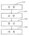
도 1에는 본 발명의 일 실시예에 따른 ITO 잉크의 제조 방법이 도시되어 있다. 도 1을 참조하면, ITO 잉크의 제조 방법은, 혼합 단계(S110)와, 교반 단계(S120)와, 분산 단계(S130)와, 여과 단계(S140)를 포함한다.
1 shows a method for producing ITO ink according to an embodiment of the present invention. Referring to FIG. 1, the method for preparing ITO ink includes a mixing step S110, a stirring step S120, a dispersion step S130, and a filtration step S140.
혼합 단계(S110)에서는 용제에 ITO 분말, 분산제 및 바인더가 혼합되어서 혼합물이 제조된다.In the mixing step (S110), a mixture is prepared by mixing ITO powder, a dispersant and a binder in a solvent.
본 실시예에서는 BTX(Benzene, Toluene, Xylene)계 또는 KETONE계를 주용제로 사용한다. 알코올을 주용제로 사용함에 따라 바인더의 선택이 극히 제한적일 수밖에 없었던 기존의 방법과는 달리, 본 실시예에서는 주용제로 BTX계 또는 KETONE계를 사용하므로 사용가능한 바인더의 종류가 다양해진다.In this embodiment, BTX (Benzene, Toluene, Xylene) type or KETONE type is used as the main solvent. Unlike the conventional method in which the selection of the binder is extremely limited by using alcohol as the main solvent, in the present embodiment, since the BTX system or the KETONE system is used as the main solvent, the types of binders that can be used vary.
본 실시예에서 사용될 수 있는 바인더의 종류는 다양하다. 즉, 폴리에스테르 수지, 폴리우레탄 수지, 폴리아크릴레이트 수지, 석유 수지, 테르펜 수지, 알킬 페놀계, 터펜 페놀계 등이 바인더로서 사용될 수 있으며, 특히, 자외선(UV)를 사용하는 경우에는 바인더로서 우레탄 아크릴레이트 올리고머, 에폭시 아크릴에이트, 다관능성 아크릴레이트 모노머, UV 반응형 모노머 등이 사용될 수 있다. 사용되는 바인더는 용제와의 상용성이 필수적으로 고려된다.There are various kinds of binders that can be used in this embodiment. That is, polyester resins, polyurethane resins, polyacrylate resins, petroleum resins, terpene resins, alkyl phenols, terpene phenols and the like can be used as the binder, in particular, in the case of using UV (UV) as a binder Acrylate oligomers, epoxy acrylates, polyfunctional acrylate monomers, UV reactive monomers and the like can be used. The binder used is considered to be essentially compatible with the solvent.
본 실시예에서는 분산제로서 에스테르계를 사용한다.In this embodiment, an ester system is used as the dispersant.
혼합 단계(S110)에서 UV 경화형일 경우에는 광개시제가 추가로 혼합되며, 무황변계가 사용된다.
In the case of UV curing in the mixing step (S110), the photoinitiator is further mixed, a yellowing-free system is used.
교반 단계(S120)에서는 교반기에 의해 혼합 단계(S110)에 제조된 혼합물이 교반된다.
In the stirring step (S120), the mixture prepared in the mixing step (S110) by the stirrer is stirred.
분산 단계(S130)에서는 교반 단계(S120)에서 교반된 혼합물에 대한 밀링이 이루어져서 ITO 용액이 제조된다. 분산 단계(S130)는 나노 입자를 분산할 수 있는 고속 분산밀이 사용된다.
In the dispersing step (S130), milling is performed on the mixture stirred in the stirring step (S120) to prepare an ITO solution. In the dispersing step (S130), a high-speed dispersion mill capable of dispersing nanoparticles is used.
여과 단계(S140)에서는 분산 단계(S130)에서 제조된 ITO 용액에 대한 필터링이 이루어져서 ITO 잉크가 제조된다.
In the filtration step S140, the ITO ink is manufactured by filtering the ITO solution prepared in the dispersing step S130.
상기와 같은 방법을 통해 제조된 ITO 잉크는 200℃ 내외의 저온에서도 건조가 가능하도록 용제가 선택되었으며, 이 온도에서도 고분자의 증발을 유도할 수 있도록 바인더와 ITO 입자와의 분산을 최대한 작게 하였다. 바인더의 입자는 10nm 이하이고 ITO 입자의 크기는 20 내지 50nm이다. 이러한 ITO 잉크를 필름에 코팅 후 건조하였을 때 저항값은 107 내지 108Ω이다.
The ITO ink prepared by the above method was selected as a solvent to be dried at a low temperature of about 200 ℃, the dispersion of the binder and ITO particles as small as possible to induce evaporation of the polymer even at this temperature. The particles of the binder are 10 nm or less and the size of the ITO particles is 20 to 50 nm. When the ITO ink is coated on a film and dried, the resistance value is 107 to 108 Ω.
도 2에는 본 발명의 일 실시예에 따른 ITO 잉크의 코팅 방법이 도시되어 있다. 도 2를 참조하면, ITO 잉크의 코팅 방법은, ITO 잉크 도포 단계(S210)와, 건조 단계(S220)와, 1차 경화 및 숙성 단계(S230)와, 플라즈마 처리 단계(S240)와, 열처리 단계(S250)를 포함한다.
2 shows a coating method of ITO ink according to an embodiment of the present invention. Referring to Figure 2, the coating method of the ITO ink, ITO ink coating step (S210), drying step (S220), primary curing and aging step (S230), plasma treatment step (S240), heat treatment step (S250).
ITO 잉크 도포 단계(S210)에서는 피착재에 ITO 잉크가 도포된다. ITO 잉크 도포 단계(S100)에서 사용되는 ITO 잉크는 도 1에 도시된 ITO 잉크의 제조 방법으로 제조된 ITO 잉크가 사용될 수 있다. 피착재로는 글래스 또는 내열 필름이 사용될 수 있다. ITO 잉크 도포 단계(S210)에서 ITO 잉크는 500nm 내지 1.0㎛의 두께로 코팅된다.In ITO ink application step (S210), ITO ink is applied to the adherend. As the ITO ink used in the ITO ink applying step S100, ITO ink prepared by the method for producing ITO ink shown in FIG. 1 may be used. Glass or heat resistant film may be used as the adherend. In the ITO ink application step (S210), the ITO ink is coated with a thickness of 500 nm to 1.0 μm.
ITO 잉크가 글래스에 코팅되는 경우에 본 실시예에서는 ITO 잉크의 점도는 50cps 이하인 것으로 하고, 코팅은 스핀 코터에서 실시되었다.In the case where ITO ink is coated on the glass, the viscosity of the ITO ink is assumed to be 50 cps or less in this embodiment, and the coating was carried out in a spin coater.
ITO 잉크가 내열 필름에 코팅되는 경우에 본 실시예에서는 ITO 잉크의 점도는 300cps 이하인 것으로 하고, 코팅은 리버스롤 키스 코팅법이 사용되었다. 리버스롤 키스 코팅벙은 코팅롤의 접촉각을 최소화하기 위하여 코팅롤의 반경을 소형화하여 롤 표면과 가공 원단의 도료 볼텍스(vortex) 범위를 극소화함으로써 박막의 균일한 도료를 코팅하게 된다. 그러나 실험실에서 작업을 할 경우 바코타 등으로 일정 크기의 필름을 코팅하고 원하는 크기로 절단한다.
When the ITO ink is coated on the heat resistant film, in this embodiment, the viscosity of the ITO ink is 300 cps or less, and the reverse roll kiss coating method is used for the coating. Reverse roll kiss coating reduces the radius of the coating roll to minimize the contact angle of the coating roll to minimize the paint vortex range of the roll surface and the processed fabric to coat the uniform coating of the thin film. However, when working in the laboratory, a certain size of the film is coated with a bakota and cut to the desired size.
건조 단계(S220)에서는 ITO 잉크 도포 단계(S210)를 거친 피착재가 일차 건조된다. 건조 단계(S220)는 100℃ 내외에서 이루어진다.
In the drying step (S220), the adherend that passed through the ITO ink application step (S210) is first dried. Drying step (S220) is made in about 100 ℃.
1차 경화 및 숙성 단계(S230)에서는 건조 단계(S220)를 거친 피착재에 대한 열처리가 이루어져서 도포된 ITO 잉크가 1차 경화 및 숙성된다. 제1 열처리 단계(S230)는 190℃ 내지 210℃에서 25분 내지 35분간 이루어진다.
In the primary curing and aging step (S230), heat treatment is performed on the adherend that passed through the drying step (S220), and the applied ITO ink is first cured and aged. The first heat treatment step (S230) is made from 190 to 210 ℃ 25 minutes to 35 minutes.
플라즈마 처리 단계(S240)에서는 1차 경화 및 숙성 단계(S230)를 거친 피착재에 대한 플라즈마 열처리가 이루어진다. 플라즈마 열처리는 피착재를 열플라즈마를 발생시킬 수 있는 소형 열플라즈마 발생 장치 안에 넣고 5분 내지 60분간 방치함으로써 수행된다. 이때 사용되는 소형 열플라즈마 발생 장치의 용량은 1kw의 전원장치에 사이즈는 가로*세로*높이=90*100*90 정도의 규격이다. 플라즈마 열처리에 의해 코팅 표면은 순식간에 급속도로 온도가 상승하면서 열플라즈마 장치에 의해 발생하는 반응성이 매우 큰 산소 라디칼 등이 나노 입자를 둘러싸고 있는 유기 고분자 보호막과 반응하여 유기물을 분해하여 날려버리게 된다. 이때, 유기물질은 입자가 매우 작고 상대적으로 비표면적은 매우 커서 에너지를 충분히 흡수하여 산소 라디칼에 의해 낮은 온도에서도 분해되며, 표면의 5 내지 50nm 정도의 두께까지만 분해한다.
In the plasma treatment step (S240), plasma heat treatment is performed on the adherend that has undergone the primary curing and aging step (S230). Plasma heat treatment is performed by placing the adherend in a small thermal plasma generating apparatus capable of generating thermal plasma and standing for 5 to 60 minutes. At this time, the capacity of the small thermal plasma generator used is 1kw power supply, the size of width * length * height = 90 * 100 * 90 standard. By plasma heat treatment, the coating surface rapidly rises in temperature, and oxygen radicals, such as highly reactive oxygen radicals generated by the thermal plasma device, react with the organic polymer protective film surrounding the nanoparticles and decompose and blow off the organic material. At this time, the organic material is very small particles and relatively large specific surface area absorbs energy enough to be decomposed at low temperature by oxygen radicals, only to a thickness of about 5 to 50nm surface.
열처리 단계(S250)에서는 플라즈마 처리 단계(S240)를 거친 피착재에 대한 열처리가 수행된다. 열처리 단계(S250)는 드라이 오븐에서 200 내지 230℃의 온도로 1시간 내지 4시간 동안 방치됨으로써 수행된다. 구체적인 열처리 시간은 사용된 바인더나 용제의 종류 및 도포량에 따라 적절히 조절될 수 있다. 열처리 단계(S250)를 거친 ITO 잉크의 저항값은 104Ω이 된다. 이때, 본 실시예에서는 그 만드는 입자의 크기를 5nm 내외까지 고분자와 ITO 입자를 분산하면 저항값은 수백Ω 내외로 떨어지게 된다. 이렇게 하면 글래스나 필름의 표면에 인쇄를 함으로써 소저의 절차를 거쳐서 수백Ω 내외의 투명 전극을 얻을 수 있게 된다.
In the heat treatment step S250, heat treatment is performed on the adherend that has undergone the plasma treatment step S240. The heat treatment step (S250) is performed by leaving for 1 hour to 4 hours at a temperature of 200 to 230 ℃ in a dry oven. Specific heat treatment time may be appropriately adjusted according to the type and amount of the binder or solvent used. The resistance value of the ITO ink having undergone the heat treatment step S250 is 104 Ω. At this time, in the present embodiment, when the polymer and the ITO particles are dispersed up to about 5 nm in size, the resistance drops to around several hundred Ω. In this way, by printing on the surface of glass or film, a transparent electrode of several hundred Ω can be obtained through the procedure of leveling.
상기 실시예에서 가해지는 열은 모두 200℃ 내외로서 피착물이 필름인 경우에도 필름의 변형 온도보다 낮기 때문에, 필름 타입의 투명 전극을 제조에 유용하게 된다.
Since the heat applied in the above embodiment is all about 200 ° C. and lower than the deformation temperature of the film even when the adherend is a film, the film-type transparent electrode is useful for manufacturing.
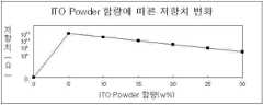
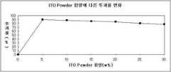
아래 표 1은 분산매로 톨루엔(toluene)을 사용하여 고형분 함량과 분산제 함량에 따른 저항값 비교와 투과율 및 분산안정성에 대한 테스트 데이터를 보여준다(LH-1000, 1000rpm, 205℃ 1시간).Table 1 below shows toluene (toluene) as a dispersion medium to compare the resistance value according to the solid content and the dispersant content, and test data for the transmittance and dispersion stability (LH-1000, 1000rpm, 205 ℃ 1 hour).
(w%)ITO powder
(w%)
(Phosphonic acid ester)(w%)TANEMUL AP
(Phosphonic acid ester) (w%)
(w%)toluene
(w%)
-polyesterbinder (w%)
-polyester
안정성
(기간)Dispersion
stability
(term)
1-1Example
1-1
1-2Example
1-2
1-3Example
1-3
1-4Example
1-4
1-5Example
1-5
1-6Example
1-6
표 1의 데이터를 살펴보면 알코올 베이스와 마찬가지로 고형분 함량이 높아질수록 측정 저항치가 낮아졌으며 투과율은 떨어짐을 알 수 있다. 분산안정성의 경우도 상기 결과로 알 수 있듯이 함량이 높아질수록 떨어짐을 알 수 있다. 다만 저항값의 경우 알코올 베이스에 비해 떨어짐을 알 수 있는데 이것은 분산매가 톨루엔이어서라기보다 분산매를 바꾼 후 들어가는 분산제 양이 상대적으로 더 많아져서 저항치가 비교적 높게 나온 것으로 예상된다. 상기 표 1의 데이터와 관련된 그래프가 도 3 내지 도 5에 도시되어 있다.
Looking at the data in Table 1, it can be seen that, as with the alcohol base, the higher the solid content, the lower the measurement resistance and the lower the transmittance. As can be seen from the above result of dispersion stability, the higher the content, the lower it can be seen. However, the resistance value is lower than the alcohol base, which is expected to be relatively high because the amount of dispersant added after changing the dispersion medium is relatively higher than that of the toluene. Graphs relating to the data in Table 1 above are shown in FIGS.
아래 표 2는 분산매로 톨루엔을 사용하고 바인더로 2-HEMA를 사용하여 UV로 경화하는 예에 대한 테스트 데이터이다(LH-1000, 1000rpm, 205℃ 1시간, UV 조사량 1000mJ/cm2).Table 2 below is test data for an example of curing with UV using toluene as a dispersion medium and 2-HEMA as a binder (LH-1000, 1000 rpm, 205 ° C. 1 hour, UV irradiation amount 1000 mJ / cm2 ).
(w%)ITO powder
(w%)
(Phosphonic acid ester)(w%)TANEMUL AP
(Phosphonic acid ester) (w%)
(w%)toluene
(w%)
(184)Photoinitiator
(184)
2-1Example
2-1
(경화과도)offshoot
(Hardening degree)
2-2Example
2-2
(경화과도)offshoot
(Hardening degree)
2-3Example
2-3
2-4Example
2-4
(경화부족)exfoliation
(Lack of hardening)
2-5Example
2-5
(경화부족)exfoliation
(Lack of hardening)
표 2의 테스트 결과상 비교적 양호한 저항값을 보인 배합 비율로 테스트를 진행했다. 결과를 살펴보면 바인더로 사용한 2-HEMA의 함량에 의해 경화도가 결정됨으로써 저항값이 변경되고 기재 접착력이 달라짐을 알 수 있다. 표 2의 데이터와 관계된 그래프가 도 6에 도시되어 있다.
The test was conducted at a blending ratio showing a relatively good resistance value according to the test results in Table 2. Looking at the results, it can be seen that since the degree of curing is determined by the content of 2-HEMA used as the binder, the resistance value is changed and the substrate adhesion strength is changed. A graph relating to the data in Table 2 is shown in FIG.
표 3은 분산제 및 바인더로 레진(RESIN)을 사용하고 함량에 따른 저항값 및 기재접착성, 분산안정성에 대한 테스트 테이터를 보여준다(LH-1000, 1000rpm, 205℃ 1시간).Table 3 shows resins (RESIN) as dispersants and binders, and shows test data for resistivity, substrate adhesion, and dispersion stability according to content (LH-1000, 1000 rpm, 205 ° C. for 1 hour).
(w%)ITO powder
(w%)
(GUM ROSIN)RESIN (w%)
(GUM ROSIN)
(w%)toluene
(w%)
(Ω)Resistance
(Ω)
안정성
(기간)Dispersion
stability
(term)
3-1Example
3-1
3-2Example
3-2
3-3Example
3-3
3-4Example
3-4
3-5Example
3-5
3-6Example
3-6
테스트 결과상 레진의 함량이 높을수록 분산안정성이 좋아지고 저항값이 높아진다. 레진을 첨가함으로 고형분이 높아져서 점도가 상승하여 분산안전성이 높은 것으로 보이며, 반대로 레진의 함량이 높을수록 저항을 높이는 역할을 함으로써 저항값이 상승하는 원인으로 보인다. 기재접착성은 전반적으로 약하게 나타나는데 연화점이 높은 레진을 사용하면 부착력이 약간 상승하는 결과가 도출된다. 도 3의 데이터와 관계된 그래프가 도 7에 도시되어 있다.
The higher the resin content, the better the dispersion stability and the higher the resistance. By adding the resin, the solid content increases, the viscosity increases, and the dispersion safety seems to be high. On the contrary, the higher the content of the resin, the higher the resistance. Substrate adhesiveness is generally weak. Using a resin having a high softening point results in a slight increase in adhesion. A graph relating to the data of FIG. 3 is shown in FIG. 7.
이상 실시예를 들어 본 발명을 설명하였으나, 본 발명은 이에 제한되는 것은 아니다. 상기 실시예는 본 발명의 취지 및 범위를 벗어나지 않고 수정되거나 변경될 수 있으며, 당업자는 이러한 수정과 변경도 본 발명에 속하는 것임을 알 수 있을 것이다.Although the present invention has been described with reference to the above embodiments, the present invention is not limited thereto. It will be understood by those skilled in the art that the foregoing embodiments are susceptible to modifications and variations that do not depart from the spirit and scope of the invention.
S110 : 혼합 단계 S120 : 교반 단계
S130 : 분산 단계 S140 : 여과 단계
S210 : ITO 잉크 도포 단계 S220 : 건조 단계
S230 : 1차 경화 및 숙성 단계 S240 : 플라즈마 처리 단계
S250 : 열처리 단계S110 mixing step S120 stirring step
S130: dispersing step S140: filtration step
S210: ITO Ink Coating Step S220: Drying Step
S230: first curing and aging step S240: plasma treatment step
S250: heat treatment step
Claims (9)
Translated fromKorean상기 ITO 잉크가 도포된 피착재를 열플라즈마를 이용하여 상기 ITO 입자를 둘러싸고 있는 유기물의 적어도 일부를 분해시키는 플라즈마 처리 단계; 및
상기 플라즈마 처리 단계를 거친 피착재에 대한 열처리를 수행하는 열처리 단계를 포함하는 것을 특징으로 하는 ITO 잉크의 코팅 방법.An ITO ink applying step of applying the ITO ink to the adherend;
A plasma treatment step of decomposing at least a portion of the organic material surrounding the ITO particles by using a thermal plasma on the adherend coated with the ITO ink; And
And a heat treatment step of performing heat treatment on the adherend after the plasma treatment step.
상기 열처리 단계는 200 내지 230℃의 온도에서 1시간 내지 4시간 동안 수행되는 것을 특징으로 하는 ITO 잉크의 코팅 방법.The method according to claim 5,
The heat treatment step is a coating method of the ITO ink, characterized in that performed for 1 hour to 4 hours at a temperature of 200 to 230 ℃.
상기 플라즈마 처리 단계 전에 상기 피착재를 경화시키고 숙성시키는 1차 경화 및 숙성 단계를 더 포함하며,
상기 1차 경화 및 숙성 단계는 190℃ 내지 210℃에서 25분 내지 35분간 수행되는 것을 특징으로 하는 ITO 잉크의 코팅 방법.The method according to claim 5,
Further comprising a primary curing and aging step of curing and maturing the adherend prior to the plasma treatment step,
The first curing and aging step is a coating method of the ITO ink, characterized in that performed for 25 to 35 minutes at 190 ℃ to 210 ℃.
상기 피착재는 필름인 것을 특징으로 하는 ITO 잉크의 코팅 방법.The method according to claim 5,
The coating material is an ITO ink coating method, characterized in that the film.
Priority Applications (1)
| Application Number | Priority Date | Filing Date | Title |
|---|---|---|---|
| KR1020120043901AKR101330065B1 (en) | 2011-04-27 | 2012-04-26 | Method for fabricating and coating ito ink |
Applications Claiming Priority (3)
| Application Number | Priority Date | Filing Date | Title |
|---|---|---|---|
| KR20110039852 | 2011-04-27 | ||
| KR1020110039852 | 2011-04-27 | ||
| KR1020120043901AKR101330065B1 (en) | 2011-04-27 | 2012-04-26 | Method for fabricating and coating ito ink |
Publications (2)
| Publication Number | Publication Date |
|---|---|
| KR20120121855A KR20120121855A (en) | 2012-11-06 |
| KR101330065B1true KR101330065B1 (en) | 2013-11-14 |
Family
ID=47508250
Family Applications (1)
| Application Number | Title | Priority Date | Filing Date |
|---|---|---|---|
| KR1020120043901AActiveKR101330065B1 (en) | 2011-04-27 | 2012-04-26 | Method for fabricating and coating ito ink |
Country Status (1)
| Country | Link |
|---|---|
| KR (1) | KR101330065B1 (en) |
Families Citing this family (1)
| Publication number | Priority date | Publication date | Assignee | Title |
|---|---|---|---|---|
| KR102099983B1 (en)* | 2013-05-31 | 2020-04-10 | 한양대학교 산학협력단 | Preparation method of ITO pellet and ITO pellet using the same |
Citations (4)
| Publication number | Priority date | Publication date | Assignee | Title |
|---|---|---|---|---|
| JPH09278487A (en)* | 1996-04-10 | 1997-10-28 | Seiko Epson Corp | Method for producing conductive particles, method for producing color filter using the same, color filter using the same, display panel and electronic device |
| KR20060034392A (en)* | 2004-10-19 | 2006-04-24 | 에스엔티 주식회사 | Coating method of resin material and resin material coated with conductive particles or ferromagnetic particles manufactured using the same |
| JP2008218243A (en)* | 2007-03-05 | 2008-09-18 | Dainippon Printing Co Ltd | Transparent conductive substrate manufacturing method and transparent conductive substrate |
| JP2009138142A (en)* | 2007-12-07 | 2009-06-25 | Mitsui Mining & Smelting Co Ltd | Ito ink |
- 2012
- 2012-04-26KRKR1020120043901Apatent/KR101330065B1/enactiveActive
Patent Citations (4)
| Publication number | Priority date | Publication date | Assignee | Title |
|---|---|---|---|---|
| JPH09278487A (en)* | 1996-04-10 | 1997-10-28 | Seiko Epson Corp | Method for producing conductive particles, method for producing color filter using the same, color filter using the same, display panel and electronic device |
| KR20060034392A (en)* | 2004-10-19 | 2006-04-24 | 에스엔티 주식회사 | Coating method of resin material and resin material coated with conductive particles or ferromagnetic particles manufactured using the same |
| JP2008218243A (en)* | 2007-03-05 | 2008-09-18 | Dainippon Printing Co Ltd | Transparent conductive substrate manufacturing method and transparent conductive substrate |
| JP2009138142A (en)* | 2007-12-07 | 2009-06-25 | Mitsui Mining & Smelting Co Ltd | Ito ink |
Also Published As
| Publication number | Publication date |
|---|---|
| KR20120121855A (en) | 2012-11-06 |
Similar Documents
| Publication | Publication Date | Title |
|---|---|---|
| KR950014928B1 (en) | Transparent conductive substrate and manufacturing method thereof | |
| EP2154598B1 (en) | Transparent conductive polycarbonate film coated with carbon nanotubes and touch panel using the same | |
| JP5256459B2 (en) | Transparent conductive film and method for producing the same | |
| EP1993106A1 (en) | Method of manufacturing transparent conductive film containing carbon nanotubes and binder, and transparent conductive film manufactured thereby | |
| EP2178095B1 (en) | Transparent electroconductive thin film and process for producing the transparent electroconductive thin film | |
| CN100385573C (en) | A special silver paste for indium tin oxide and its manufacturing method | |
| KR101485858B1 (en) | Method of patterning a transparent electrode metal nanowires and a transparent electrode patterned metal nanowires thereby | |
| KR20130062176A (en) | Substrate films for transparent electrode films | |
| KR101356260B1 (en) | Preparing method of Electrode substrate | |
| JP6866104B2 (en) | Conductors, their manufacturing methods, and devices containing them | |
| KR20090021189A (en) | Transparent conductive film forming composition, transparent conductive film and display | |
| CN107615408B (en) | Manufacturing method of conductive film and conductive film | |
| KR101330065B1 (en) | Method for fabricating and coating ito ink | |
| EP3766943A1 (en) | Coating composition, electroconductive film, and liquid crystal display panel | |
| JP6559509B2 (en) | Antimony-doped tin oxide conductive film forming composition and antimony-doped tin oxide conductive film | |
| KR101321097B1 (en) | Carbon nano tube transparent electrode, method for manufacturing the same, and coating composition for carbon nano tube transparent electrode | |
| CN113764137A (en) | Preparation method of nano silver wire conductive film, nano silver wire conductive film and application thereof | |
| JP2008034345A (en) | Conductive oxide fine particle dispersion, transparent conductive film forming coating liquid, and transparent conductive film | |
| CN115394475A (en) | Large-size transparent flexible silver nanowire film heater and preparation method thereof | |
| CN113773545A (en) | A fully flexible and printable electrode preparation method | |
| KR101535208B1 (en) | Transparent conductive film having metal nano-wire structure | |
| JP4958144B2 (en) | Composition for forming transparent conductive film, transparent conductive film and display | |
| JP4958143B2 (en) | Composition for forming transparent conductive film, transparent conductive film and display | |
| CN110172293A (en) | A kind of UV solidification transparent conductive coating and preparation method thereof | |
| JP3190416B2 (en) | Method for manufacturing transparent conductive substrate |
Legal Events
| Date | Code | Title | Description |
|---|---|---|---|
| A201 | Request for examination | ||
| PA0109 | Patent application | Patent event code:PA01091R01D Comment text:Patent Application Patent event date:20120426 | |
| PA0201 | Request for examination | ||
| PG1501 | Laying open of application | ||
| E902 | Notification of reason for refusal | ||
| PE0902 | Notice of grounds for rejection | Comment text:Notification of reason for refusal Patent event date:20130830 Patent event code:PE09021S01D | |
| E701 | Decision to grant or registration of patent right | ||
| PE0701 | Decision of registration | Patent event code:PE07011S01D Comment text:Decision to Grant Registration Patent event date:20131031 | |
| GRNT | Written decision to grant | ||
| PR0701 | Registration of establishment | Comment text:Registration of Establishment Patent event date:20131107 Patent event code:PR07011E01D | |
| PR1002 | Payment of registration fee | Payment date:20131107 End annual number:3 Start annual number:1 | |
| PG1601 | Publication of registration | ||
| FPAY | Annual fee payment | Payment date:20161017 Year of fee payment:4 | |
| PR1001 | Payment of annual fee | Payment date:20161017 Start annual number:4 End annual number:4 | |
| FPAY | Annual fee payment | Payment date:20181105 Year of fee payment:6 | |
| PR1001 | Payment of annual fee | Payment date:20181105 Start annual number:6 End annual number:6 | |
| FPAY | Annual fee payment | Payment date:20191106 Year of fee payment:7 | |
| PR1001 | Payment of annual fee | Payment date:20191106 Start annual number:7 End annual number:7 | |
| PR1001 | Payment of annual fee | Payment date:20201020 Start annual number:8 End annual number:8 | |
| PR1001 | Payment of annual fee | Payment date:20211026 Start annual number:9 End annual number:9 | |
| PR1001 | Payment of annual fee | Payment date:20221021 Start annual number:10 End annual number:10 | |
| PR1001 | Payment of annual fee | Payment date:20230925 Start annual number:11 End annual number:11 |