KR101329510B1 - An apparatus and method for assisting parking - Google Patents
An apparatus and method for assisting parkingDownload PDFInfo
- Publication number
- KR101329510B1 KR101329510B1KR1020110102559AKR20110102559AKR101329510B1KR 101329510 B1KR101329510 B1KR 101329510B1KR 1020110102559 AKR1020110102559 AKR 1020110102559AKR 20110102559 AKR20110102559 AKR 20110102559AKR 101329510 B1KR101329510 B1KR 101329510B1
- Authority
- KR
- South Korea
- Prior art keywords
- vehicle
- driving trajectory
- parking
- steering angle
- expected
- Prior art date
- Legal status (The legal status is an assumption and is not a legal conclusion. Google has not performed a legal analysis and makes no representation as to the accuracy of the status listed.)
- Active
Links
Images


Classifications
- B—PERFORMING OPERATIONS; TRANSPORTING
- B60—VEHICLES IN GENERAL
- B60R—VEHICLES, VEHICLE FITTINGS, OR VEHICLE PARTS, NOT OTHERWISE PROVIDED FOR
- B60R1/00—Optical viewing arrangements; Real-time viewing arrangements for drivers or passengers using optical image capturing systems, e.g. cameras or video systems specially adapted for use in or on vehicles
- B60R1/20—Real-time viewing arrangements for drivers or passengers using optical image capturing systems, e.g. cameras or video systems specially adapted for use in or on vehicles
- B60R1/22—Real-time viewing arrangements for drivers or passengers using optical image capturing systems, e.g. cameras or video systems specially adapted for use in or on vehicles for viewing an area outside the vehicle, e.g. the exterior of the vehicle
- B60R1/23—Real-time viewing arrangements for drivers or passengers using optical image capturing systems, e.g. cameras or video systems specially adapted for use in or on vehicles for viewing an area outside the vehicle, e.g. the exterior of the vehicle with a predetermined field of view
- B—PERFORMING OPERATIONS; TRANSPORTING
- B60—VEHICLES IN GENERAL
- B60W—CONJOINT CONTROL OF VEHICLE SUB-UNITS OF DIFFERENT TYPE OR DIFFERENT FUNCTION; CONTROL SYSTEMS SPECIALLY ADAPTED FOR HYBRID VEHICLES; ROAD VEHICLE DRIVE CONTROL SYSTEMS FOR PURPOSES NOT RELATED TO THE CONTROL OF A PARTICULAR SUB-UNIT
- B60W30/00—Purposes of road vehicle drive control systems not related to the control of a particular sub-unit, e.g. of systems using conjoint control of vehicle sub-units
- B60W30/06—Automatic manoeuvring for parking
- B—PERFORMING OPERATIONS; TRANSPORTING
- B60—VEHICLES IN GENERAL
- B60R—VEHICLES, VEHICLE FITTINGS, OR VEHICLE PARTS, NOT OTHERWISE PROVIDED FOR
- B60R1/00—Optical viewing arrangements; Real-time viewing arrangements for drivers or passengers using optical image capturing systems, e.g. cameras or video systems specially adapted for use in or on vehicles
- B60R1/02—Rear-view mirror arrangements
- B60R1/08—Rear-view mirror arrangements involving special optical features, e.g. avoiding blind spots, e.g. convex mirrors; Side-by-side associations of rear-view and other mirrors
- B—PERFORMING OPERATIONS; TRANSPORTING
- B62—LAND VEHICLES FOR TRAVELLING OTHERWISE THAN ON RAILS
- B62D—MOTOR VEHICLES; TRAILERS
- B62D15/00—Steering not otherwise provided for
- B62D15/02—Steering position indicators ; Steering position determination; Steering aids
- B62D15/029—Steering assistants using warnings or proposing actions to the driver without influencing the steering system
- B62D15/0295—Steering assistants using warnings or proposing actions to the driver without influencing the steering system by overlaying a vehicle path based on present steering angle over an image without processing that image
- G—PHYSICS
- G08—SIGNALLING
- G08G—TRAFFIC CONTROL SYSTEMS
- G08G1/00—Traffic control systems for road vehicles
- G08G1/16—Anti-collision systems
- G08G1/168—Driving aids for parking, e.g. acoustic or visual feedback on parking space
- H—ELECTRICITY
- H04—ELECTRIC COMMUNICATION TECHNIQUE
- H04N—PICTORIAL COMMUNICATION, e.g. TELEVISION
- H04N7/00—Television systems
- H04N7/18—Closed-circuit television [CCTV] systems, i.e. systems in which the video signal is not broadcast
- H04N7/181—Closed-circuit television [CCTV] systems, i.e. systems in which the video signal is not broadcast for receiving images from a plurality of remote sources
- B—PERFORMING OPERATIONS; TRANSPORTING
- B60—VEHICLES IN GENERAL
- B60R—VEHICLES, VEHICLE FITTINGS, OR VEHICLE PARTS, NOT OTHERWISE PROVIDED FOR
- B60R2300/00—Details of viewing arrangements using cameras and displays, specially adapted for use in a vehicle
- B60R2300/30—Details of viewing arrangements using cameras and displays, specially adapted for use in a vehicle characterised by the type of image processing
- B60R2300/304—Details of viewing arrangements using cameras and displays, specially adapted for use in a vehicle characterised by the type of image processing using merged images, e.g. merging camera image with stored images
- B60R2300/305—Details of viewing arrangements using cameras and displays, specially adapted for use in a vehicle characterised by the type of image processing using merged images, e.g. merging camera image with stored images merging camera image with lines or icons
- B—PERFORMING OPERATIONS; TRANSPORTING
- B60—VEHICLES IN GENERAL
- B60R—VEHICLES, VEHICLE FITTINGS, OR VEHICLE PARTS, NOT OTHERWISE PROVIDED FOR
- B60R2300/00—Details of viewing arrangements using cameras and displays, specially adapted for use in a vehicle
- B60R2300/80—Details of viewing arrangements using cameras and displays, specially adapted for use in a vehicle characterised by the intended use of the viewing arrangement
- B60R2300/806—Details of viewing arrangements using cameras and displays, specially adapted for use in a vehicle characterised by the intended use of the viewing arrangement for aiding parking
Landscapes
- Engineering & Computer Science (AREA)
- Multimedia (AREA)
- Mechanical Engineering (AREA)
- Transportation (AREA)
- Chemical & Material Sciences (AREA)
- Combustion & Propulsion (AREA)
- Signal Processing (AREA)
- Physics & Mathematics (AREA)
- General Physics & Mathematics (AREA)
- Automation & Control Theory (AREA)
- Traffic Control Systems (AREA)
- Closed-Circuit Television Systems (AREA)
Abstract
Translated fromKoreanDescription
Translated fromKorean본 발명은 주차를 보조하는 장치 및 방법에 관한 것으로서, 더욱 상세하게는 차량의 후방 카메라 및 거리 측정 센서를 이용하여 주차를 보조할 수 있는 장치 및 방법에 관한 것이다.
The present invention relates to an apparatus and method for assisting parking, and more particularly, to an apparatus and method for assisting parking using a rear camera and a distance measuring sensor of a vehicle.
최근들어 자동차의 동력 성능에 대한 소비자 만족뿐만 아니라 소비자의 편의를 위한 장치가 많이 보급되고 있다. 그러한 예로써 주차 보조를 위한 전/후방 카메라와 자동차의 상태를 한눈에 파악할 수 있는 통합 디스플레이 장치의 보급이 보편화되고 있는 추세다. 운전자는 전방 또는 후방 주차시에 차량의 전/후방에 구비된 거리 측정 센서와 디스플레이 장치를 통해 차량 주변의 장애물을 볼 수 있고, 장애물까지의 거리를 알 수 있다.Recently, devices for convenience of consumers as well as consumer satisfaction with power performance of automobiles have been widely used. For example, the spread of the front and rear cameras for parking assistance and the integrated display device that can grasp the state of the car at a glance is becoming more common. The driver can see obstacles around the vehicle through the distance measuring sensor and the display device provided at the front and rear of the vehicle at the front or rear parking, and can know the distance to the obstacle.
종래에는 주차시의 이러한 장애물 인식을 위해 단순히 전방 또는 후방 장면을 표시하거나 또는 단순한 거리 표시만을 제공하는, 제한적인 정보를 제공하고 있다. 이에 따라, 종래의 기술에 비해 더 직관적이고 사용자 만족도를 높일 수 있는 주차 보조를 위한 디스플레이 장치 및 방법이 필요하다.
Conventionally, limited information is provided for simply displaying a front or rear scene or providing only a distance display for recognizing the obstacle when parking. Accordingly, there is a need for a display device and method for parking assistance that can be more intuitive and increase user satisfaction compared to the prior art.
본 발명은 직관적이고 사용자 만족도를 높일 수 있는 주차 보조를 위한 표시 장치 및 방법을 제공하고자 한다.
The present invention is to provide a display device and method for parking assistance that can be intuitive and increase the user satisfaction.
본 발명의 일 실시예에 따른 주차 보조 장치는 차량의 전방 또는 후방의 영상을 촬영하는 이미지 센서; 및 상기 차량의 조향각 정보를 이용하여 주차목표영역까지의 예상 주행 궤적을 생성하고, 상기 촬영된 차량의 전방 또는 후방의 영상에 상기 예상 주행 궤적을 오버레이(overlay)하는 예상 주행 궤적 생성 및 처리부를 포함할 수 있다.Parking assistance apparatus according to an embodiment of the present invention comprises an image sensor for taking an image of the front or rear of the vehicle; And an expected driving trajectory generation and processing unit for generating an expected driving trajectory to the parking target area by using the steering angle information of the vehicle and overlaying the expected driving trajectory on an image of the front or rear of the photographed vehicle. can do.
상기 예상 주행 궤적은 상기 차량의 후륜에 따른 제1 예상 주행 궤적과 상기 차량의 전륜에 따른 제2 예상 주행 궤적을 포함할 수 있다.The anticipated driving trajectory may include a first anticipated driving trajectory along the rear wheel of the vehicle and a second anticipated driving trajectory along the front wheel of the vehicle.
상기 주차 보조 장치는 상기 오버레이된 상기 차량의 전방 또는 후방의 영상 및 상기 예상 주행 궤적을 함께 표시하는 디스플레이부를 더 포함할 수 있다.The parking assist device may further include a display unit displaying both the front and rear images of the overlaid vehicle and the expected driving trajectory together.
또한, 상기 제1 예상 주행 궤적 및 상기 제2 예상 주행 궤적은 상기 차량의 스티어링 휠의 조향각에 따라 실시간으로 업데이트될 수 있다.The first expected driving trajectory and the second expected driving trajectory may be updated in real time according to the steering angle of the steering wheel of the vehicle.
본 발명의 일 실시예에 따른 주차 보조를 위한 방법은 상기 차량의 전방 또는 후방 영상을 획득하는 단계; 상기 차량의 조향각 정보에 따라 상기 차량의 예상 주행 궤적을 생성하는 단계; 상기 차량의 예상 주행 궤적을 상기 차량의 전방 또는 후방 영상에 오버레이하는 단계; 및 상기 오버레이된 상기 차량의 전방 또는 후방 영상 및 상기 차량의 예상 주행 궤적을 함께 디스플레이하는 단계를 포함할 수 있다.According to an aspect of the present invention, there is provided a method for assisting parking, including: obtaining a front or rear image of the vehicle; Generating an expected driving trajectory of the vehicle according to the steering angle information of the vehicle; Overlaying an expected driving trajectory of the vehicle on a front or rear image of the vehicle; And displaying the front or rear image of the overlaid vehicle and the expected driving trajectory of the vehicle together.
또한, 상기 차량의 예상 주행 궤적은 상기 차량의 후륜에 따른 제1 예상 주행 궤적과 상기 차량의 전륜에 따른 제2 예상 주행 궤적을 포함할 수 있고, 상기 제1 예상 주행 궤적 및 상기 제2 예상 주행 궤적은 상기 차량의 스티어링 휠의 조향각에 따라 실시간으로 업데이트될 수 있다.
The predicted driving trajectory of the vehicle may include a first predicted driving trajectory according to the rear wheel of the vehicle and a second predicted driving trajectory according to the front wheel of the vehicle, and the first predicted driving trajectory and the second predicted driving trajectory. The trajectory may be updated in real time according to the steering angle of the steering wheel of the vehicle.
차량의 주차를 보조하기 위해, 종래 기술은 차량의 후륜의 궤적을 기준으로 차량의 예상 주행 궤적을 표시하였다. 이러한 경우 실제 차량이 진행하는 영역을 충분히 표시하지 않아 예상 주행 궤적 상에 있지 아니하는 장애물과의 충돌이 발생하여 운전자에게 예상치 못한 손해를 입히는 경우가 많다. 이를 해소하기 위하여 차량의 후륜은 물론 전륜의 예상 주행 궤적을 포함한 예상 주행 궤적을 함께 표시하여 표시된 예상 주행 궤적 상의 장애물을 인지하고 용이하게 피할 수 있다.
In order to assist the parking of the vehicle, the prior art has indicated the expected driving trajectory of the vehicle based on the trajectory of the rear wheel of the vehicle. In this case, the actual vehicle does not sufficiently display the area, the collision with the obstacle that is not on the expected driving trajectory often causes unexpected damage to the driver. In order to solve this problem, it is possible to recognize and easily avoid obstacles on the displayed predicted driving trajectory by displaying the predicted driving trajectory including the expected driving trajectory of the front wheel as well as the front wheel of the vehicle.
도 1은 본 발명의 일 실시예에 따른 주차 보조 장치의 블록도를 도시한다.
도 2는 본 발명의 일 실시예에 따른 조향각에 다른 차량의 궤적을 계산하기 위한 방법을 설명하는 개념도를 도시한다.
도 3은 본 발명의 일 실시예에 따른 주차 보조 장치 및 방법의 차량의 예상 주행 궤적을 도시한다.
도 4는 종래 기술에 따른 주차 보조 장치 및 방법의 디스플레이 장면을 도시한다.
도 5는 본 발명의 일 실시예에 따른 주차 보조 장치 및 방법의 디스플레이 장면을 도시한다.
도 6은 본 발명의 일 실시예에 따른 주차 보조 방법의 흐름도를 도시한다.1 is a block diagram of a parking assistance apparatus according to an embodiment of the present invention.
2 is a conceptual diagram illustrating a method for calculating a trajectory of a vehicle different from a steering angle according to an embodiment of the present invention.
3 illustrates an expected driving trajectory of the vehicle of the parking assisting apparatus and method according to an embodiment of the present invention.
4 shows a display scene of a parking assist device and method according to the prior art.
5 shows a display scene of the parking assisting apparatus and method according to an embodiment of the present invention.
6 is a flowchart illustrating a parking assisting method according to an embodiment of the present invention.
본 명세서 및 청구범위에 사용된 용어나 단어는 통상적이거나 사전적인 의미로 한정해서 해석되어서는 아니되며, 본 발명의 기술적 사상에 부합하는 의미와 개념으로 해석되어야만 한다. 따라서, 본 명세서에 기재된 실시예와 도면에 도시된 구성은 본 발명의 가장 바람직한 일 실시예에 불과할 뿐이고 본 발명의 기술적 사상을 모두 포괄하는 것은 아니므로, 본 출원시점에 있어서 이들을 대체할 수 있는 다양한 균등물과 변형예들이 있을 수 있음을 이해하여야 한다.The terms and words used in the present specification and claims should not be construed as limited to ordinary or dictionary terms and should be construed in a sense and concept consistent with the technical idea of the present invention. Therefore, the embodiments described in the present specification and the configurations shown in the drawings are only the most preferred embodiments of the present invention, and not all of the technical ideas of the present invention are included. Therefore, It is to be understood that equivalents and modifications are possible.
이하 첨부된 도면을 참조하여 본 발명의 바람직한 실시예를 상세히 설명하기로 한다.
Hereinafter, preferred embodiments of the present invention will be described in detail with reference to the accompanying drawings.
도 1은 본 발명의 일 실시예에 따른 주차 보조 장치의 블록도를 도시한다. 도 1은 설명 및 이해의 용이함을 위해 필수불가결한 구성 요소만을 도시했다.1 is a block diagram of a parking assistance apparatus according to an embodiment of the present invention. 1 shows only components that are indispensable for ease of explanation and understanding.
본 발명의 일 실시예에 따른 주차 보조 장치는 차량의 전방 또는 후방을 촬영하는 이미지 센서(110); 차량의 주차 영역 표시선 및 차량의 예상 주행 궤적 표시선 등을 포함하는 본 발명의 일 실시예에 따른 주차 보조를 위한 데이터가 저장된 메모리(120); 상기 차량의 조향각 정보를 이용하여 주차목표영역까지의 예상 주행 궤적을 생성하고, 상기 촬영된 차량의 전방 또는 후방의 영상에 상기 예상 주행 궤적을 오버레이(overlay)하는 예상 주행 궤적 생성 및 처리부(140); 및 이미지 센서 및 예상 주행 궤적 생성 및 처리부의 동작을 제어하고, 조향각 센서 등을 포함하는 외부의 모듈 또는 유닛으로부터 데이터를 수신하여 처리하기 위한 제어부(130)를 포함할 수 있다.Parking assistance apparatus according to an embodiment of the present invention comprises an
이미지 센서(110)는 주차시 차량의 전방 또는 후방의 영상을 촬영하며, 메모리(120)에서 수신된 데이터, 예컨대 주차 영역 표시선, 주차목표영역, 경고 문구 등의 이미지 중 적어도 어느 하나 이상을 차량의 전방 또는 후방의 영상과 합성할 수 있다.The
메모리(120)는 저장하고 있는 데이터를 이미지 센서(110)로 전송할 수 있다. 메모리(120)는 휘발성, 비-휘발성 메모리일 수 있으며, 예컨대 플래시 메모리일 수 있다. 메모리(120)는 주차 영역 표시선, 주차목표영역, 경고 문구 등의 이미지를 저장할 수 있다.The
메모리(120)에 저장된 이미지 중에서 주차 영역 표시선은 주차 모드(평행주차, 직각주차) 또는 주차방향(좌측 또는 우측)에 따라 가변할 수 있다.Among the images stored in the
제어부(130)는 송수신부(150)를 통해 실시간으로 차량의 조향각 정보, 속도 정보 등을 수신받을 수 있다. 또한, 이미지 센서(110)와 I2C 통신을 통해 데이터 송수신 가능하도록 연결될 수 있다.The
제어부(130)는 송수신부(150)를 통해 수신받은 조향각 정보를 예상 주행 궤적 생성 및 처리부(140)로 전달할 수 있다. 예상 주행 궤적 생성 및 처리부(140)는 수신된 조향각 정보를 이용하여, 조향각 정보에 따른 차량의 예상 주행 궤적을 생성할 수 있다.The
예상 주행 궤적 생성 및 처리부(140)는 차량의 예상 주행 궤적을 차량의 전륜과 후륜에 대해서 각각 생성할 수 있다. 이는 차량의 전륜과 후륜의 주행 궤적이 상이하므로, 주차 보조 장치 및 방법을 구현함에 있어서 이들을 함께 고려함으로써 차량의 실제 주행 궤적과 예상 주행 궤적 사이의 오차를 감소시키고, 이를 통해 주차시에 장애물 등과의 충돌을 용이하게 피할 수 있게 하기 위함이다. 따라서, 예상 주행 궤적 생성 및 처리부(140)는 차량의 후륜에 대한 제1 예상 주행 궤적과 차량의 전륜에 대한 제2 예상 주행 궤적을 포함하는 예상 주행 궤적을 생성할 수 있다.The anticipated driving trajectory generation and
일반적으로, 전방 또는 후방 카메라가 온(On) 되는 때의 차량의 특성을 고려한 최대 조향각(예를 들면, 540°또는 720°) 주행 궤적과 최소 조향각의 주행 궤적을 기반으로 주행궤적 내 다수의 좌표를 생성한다. 이후, 캔 통신에 의해 실시간으로 차량의 조향각 정보를 받아 최소 조향각 및 최대 조향각과 비례적으로 예상 좌표를 산출한 후, 각 좌표를 연결하여 예상 주행 궤적을 생성한다. 이에 대한 설명은 도 2와 관련하여 상세히 설명하도록 한다.
In general, a plurality of coordinates in the driving trajectory based on the driving trajectory of the maximum steering angle (for example, 540 ° or 720 °) and the driving trajectory of the minimum steering angle in consideration of the characteristics of the vehicle when the front or rear camera is turned on. Create Subsequently, after receiving the steering angle information of the vehicle in real time by can communication, the predicted coordinates are calculated in proportion to the minimum steering angle and the maximum steering angle, and then the coordinates are connected to generate the predicted driving trajectories. The description thereof will be described in detail with reference to FIG. 2.
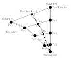
도 2는 본 발명의 일 실시예에 따른 주차 보조 장치 또는 방법에서 차량의 예상 주행 궤적을 산출하는 방법을 설명하기 위한 개념도이다.2 is a conceptual diagram illustrating a method of calculating an expected driving trajectory of a vehicle in a parking assisting apparatus or method according to an embodiment of the present invention.
차량의 예상 주행 궤적은 전방 또는 후방 카메라의 온(On) 시에 차량의 특성을 고려한 최대 조향각(예를 들면, 540°또는 720°)에 따른 주행 궤적(핸들을 최대로 회전시켰을 때의 주행 궤적)과 최소 조향각에 따른 주행 궤적(핸들을 돌리지 않을 때의 직선 주행 궤적)을 기반으로 주행 궤적 내 다수의 좌표를 생성한다.The estimated driving trajectory of the vehicle is a driving trajectory according to the maximum steering angle (for example, 540 ° or 720 °) considering the characteristics of the vehicle when the front or rear camera is on. ) And a plurality of coordinates in the driving trajectory are generated based on the driving trajectory (linear driving trajectory when the steering wheel is not turned) according to the minimum steering angle.
예컨대, 운전자가 최대 조향각과 최소 조향각 사이의 소정의 조향각으로 스티어링 휠을 회전시켰을 때, 도 2와 같이, 소정의 조향각에 따라 'Pn-1', 'Pn-2', 'Pn-3'과 'Pn-4'의 좌표들이 계산될 수 있고, 이 좌표들을 연결한 점선이 예상 주행 궤적이 되는 것이다.For example, when sikyeoteul driver rotates the steering wheel at a predetermined steering angle between a maximum steering angle and a minimum steering angle, as shown in FIG.2, 'P n -1', 'P n -2' according to a predetermined steering angle, 'Pn- The coordinates of3 'and' Pn-4 'can be calculated, and the dotted line connecting these coordinates becomes the expected driving trajectory.
여기서, 송수신부(150)는 조향각 센서(steering angle sensor)가 포함된 조향각 측정 장치로부터 조향각 정보를 직접 수신받도록 구성할 수 있고, 조향각 각도 정보를 수신받을 수 있는 차량에 부속된 대등한 장치 또는 모듈로부터 수신받을 수 있도록 구성할 수도 있다.Here, the transmitter /
이때, 상기 조향각 센서는 주행 중인 차량의 제어에 필요한 스티어링 휠의 조향각을 측정한다.At this time, the steering angle sensor measures the steering angle of the steering wheel required for the control of the driving vehicle.
이후, 본 발명의 일 실시예에 따른 송수신부(150)는 캔 통신에 의해 실시간으로 조향각 정보를 수신받아 제어부로 전달하고, 예상 주행 궤적 생성 및 처리부는 제어부를 통해 전달받은 조향각 정보를 최소 조향각 및 최대 조향각에 대해 비례적으로 좌표를 산출한 후, 각 좌표를 연결하여 차량의 예상 주행 궤적을 생성한다.Then, the
구체적으로 예상 주행 궤적의 X 좌표와 Y 좌표는 각각 하기 관계식에 의하여 정해질 수 있다.(주차 종료 지점이 Pn-4인 경우를 예시함)Specifically, the X coordinate and the Y coordinate of the expected driving trajectory may be determined by the following relations, respectively (exemplifying the casewhere the parking end point is Pn-4 ).
[관계식 1][Relationship 1]
Xn-4= X0-4 -ㅿxXn-4 = X0-4- ㅿ x
[관계식 2][Relation 2]
Yn-4= Y0-4 -ㅿyYn-4 = Y0-4- ㅿ y
이때 X 좌표의 변화량(ㅿx)은 (X0-4 - Xe-4)/(θc/θm)이고, Y 좌표의 변화량(ㅿy)은 (Y0-4 - Ye-4)/(θc/θm)이다(여기서 θm은 최대 조향각이고, θc는 현재 조향각이다).
In this case, the change amount (X) of the X coordinate is (X0-4 -Xe-4 ) / (θc / θm ), and the change amount (Yy) of the Y coordinate is (Y0-4 -Ye-4 ) / (θc / θm ), where θm is the maximum steering angle and θc is the current steering angle.
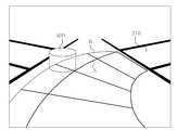
도 3은 본 발명의 일 실시예에 따른 주차 보조 장치 및 방법의 차량의 예상 주행 궤적을 도시한다.3 illustrates an expected driving trajectory of the vehicle of the parking assisting apparatus and method according to an embodiment of the present invention.
점(P)은 차량(310)의 회전 반경의 중심점을 나타낸다. θ1은 점(P)를 중심으로 차량(310)의 앞쪽 좌측바퀴의 각도, θ2는 점(P)를 중심으로 차량(310)의 앞쪽 우측바퀴의 각도를 나타낸다. 차량의 전륜 중 점(P)를 중심으로 큰 원을 형성하는 바퀴를 선택하여, 그 바퀴에 따른 예상 궤적을 도 2와 관련하여 설명한 방법에 따라 계산할 수 있다.Point P represents the center point of the radius of rotation of the
제1 예상 주행 궤적(A)은 차량(310)의 후륜의 주행 궤적을 나타내고, 제2 예상 주행 궤적(B)은 차량(310)의 전륜의 주행 궤적을 나타낸다. 차량(310)의 후륜에 따른 제1 예상 주행 궤적(A)만을 이용하는 경우, 차량의 후방 우측에 있는 장애물과의 충돌을 예상하기 어렵다. 이런 경우, 운전자들은 차량을 천천히 주행하도록 하여 실제로 차량이 장애물에 충돌하는지 여부를 차량 내의 전방 또는 후방 디스플레이부 뿐만 아니라 사이드미러를 통해 직접 육안으로 확인할 수 있다.The first expected travel trajectory A represents the travel trajectory of the rear wheel of the
이에, 본 발명의 일 실시예에 따른 주차 보조 장치 및 방법은 차량(310)의 전륜에 따른 제2 예상 주행 궤적(B)을 추가로 제공하여, 운전자가 장애물과의 충돌가능성을 차량 내의 디스플레이부를 통해 미리 인지할 수 있도록 하고 더 나아가서는 장애물과의 충돌을 예방할 수 있도록 한다.Accordingly, the parking assisting apparatus and method according to an exemplary embodiment of the present invention further provide a second expected driving trajectory B along the front wheel of the
도 3에 도시되는 것처럼, 본 발명의 일 실시예에 따른 주차 보조 장치 및 방법은 제1 예상 주행 궤적(A) 및 제2 예상 주행 궤적(B)을 함께 디스플레이하여 운전자에게 제공할 수 있다.As illustrated in FIG. 3, the parking assisting apparatus and method according to an exemplary embodiment may display the first expected driving trajectory A and the second expected driving trajectory B together to provide the driver.
따라서, 본 발명의 일 실시예에 따른 주차 보조 장치 및 방법은 전륜 및 후륜 모두에 따른 예상 주행 궤적을 제공함으로써, 실제 주행 궤적과의 오차를 줄일 수 있고 이를 통해 장애물과의 충돌을 회피할 수 있다.
Therefore, the parking assisting apparatus and method according to an embodiment of the present invention can provide an expected driving trajectory along both the front wheel and the rear wheel, thereby reducing an error with the actual driving trajectory and avoiding collision with an obstacle. .
도 4는 종래 기술에 따른 주차 보조 장치 및 방법의 디스플레이 장면을 도시한다. 주차목표영역(410)에 도달하기 위해 운전자가 스티어링 휠을 조종하면, 차량의 제1 예상 주행 궤적(A)이 디스플레이부에 표시될 수 있다.4 shows a display scene of a parking assist device and method according to the prior art. When the driver controls the steering wheel to reach the
도 4에서 도시되는 것처럼, 차량(미도시)의 후륜의 예상 주행 궤적(A)만을 표시한 경우에는 장애물(400)과의 충돌 여부를 운전자가 이 디스플레이 장면을 통해 쉽게 판단할 수 없다.
As shown in FIG. 4, when only the expected driving trajectory A of the rear wheel of the vehicle (not shown) is displayed, the driver may not easily determine whether or not the vehicle collides with the
도 5는 본 발명의 일 실시예에 따른 주차 보조 장치 및 방법의 디스플레이 장면을 도시한다. 주차목표영역(510)에 도달하기 위해 운전자가 스티어링 휠을 조종하면, 차량의 제1 예상 주행 궤적(A)이 디스플레이부에 표시될 수 있다. 또한, 차량의 제2 예상 주행 궤적(B)이 동시에 디스플레이부에 표시될 수 있다.5 shows a display scene of the parking assisting apparatus and method according to an embodiment of the present invention. When the driver controls the steering wheel to reach the
제2 예상 주행 궤적(B)은 차량의 전륜의 예상 주행 궤적을 계산하여 나타낸 것으로, 이 경우 차량의 후방에 있는 장애물(500)과의 충돌 가능성을 운전자가 인지할 수 있도록 한다.The second predicted driving trajectory B calculates and displays an expected driving trajectory of the front wheel of the vehicle, and in this case, the driver may recognize a possibility of collision with the
도 5에서 도시되는 것처럼, 제1 예상 주행 궤적(A) 및 제2 예상 주행 궤적(B)을 함께 표시한 경우에는 장애물(500)과의 충돌 여부를 운전자가 이 디스플레이 장면을 통해 쉽게 판단할 수 있다.As shown in FIG. 5, when the first expected driving trajectory A and the second expected driving trajectory B are displayed together, the driver can easily determine whether or not the collision with the
추가적으로, 제1 또는 제2 예상 주행 궤적 상에 감지된 장애물이 존재하는 경우, 제1 또는 제2 예상 주행 궤적을 다른 색으로 표시하거나 깜박이게 하는 등 시각적인 수단을 이용하여 운전자에게 알릴 수 있다. 또한, 이러한 경우에 경고 문구 등을 함께 출력하여 운전자의 주의를 끌 수 있다.
In addition, when a detected obstacle exists on the first or second expected driving trajectory, the driver may be notified by using visual means such as displaying or blinking the first or second expected driving trajectory in a different color. In addition, in such a case, a warning phrase or the like may be output together to draw attention of the driver.
도 6은 본 발명의 일 실시예에 따른 주차 보조 방법의 순서도를 도시한다.6 is a flowchart illustrating a parking assisting method according to an embodiment of the present invention.
본 발명의 일 실시예에 따른 주차 보조를 위한 방법은 상기 차량의 전방 또는 후방 영상을 획득하는 단계(S610); 상기 차량의 조향각 정보에 따라 상기 차량의 예상 주행 궤적을 생성하는 단계(S620); 상기 차량의 예상 주행 궤적을 상기 차량의 전방 또는 후방 영상에 오버레이하는 단계(S630); 및 상기 오버레이된 상기 차량의 전방 또는 후방 영상 및 상기 차량의 예상 주행 궤적을 함께 디스플레이하는 단계(S640)를 포함할 수 있다.According to one or more exemplary embodiments, a method for assisting parking includes obtaining a front or rear image of the vehicle (S610); Generating an expected driving trajectory of the vehicle according to the steering angle information of the vehicle (S620); Overlaying an expected driving trajectory of the vehicle on a front or rear image of the vehicle (S630); And displaying the front or rear image of the overlaid vehicle and the expected driving trajectory of the vehicle together (S640).
상기 차량의 예상 주행 궤적은 상기 차량의 후륜에 따른 제1 예상 주행 궤적과 상기 차량의 전륜에 따른 제2 예상 주행 궤적을 포함할 수 있다.The predicted driving trajectory of the vehicle may include a first predicted driving trajectory along the rear wheel of the vehicle and a second predicted driving trajectory along the front wheel of the vehicle.
단계(S610)는 차량에 장착된 카메라 또는 카메라 모듈을 통해 상기 차량의 전방 또는 후방의 영상을 촬영하는 단계로서, 구체적으로는 이미지 센서가 상기 차량의 전방 또는 후방의 영상을 획득할 수 있다.In operation S610, an image of the front or the rear of the vehicle is photographed by a camera or a camera module mounted on the vehicle. Specifically, the image sensor may acquire an image of the front or the rear of the vehicle.
단계(S620)는 차량의 조향각 센서로부터 조향각 정보를 제공받아 이를 이용하여 상기 차량의 예상 주행 궤적을 생성할 수 있다. 단계(S620)는 상기 차량의 전륜에 따른 제1 예상 주행 궤적과 상기 차량의 후륜에 따른 제2 예상 주행 궤적을 생성할 수 있다. 이렇게 생성된 제1 및 제2 예상 주행 궤적을 단계(S610)에서 획득한 차량의 전방 또는 후방의 영상에 오버레이할 수 있다(S630).In operation S620, the steering angle information may be received from the steering angle sensor of the vehicle to generate an expected driving trajectory of the vehicle. In operation S620, a first expected driving trajectory along the front wheel of the vehicle and a second expected driving trajectory along the rear wheel of the vehicle may be generated. The first and second anticipated driving trajectories generated as described above may be overlaid on the image of the front or the rear of the vehicle obtained in step S610 (S630).
또한, 단계(S640)는 예상 주행 궤적과 차량의 전방 또는 후방 영상이 오버레이된 장면을 디스플레이부에 표시할 수 있다.In operation S640, a scene in which the predicted driving trajectory and the front or rear image of the vehicle are overlaid may be displayed on the display unit.
종래에 사용된 차량의 예상 주행 궤적은 차량의 후륜의 예상 주행 궤적만을 제공했거나, 또는 하나의 예상 주행 궤적만을 제공하여, 주차시의 장애물 등과의 충돌에 대한 예방 효과가 미미했고 차량의 실제 주행 궤적과의 오차가 존재하여 주차 보조 기능의 신뢰도가 낮았다.The anticipated driving trajectory of the vehicle used in the related art provided only the anticipated driving trajectory of the rear wheel of the vehicle, or provided only one anticipated driving trajectory, so that the effect of preventing the collision with an obstacle when parking was insignificant and the actual driving trajectory of the vehicle was insignificant. There was an error of, and the reliability of the parking assistance function was low.
그러나, 본 발명의 일 실시예에 따른 주차 보조 장치 및 방법에 의하면, 차량의 전륜 및 후륜 각각에 따른 예상 주행 궤적을 디스플레이부를 통해 제공하여 차량의 실제 주행 궤적과의 오차를 줄여 주차 보조 기능의 신뢰도를 향상시켰으며, 이를 통해 주차시의 장애물 등과의 충돌을 방지할 수 있다.
However, according to the parking assisting apparatus and method according to an embodiment of the present invention, by providing the expected driving trajectories for each of the front and rear wheels of the vehicle through the display unit to reduce the error with the actual driving trajectory of the vehicle reliability of the parking assistance function It has been improved, through which it is possible to prevent collisions with obstacles when parking.
위에서 본 발명의 실시예들이 설명되었으며, 당해 기술 분야에 속한 통상의 지식을 가진 자는 이러한 실시예들은 발명을 한정하기 위한 것이 아니라 단지 예시적인 것임을 인식할 수 있고, 본 발명의 범위 또는 사상을 벗어나지 않고 변형, 수정 등이 가능함을 인식할 것이다.
Having described the embodiments of the present invention above, those of ordinary skill in the art will recognize that these embodiments are illustrative rather than limiting, and that various changes and modifications may be made without departing from the scope or spirit of the invention Variations, and modifications may be made without departing from the scope of the present invention.
110: 이미지센서120: 메모리
130: 제어부140: 예상 주행 궤적 생성 및 처리부
150: 송수신부160: 디스플레이부110: image sensor 120: memory
130: control unit 140: predicted driving trajectory generation and processing unit
150: transceiver 160: display
Claims (15)
Translated fromKorean상기 차량의 조향각 정보를 이용하여 주차목표영역까지의 예상 주행 궤적을 생성하고, 상기 촬영된 차량의 전방 또는 후방의 영상에 상기 예상 주행 궤적을 오버레이(overlay)하는 예상 주행 궤적 생성 및 처리부;및
상기 오버레이된 상기 차량의 전방 또는 후방의 영상 및 상기 예상 주행 궤적을 함께 표시하는 디스플레이부를 포함하고,
상기 예상 주행 궤적은 상기 차량의 후륜에 따른 제1 예상 주행 궤적과 상기 차량의 전륜에 따른 제2 예상 주행 궤적을 포함하고,
상기 제1 예상 주행 궤적 및 상기 제2 예상 주행 궤적은 상기 차량의 최대 조향각 주행 궤적과 최소 조향각의 주행 궤적을 기반으로 주행궤적 내 다수의 좌표를 생성하여, 실시간으로 차량의 조향각 정보를 받아 최소 조향각 및 최대 조향각과 비례적으로 예상 좌표를 산출하여 생성되고,
상기 차량의 스티어링 휠의 조향각에 따라 실시간으로 업데이트되는, 주차 보조 장치.
An image sensor for capturing an image of the front or rear of the vehicle;
An expected driving trajectory generation and processing unit generating an expected driving trajectory to the parking target area by using the steering angle information of the vehicle and overlaying the expected driving trajectory on an image of the front or rear of the photographed vehicle; and
And a display unit which displays the image of the front or rear side of the overlaid vehicle and the expected driving trajectory together.
The expected driving trajectory includes a first expected driving trajectory along the rear wheel of the vehicle and a second expected driving trajectory along the front wheel of the vehicle,
The first predicted driving trajectory and the second predicted driving trajectory generate a plurality of coordinates in the driving trajectory based on the driving trajectory of the maximum steering angle driving trajectory and the minimum steering angle of the vehicle, and receive the steering angle information of the vehicle in real time to obtain the minimum steering angle. And calculating the expected coordinates in proportion to the maximum steering angle,
Parking assistance apparatus is updated in real time according to the steering angle of the steering wheel of the vehicle.
상기 차량의 조향각 정보에 따라 상기 차량의 예상 주행 궤적을 생성하는 단계;
상기 차량의 예상 주행 궤적을 상기 차량의 전방 또는 후방 영상에 오버레이하는 단계; 및
상기 오버레이된 상기 차량의 전방 또는 후방 영상 및 상기 차량의 예상 주행 궤적을 함께 디스플레이하는 단계를 포함하고,
상기 차량의 예상 주행 궤적은 상기 차량의 후륜에 따른 제1 예상 주행 궤적과 상기 차량의 전륜에 따른 제2 예상 주행 궤적을 포함하고, 상기 제1 예상 주행 궤적 및 상기 제2 예상 주행 궤적은 상기 차량의 스티어링 휠의 조향각에 따라 실시간으로 업데이트되며,
상기 제1 예상 주행 궤적 또는 제2 예상 주행 궤적 상에 감지된 장애물이 존재하는 경우, 상기 제1 예상 주행 궤적 또는 제2 예상 주행 궤적을 다른 색으로 표시하거나 깜박이게 하는 주차 보조 방법.
Obtaining a front or rear image of the vehicle;
Generating an expected driving trajectory of the vehicle according to the steering angle information of the vehicle;
Overlaying an expected driving trajectory of the vehicle on a front or rear image of the vehicle; And
Displaying the front or rear image of the overlaid vehicle and the predicted driving trajectory of the vehicle together;
The predicted driving trajectory of the vehicle includes a first predicted driving trajectory along the rear wheel of the vehicle and a second predicted driving trajectory along the front wheel of the vehicle, and the first predicted driving trajectory and the second predicted driving trajectory are the vehicle. It is updated in real time according to the steering angle of the steering wheel,
And when the detected obstacle exists on the first expected driving trajectory or the second expected driving trajectory, the first predicted driving trajectory or the second predicted driving trajectory is displayed in a different color or blinks.
상기 차량의 조향각 정보를 이용하여 주차목표영역까지의 예상 주행 궤적을 생성하고, 상기 촬영된 차량의 전방 또는 후방의 영상에 상기 예상 주행 궤적을 오버레이(overlay)하는 예상 주행 궤적 생성 및 처리부;
상기 오버레이된 상기 차량의 전방 또는 후방의 영상 및 상기 예상 주행 궤적을 함께 표시하는 디스플레이부; 및
상기 이미지 센서 및 상기 예상 주행 궤적 생성 및 처리부의 동작을 제어하고, 조향각 센서를 포함하는 외부의 모듈 또는 유닛으로부터 데이터를 수신하여 처리하기 위한 제어부를 포함하고,
상기 예상 주행 궤적은 상기 차량의 후륜의 예상 주행 궤적을 나타내는 제1 예상 주행 궤적과 상기 차량의 전륜의 예상 주행 궤적을 나타내는 제2 예상 주행 궤적을 포함하고,
상기 제어부는 주차시 상기 차량의 스티어링 휠의 조향각에 따라 송수신부를 통해 실시간으로 차량의 조향각 정보 또는 속도 정보를 수신하고, 상기 송수신부를 통해 수신한 조향각 정보를 상기 예상 주행 궤적 생성부 및 처리부로 전달하며,
상기 예상 주행 궤적 생성 및 처리부는 전방 또는 후방 카메라의 온(ON)시, 상기 차량의 스티어링 휠의 조향각을 실시간으로 업데이트하여 상기 제1 예상 주행 궤적 및 상기 제2 예상 주행 궤적을 생성하고,
상기 제1 예상 주행 궤적과 제2 예상 주행 궤적을 상기 차량의 전방 또는 후방의 영상에 함께 오버레이하여 상기 디스플레이부에 동시에 표시하고 주차시 상기 차량과 장애물과의 충돌 가능성을 알려주는 주차 보조 장치.
An image sensor for capturing an image of the front or rear of the vehicle;
An expected driving trajectory generation and processing unit for generating an expected driving trajectory to the parking target area by using the steering angle information of the vehicle and overlaying the expected driving trajectory on an image of the front or rear of the photographed vehicle;
A display unit for displaying the image of the front or rear of the overlaid vehicle and the expected driving trajectory together; And
A control unit for controlling operations of the image sensor and the expected driving trajectory generation and processing unit, and receiving and processing data from an external module or unit including a steering angle sensor,
The anticipated driving trajectory includes a first anticipated driving trajectory indicating a predicted driving trajectory of the rear wheel of the vehicle and a second predicted driving trajectory indicating an expected driving trajectory of the front wheel of the vehicle,
The controller receives steering angle information or speed information of the vehicle in real time according to the steering angle of the steering wheel of the vehicle and transmits the steering angle information received through the transceiver to the expected driving trajectory generation unit and the processing unit. ,
The predicted driving trajectory generation and processing unit generates the first expected driving trajectory and the second expected driving trajectory by updating the steering angle of the steering wheel of the vehicle in real time when the front or rear camera is turned on.
And overlaying the first and second expected driving trajectories on an image of the front or the rear of the vehicle simultaneously and displaying them on the display unit, and notifying the possibility of collision between the vehicle and an obstacle when parking.
상기 차량의 전방 또는 후방의 영상과, 주차 영역 표시선, 주차목표영역, 경고 문구 이미지 중 적어도 어느 하나를 합성하는 주차 보조 장치.
The method of claim 6, wherein the image sensor,
Parking assistance device for synthesizing at least one of the image of the front or rear of the vehicle, the parking area display line, the parking target area, the warning text image.
주차모드 또는 주차방향에 따라 가변되는 주차 보조 장치.
The method of claim 7, wherein the parking area display line,
Parking assistance device that varies depending on the parking mode or direction of parking.
평행주차 또는 직각주차인 주차 보조 장치.
The method of claim 8, wherein the parking mode,
Parking aids for parallel or square parking.
좌측방향 또는 우측방향인 주차 보조 장치.
The method of claim 8, wherein the parking direction,
Parking assist device left or right.
Priority Applications (3)
| Application Number | Priority Date | Filing Date | Title |
|---|---|---|---|
| KR1020110102559AKR101329510B1 (en) | 2011-10-07 | 2011-10-07 | An apparatus and method for assisting parking |
| US14/350,245US9959769B2 (en) | 2011-10-07 | 2011-11-21 | Apparatus and method for assisting parking |
| PCT/KR2011/008860WO2013051753A1 (en) | 2011-10-07 | 2011-11-21 | An apparatus and method for assisting parking |
Applications Claiming Priority (1)
| Application Number | Priority Date | Filing Date | Title |
|---|---|---|---|
| KR1020110102559AKR101329510B1 (en) | 2011-10-07 | 2011-10-07 | An apparatus and method for assisting parking |
Publications (2)
| Publication Number | Publication Date |
|---|---|
| KR20130037968A KR20130037968A (en) | 2013-04-17 |
| KR101329510B1true KR101329510B1 (en) | 2013-11-13 |
Family
ID=48043904
Family Applications (1)
| Application Number | Title | Priority Date | Filing Date |
|---|---|---|---|
| KR1020110102559AActiveKR101329510B1 (en) | 2011-10-07 | 2011-10-07 | An apparatus and method for assisting parking |
Country Status (3)
| Country | Link |
|---|---|
| US (1) | US9959769B2 (en) |
| KR (1) | KR101329510B1 (en) |
| WO (1) | WO2013051753A1 (en) |
Families Citing this family (10)
| Publication number | Priority date | Publication date | Assignee | Title |
|---|---|---|---|---|
| KR101803973B1 (en)* | 2011-05-09 | 2017-12-01 | 엘지이노텍 주식회사 | Parking camera system and method of driving the same |
| JP5888087B2 (en) | 2012-04-25 | 2016-03-16 | ソニー株式会社 | Driving support image generation device, driving support image generation method, in-vehicle camera, and device operation support image generation device |
| US10683035B2 (en)* | 2015-12-08 | 2020-06-16 | Panasonic Intellectual Property Management Co., Ltd. | Parking assistance device, parking assistance method, and non-transitory computer readable medium |
| DE102016210632A1 (en)* | 2016-06-15 | 2017-12-21 | Bayerische Motoren Werke Aktiengesellschaft | Method for checking a media loss of a motor vehicle and motor vehicle and system for carrying out such a method |
| US9915948B2 (en)* | 2016-07-14 | 2018-03-13 | Mitsubishi Electric Research Laboratories, Inc. | System and method for controlling motion of vehicle |
| JP2018144567A (en)* | 2017-03-02 | 2018-09-20 | アイシン精機株式会社 | Driving support device |
| CN110530390A (en)* | 2019-09-16 | 2019-12-03 | 哈尔滨工程大学 | A kind of non-particle vehicle path planning method under narrow environment |
| US11772555B2 (en)* | 2019-10-07 | 2023-10-03 | Hyundai Motor Company | Vehicle and method of providing surrounding information thereof |
| JP7559535B2 (en)* | 2020-12-14 | 2024-10-02 | 株式会社デンソー | Vehicle display control device and vehicle display control method |
| KR102682768B1 (en)* | 2022-11-24 | 2024-07-12 | 에이치디현대건설기계 주식회사 | Rear Safety System of Construction Equipment |
Citations (2)
| Publication number | Priority date | Publication date | Assignee | Title |
|---|---|---|---|---|
| JP2005306335A (en) | 2004-04-26 | 2005-11-04 | Toyota Industries Corp | Turning radius calculating method, steering support device and parking support device using turning radius calculating method, turning radius calculating program, and recording medium |
| KR20080096905A (en)* | 2007-04-30 | 2008-11-04 | 현대자동차주식회사 | How to park your car |
Family Cites Families (5)
| Publication number | Priority date | Publication date | Assignee | Title |
|---|---|---|---|---|
| AU2001243285A1 (en)* | 2000-03-02 | 2001-09-12 | Donnelly Corporation | Video mirror systems incorporating an accessory module |
| US6825779B2 (en)* | 2000-06-30 | 2004-11-30 | Matsushita Electric Industrial Co., Ltd. | Rendering device |
| JP2004123057A (en)* | 2002-10-07 | 2004-04-22 | Yazaki Corp | Parking assistance device |
| JP2010076675A (en)* | 2008-09-26 | 2010-04-08 | Toyota Motor Corp | Vehicular parking assisting device and parking assisting method for vehicle |
| JP5035321B2 (en)* | 2009-11-02 | 2012-09-26 | 株式会社デンソー | Vehicle periphery display control device and program for vehicle periphery display control device |
- 2011
- 2011-10-07KRKR1020110102559Apatent/KR101329510B1/enactiveActive
- 2011-11-21USUS14/350,245patent/US9959769B2/enactiveActive
- 2011-11-21WOPCT/KR2011/008860patent/WO2013051753A1/enactiveApplication Filing
Patent Citations (3)
| Publication number | Priority date | Publication date | Assignee | Title |
|---|---|---|---|---|
| JP2005306335A (en) | 2004-04-26 | 2005-11-04 | Toyota Industries Corp | Turning radius calculating method, steering support device and parking support device using turning radius calculating method, turning radius calculating program, and recording medium |
| KR20060036929A (en)* | 2004-04-26 | 2006-05-02 | 가부시키가이샤 도요다 지도숏키 | Rotation radius calculation method, steering assist device and parking assist device using the rotation radius calculation method, rotation radius calculation program and recording medium |
| KR20080096905A (en)* | 2007-04-30 | 2008-11-04 | 현대자동차주식회사 | How to park your car |
Also Published As
| Publication number | Publication date |
|---|---|
| US20140285665A1 (en) | 2014-09-25 |
| US9959769B2 (en) | 2018-05-01 |
| KR20130037968A (en) | 2013-04-17 |
| WO2013051753A1 (en) | 2013-04-11 |
Similar Documents
| Publication | Publication Date | Title |
|---|---|---|
| KR101329510B1 (en) | An apparatus and method for assisting parking | |
| US10369989B2 (en) | Parking assistance system and method for controlling the same | |
| US9852346B2 (en) | Trailer track estimation system and method by image recognition | |
| US9731764B2 (en) | Automatic parking controlling apparatus and method of vehicle | |
| EP2981077B1 (en) | Periphery monitoring device and program | |
| KR20130037274A (en) | An apparatus and method for assisting parking using the multi-view cameras | |
| CN102458964B (en) | Camera systems for parking vehicles | |
| CN103991448B (en) | Dynamic lane line detection system and method | |
| KR101803973B1 (en) | Parking camera system and method of driving the same | |
| EP2786917A2 (en) | Birds-eye view parking assist system and method | |
| CN107615757B (en) | Information presentation system | |
| US11097733B2 (en) | Apparatus and method for controlling reverse driving | |
| CN108216033B (en) | Vehicle Peripheral Monitoring Device | |
| JP2014532324A (en) | Driving assistance system to assist drivers in situations related to collisions | |
| US10872249B2 (en) | Display control device, display control system, display control method, and non-transitory storage medium | |
| JP5182137B2 (en) | Vehicle periphery display device | |
| JP2011175508A (en) | Parking support system | |
| KR20120094397A (en) | Automobile camera module and method of guiding parking | |
| WO2010134240A1 (en) | Parking assistance device, parking assistance method, and parking assistance program | |
| KR20130052855A (en) | Parking guide system using image and parking guide method | |
| JP5445218B2 (en) | Parking assistance system | |
| JP5504968B2 (en) | Parking assistance system | |
| US20120086798A1 (en) | System and method for automatic dynamic guidelines | |
| KR101798054B1 (en) | System and Method for Laser Guide | |
| CN111942387A (en) | Driving assistance method, device and system for vehicle and vehicle |
Legal Events
| Date | Code | Title | Description |
|---|---|---|---|
| A201 | Request for examination | ||
| PA0109 | Patent application | Patent event code:PA01091R01D Comment text:Patent Application Patent event date:20111007 | |
| PA0201 | Request for examination | ||
| E902 | Notification of reason for refusal | ||
| PE0902 | Notice of grounds for rejection | Comment text:Notification of reason for refusal Patent event date:20130117 Patent event code:PE09021S01D | |
| AMND | Amendment | ||
| PG1501 | Laying open of application | ||
| E601 | Decision to refuse application | ||
| PE0601 | Decision on rejection of patent | Patent event date:20130626 Comment text:Decision to Refuse Application Patent event code:PE06012S01D Patent event date:20130117 Comment text:Notification of reason for refusal Patent event code:PE06011S01I | |
| AMND | Amendment | ||
| PX0901 | Re-examination | Patent event code:PX09011S01I Patent event date:20130626 Comment text:Decision to Refuse Application Patent event code:PX09012R01I Patent event date:20130312 Comment text:Amendment to Specification, etc. | |
| PX0701 | Decision of registration after re-examination | Patent event date:20130813 Comment text:Decision to Grant Registration Patent event code:PX07013S01D Patent event date:20130726 Comment text:Amendment to Specification, etc. Patent event code:PX07012R01I Patent event date:20130626 Comment text:Decision to Refuse Application Patent event code:PX07011S01I Patent event date:20130312 Comment text:Amendment to Specification, etc. Patent event code:PX07012R01I | |
| X701 | Decision to grant (after re-examination) | ||
| GRNT | Written decision to grant | ||
| PR0701 | Registration of establishment | Comment text:Registration of Establishment Patent event date:20131107 Patent event code:PR07011E01D | |
| PR1002 | Payment of registration fee | Payment date:20131107 End annual number:3 Start annual number:1 | |
| PG1601 | Publication of registration | ||
| FPAY | Annual fee payment | Payment date:20161006 Year of fee payment:4 | |
| PR1001 | Payment of annual fee | Payment date:20161006 Start annual number:4 End annual number:4 | |
| FPAY | Annual fee payment | Payment date:20181010 Year of fee payment:6 | |
| PR1001 | Payment of annual fee | Payment date:20181010 Start annual number:6 End annual number:6 | |
| FPAY | Annual fee payment | Payment date:20191010 Year of fee payment:7 | |
| PR1001 | Payment of annual fee | Payment date:20191010 Start annual number:7 End annual number:7 | |
| PR1001 | Payment of annual fee | Payment date:20201013 Start annual number:8 End annual number:8 | |
| PR1001 | Payment of annual fee | Payment date:20211013 Start annual number:9 End annual number:9 | |
| PR1001 | Payment of annual fee | Payment date:20221011 Start annual number:10 End annual number:10 | |
| PR1001 | Payment of annual fee | Payment date:20231012 Start annual number:11 End annual number:11 | |
| PR1001 | Payment of annual fee | Payment date:20241015 Start annual number:12 End annual number:12 |