KR101328574B1 - Apparatus for transferring substrate - Google Patents
Apparatus for transferring substrateDownload PDFInfo
- Publication number
- KR101328574B1 KR101328574B1KR1020120106111AKR20120106111AKR101328574B1KR 101328574 B1KR101328574 B1KR 101328574B1KR 1020120106111 AKR1020120106111 AKR 1020120106111AKR 20120106111 AKR20120106111 AKR 20120106111AKR 101328574 B1KR101328574 B1KR 101328574B1
- Authority
- KR
- South Korea
- Prior art keywords
- magnet
- tray
- substrate
- shaft
- coupled
- Prior art date
- Legal status (The legal status is an assumption and is not a legal conclusion. Google has not performed a legal analysis and makes no representation as to the accuracy of the status listed.)
- Expired - Fee Related
Links
Images


Classifications
- B—PERFORMING OPERATIONS; TRANSPORTING
- B65—CONVEYING; PACKING; STORING; HANDLING THIN OR FILAMENTARY MATERIAL
- B65G—TRANSPORT OR STORAGE DEVICES, e.g. CONVEYORS FOR LOADING OR TIPPING, SHOP CONVEYOR SYSTEMS OR PNEUMATIC TUBE CONVEYORS
- B65G49/00—Conveying systems characterised by their application for specified purposes not otherwise provided for
- B65G49/05—Conveying systems characterised by their application for specified purposes not otherwise provided for for fragile or damageable materials or articles
- B65G49/06—Conveying systems characterised by their application for specified purposes not otherwise provided for for fragile or damageable materials or articles for fragile sheets, e.g. glass
- B65G49/061—Lifting, gripping, or carrying means, for one or more sheets forming independent means of transport, e.g. suction cups, transport frames
- B—PERFORMING OPERATIONS; TRANSPORTING
- B65—CONVEYING; PACKING; STORING; HANDLING THIN OR FILAMENTARY MATERIAL
- B65G—TRANSPORT OR STORAGE DEVICES, e.g. CONVEYORS FOR LOADING OR TIPPING, SHOP CONVEYOR SYSTEMS OR PNEUMATIC TUBE CONVEYORS
- B65G54/00—Non-mechanical conveyors not otherwise provided for
- B65G54/02—Non-mechanical conveyors not otherwise provided for electrostatic, electric, or magnetic
- F—MECHANICAL ENGINEERING; LIGHTING; HEATING; WEAPONS; BLASTING
- F16—ENGINEERING ELEMENTS AND UNITS; GENERAL MEASURES FOR PRODUCING AND MAINTAINING EFFECTIVE FUNCTIONING OF MACHINES OR INSTALLATIONS; THERMAL INSULATION IN GENERAL
- F16H—GEARING
- F16H49/00—Other gearings
- F16H49/005—Magnetic gearings with physical contact between gears
- G—PHYSICS
- G02—OPTICS
- G02F—OPTICAL DEVICES OR ARRANGEMENTS FOR THE CONTROL OF LIGHT BY MODIFICATION OF THE OPTICAL PROPERTIES OF THE MEDIA OF THE ELEMENTS INVOLVED THEREIN; NON-LINEAR OPTICS; FREQUENCY-CHANGING OF LIGHT; OPTICAL LOGIC ELEMENTS; OPTICAL ANALOGUE/DIGITAL CONVERTERS
- G02F1/00—Devices or arrangements for the control of the intensity, colour, phase, polarisation or direction of light arriving from an independent light source, e.g. switching, gating or modulating; Non-linear optics
- G02F1/01—Devices or arrangements for the control of the intensity, colour, phase, polarisation or direction of light arriving from an independent light source, e.g. switching, gating or modulating; Non-linear optics for the control of the intensity, phase, polarisation or colour
- G02F1/13—Devices or arrangements for the control of the intensity, colour, phase, polarisation or direction of light arriving from an independent light source, e.g. switching, gating or modulating; Non-linear optics for the control of the intensity, phase, polarisation or colour based on liquid crystals, e.g. single liquid crystal display cells
- G02F1/1303—Apparatus specially adapted to the manufacture of LCDs
- H—ELECTRICITY
- H01—ELECTRIC ELEMENTS
- H01L—SEMICONDUCTOR DEVICES NOT COVERED BY CLASS H10
- H01L21/00—Processes or apparatus adapted for the manufacture or treatment of semiconductor or solid state devices or of parts thereof
- H01L21/67—Apparatus specially adapted for handling semiconductor or electric solid state devices during manufacture or treatment thereof; Apparatus specially adapted for handling wafers during manufacture or treatment of semiconductor or electric solid state devices or components ; Apparatus not specifically provided for elsewhere
- H01L21/677—Apparatus specially adapted for handling semiconductor or electric solid state devices during manufacture or treatment thereof; Apparatus specially adapted for handling wafers during manufacture or treatment of semiconductor or electric solid state devices or components ; Apparatus not specifically provided for elsewhere for conveying, e.g. between different workstations
- H01L21/67703—Apparatus specially adapted for handling semiconductor or electric solid state devices during manufacture or treatment thereof; Apparatus specially adapted for handling wafers during manufacture or treatment of semiconductor or electric solid state devices or components ; Apparatus not specifically provided for elsewhere for conveying, e.g. between different workstations between different workstations
- H01L21/67709—Apparatus specially adapted for handling semiconductor or electric solid state devices during manufacture or treatment thereof; Apparatus specially adapted for handling wafers during manufacture or treatment of semiconductor or electric solid state devices or components ; Apparatus not specifically provided for elsewhere for conveying, e.g. between different workstations between different workstations using magnetic elements
- H—ELECTRICITY
- H01—ELECTRIC ELEMENTS
- H01L—SEMICONDUCTOR DEVICES NOT COVERED BY CLASS H10
- H01L21/00—Processes or apparatus adapted for the manufacture or treatment of semiconductor or solid state devices or of parts thereof
- H01L21/67—Apparatus specially adapted for handling semiconductor or electric solid state devices during manufacture or treatment thereof; Apparatus specially adapted for handling wafers during manufacture or treatment of semiconductor or electric solid state devices or components ; Apparatus not specifically provided for elsewhere
- H01L21/677—Apparatus specially adapted for handling semiconductor or electric solid state devices during manufacture or treatment thereof; Apparatus specially adapted for handling wafers during manufacture or treatment of semiconductor or electric solid state devices or components ; Apparatus not specifically provided for elsewhere for conveying, e.g. between different workstations
- H01L21/67703—Apparatus specially adapted for handling semiconductor or electric solid state devices during manufacture or treatment thereof; Apparatus specially adapted for handling wafers during manufacture or treatment of semiconductor or electric solid state devices or components ; Apparatus not specifically provided for elsewhere for conveying, e.g. between different workstations between different workstations
- H01L21/6773—Conveying cassettes, containers or carriers
Landscapes
- Engineering & Computer Science (AREA)
- Physics & Mathematics (AREA)
- Manufacturing & Machinery (AREA)
- General Physics & Mathematics (AREA)
- Microelectronics & Electronic Packaging (AREA)
- Computer Hardware Design (AREA)
- Condensed Matter Physics & Semiconductors (AREA)
- Power Engineering (AREA)
- Nonlinear Science (AREA)
- General Engineering & Computer Science (AREA)
- Chemical & Material Sciences (AREA)
- Crystallography & Structural Chemistry (AREA)
- Optics & Photonics (AREA)
- Mechanical Engineering (AREA)
- Container, Conveyance, Adherence, Positioning, Of Wafer (AREA)
Abstract
Translated fromKoreanDescription
Translated fromKorean본 발명은 기판이송장치에 관한 것이다. 보다 상세하게는, 기판이 안착되는 트레이를 지지하면서 이송시키기 위한 기판이송장치에 관한 것이다.
The present invention relates to a substrate transfer apparatus. More particularly, the present invention relates to a substrate transfer apparatus for transferring a tray on which a substrate is placed while supporting the same.
최근, 정보기기에 대한 수요증가에 의하여, 정보기기에 정보를 표시할 수 있는 LCD(Liquid Crystal Display), OLED(Organic Light Emitting Diodes) 디스플레이와 같은 영상표시장치의 수요가 증가하고 있다. 위와 같은 평면패널 디스플레이는 더 많은 정보를 쾌적하게 표시하고자 대형화 되고 있으며, 디스플레이 제조공정의 효율화를 위하여 디스플레이 패널의 대면적화가 진행되고 있다. 최근에는 한 변의 길이가 2미터 이상에 이르는 8세대 기판의 생산이 시도 되고 있다.2. Description of the Related Art In recent years, there has been an increasing demand for image display devices such as an LCD (Liquid Crystal Display) and OLED (Organic Light Emitting Diodes) display capable of displaying information on information devices due to an increase in demand for information devices. The above-mentioned flat panel display has been enlarged to display more information comfortably, and the display panel has been made larger in order to make the display manufacturing process more efficient. In recent years, production of an 8th generation substrate having a length of at least 2 meters on one side has been attempted.
이러한 평면패널 디스플레이의 제조공정은 기판에 대한 소성 등을 수행하는 전처리과정, 처리된 기판에 전극을 형성하는 전극형성과정, 형성된 전극 위에 색상 발현층을 형성하는 색상 발현층 형성과정 및 처리된 기판을 디스플레이 패널로 가공하는 후처리과정 등 네 단계로 나눌 수 있다.The fabrication process of the flat panel display includes a preprocessing process for performing firing and the like on the substrate, an electrode formation process for forming an electrode on the processed substrate, a color development layer formation process for forming a color development layer on the formed electrode, And a post-processing process for processing the display panel.
그러나, 기판이 대면적화 될수록 기판의 무게가 증가하게 되며, 기판을 이송하는데 사용되는 트레이의 무게 또한 증가하게 된다. 기판과 트레이의 무게가 증가됨에 따라 트레이를 이송하는 이송장치와 마찰이 증가하게 되며, 마찰로 인하여 트레이 및 기판이송장치에서 파티클이 발생하는 문제가 있다. 이송과정 중에 발생하는 파티클 중 일부는 기판에 부착될 수 있으며, 기판의 불량률을 높이는 원인이 된다. 또한, 트레이의 하중에 의한 기판이송장치의 손상발생 등의 문제가 있다.
However, as the substrate becomes larger, the weight of the substrate increases, and the weight of the tray used to transport the substrate also increases. As the weight of the substrate and the tray increases, friction with the conveying device for conveying the tray increases, and particles are generated in the tray and the substrate conveying device due to friction. Part of the particles generated during the transfer process can be adhered to the substrate, which causes the defect rate of the substrate to increase. In addition, there is a problem that the substrate transfer device is damaged due to the load of the tray.
본 발명은 기판을 기판이송과정에서 트레이의 하중에 의해 발생할 수 있는 기판이송장치의 손상을 방지하고, 롤러부와 트레이의 마찰에 의한 파티클의 발생을 감소할 수 있는 기판이송장치를 제공한다.
The present invention provides a substrate transfer apparatus capable of preventing damage to the substrate transfer apparatus, which may occur due to the load of the tray in the substrate transfer process, and reducing generation of particles due to friction between the roller portion and the tray.
본 발명의 일 측면에 따르면, 기판의 이송을 위한 장치로서, 상기 기판의 이동방향을 따라 설치되는 베이스와; 상기 기판의 이동방향을 따라 서로 이격되어 상기 베이스에 결합되는 복수의 제1 마그넷을 구비하는 마그넷열과; 상기 베이스를 따라 이동하며, 상기 기판이 안착되는 트레이와; 상기 제1 마그넷과 대향하도록 상기 트레이에 결합되며, 상기 제1 마그넷과 동일 극성을 갖는 제2 마그넷; 및 복수의 상기 제1 마그넷에 각각 상응하며, 상기 트레이를 이동시키는 복수의 롤러부와; 상기 롤러부와 상기 제1 마그넷 사이에 개재되어 상기 롤러부의 승강과 반대방향으로 상기 제1 마그넷을 승강시키는 균형조절부를 포함하는 기판이송장치가 제공된다.According to an aspect of the present invention, there is provided an apparatus for transporting a substrate, comprising: a base installed along a moving direction of the substrate; A magnet array having a plurality of first magnets spaced apart from each other along the moving direction of the substrate and coupled to the base; A tray moving along the base, on which the substrate is placed; A second magnet coupled to the tray so as to face the first magnet and having the same polarity as the first magnet; And a plurality of roller parts corresponding to the plurality of first magnets, respectively, for moving the tray; A substrate transfer device is provided between the roller unit and the first magnet, and includes a balance adjusting unit for elevating the first magnet in a direction opposite to that of the roller unit.
상기 베이스는, 상기 트레이의 양측단에 인접하여 상기 베이스에서 연장되며 상기 트레이의 이동을 가이드하는 한 쌍의 측벽을 포함할 수 있다.The base may include a pair of sidewalls extending from the base adjacent to opposite ends of the tray and guiding movement of the tray.
상기 롤러부는, 상기 측벽을 관통하는 샤프트와; 상기 샤프트의 일단에 결합되며 상기 트레이에 접하는 이송롤러를 포함하며, 상기 균형조절부는, 일단이 상기 샤프트에 결합되는 제1 로드와; 상기 제1 로드에 평행하게 배치되며 일단이 상기 제1 마그넷에 결합되는 제2 로드와; 중앙부가 회전축에 회전가능하게 결합되며, 양단이 상기 제1 로드 및 상기 제2 로드의 타단에 힌지 결합되는 균형바를 포함할 수 있다.The roller unit includes a shaft passing through the side wall; A feed roller coupled to one end of the shaft and in contact with the tray, wherein the balance adjusting unit comprises: a first rod having one end coupled to the shaft; A second rod disposed in parallel with the first rod and having one end coupled to the first magnet; A central portion may be rotatably coupled to the rotation shaft, and both ends may include a balance bar hinged to the other ends of the first rod and the second rod.
상기 제1 로드의 일단에는, 상기 샤프트의 외경보다 큰 내경을 가지며, 상기 샤프트에 의해 관통되는 연결블록이 구비할 수 있다.At one end of the first rod, a connection block having an inner diameter larger than the outer diameter of the shaft and penetrated by the shaft may be provided.
상기 베이스에는, 상기 기판의 이동방향을 따라 형성되는 가이드레일이 형성되며, 상기 트레이에는, 상기 가이드레일에 의해 안내되는 가이드블록이 형성될 수 있다.The base may include a guide rail formed along a moving direction of the substrate, and the tray may include a guide block guided by the guide rail.
본 발명의 다른 측면에 따르면, 상기 기판의 이동방향을 따라 설치되는 베이스와; 상기 기판의 이동방향을 따라 서로 이격되어 상기 베이스에 결합되는 복수의 제1 마그넷을 구비하는 마그넷열과; 상기 베이스를 따라 이동하며, 상기 기판이 안착되는 트레이와; 상기 제1 마그넷과 대향하도록 상기 트레이에 결합되며, 상기 제1 마그넷과 동일 극성을 갖는 제2 마그넷; 및 복수의 상기 제1 마그넷에 각각 상응하며, 상기 트레이를 이동시키는 복수의 롤러부와; 상기 롤러부와 상기 제1 마그넷 사이에 개재되어 상기 롤러부의 승강과 반대방향으로 상기 제1 마그넷을 승강시키는 균형조절부를 포함하고,According to another aspect of the invention, the base is provided along the moving direction of the substrate; A magnet array having a plurality of first magnets spaced apart from each other along the moving direction of the substrate and coupled to the base; A tray moving along the base, on which the substrate is placed; A second magnet coupled to the tray so as to face the first magnet and having the same polarity as the first magnet; And a plurality of roller parts corresponding to the plurality of first magnets, respectively, for moving the tray; A balance adjusting part interposed between the roller part and the first magnet to lift and lower the first magnet in a direction opposite to that of the roller part;
상기 롤러부는, 상기 측벽을 관통하는 샤프트와; 상기 샤프트의 일단에 결합되며 상기 트레이에 접하는 이송롤러를 포함하며, 상기 균형조절부는, 일측이 상기 샤프트에 결합되며 타측에 제1 래크가 형성되는 제1 지지대와; 일측이 상기 제1마그넷에 결합되며 타측에 제2 래크가 형성되는 제2 지지대와; 상기 제1 래크와 상기 제2 래크에 치합되며, 상기 제1 래크와 상기 제2 래크사이에 개재되는 피니언을 포함할 수 있다.The roller unit includes a shaft passing through the side wall; A feed roller coupled to one end of the shaft and in contact with the tray, wherein the balance adjusting unit includes: a first support having one side coupled to the shaft and a first rack formed at the other side; A second support having one side coupled to the first magnet and having a second rack formed at the other side; It may include a pinion meshed with the first rack and the second rack and interposed between the first rack and the second rack.
상기 제1 지지대의 일단에는, 상기 샤프트의 외경보다 큰 내경을 가지며,상기 샤프트에 의해 관통되는 연결블록이 구비될 수 있다.One end of the first support, the inner diameter larger than the outer diameter of the shaft, may be provided with a connection block penetrated by the shaft.
상기 베이스에는, 상기 기판의 이동방향을 따라 형성되는 가이드레일이 형성되며, 상기 트레이에는, 상기 가이드레일에 의해 안내되는 가이드블록이 형성될 수 있다.
The base may include a guide rail formed along a moving direction of the substrate, and the tray may include a guide block guided by the guide rail.
본 발명의 실시예에 따른 기판이송장치는, 기판이송과정에서 트레이의 하중에 의해 발생할 수 있는 기판이송장치의 손상을 방지하고, 롤러부와 트레이의 마찰에 의한 파티클의 발생을 감소할 수 있도록 한다.
The substrate transfer apparatus according to the embodiment of the present invention prevents damage to the substrate transfer apparatus that may occur due to the load of the tray in the substrate transfer process, and reduces generation of particles due to friction between the roller portion and the tray. .
도 1은 본 발명의 일 실시예에 따른 기판이송장치의 단면도.
도 2은 본 발명의 일 실시예에 따른 연결블록의 구조를 설명하기 위한 도면.
도 3은 본 발명의 일 실시예에 따른 기판이송장치의 평면도.
도4는 본 발명의 일 실시예에 따른 기판이송장치의 변형예를 설명하기 위한 도면.
도 5은 본 발명의 다른 실시예에 따른 기판이송장치의 단면도.1 is a cross-sectional view of a substrate transfer apparatus according to an embodiment of the present invention;
2 is a view for explaining the structure of a connection block according to an embodiment of the present invention.
3 is a plan view of a substrate transfer apparatus according to an embodiment of the present invention.
4 is a view for explaining a modification of the substrate transfer apparatus according to an embodiment of the present invention.
5 is a cross-sectional view of a substrate transfer apparatus according to another embodiment of the present invention.
본 발명은 다양한 변환을 가할 수 있고 여러 가지 실시예를 가질 수 있는 바, 특정 실시예들을 도면에 예시하고 상세한 설명에 상세하게 설명하고자 한다. 그러나, 이는 본 발명을 특정한 실시 형태에 대해 한정하려는 것이 아니며, 본 발명의 사상 및 기술 범위에 포함되는 모든 변환, 균등물 내지 대체물을 포함하는 것으로 이해되어야 한다. 본 발명을 설명함에 있어서 관련된 공지 기술에 대한 구체적인 설명이 본 발명의 요지를 흐릴 수 있다고 판단되는 경우 그 상세한 설명을 생략한다.BRIEF DESCRIPTION OF THE DRAWINGS The present invention is capable of various modifications and various embodiments, and specific embodiments are illustrated in the drawings and described in detail in the detailed description. It is to be understood, however, that the invention is not to be limited to the specific embodiments, but includes all modifications, equivalents, and alternatives falling within the spirit and scope of the invention. DETAILED DESCRIPTION OF THE PREFERRED EMBODIMENTS Hereinafter, the present invention will be described in detail with reference to the accompanying drawings.
이하, 본 발명에 따른 기판이송장치의 실시예를 첨부도면을 참조하여 상세히 설명하기로 하며, 첨부 도면을 참조하여 설명함에 있어, 동일하거나 대응하는 구성 요소는 동일한 도면번호를 부여하고 이에 대한 중복되는 설명은 생략하기로 한다.DETAILED DESCRIPTION OF THE PREFERRED EMBODIMENT Hereinafter, embodiments of a substrate transfer apparatus according to the present invention will be described in detail with reference to the accompanying drawings, wherein like reference numerals refer to the same or corresponding components, A description thereof will be omitted.
도 1은 본 발명의 일 실시예에 따른 기판이송장치의 단면도이고, 도 2은 본 발명의 일 실시예에 따른 연결블록의 구조를 설명하기 위한 도면이며, 도 3은 본 발명의 일 실시예에 따른 기판이송장치의 평면도이다. 그리고, 도 4는 본 발명의 일 실시예에 따른 기판이송장치의 변형예를 설명하기 위한 도면이다.
1 is a cross-sectional view of a substrate transfer apparatus according to an embodiment of the present invention, Figure 2 is a view for explaining the structure of the connection block according to an embodiment of the present invention, Figure 3 is an embodiment of the present invention It is a top view of the board | substrate conveying apparatus. And, Figure 4 is a view for explaining a modification of the substrate transfer apparatus according to an embodiment of the present invention.
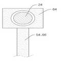
도 1 내지 도 4에는 베이스(10), 제1 마그넷(12), 마그넷열(14), 트레이(16), 제2 마그넷(18), 롤러부(20), 측벽(22), 샤프트(24), 이송롤러(26), 균형조절부(52), 제1 로드(54), 제2 로드(56), 균형바(58), 회전축(60), 힌지(62), 연결블록(64)이 도시되어 있다. 도 4에는 베이스(10), 제1 마그넷(12), 마그넷열(14), 트레이(16), 제2 마그넷(18), 롤러부(20), 측벽(22), 샤프트(24), 이송롤러(26), 가이드레일(36), 가이드블록(38)이 도시되어 있다. (같이 열거 할 것)
1 to 4, the
본 실시예에 따른 기판이송장치는, 기판의 이송을 위한 장치로서, 상기 기판의 이동방향을 따라 설치되는 베이스(10)와; 상기 기판의 이동방향을 따라 서로 이격되어 상기 베이스(10)에 결합되는 복수의 제1 마그넷(12)을 구비하는 마그넷열(14)과; 상기 베이스(10)를 따라 이동하며, 상기 기판이 안착되는 트레이(16)와; 상기 제1 마그넷(12)과 대향하도록 상기 트레이(16)에 결합되며, 상기 제1 마그넷(12)과 동일 극성을 갖는 제2 마그넷(18); 및 복수의 상기 제1 마그넷(12)에 각각 상응하며, 상기 트레이(16)를 이동시키는 복수의 롤러부(20)와; 상기 롤러부(20)와 상기 제1 마그넷(12) 사이에 개재되어 상기 롤러부(20)의 승강과 반대방향으로 상기 제1 마그넷(12)을 승강시키는 균형조절부(52)를 포함하여, 기판이송과정에서 트레이(16)의 하중에 의해 발생할 수 있는 기판이송장치의 손상을 방지하고, 롤러부(20)와 트레이(16)의 마찰에 의한 파티클의 발생을 감소시킬 수 있다.The substrate transfer apparatus according to the present embodiment includes an apparatus for transferring a substrate, the
베이스(10)는, 기판의 이동방향을 따라 설치된다. 기판은 평면형상을 가질 수 있으며, 베이스(10)의 폭은 평면형상 기판의 폭보다 넓게 제작될 수 있다. 베이스(10)는 기판의 이동방향을 따라 직선 또는 곡선형상으로 형성될 수 있다. 베이스(10)는 기판 처리공정을 수행하기 위해 충분한 길이를 가질 수 있다.The
베이스(10)는, 트레이(16) 양측단에 인접하여, 베이스(10)에서 연장되며, 트레이(16)의 이동을 가이드하는 한 쌍의 측벽(22)을 포함할 수 있다. 측벽(22)은 베이스(10)와 일체로 형성될 수 있으며, 트레이(16)가 베이스(10)를 따라 이동할 수 있도록 가이드할 수 있다. 한 쌍의 측벽(22)이 트레이(16)의 이동기준면의 높이보다 높게 베이스(10)에서 연장됨으로써, 트레이(16)가 베이스(10)로부터 이탈되는 것을 방지할 수 있다.The
마그넷열(14)은, 기판의 이동방향을 따라 서로 이격되어 베이스(10)에 결합되는 복수의 제1 마그넷(12)을 구비한다. 제1 마그넷(12)은 N극과 S극을 가지며, 양극 중 어느 하나의 극이 베이스(10) 일면에 노출되도록 결합될 수 있다. 제1 마그넷(12)은 높은 자력을 갖는 자성재료인 네오디뮴 자석, 사마륨 자석, 코발트 자석 또는 네오디뮴, 철, 붕소의 희토류 소결자석 등으로 구성될 수 있으며, 전자석일 수 있다. 베이스(10)에 노출되는 제1 마그넷(12)의 일단은 후술할 제2 마그넷(18)의 타단과 동일극성을 가진다. 따라서, 제1 마그넷(12)과 제2 마그넷(18) 사이에는 척력이 작용하며, 트레이(16)의 무게를 상쇄시킬 수 있다.The
트레이(16)는, 베이스(10)를 따라 이동하며, 기판이 안착된다. 트레이(16)는 기판의 폭보다 넓고, 베이스(10)의 폭보다 좁은 폭을 가질 수 있다. 트레이(16)는 후술할 롤러부(20)에 의하여 베이스(10)를 따라 이동하게 된다.The
제2 마그넷(18)은, 제1 마그넷(12)과 대향하도록 트레이(16)에 결합되며, 제1 마그넷(12)과 동일 극성을 갖는다. 제2 마그넷(18)은 N극과 S극을 가지며, 어느 하나의 극이 트레이(16) 일면에 노출되도록 결합될 수 있다. 제2 마그넷(18)은 제1 마그넷(12)과 동일한 소재의 자석일 수 있다. 트레이(16)의 일면에 노출되는 제2 마그넷(18)의 타단은 제1 마그넷(12)의 일단과 동일극성을 가진다. 따라서, 제1 마그넷(12)과 제2 마그넷(18) 사이에는 척력이 작용하며, 트레이(16)의 무게를 상쇄시킬 수 있다. The
베이스(10)에 결합되는 제1 마그넷(12)과 트레이(16)에 결합되는 제2 마그넷(18)은 서로 동일한 극성이 대향되도록 일부가 노출되어, 상호간에 척력이 발생하여, 트레이(16) 및 기판의 하중이 상쇄된 상태로 이동한다. 트레이(16)의 이동은 트레이(16)의 일단에 접한 롤러부(20)에 의하여 수행된다.The
롤러부(20)는, 제1 마그넷(12)에 각각 상응하며, 트레이(16)를 이동시킨다. 롤러부(20)는 일단이 트레이(16)에 접하며, 타단이 동력원에 연결되어, 동력원에서 공급되는 동력에 의해 트레이(16)를 이동시킬 수 있다. 롤러부(20)은 제1 마그넷(12)과 쌍을 이루게 되며, 서로 쌍을 이루는 롤러부(20)와 제1 마그네(12)에 후술할 균형조절부(52)가 개재된다.The
트레이(16)와 롤러부(20)의 접합부에서는, 트레이(16)의 무게로 인한 파티클이 발생할 수 있으나, 제1 마그넷(12)과 제2 마그넷(18) 사이에서 작용하는 척력에 의하여 트레이(16)의 무게를 일부 상쇄시킴으로써, 마찰력이 감소되어 파티클의 발생을 감소시킬 수 있다. 또한, 트레이(16)의 무게로 인한 롤러부(20)의 변형도 상기한 척력에 의하여 방지할 수 있다.Particles may be generated due to the weight of the
롤러부(20)는, 상기 측벽(22)을 관통하는 샤프트(24)와 상기 샤프트(24)의 일단에 결합되며 상기 트레이(16)에 접하는 이송롤러(26)를 포함할 수 있다. 샤프트(24)는 베이스(10)에 형성되는 측벽(22)을 관통하며, 샤프트(24)의 직경은 측벽(22)에 형성되는 관통공의 내경보다 작다. 따라서, 측벽(22)은 샤프트(24)의 회전에 영향을 주지 않는다.The
이송롤러(26)는 샤프트(24)의 일단에 결합되며, 트레이(16)에 접한다. 후술하는 모터의 회전에 의하여 샤프트(24) 및 이송롤러(26)가 회전하게 되며, 이송롤러(26)의 회전에 의하여 트레이(16)가 베이스(10)를 따라 이동할 수 있다. 이송롤러(26)는 트레이(16)에 접하기 때문에, 트레이(16)와 마찰되며, 마찰에 의하여 파티클이 발생할 수 있으나, 제1 마그넷(12)과 제2 마그넷(18) 사이의 척력에 의하여 트레이(16)의 하중이 상쇄되므로, 파티클의 발생을 줄일 수 있다.The conveying roller 26 is coupled to one end of the
트레이(16)에 기판을 안착시키면, 기판과 트레이(16)의 하중은 롤러부(20)와 두 마그넷과의 척력에 의해 지지되는데, 본 실시예에 따른 기판이송장치는, 롤러부(20)와 마그넷에 작용하는 하중을 분배하기 위해 롤러부(20)와 제1 마그넷(12) 사이에 균형조절부(52)를 개재시킨 형태이다.When the substrate is seated on the
균형조절부(52)는, 롤러부(20)와 제1 마그넷(12) 사이에 개재되어, 롤러부(20)의 승강과 반대방향으로, 제1 마그넷(12)을 승강시켜 롤러부(20)와 마그넷에 작용하는 하중을 분배한다.The balance adjusting part 52 is interposed between the
본 실시예에 따른 균형조절부(52)는, 일단이 샤프트(24)에 결합되는 제1 로드(54)와, 상기 제1 로드(54)에 평행하게 배치되며 일단이 상기 제1 마그넷(12)에 결합되는 제2 로드(56) 및 중앙부가 회전축(60)에 회전가능하게 결합되며, 양단이 상기 제1 로드(54) 및 상기 제2 로드(56)의 타단에 힌지(62) 결합되는 균형바(58)를 포함한다.The balance adjusting unit 52 according to the present exemplary embodiment includes a first rod 54 having one end coupled to the
샤프트(24)와 제1 로드(54) 사이에는 연결블록(64)이 개재될 수 있다. 트레이(16)의 하중이 과중하지 않을 경우, 샤프트(24)는 연결블록(64)에 형성된 중공부를 관통하여, 제1 로드(54)에 지장없이 회전가능하며, 트레이(16)의 하중이 과중하여 샤프트(24)가 하강할 경우, 연결블록(64)와 접촉하여, 제1 로드(54)를 하강시킬 수 있다.The connecting
트레이(16)의 하중에 의하여, 롤러부(20)의 샤프트(24)가 하강할 수 있으며, 결국 샤프트(24)에 결합되는 제1 로드(54)가 하강한다. 제1 로드(54)의 하강으로 인하여 균형바(58)의 일단은 중앙부의 회전축(60)을 중심으로 하강되고 이에 따라 균형바(58)의 타단이 상승된다. 균형바(58)의 타단의 상승에 따라 균형바(58)의 타단에 힌지축(62)을 중심으로 힌지결합된 제2 로드(56)가 상승하면서 베이스(10)에 안착된 제1 마그넷(12)이 상승하게 된다.By the load of the
제1 마그넷(12)의 상승에 의하여, 척력이 작용하는 트레이(16)는 상승하게 되고, 상기 척력에 의하여 트레이(16)의 하중이 상쇄됨으로써 이송롤러(26)에 가해지는 하중이 감소되어 샤프트(24)가 상승하게 된다. 샤프트(24)의 상승에 따라 상기에 기술한 원리에 따라 제1 마그넷(12)이 하강하게 된다. 이와 같은 과정을 반복하여 롤러부(20)와 마그넷에 작용하는 하중을 분배하게 된다.The
본 변형예는 기판의 보다 정밀한 이송을 위한 것으로, 상술한 일 실시예에 따른 기판이송장치의 구성에 더하여, 베이스(10)에 기판의 이동방향을 따라 형성되는 가이드레일(36)을 형성하고, 트레이(16)에 가이드레일(36)에 의해 안내되는 가이드블록(38)을 형성한 형태이다.This modified example is for more precise transfer of the substrate, in addition to the configuration of the substrate transfer apparatus according to the above-described embodiment, to form a guide rail 36 formed along the moving direction of the substrate in the
구동부(20)의 작동에 따라 트레이(16)의 가이드블록(38)이 베이스(10)의 가이드레일(36)에 의해 가이드되어 보다 기판의 정밀한 이송이 가능하다.The guide block 38 of the
도 5는 본 발명의 다른 실시예에 따른 기판이송장치의 단면도이다. 도 5에는, 베이스(10), 제1 마그넷(12), 마그넷열(14), 트레이(16), 제2 마그넷(18), 롤러부(20), 측벽(22), 샤프트(24), 이송롤러(26), 연결블록(64), 제1 지지대(70), 제2 지지대(72), 제1 래크(74), 제2 래크(76), 피니언(78)이 도시되어 있다.5 is a cross-sectional view of a substrate transfer apparatus according to another embodiment of the present invention. 5, the
본 실시예에 따른 균형조절부(52)는, 일측이 상기 샤프트(24)에 결합되며 타측에 제1 래크(74)가 형성되는 제1 지지대(70)와; 일측이 상기 제1 마그넷(12)에 결합되며 타측에 제2 래크(76)가 형성되는 제2 지지대(72)와; 상기 제1 래크(74)와 상기 제2 래크(76)에 치합되며, 상기 제1 래크(74)와 상기 제2 래크(76) 사이에 개재되는 피니언(78)을 포함한다.The balance adjusting unit 52 according to the present embodiment includes: a first support 70 having one side coupled to the
제1 지지대(70)의 일단에는, 상기 샤프트(24)의 외경보다 큰 내경을 가지며, 상기 샤프트(24)에 의해 관통되는 연결블록(64)이 구비될 수 있다. 트레이(16)의 하중이 과중하지 않을 경우, 샤프트(24)는 연결블록(64)에 형성된 중공부를 관통하여, 제1 지지대(70)와 관계없이 회전가능하며, 트레이(16)의 하중이 과중하여 샤프트(24)가 하강할 경우, 연결블록(64)와 접촉하여, 제1 지지대(70)를 하강시킬 수 있다.At one end of the first support 70, a
트레이(16)의 하중에 의하여, 롤러부(20)의 샤프트(24)가 하강할 수 있으며, 일측이 샤프트(24)에 결합되는 제1 지지대(70)가 하강한다. 제1 지지대(70)의 하강으로 인하여, 제1 지지대(70)의 타측에 형성된 제1 래크(74)가 하강하고, 제1 래크(74)와 제2 래크(76) 사이에 치합된 피니언(78)의 회전에 의하여 제2 래크(76)는 상승한다. 제2 래크(76)의 상승으로 제2 지지대(72)가 상승하게 되며, 제2 지지대(72)의 일측과 연결되고, 베이스(10)에 배치된 제1 마그넷(12)이 상승하게 된다.By the load of the
제1 마그넷(12)의 상승에 의하여, 척력이 작용하는 트레이(16)는 상승하게 되고, 상기 척력에 의하여 트레이(16)의 하중이 상쇄됨으로써 이송롤러(26)에 가해지는 하중이 감소되어 샤프트(24)가 상승하게 된다. 샤프트(24)의 상승에 따라 상기에 기술한 원리에 따라, 제1 마그넷(12)이 하강하게 된다. 이와 같은 과정을 반복하여 롤러부(20)에 작용하는 하중을 분배하게 된다.The
전술한 실시예 외의 많은 실시예들이 본 발명의 특허청구범위 내에 존재한다.
Many embodiments other than the above-described embodiments are within the scope of the claims of the present invention.
10: 베이스12: 제1 마그넷
14: 마그넷열16: 트레이
18: 제2 마그넷20: 롤러부
22: 측벽24: 샤프트
26: 이송롤러36: 가이드레일
38: 가이드블록52: 균형조절부
54: 제1 로드56: 제2 로드
58: 균형바60: 회전축
62: 힌지64: 연결블록
70: 제1 지지대72: 제2 지지대
74: 제1 래크76: 제2 래크
78: 피니언10: Base 12: 1st magnet
14: Magnet column 16: Tray
18: 2nd magnet 20: Roller part
22: side wall 24: shaft
26: feed roller 36: guide rail
38: guide block 52: balance control unit
54: first load 56: second load
58: balance bar 60: rotating shaft
62: hinge 64: connecting block
70: first support 72: second support
74: first rack 76: second rack
78: pinion
Claims (7)
Translated fromKorean상기 기판의 이동방향을 따라 설치되는 베이스와;
상기 기판의 이동방향을 따라 서로 이격되어 상기 베이스에 결합되는 복수의 제1 마그넷을 구비하는 마그넷열과;
상기 베이스를 따라 이동하며, 상기 기판이 안착되는 트레이와;
상기 제1 마그넷과 대향하도록 상기 트레이에 결합되며, 상기 제1 마그넷과 동일 극성을 갖는 제2 마그넷; 및
복수의 상기 제1 마그넷에 각각 상응하며, 상기 트레이를 이동시키는 복수의 롤러부와;
상기 롤러부와 상기 제1 마그넷 사이에 개재되어 상기 롤러부의 승강과 반대방향으로 상기 제1 마그넷을 승강시키는 균형조절부를 포함하는, 기판이송장치.
An apparatus for transferring a substrate,
A base installed along the moving direction of the substrate;
A magnet array having a plurality of first magnets spaced apart from each other along the moving direction of the substrate and coupled to the base;
A tray moving along the base, on which the substrate is placed;
A second magnet coupled to the tray so as to face the first magnet and having the same polarity as the first magnet; And
A plurality of rollers respectively corresponding to the plurality of first magnets and moving the trays;
And a balance adjusting portion interposed between the roller portion and the first magnet to lift the first magnet in a direction opposite to that of the roller portion.
상기 베이스는,
상기 트레이의 양측단에 인접하여 상기 베이스에서 연장되며 상기 트레이의 이동을 가이드하는 한 쌍의 측벽을 포함하는 것을 특징으로 하는 기판이송장치.
The method of claim 1,
The base includes:
And a pair of side walls extending from the base adjacent to both ends of the tray and guiding movement of the tray.
상기 롤러부는,
상기 측벽을 관통하는 샤프트와;
상기 샤프트의 일단에 결합되며 상기 트레이에 접하는 이송롤러를 포함하며,
상기 균형조절부는,
일단이 상기 샤프트에 결합되는 제1 로드와;
상기 제1 로드에 평행하게 배치되며 일단이 상기 제1 마그넷에 결합되는 제2 로드와;
중앙부가 회전축에 회전가능하게 결합되며, 양단이 상기 제1 로드 및 상기 제2 로드의 타단에 힌지 결합되는 균형바를 포함하는 것을 특징으로 하는 기판이송장치.
3. The method of claim 2,
The roller unit
A shaft passing through the side wall;
And a conveying roller coupled to one end of the shaft and contacting the tray,
Wherein the balance adjuster comprises:
A first rod having one end coupled to the shaft;
A second rod disposed parallel to the first rod and having one end coupled to the first magnet;
And a balance bar rotatably coupled to the rotary shaft at a central portion thereof and hinged to both ends of the first rod and the second rod at both ends thereof.
상기 제1 로드의 일단에는, 상기 샤프트의 외경보다 큰 내경을 가지며, 상기 샤프트에 의해 관통되는 연결블록이 구비되는 것을 특징으로 하는 기판이송장치.
The method of claim 3,
One end of the first rod, the substrate transport apparatus having an inner diameter larger than the outer diameter of the shaft, the connecting block penetrated by the shaft is provided.
상기 롤러부는,
상기 측벽을 관통하는 샤프트와;
상기 샤프트의 일단에 결합되며 상기 트레이에 접하는 이송롤러를 포함하며,
상기 균형조절부는,
일측이 상기 샤프트에 결합되며 타측에 제1 래크가 형성되는 제1 지지대와;
일측이 상기 제1 마그넷에 결합되며 타측에 제2 래크가 형성되는 제2 지지대와;
상기 제1 래크와 상기 제2 래크에 치합되며, 상기 제1 래크와 상기 제2 래크사이에 개재되는 피니언을 포함하는 것을 특징으로 하는 기판이송장치.
3. The method of claim 2,
The roller unit
A shaft passing through the side wall;
And a conveying roller coupled to one end of the shaft and contacting the tray,
Wherein the balance adjuster comprises:
A first support having one side coupled to the shaft and having a first rack formed at the other side;
A second support having one side coupled to the first magnet and having a second rack formed at the other side;
And a pinion meshed with the first rack and the second rack and interposed between the first rack and the second rack.
상기 제1 지지대의 일단에는, 상기 샤프트의 외경보다 큰 내경을 가지며, 상기 샤프트에 의해 관통되는 연결블록이 구비되는 것을 특징으로 하는 기판이송장치.
The method of claim 5,
One end of the first support, the substrate transport apparatus having an inner diameter larger than the outer diameter of the shaft, characterized in that the connection block penetrated by the shaft is provided.
상기 베이스에는, 상기 기판의 이동방향을 따라 형성되는 가이드레일이 형성되며,
상기 트레이에는, 상기 가이드레일에 의해 안내되는 가이드블록이 형성되는 것을 것을 특징으로 하는 기판이송장치.The method of claim 1,
Wherein a guide rail is formed on the base along a moving direction of the substrate,
The tray, the substrate transport apparatus characterized in that the guide block guided by the guide rail is formed.
Priority Applications (1)
| Application Number | Priority Date | Filing Date | Title |
|---|---|---|---|
| KR1020120106111AKR101328574B1 (en) | 2012-09-24 | 2012-09-24 | Apparatus for transferring substrate |
Applications Claiming Priority (1)
| Application Number | Priority Date | Filing Date | Title |
|---|---|---|---|
| KR1020120106111AKR101328574B1 (en) | 2012-09-24 | 2012-09-24 | Apparatus for transferring substrate |
Publications (1)
| Publication Number | Publication Date |
|---|---|
| KR101328574B1true KR101328574B1 (en) | 2013-11-13 |
Family
ID=49857576
Family Applications (1)
| Application Number | Title | Priority Date | Filing Date |
|---|---|---|---|
| KR1020120106111AExpired - Fee RelatedKR101328574B1 (en) | 2012-09-24 | 2012-09-24 | Apparatus for transferring substrate |
Country Status (1)
| Country | Link |
|---|---|
| KR (1) | KR101328574B1 (en) |
Cited By (5)
| Publication number | Priority date | Publication date | Assignee | Title |
|---|---|---|---|---|
| CN109484794A (en)* | 2017-09-13 | 2019-03-19 | 京东方科技集团股份有限公司 | A kind of base plate transfer device |
| KR102168407B1 (en)* | 2019-07-19 | 2020-10-21 | 주식회사 에스에프에이 | Glass transfer apparatus |
| KR102169294B1 (en)* | 2019-07-19 | 2020-10-23 | 주식회사 에스에프에이 | Glass deposition apparatus |
| CN115335977A (en)* | 2020-03-20 | 2022-11-11 | 应用材料公司 | Substrate tray transfer system for substrate handling equipment |
| KR20230054559A (en)* | 2021-10-15 | 2023-04-25 | 송은희 | Fatigue and reliability test module that is easy to detach and combine |
Citations (2)
| Publication number | Priority date | Publication date | Assignee | Title |
|---|---|---|---|---|
| JPH07115120A (en)* | 1993-10-18 | 1995-05-02 | Hitachi Ltd | Substrate transfer apparatus and method thereof |
| KR20110091131A (en)* | 2010-02-05 | 2011-08-11 | 주식회사 에스에프에이 | Conveyer |
- 2012
- 2012-09-24KRKR1020120106111Apatent/KR101328574B1/ennot_activeExpired - Fee Related
Patent Citations (2)
| Publication number | Priority date | Publication date | Assignee | Title |
|---|---|---|---|---|
| JPH07115120A (en)* | 1993-10-18 | 1995-05-02 | Hitachi Ltd | Substrate transfer apparatus and method thereof |
| KR20110091131A (en)* | 2010-02-05 | 2011-08-11 | 주식회사 에스에프에이 | Conveyer |
Cited By (7)
| Publication number | Priority date | Publication date | Assignee | Title |
|---|---|---|---|---|
| CN109484794A (en)* | 2017-09-13 | 2019-03-19 | 京东方科技集团股份有限公司 | A kind of base plate transfer device |
| US11230436B2 (en) | 2017-09-13 | 2022-01-25 | Boe Technology Group Co., Ltd. | Substrate conveyance device |
| KR102168407B1 (en)* | 2019-07-19 | 2020-10-21 | 주식회사 에스에프에이 | Glass transfer apparatus |
| KR102169294B1 (en)* | 2019-07-19 | 2020-10-23 | 주식회사 에스에프에이 | Glass deposition apparatus |
| CN115335977A (en)* | 2020-03-20 | 2022-11-11 | 应用材料公司 | Substrate tray transfer system for substrate handling equipment |
| KR20230054559A (en)* | 2021-10-15 | 2023-04-25 | 송은희 | Fatigue and reliability test module that is easy to detach and combine |
| KR102678331B1 (en) | 2021-10-15 | 2024-06-25 | 송은희 | Fatigue and reliability test module that is easy to detach and combine |
Similar Documents
| Publication | Publication Date | Title |
|---|---|---|
| KR101328574B1 (en) | Apparatus for transferring substrate | |
| CN101948047B (en) | Hydraulic electromagnetic steel plate pre-stacking device | |
| JP5152469B2 (en) | Substrate transfer device | |
| JP6140468B2 (en) | Conveyor direction change device | |
| KR101278295B1 (en) | Lifting apparatus | |
| JP2008081297A (en) | Stacker crane | |
| KR20140036086A (en) | Plasma processing apparatus | |
| KR102279408B1 (en) | Transfer robot with multi arm | |
| JP4711770B2 (en) | Conveying apparatus, vacuum processing apparatus, and conveying method | |
| KR101419355B1 (en) | Loading and exchanging system of large mask frame and method thereof | |
| JP2012250809A (en) | Transfer device and conveyer device | |
| CN114655614A (en) | Automatic loading and unloading equipment | |
| KR102068000B1 (en) | Substrate Loading Device for Deposition Apparatus | |
| KR101587337B1 (en) | Lifting apparatus and apparatus for transferring substrate comprising the same | |
| CN109019028A (en) | Base plate transmission device | |
| KR20120050108A (en) | Non-contact moving apparatus of floating table using magnet | |
| CN108726143A (en) | A kind of steering conveying equipment | |
| CN110466934B (en) | Jacking transfer machine | |
| KR101099531B1 (en) | Substrate transfer module and substrate processing apparatus including same | |
| JP4711771B2 (en) | Conveying device and vacuum processing device | |
| CN106062944A (en) | Lifting device for substrate conveying device and substrate conveying device | |
| JP5914022B2 (en) | Mechanical parking equipment | |
| KR101580390B1 (en) | Rotating apparatus and apparatus for transferring substrate comprising the same | |
| KR20160121752A (en) | Transfer robot with multi arm | |
| KR20160135450A (en) | Apparatus for transferring a vehicle |
Legal Events
| Date | Code | Title | Description |
|---|---|---|---|
| A201 | Request for examination | ||
| PA0109 | Patent application | St.27 status event code:A-0-1-A10-A12-nap-PA0109 | |
| PA0201 | Request for examination | St.27 status event code:A-1-2-D10-D11-exm-PA0201 | |
| E701 | Decision to grant or registration of patent right | ||
| PE0701 | Decision of registration | St.27 status event code:A-1-2-D10-D22-exm-PE0701 | |
| GRNT | Written decision to grant | ||
| PR0701 | Registration of establishment | St.27 status event code:A-2-4-F10-F11-exm-PR0701 | |
| PR1002 | Payment of registration fee | St.27 status event code:A-2-2-U10-U11-oth-PR1002 Fee payment year number:1 | |
| PG1601 | Publication of registration | St.27 status event code:A-4-4-Q10-Q13-nap-PG1601 | |
| PN2301 | Change of applicant | St.27 status event code:A-5-5-R10-R13-asn-PN2301 St.27 status event code:A-5-5-R10-R11-asn-PN2301 | |
| R18-X000 | Changes to party contact information recorded | St.27 status event code:A-5-5-R10-R18-oth-X000 | |
| FPAY | Annual fee payment | Payment date:20160927 Year of fee payment:4 | |
| PR1001 | Payment of annual fee | St.27 status event code:A-4-4-U10-U11-oth-PR1001 Fee payment year number:4 | |
| PR1001 | Payment of annual fee | St.27 status event code:A-4-4-U10-U11-oth-PR1001 Fee payment year number:5 | |
| FPAY | Annual fee payment | Payment date:20181107 Year of fee payment:6 | |
| PR1001 | Payment of annual fee | St.27 status event code:A-4-4-U10-U11-oth-PR1001 Fee payment year number:6 | |
| PR1001 | Payment of annual fee | St.27 status event code:A-4-4-U10-U11-oth-PR1001 Fee payment year number:7 | |
| PR1001 | Payment of annual fee | St.27 status event code:A-4-4-U10-U11-oth-PR1001 Fee payment year number:8 | |
| PR1001 | Payment of annual fee | St.27 status event code:A-4-4-U10-U11-oth-PR1001 Fee payment year number:9 | |
| PR1001 | Payment of annual fee | St.27 status event code:A-4-4-U10-U11-oth-PR1001 Fee payment year number:10 | |
| PR1001 | Payment of annual fee | St.27 status event code:A-4-4-U10-U11-oth-PR1001 Fee payment year number:11 | |
| PC1903 | Unpaid annual fee | St.27 status event code:A-4-4-U10-U13-oth-PC1903 Not in force date:20241107 Payment event data comment text:Termination Category : DEFAULT_OF_REGISTRATION_FEE | |
| PC1903 | Unpaid annual fee | St.27 status event code:N-4-6-H10-H13-oth-PC1903 Ip right cessation event data comment text:Termination Category : DEFAULT_OF_REGISTRATION_FEE Not in force date:20241107 |