KR101325794B1 - Lyquid crystal panel assembly and lyquid crystal display having the same - Google Patents
Lyquid crystal panel assembly and lyquid crystal display having the sameDownload PDFInfo
- Publication number
- KR101325794B1 KR101325794B1KR1020100066978AKR20100066978AKR101325794B1KR 101325794 B1KR101325794 B1KR 101325794B1KR 1020100066978 AKR1020100066978 AKR 1020100066978AKR 20100066978 AKR20100066978 AKR 20100066978AKR 101325794 B1KR101325794 B1KR 101325794B1
- Authority
- KR
- South Korea
- Prior art keywords
- liquid crystal
- crystal panel
- disposed
- light source
- housing
- Prior art date
- Legal status (The legal status is an assumption and is not a legal conclusion. Google has not performed a legal analysis and makes no representation as to the accuracy of the status listed.)
- Active
Links
Images


Classifications
- G—PHYSICS
- G02—OPTICS
- G02F—OPTICAL DEVICES OR ARRANGEMENTS FOR THE CONTROL OF LIGHT BY MODIFICATION OF THE OPTICAL PROPERTIES OF THE MEDIA OF THE ELEMENTS INVOLVED THEREIN; NON-LINEAR OPTICS; FREQUENCY-CHANGING OF LIGHT; OPTICAL LOGIC ELEMENTS; OPTICAL ANALOGUE/DIGITAL CONVERTERS
- G02F1/00—Devices or arrangements for the control of the intensity, colour, phase, polarisation or direction of light arriving from an independent light source, e.g. switching, gating or modulating; Non-linear optics
- G02F1/01—Devices or arrangements for the control of the intensity, colour, phase, polarisation or direction of light arriving from an independent light source, e.g. switching, gating or modulating; Non-linear optics for the control of the intensity, phase, polarisation or colour
- G02F1/13—Devices or arrangements for the control of the intensity, colour, phase, polarisation or direction of light arriving from an independent light source, e.g. switching, gating or modulating; Non-linear optics for the control of the intensity, phase, polarisation or colour based on liquid crystals, e.g. single liquid crystal display cells
- G02F1/133—Constructional arrangements; Operation of liquid crystal cells; Circuit arrangements
- G02F1/1333—Constructional arrangements; Manufacturing methods
- G02F1/133308—Support structures for LCD panels, e.g. frames or bezels
- G—PHYSICS
- G02—OPTICS
- G02B—OPTICAL ELEMENTS, SYSTEMS OR APPARATUS
- G02B6/00—Light guides; Structural details of arrangements comprising light guides and other optical elements, e.g. couplings
- G02B6/0001—Light guides; Structural details of arrangements comprising light guides and other optical elements, e.g. couplings specially adapted for lighting devices or systems
- G02B6/0011—Light guides; Structural details of arrangements comprising light guides and other optical elements, e.g. couplings specially adapted for lighting devices or systems the light guides being planar or of plate-like form
- G02B6/0066—Light guides; Structural details of arrangements comprising light guides and other optical elements, e.g. couplings specially adapted for lighting devices or systems the light guides being planar or of plate-like form characterised by the light source being coupled to the light guide
- G02B6/0073—Light emitting diode [LED]
- G—PHYSICS
- G02—OPTICS
- G02B—OPTICAL ELEMENTS, SYSTEMS OR APPARATUS
- G02B6/00—Light guides; Structural details of arrangements comprising light guides and other optical elements, e.g. couplings
- G02B6/0001—Light guides; Structural details of arrangements comprising light guides and other optical elements, e.g. couplings specially adapted for lighting devices or systems
- G02B6/0011—Light guides; Structural details of arrangements comprising light guides and other optical elements, e.g. couplings specially adapted for lighting devices or systems the light guides being planar or of plate-like form
- G02B6/0081—Mechanical or electrical aspects of the light guide and light source in the lighting device peculiar to the adaptation to planar light guides, e.g. concerning packaging
- G02B6/0083—Details of electrical connections of light sources to drivers, circuit boards, or the like
- G—PHYSICS
- G02—OPTICS
- G02B—OPTICAL ELEMENTS, SYSTEMS OR APPARATUS
- G02B6/00—Light guides; Structural details of arrangements comprising light guides and other optical elements, e.g. couplings
- G02B6/0001—Light guides; Structural details of arrangements comprising light guides and other optical elements, e.g. couplings specially adapted for lighting devices or systems
- G02B6/0011—Light guides; Structural details of arrangements comprising light guides and other optical elements, e.g. couplings specially adapted for lighting devices or systems the light guides being planar or of plate-like form
- G02B6/0081—Mechanical or electrical aspects of the light guide and light source in the lighting device peculiar to the adaptation to planar light guides, e.g. concerning packaging
- G02B6/0085—Means for removing heat created by the light source from the package
- G—PHYSICS
- G02—OPTICS
- G02F—OPTICAL DEVICES OR ARRANGEMENTS FOR THE CONTROL OF LIGHT BY MODIFICATION OF THE OPTICAL PROPERTIES OF THE MEDIA OF THE ELEMENTS INVOLVED THEREIN; NON-LINEAR OPTICS; FREQUENCY-CHANGING OF LIGHT; OPTICAL LOGIC ELEMENTS; OPTICAL ANALOGUE/DIGITAL CONVERTERS
- G02F1/00—Devices or arrangements for the control of the intensity, colour, phase, polarisation or direction of light arriving from an independent light source, e.g. switching, gating or modulating; Non-linear optics
- G02F1/01—Devices or arrangements for the control of the intensity, colour, phase, polarisation or direction of light arriving from an independent light source, e.g. switching, gating or modulating; Non-linear optics for the control of the intensity, phase, polarisation or colour
- G02F1/13—Devices or arrangements for the control of the intensity, colour, phase, polarisation or direction of light arriving from an independent light source, e.g. switching, gating or modulating; Non-linear optics for the control of the intensity, phase, polarisation or colour based on liquid crystals, e.g. single liquid crystal display cells
- G02F1/133—Constructional arrangements; Operation of liquid crystal cells; Circuit arrangements
- G02F1/1333—Constructional arrangements; Manufacturing methods
- G02F1/133308—Support structures for LCD panels, e.g. frames or bezels
- G02F1/133314—Back frames
- G—PHYSICS
- G02—OPTICS
- G02F—OPTICAL DEVICES OR ARRANGEMENTS FOR THE CONTROL OF LIGHT BY MODIFICATION OF THE OPTICAL PROPERTIES OF THE MEDIA OF THE ELEMENTS INVOLVED THEREIN; NON-LINEAR OPTICS; FREQUENCY-CHANGING OF LIGHT; OPTICAL LOGIC ELEMENTS; OPTICAL ANALOGUE/DIGITAL CONVERTERS
- G02F1/00—Devices or arrangements for the control of the intensity, colour, phase, polarisation or direction of light arriving from an independent light source, e.g. switching, gating or modulating; Non-linear optics
- G02F1/01—Devices or arrangements for the control of the intensity, colour, phase, polarisation or direction of light arriving from an independent light source, e.g. switching, gating or modulating; Non-linear optics for the control of the intensity, phase, polarisation or colour
- G02F1/13—Devices or arrangements for the control of the intensity, colour, phase, polarisation or direction of light arriving from an independent light source, e.g. switching, gating or modulating; Non-linear optics for the control of the intensity, phase, polarisation or colour based on liquid crystals, e.g. single liquid crystal display cells
- G02F1/133—Constructional arrangements; Operation of liquid crystal cells; Circuit arrangements
- G02F1/1333—Constructional arrangements; Manufacturing methods
- G02F1/133308—Support structures for LCD panels, e.g. frames or bezels
- G02F1/133317—Intermediate frames, e.g. between backlight housing and front frame
Landscapes
- Physics & Mathematics (AREA)
- General Physics & Mathematics (AREA)
- Optics & Photonics (AREA)
- Nonlinear Science (AREA)
- Liquid Crystal (AREA)
- Mathematical Physics (AREA)
- Chemical & Material Sciences (AREA)
- Crystallography & Structural Chemistry (AREA)
- Engineering & Computer Science (AREA)
- Microelectronics & Electronic Packaging (AREA)
Abstract
Translated fromKoreanDescription
Translated fromKorean본 발명은 LED광원을 이용한 액정표시장치에 관한 것이다.The present invention relates to a liquid crystal display using the LED light source.
일반적으로, 액정표시장치는 인가전압에 따른 액정의 투과도의 변화를 이용하여 각종 장치에서 발생되는 여러가지 전기적인 정보를 시각정보로 변화시켜 전달하는 장치로서, CRT와는 달리 자기발광성이 없어 후광이 필요하지만 동작 전압이 낮아 소비 전력이 적고, 휴대용으로 쓰일 수 있어 손목시계, TV, 컴퓨터용 모니터 등에 널리 쓰이고 있는 평판 디스플레이의 일종이다.In general, a liquid crystal display device is a device for changing and transmitting various electrical information generated by various devices into visual information by using a change in transmittance of liquid crystal according to an applied voltage. It is a kind of flat panel display that is widely used in watches, TVs, and computer monitors because it has low power consumption and low power consumption.
이러한 액정표시장치는 액정패널과, 이 액정패널에 인접하여 배치된 백라이트모듈(후광장치)를 포함한다.Such a liquid crystal display device includes a liquid crystal panel and a backlight module (backlight device) disposed adjacent to the liquid crystal panel.
액정패널은 미세간격으로 이격되어 설치된 한 쌍의 기판, 기판과 기판 사이의 이격공간에 밀봉적으로 배치된 액정, 이 액정을 구동시키는 구동회로를 가진다.The liquid crystal panel has a pair of substrates spaced apart at fine intervals, liquid crystals arranged in a sealing space between the substrates and the substrates, and a driving circuit for driving the liquid crystals.
이 액정패널은 액정의 구동방식에 따라, 스위치소자에 의해 화소용량을 구동시키는 능동매트릭스(active matrix)방식, 스위치소자를 이용하지 않고 화소용량을 구동시키는 수동매트릭스(passive matirx) 방식 등으로 구분된다.The liquid crystal panel is classified into an active matrix method for driving pixel capacitance by a switch element, and a passive matirx method for driving pixel capacitance without using a switch element, according to a liquid crystal driving method. .
특히, 능동매트릭스 방식은 박막트랜지스터(TFT : Thin Film Transistor) 등의 3단자형 스위치소자를 이용하는 형태, 박막다이오드(TFD : Thin Film Diode) 등의 2단자형 스위치소자를 이용하는 형태 등으로 구분될 수 있다.In particular, the active matrix method may be classified into a type using a three-terminal switch element such as a thin film transistor (TFT), or a type using a two-terminal switch element such as a thin film diode (TFD). have.
그리고, 백라이트모듈은 액정패널에 인접하여 배치된 도광판, 이 도광판에 빛을 조사하는 광원을 포함하며, 이 광원으로부터 도광판으로 전달된 빛은 확산판 및/또는 프리즘 등을 통해 액정패널 측으로 유도된다.The backlight module includes a light guide plate disposed adjacent to the liquid crystal panel and a light source for irradiating light to the light guide plate, and the light transmitted from the light source to the light guide plate is guided to the liquid crystal panel through a diffusion plate and / or a prism.
한편, 이러한 백라이트모듈의 광원에는, 냉음극형광램프(CCFL, Cold Cathode Fluorescent Lamp) 또는 외부전극형광램프(EEFL, External Electrode Fluorescent Lamp) 등과 같은 형광램프류가 주로 이용되었지만, 이러한 형광램프류는 플라즈마의 가스 압력이 변화함에 따라 수명이 짧아지고, 플라즈마 방전에 필요한 수백 볼트의 높은 동작전압을 구현하기 위한 인버터 등이 요구될 뿐만 아니라, 전력소비효율이 낮은 단점 등이 있었다.On the other hand, as the light source of the backlight module, fluorescent lamps such as Cold Cathode Fluorescent Lamps (CCFLs) or External Electrode Fluorescent Lamps (EEFLs) are mainly used. As the pressure changes, the service life is shortened, and an inverter for implementing a high operating voltage of several hundred volts required for plasma discharge is required, and power consumption efficiency is low.
이에 따라, 최근에는 백라이트모듈의 광원으로 발광다이오드소자(이하에서는 LED라 통칭함)가 각광받고 있다. 이 LED는 반도체에 전압을 가할 때 생기는 발광현상을 이용하여 빛을 발생시키는 발광소자로서, 종래의 광원에 비해 소형이고, 수명이 길며, 전기에너지가 빛에너지로 직접 변환되기 때문에 그 에너지효율이 높음과 동시에 낮은 동작전압을 가지는 장점이 있다.Accordingly, in recent years, light emitting diode elements (hereinafter referred to as LEDs) have been in the spotlight as light sources of backlight modules. This LED is a light emitting device that generates light by using the light emitting phenomenon generated when voltage is applied to the semiconductor. It is small in size, longer in life, and has high energy efficiency because electric energy is directly converted into light energy. At the same time, there is an advantage of having a low operating voltage.
하지만, 이러한 LED를 백라이트모듈의 광원으로 이용하는 액정표시장치는 LED의 발광작동시에 매우 높은 열이 발생하여 액정패널에 나쁜 영향을 끼칠 수 있고, 또한 그 고열로 인해 LED 자체의 발광성능이 저하된다. 이에 따라 최근에는 LED광원의 열발산을 보다 효율적으로 수행하기 위한 다양한 형태의 열발산구조가 개시되어 있다.However, a liquid crystal display device using such an LED as a light source of a backlight module may generate a very high heat during the light emitting operation of the LED, which may adversely affect the liquid crystal panel, and the high heat may deteriorate the light emitting performance of the LED itself. . Accordingly, recently, various types of heat dissipation structures for more efficiently performing heat dissipation of LED light sources have been disclosed.
도 1은 LED광원을 이용한 액정표시장치의 일예를 도시한 측단면도이다.1 is a side cross-sectional view showing an example of a liquid crystal display device using an LED light source.
도시된 바와 같이, 종래의 액정표시장치는 액정패널(1), 액정패널(1)로 빛을 조사하는 백라이트모듈(2), 액정패널(1) 및 백라이트모듈(2)을 구동시키는 제어부(3), 및 액정패널(1) 및 백라이트모듈(2)이 장착된 프레임(4)을 포함한다.As shown, a conventional liquid crystal display device includes a liquid crystal panel 1, a
액정패널(1)에는 액정용 구동회로기판(미도시)이 접속되어 있다.A liquid crystal drive circuit board (not shown) is connected to the liquid crystal panel 1.
백라이트모듈(2)은 LED광원부(5)를 포함하고, 이 LED광원부(5)는 복수의 LED(5a)와 이 복수의 LED(5a)가 실장된 회로기판(5b)으로 이루어진다.The
이 LED광원부(5)의 후면에는 다수의 방열핀(7a)을 구비한 방열부재(7)가 설치되고, 이 방열부재(7)를 통해 LED광원부(5)에서 발생한 열을 발산시킨다.On the rear surface of the LED
제어부(3)는 전원공급장치, 인버터, 주제어기판, 각종 전기소자 및 센서류 등으로 이루어져, 액정표시장치의 전체 작동을 제어 및 구동시킨다.The
프레임(4)은 액정패널(1)이 장착되는 전면프레임(4a) 및 이 전면프레임(4a)의 후면에 배치되는 후면프레임(4b)로 이루어진다.The
그리고, 프레임(4)과 백라이트모듈(2) 사이에는 백라이트모듈(2) 및 액정패널(1)을 감싸는 제1실드부(8) 및 제어부(3)를 감싸는 제2실드부(9)가 배치된다.In addition, a
이러한 제1 및 제2실드부(8, 9)는 전기 전도성 재질로 이루어져, 백라이트모듈(2) 및 제어부(3)에서 발생하는 각종 전자파를 차폐한다.The first and
하지만, 이러한 종래기술에 따른 액정표시장치는 LED광원부(5)에서 발생하는 고열을 발산시키기 위한 방열부재(7)가 설치공간을 많이 차지함에 따라, 액정표시장치의 전체 크기를 증대시키는 단점이 있었다.However, the liquid crystal display device according to the related art has a drawback of increasing the overall size of the liquid crystal display device as the
또한, 종래의 액정표시장치는 제어부(3)에서 발생하는 각종 고열을 발산시키기 위한 방열구조가 구비되지 않아 제어부(3)에서 발생하는 고열로 인해 액정표시장치의 표시품질이 저하될 수 있는 단점이 있었다.In addition, the conventional liquid crystal display device is not provided with a heat dissipation structure for dissipating various high heat generated in the
그리고, 종래의 액정표시장치는 제1 및 제2 실드부(8, 9)와 같이 백라이트모듈(2) 및 액정패널(1)에서 발생하는 전자파를 차폐하기 위한 차폐구조가 설치됨에 따라 조립부품 및 조립공수를 증대시키고, 이로 인해 전체 부피를 크게 하는 단점이 있었다.In the conventional liquid crystal display device, as the first and
본 발명은 상기와 같은 점을 감안하여 안출한 것으로, 보다 컴팩트한 크기를 구현할 수 있는 액정패널조립체 및 액정표시장치를 제공하는 데 그 목적이 있다.The present invention has been made in view of the above, and an object thereof is to provide a liquid crystal panel assembly and a liquid crystal display device capable of realizing a more compact size.
또한, 본 발명은 표시품질(disply quality)를 대폭 향상시킨 액정패널조립체 및 액정표시장치를 제공하는 데 그 목적이 있다.In addition, an object of the present invention is to provide a liquid crystal panel assembly and a liquid crystal display device which greatly improved the display quality (disply quality).
또한, 본 발명은 높은 에너지 효율을 구현할 수 있는 액정패널조립체 및 액정표시장치를 제공하는 데 그 목적이 있다.In addition, an object of the present invention is to provide a liquid crystal panel assembly and a liquid crystal display device that can implement a high energy efficiency.
그리고, 본 발명은 백라이트모듈의 LED광원에서 발생하는 높은 고열을 보다 효과적으로 방출시킬 수 있는 액정패널조립체 및 액정표시장치를 제공하는 데 그 목적이 있다.In addition, an object of the present invention is to provide a liquid crystal panel assembly and a liquid crystal display device that can more effectively emit a high heat generated in the LED light source of the backlight module.
상기와 같은 목적을 달성하기 위한 본 발명의 일 실시예에 따른 액정패널조립체는,Liquid crystal panel assembly according to an embodiment of the present invention for achieving the above object,
액정패널;A liquid crystal panel;
액정패널에 빛을 조사하는 LED광원부를 가진 백라이트 모듈; 및A backlight module having an LED light source for irradiating light to the liquid crystal panel; And
액정패널 및 백라이트모듈을 감싸는 하우징;을 포함하고,It includes; a housing surrounding the liquid crystal panel and the backlight module;
LED광원부와 인접하는 하우징은 열전도성 재질로 이루어진 것을 특징으로 한다.The housing adjacent to the LED light source portion is characterized in that made of a thermally conductive material.
상기 하우징은 액정패널의 화면이 노출되는 전면하우징 및 백라이트모듈의 후면에 배치되는 후면하우징을 포함하고, 후면하우징은 열전도성재질로 이루어진다.The housing includes a front housing where the screen of the liquid crystal panel is exposed and a rear housing disposed at the rear of the backlight module, and the rear housing is made of a thermally conductive material.
상기 후면하우징은 LED광원부를 감싸도록 배치된다.The rear housing is disposed to surround the LED light source.
상기 백라이트 모듈은,The backlight module,
적어도 하나의 LED광원부;At least one LED light source unit;
상기 LED광원부에서의 빛을 안내하는 도광판;A light guide plate for guiding light from the LED light source;
상기 도광판의 빛을 액정패널로 확산시키는 확산판; 및A diffusion plate for diffusing the light of the light guide plate into the liquid crystal panel; And
상기 도광판의 빛을 확산판으로 반사시키는 반사판;을 포함한다.It includes a; reflecting plate for reflecting the light of the light guide plate to the diffusion plate.
상기 백라이트 모듈은, 상기 도광판의 양측면에 상호 대칭적으로 배치된 한 쌍의 LED광원부를 포함한다.The backlight module includes a pair of LED light source parts disposed symmetrically on both side surfaces of the light guide plate.
본 발명의 일 실시예에 따른 액정표시장치는,According to an embodiment of the present invention,
액정패널 및 액정패널에 빛을 조사하는 LED광원부를 가진 백라이트 모듈을 구비한 액정패널조립체; 및A liquid crystal panel assembly having a liquid crystal panel and a backlight module having an LED light source for irradiating light to the liquid crystal panel; And
액정패널조립체가 장착되는 프레임;을 포함하고,And a frame on which the liquid crystal panel assembly is mounted.
LED광원부와 인접하는 상기 프레임의 일부는 열전도성 재질로 이루어진다.Part of the frame adjacent to the LED light source portion is made of a thermally conductive material.
상기 프레임은 액정패널의 표시화면이 노출되는 전면프레임; 및The frame includes a front frame to which the display screen of the liquid crystal panel is exposed; And
상기 전면 프레임의 후방에 장착되는 후면프레임;을 포함하고,And a rear frame mounted to the rear of the front frame.
상기 후면프레임은 열전도성 재질로 이루어진다.The rear frame is made of a thermally conductive material.
상기 후면프레임은 열 및 전기 전도성재질로 이루어진다.The rear frame is made of a thermally and electrically conductive material.
상기 액정패널조립체는 액정패널 및 백라이트모듈을 감싸는 하우징;을 더 포함하고, 상기 LED광원부와 인접하는 하우징은 열전도성 재질로 이루어진다.The liquid crystal panel assembly further includes a housing surrounding the liquid crystal panel and the backlight module, and the housing adjacent to the LED light source part is made of a thermally conductive material.
상기 하우징은 상기 액정패널의 화면이 노출되는 전면하우징 및 상기 백라이트모듈의 후면에 배치되는 후면하우징을 포함하고, 상기 후면하우징은 열전도성재질로 이루어진다.The housing includes a front housing to which the screen of the liquid crystal panel is exposed and a rear housing disposed at the rear of the backlight module, and the rear housing is made of a thermally conductive material.
상기 후면하우징은 상기 LED광원부를 감싸도록 배치된다.The rear housing is arranged to surround the LED light source.
상기 후면하우징은 상기 프레임과 접촉한다.The rear housing is in contact with the frame.
본 발명의 다른 실시예에 따른 액정표시장치는,According to another embodiment of the present invention,
액정패널 및 상기 액정패널에 빛을 조사하는 LED광원부를 가진 백라이트 모듈을 구비한 액정패널조립체; 및 A liquid crystal panel assembly having a liquid crystal panel and a backlight module having an LED light source unit emitting light to the liquid crystal panel; And
상기 액정패널조립체가 장착되고, 열전도성 재질로 이루어진 프레임;을 포함한다.And a frame on which the liquid crystal panel assembly is mounted and made of a thermally conductive material.
도 1은 종래의 액정표시장치를 도시한 도면.
도 2는 본 발명의 일 실시예에 따른 액정패널조립체를 도시한 분리사시도.
도 3은 본 발명의 일 실시예에 따른 액정표시장치를 도시한 단면도.
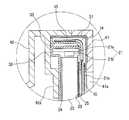
도 4는 도 3의 화살표 Ⅳ부분을 확대하여 도시한 상세단면도이다.
* 도면의 주요 부분에 대한 부호의 간단한 설명 *
10 : 액정패널20 : 백라이트모듈
30 : 하우징40 : 프레임
50 : 제어부100 : 액정패널조립체
200 : 액정표시장치1 is a view showing a conventional liquid crystal display device.
Figure 2 is an exploded perspective view showing a liquid crystal panel assembly according to an embodiment of the present invention.
3 is a cross-sectional view showing a liquid crystal display device according to an embodiment of the present invention.
4 is an enlarged detailed cross-sectional view of the arrow IV of FIG. 3.
Brief description of symbols for the main parts of the drawings
10: liquid crystal panel 20: backlight module
30
50
200: liquid crystal display
도 2 내지 도 4는 본 발명의 일 실시예에 따른 액정패널조립체 및 액정표시장치를 도시한다.2 to 4 illustrate a liquid crystal panel assembly and a liquid crystal display device according to an embodiment of the present invention.
도시된 바와 같이, 본 발명의 액정패널조립체(100)는 액정패널(10), 이 액정패널(10)에 광을 조사하는 백라이트모듈(20), 및 하우징(30)을 포함한다.As shown, the liquid
액정패널(10)은 미세간격으로 이격되어 설치된 한 쌍의 기판, 기판과 기판 사이의 이격공간에 밀봉적으로 배치된 액정 등을 포함하는 다양한 형태의 액정패널이 적용될 수 있을 것이다.The
백라이트모듈(20)은 빛을 발생시키는 적어도 하나의 LED광원부(21), LED광원(21)의 빛을 안내하는 도광판(22), 도광판(22)의 빛을 액정패널(15)측으로 확산시키는 확산판(23) 및 도광판(22)의 후면에 배치된 반사판(24)을 포함한다.The
LED광원부(21)는 회로기판(21a) 및 이 회로기판(21a)에 실장된 복수의 LED(21b)를 포함한다. 각 LED(21b)는 도광판(22)의 측면방향으로 광을 조사하고, 도광판(22)은 LED광원부(21)에서의 광을 확산판(23)으로 유도하며, 확산판(23)은 도광판(22)으로부터 전달된 빛을 액정패널(10)로 확산시킨다. 도광판(22)의 광방출면의 반대면에는 반사판(24)이 구비되고, 도광판(22)의 광방출면의 반대면으로 유도되는 광은 반사판(24)을 통해 반사되어 확산판(23)으로 안내된다.The LED
바람직하게는, 본 발명은 도 2 및 도 3에 도시된 바와 같이 한 쌍의 LED광원부(21)가 도광판(22)의 양단부(보다 바람직하게는 상하단부)에 개별적으로 배치됨으로써 도광판(22)의 전면에 걸쳐 균일하게 빛을 전달할 수도 있을 것이다.Preferably, in the present invention, as shown in FIGS. 2 and 3, the pair of LED
한편, 본 발명의 LED광원부(21)는 도 2 및 도 3에 도시된 형태에만 한정되지 않고, 액정패널(10)의 중앙부에 배치된 단일의 LED광원부(21)로 이루어지는 등 그갯수 및 배치구조가 다양하게 변경실시될 수 있을 것이다.On the other hand, the LED
또한, 본 발명은 확산판(23) 및 액정패널(10) 사이에 집광시트(25)가 개재되고, 이러한 집광시트(25)는 프리즘 시트, 고휘도 강화필름 등과 같이 확산판(23)에 의해 확산된 빛을 액정패널(10)의 화상영역으로 집광시키는 역할을 한다.In the present invention, the
한편, 본 발명의 집광시트(25)에 프리즘 시트를 적용할 경우, P파만 통과하고 S파는 통과하지 못해 광효율이 저하되는 현상을 발생하므로, DBEF(Dual Brightness Enhance Film) 등과 같은 고휘도 강화필름이 이용될 수 있다.On the other hand, when the prism sheet is applied to the
이러한 고휘도 강화필름은 프리즘 시트에서 발생하는 빛의 손실(loss)을 줄이는 역할을 할수 있도록 개선된 반사형 편광자(Reflectiv polarizer)로서, S파의 손실을 줄일 수 있도록 S파 성분의 방향성을 P파와 같은 방향으로 바꿔줌으로써 그 휘도를 강화시켜 주는 역할을 한다.This high brightness reinforcement film is a reflective polarizer that is improved to reduce the loss of light generated from the prism sheet, and the direction of the S wave component such as the P wave to reduce the S wave loss. By changing the direction to play a role to enhance the brightness.
하우징(30)은 그 일부가 백라이트모듈(20)의 LED광원부(21)에 접촉 또는 비접촉되게 인접하고, 액정패널(10) 및 백라이트모듈(20)을 감싸도록 설치된다.A part of the
액정패널(10)의 화면이 노출되게 장착되는 전면하우징(31) 및 이 전면하우징(31)의 후면에 장착되는 후면하우징(32)을 포함한다.And a
전면하우징(31)은 개구(31a)를 가지고, 이 개구(31a)를 통해 액정패널(10)의 화면이 노출된다.The
후면하우징(32)은 백라이트모듈(20)의 후면에 장착되고, 이 후면하우징(32)은 백라이트모듈(20)의 LED광원부(21)에 접촉 또는 비접촉되게 인접한다.The
후면하우징(32)은 알루미늄, 전기아연도금강재, 구리, 흑연, 열전도성 플라스틱 등과 같은 열전도성 재질로 이루어지고, 이러한 열전도성 재질의 후면하우징(32)을 통해 LED광원부(21)에서 발생하는 고열의 발산이 매우 용이하게 이루어질 수 있다.The
바람직하게는, 후면하우징(32)은 LED광원부(21)를 감싸는 형태로 배치됨에 따라 LED광원부(21)에서 발생된 고열의 발산을 보다 용이하게 할 수 있다.Preferably, as the
그리고, 전면하우징(31) 및 후면하우징(32)은 액자 형태의 연결브라켓(33)을 통해 상호 결합될 수 있으며, 이 연결브라켓(33)과 전면하우징(31) 사이에는 액정용 구동회로기판(15)이 배치되고, 이 액정용 구동회로기판(15)은 플렉시블기판(14)을 통해 액정패널(10)에 접속되며, 이 액정용 구동회로기판(15)은 액정패널(10)의 화소용량을 구동 및 제어한다.In addition, the
연결브라켓(33)은 후면하우징(32)과 유사하게 열전도성 재질로 이루어질 수도 있다.The
본 발명의 액정표시장치(200)는 액정패널조립체(100) 및 이 액정패널조립체(100)가 장착되는 프레임(40)을 포함한다.The
프레임(40)은 액정패널(10)의 유효표시영역이 외부로 노출되게 장착되는 전면프레임(41) 및 액정패널조립체(100)의 후면에 장착되는 후면프레임(42)을 포함한다.The
전면프레임(41)은 액정패널조립체(100)의 전면하우징(31)의 개구(31a)에 대응하는 개구(41a)를 가지고, 이 개구(41a)를 통해 액정패널(10)의 유효표시영역이 노출된다.The
후면프레임(42)은 액정패널조립체(100)의 LED광원부(21)에 접촉 또는 비접촉되게 인접하고, 알루미늄, 전기아연도금강재, 구리 등과 같은 열 및 전기 전도성 재질로 이루어진다.The
바람직하게는, 후면프레임(42)은 그 내측에 접촉부(42a)를 구비하고, 이 접촉부(42a)를 통해 액정패널조립체(100)의 후면하우징(32)과 접촉한다.Preferably, the
이와 같이, 후면프레임(42) 및 후면하우징(32)이 상호 접촉됨에 따라, LED광원부(21)에서 발생한 고열은 후면하우징(32) 및 후면프레임(42)을 통해 보다 효과적으로 외부로 방출될 수 있다.As such, as the
그리고, 후면프레임(42) 및 후면하우징(32) 사이에는 제어부(50)가 개재된다. 이 제어부(50)는 전원공급을 제어하는 전원공급장치(SMPS), 인버터, 액정표시장치의 각종 제어 및 구동신호를 제어하는 주제어기판(main conrtol board), 그외의 각종 전기소자 및 센서류 등으로 이루어져, 액정표시장치(200)의 전체 작동을 구동 및 제어할 수 있다.In addition, the
한편, 후면 프레임(42)은 알루미늄, 전기아연도금강재, 구리 등과 같은 열전동성 및 전기전도성을 가진 재질로 이루어져 제어부(50)의 후면에 배치됨에 따라, 제어부(50)의 작동에 의해 발생하는 전자파를 효과적으로 차폐할 수 있는 전자파 차폐 기능을 겸할 수 있다.On the other hand, the
이러한 본 발명은, LED광원부(21)에 접촉 또는 비접촉하게 인접한 후면하우징(32) 및/또는 후면프레임(42)이 열전도성 재질로 이루어짐에 따라 LED광원부(21)에서 발생하는 고열을 외부로 보다 효율적으로 방출시킬 수 있고, 이로 인해 LED광원부(21)의 발열온도를 낮출 수 있으므로 LED광원부(21)의 휘도를 향상시킴과 더불어 액정표시장치의 표시품질을 향상시킬 수 있다.The present invention, as the
또한, 본 발명은 LED광원부(21)의 발열을 효과적으로 수행함에 따라 LED광원부(21)의 전력 낭비를 최소화할 수 있으므로 에너지 효율을 극대화시킨 장점이 있다.In addition, the present invention has the advantage of maximizing energy efficiency because it can minimize the power waste of the LED
그리고, 본 발명은 상술한 바와 같이 LED광원부(21)의 열발산구조가 단순하여 액정표시장치의 크기를 보다 컴팩트하게 구현할 수 있는 장점이 있다.In addition, the present invention has the advantage that the heat dissipation structure of the LED
한편, 본 발명은 후면프레임(42)이 전기전도성 재질로 이루어짐에 따라 제어부(50)에서 발생하는 전자파를 차폐함으로써, 별도의 차폐구조가 필요없는 장점이 있다.On the other hand, according to the present invention, since the
상기와 같은 본 발명은, 보다 컴팩트한 크기를 구현할 수 있고, 표시품질(disply quality)를 대폭 향상시킨 효과가 있다.The present invention as described above, it is possible to implement a more compact size, has the effect of significantly improving the display quality (disply quality).
또한, 본 발명은 높은 에너지 효율을 구현할 수 있으며, 백라이트모듈의 LED광원에서 발생하는 높은 고열을 보다 효과적으로 방출시킬 수 있는 장점이 있다.In addition, the present invention can implement a high energy efficiency, there is an advantage that can effectively emit a high high heat generated from the LED light source of the backlight module.
이상에서 본 발명의 특정한 바람직한 실시예에 대하여 도시하고 또한 설명하였다. 그러나, 본 발명은 상술한 실시예에 한정되지 아니하며, 특허청구범위에서 청구하는 본 발명의 요지와 사상을 벗어남이 없이 당해 발명에 속하는 기술분야에서 통상의 지식을 가진자라면 누구든지 다양한 수정과 변형실시가 가능할 것이다.The foregoing is a description of certain preferred embodiments of the present invention. However, the present invention is not limited to the above-described embodiments, and any person having ordinary skill in the art without departing from the spirit and spirit of the present invention as claimed in the claims may make various modifications and variations. Implementation will be possible.
Claims (12)
Translated fromKorean액정패널과, 백라이트모듈과, 상기 액정패널 및 상기 백라이트모듈을 수용하는 하우징을 포함하며, 상기 전면프레임의 후방에 배치되는 액정패널조립체;
상기 액정패널조립체의 후방에 배치되며 상기 액정패널조립체의 동작을 제어하는 제어부로서, 전원공급을 제어하는 전원공급장치(SMPS), 인버터, 및 구동신호를 제어하는 주제어기판을 포함하여 이루어지는 제어부; 및
상기 제어부의 후방에 배치되어 상기 액정패널조립체 및 상기 제어부를 수용하며, 열 및 전기 전도성 재질로 이루어진 후면프레임;을 포함하며,
상기 백라이트 모듈은 하나 이상의 LED광원부를 포함하고, 상기 LED광원부는 회로기판 및 상기 회로기판에 실장된 하나 이상의 LED를 포함하며,
상기 하우징은, 상기 후면프레임과 부분적으로 접촉하도록 배치되고 열전도성 재질로 이루어진 후면하우징을 포함하며,
상기 LED에서 발생되는 열은 상기 회로기판과 상기 후면하우징을 통해 상기 후면프레임에 전달되는 것을 특징으로 하는 액정표시장치.A front frame having an opening for exposing a screen;
A liquid crystal panel assembly including a liquid crystal panel, a backlight module, a housing accommodating the liquid crystal panel and the backlight module, and disposed behind the front frame;
A control unit disposed behind the liquid crystal panel assembly and controlling an operation of the liquid crystal panel assembly, the control unit including a power supply device (SMPS) for controlling a power supply, an inverter, and a main controller substrate for controlling a driving signal; And
And a rear frame disposed at the rear of the control unit to accommodate the liquid crystal panel assembly and the control unit and made of a thermally and electrically conductive material.
The backlight module includes at least one LED light source, wherein the LED light source includes a circuit board and at least one LED mounted on the circuit board,
The housing includes a rear housing made of a thermally conductive material and disposed in partial contact with the rear frame.
The heat generated from the LED is transferred to the rear frame through the circuit board and the rear housing.
상기 후면프레임은 알루미늄, 전기아연도금강재 및 구리 중에서 선택된 재질로 이루어진 것을 특징으로 하는 액정표시장치.The method of claim 1,
And the rear frame is made of a material selected from aluminum, galvanized steel, and copper.
상기 하우징은, 상기 액정패널의 전방에 배치되는 전면하우징을 더 포함하는 것을 특징으로 하는 액정표시장치.The method of claim 1,
The housing further comprises a front housing disposed in front of the liquid crystal panel.
상기 후면하우징은 상기 LED광원부를 감싸도록 배치되는 것을 특징으로 하는 액정표시장치.The method of claim 3,
The rear housing is arranged to surround the LED light source.
상기 후면하우징은 알루미늄, 전기아연도금강재, 구리, 흑연 및 열전도성 플라스틱 중에서 선택된 재질로 이루어진 것을 특징으로 하는 액정표시장치.5. The method of claim 4,
And the rear housing is made of a material selected from aluminum, electrogalvanized steel, copper, graphite, and thermally conductive plastic.
상기 백라이트모듈은,
상기 LED광원부로부터 조사된 빛을 상기 액정패널로 안내하는 도광판;
상기 도광판의 전면에 배치되며 상기 도광판으로부터 상기 액정패널을 향해 빛을 확산시키는 확산판;
상기 확산판의 전면에 배치되며 상기 확산판에 의해 확산된 빛을 상기 액정패널로 집광시키는 집광시트; 및
상기 도광판의 후면에 배치되어 상기 도광판으로부터 후방으로 조사되는 빛을 상기 액정패널을 향해 반사시키는 반사판;을 포함하는 것을 특징으로 하는 액정표시장치.5. The method of claim 4,
The backlight module,
A light guide plate for guiding light emitted from the LED light source to the liquid crystal panel;
A diffusion plate disposed on the front surface of the light guide plate to diffuse light from the light guide plate toward the liquid crystal panel;
A light collecting sheet disposed on a front surface of the diffusion plate and condensing light diffused by the diffusion plate to the liquid crystal panel; And
And a reflector disposed on a rear surface of the light guide plate to reflect light irradiated backward from the light guide plate toward the liquid crystal panel.
상기 회로기판은 상기 후면하우징과 접촉하도록 배치되는 것을 특징으로 하는 액정표시장치.The method of claim 1,
And the circuit board is in contact with the rear housing.
상기 회로기판은 상기 도광판의 일측면에 배치되는 것을 특징으로 하는 액정표시장치.The method of claim 7, wherein
And the circuit board is disposed on one side of the light guide plate.
상기 회로기판은 상기 도광판과 수직하게 배치되는 것을 특징으로 하는 액정표시장치.10. The method of claim 9,
And the circuit board is disposed perpendicular to the light guide plate.
상기 액정표시장치는 텔레비젼인 것을 특징으로 하는 액정표시장치.The method according to any one of claims 1 to 5 and 7 to 10,
And the liquid crystal display device is a television.
Priority Applications (1)
| Application Number | Priority Date | Filing Date | Title |
|---|---|---|---|
| KR1020100066978AKR101325794B1 (en) | 2010-07-12 | 2010-07-12 | Lyquid crystal panel assembly and lyquid crystal display having the same |
Applications Claiming Priority (1)
| Application Number | Priority Date | Filing Date | Title |
|---|---|---|---|
| KR1020100066978AKR101325794B1 (en) | 2010-07-12 | 2010-07-12 | Lyquid crystal panel assembly and lyquid crystal display having the same |
Related Parent Applications (1)
| Application Number | Title | Priority Date | Filing Date |
|---|---|---|---|
| KR1020060023068ADivisionKR100978045B1 (en) | 2006-03-13 | 2006-03-13 | Liquid crystal panel assembly and liquid crystal display device comprising the same |
Publications (2)
| Publication Number | Publication Date |
|---|---|
| KR20100093506A KR20100093506A (en) | 2010-08-25 |
| KR101325794B1true KR101325794B1 (en) | 2013-11-11 |
Family
ID=42757887
Family Applications (1)
| Application Number | Title | Priority Date | Filing Date |
|---|---|---|---|
| KR1020100066978AActiveKR101325794B1 (en) | 2010-07-12 | 2010-07-12 | Lyquid crystal panel assembly and lyquid crystal display having the same |
Country Status (1)
| Country | Link |
|---|---|
| KR (1) | KR101325794B1 (en) |
Citations (4)
| Publication number | Priority date | Publication date | Assignee | Title |
|---|---|---|---|---|
| KR20030005660A (en)* | 2001-07-10 | 2003-01-23 | 삼성전자 주식회사 | Liquid crystal display device |
| KR20030091147A (en)* | 2002-05-24 | 2003-12-03 | 삼성전자주식회사 | Liquid crystal display device |
| JP2005283852A (en)* | 2004-03-29 | 2005-10-13 | Kyocera Corp | Liquid crystal display |
| JP2005338178A (en)* | 2004-05-24 | 2005-12-08 | Sony Corp | Liquid crystal display device |
- 2010
- 2010-07-12KRKR1020100066978Apatent/KR101325794B1/enactiveActive
Patent Citations (4)
| Publication number | Priority date | Publication date | Assignee | Title |
|---|---|---|---|---|
| KR20030005660A (en)* | 2001-07-10 | 2003-01-23 | 삼성전자 주식회사 | Liquid crystal display device |
| KR20030091147A (en)* | 2002-05-24 | 2003-12-03 | 삼성전자주식회사 | Liquid crystal display device |
| JP2005283852A (en)* | 2004-03-29 | 2005-10-13 | Kyocera Corp | Liquid crystal display |
| JP2005338178A (en)* | 2004-05-24 | 2005-12-08 | Sony Corp | Liquid crystal display device |
Also Published As
| Publication number | Publication date |
|---|---|
| KR20100093506A (en) | 2010-08-25 |
Similar Documents
| Publication | Publication Date | Title |
|---|---|---|
| KR100978045B1 (en) | Liquid crystal panel assembly and liquid crystal display device comprising the same | |
| KR101807442B1 (en) | Backlight module and liquid crystal display device using backlight module | |
| JP6157738B2 (en) | Backlight module and liquid crystal display module using the backlight module | |
| JP2006011242A (en) | Liquid crystal display | |
| KR20130024018A (en) | Light emitting unit and liquid display apparatus having the same | |
| WO2007129419A1 (en) | Liquid crystal display | |
| KR101667630B1 (en) | Liquid crystal display device having good efficience of heat rediation therefrom | |
| JP4632720B2 (en) | Light source device and liquid crystal display device | |
| US9229155B2 (en) | Side-edge backlight module | |
| JP4587720B2 (en) | Light source device and liquid crystal display device having the same | |
| KR101687783B1 (en) | Liquid crystal display device | |
| KR101729776B1 (en) | Backlgiht unit and liquid crystal display device the same | |
| KR101679077B1 (en) | Backlgiht unit and liquid crystal display device the same | |
| KR101305364B1 (en) | Bottom Cover and Liquid Crystal Display including the same | |
| KR101325794B1 (en) | Lyquid crystal panel assembly and lyquid crystal display having the same | |
| KR20090104521A (en) | Backlight unit | |
| KR101443387B1 (en) | Backlight unit and liquid crystal display device having the same | |
| JP4683875B2 (en) | Light source device and liquid crystal display device | |
| KR101252880B1 (en) | Liquid crystal display divice | |
| KR20120009996A (en) | Flat panel display and assembly method | |
| KR100794568B1 (en) | The flat type fluorescent lamp | |
| KR20080096199A (en) | LCD Display Module | |
| KR20080075301A (en) | Liquid crystal display | |
| KR20060083614A (en) | Back light assembly and display device having same |
Legal Events
| Date | Code | Title | Description |
|---|---|---|---|
| A107 | Divisional application of patent | ||
| PA0107 | Divisional application | St.27 status event code:A-0-1-A10-A18-div-PA0107 St.27 status event code:A-0-1-A10-A16-div-PA0107 | |
| PG1501 | Laying open of application | St.27 status event code:A-1-1-Q10-Q12-nap-PG1501 | |
| A201 | Request for examination | ||
| PA0201 | Request for examination | St.27 status event code:A-1-2-D10-D11-exm-PA0201 | |
| R18-X000 | Changes to party contact information recorded | St.27 status event code:A-3-3-R10-R18-oth-X000 | |
| E902 | Notification of reason for refusal | ||
| PE0902 | Notice of grounds for rejection | St.27 status event code:A-1-2-D10-D21-exm-PE0902 | |
| E13-X000 | Pre-grant limitation requested | St.27 status event code:A-2-3-E10-E13-lim-X000 | |
| P11-X000 | Amendment of application requested | St.27 status event code:A-2-2-P10-P11-nap-X000 | |
| P13-X000 | Application amended | St.27 status event code:A-2-2-P10-P13-nap-X000 | |
| E701 | Decision to grant or registration of patent right | ||
| PE0701 | Decision of registration | St.27 status event code:A-1-2-D10-D22-exm-PE0701 | |
| GRNT | Written decision to grant | ||
| PR0701 | Registration of establishment | St.27 status event code:A-2-4-F10-F11-exm-PR0701 | |
| PR1002 | Payment of registration fee | St.27 status event code:A-2-2-U10-U11-oth-PR1002 Fee payment year number:1 | |
| PG1601 | Publication of registration | St.27 status event code:A-4-4-Q10-Q13-nap-PG1601 | |
| FPAY | Annual fee payment | Payment date:20160929 Year of fee payment:4 | |
| PR1001 | Payment of annual fee | St.27 status event code:A-4-4-U10-U11-oth-PR1001 Fee payment year number:4 | |
| P22-X000 | Classification modified | St.27 status event code:A-4-4-P10-P22-nap-X000 | |
| FPAY | Annual fee payment | Payment date:20170927 Year of fee payment:5 | |
| PR1001 | Payment of annual fee | St.27 status event code:A-4-4-U10-U11-oth-PR1001 Fee payment year number:5 | |
| FPAY | Annual fee payment | Payment date:20180921 Year of fee payment:6 | |
| PR1001 | Payment of annual fee | St.27 status event code:A-4-4-U10-U11-oth-PR1001 Fee payment year number:6 | |
| PR1001 | Payment of annual fee | St.27 status event code:A-4-4-U10-U11-oth-PR1001 Fee payment year number:7 | |
| PR1001 | Payment of annual fee | St.27 status event code:A-4-4-U10-U11-oth-PR1001 Fee payment year number:8 | |
| PR1001 | Payment of annual fee | St.27 status event code:A-4-4-U10-U11-oth-PR1001 Fee payment year number:9 | |
| PR1001 | Payment of annual fee | St.27 status event code:A-4-4-U10-U11-oth-PR1001 Fee payment year number:10 | |
| PR1001 | Payment of annual fee | St.27 status event code:A-4-4-U10-U11-oth-PR1001 Fee payment year number:11 | |
| PR1001 | Payment of annual fee | St.27 status event code:A-4-4-U10-U11-oth-PR1001 Fee payment year number:12 | |
| PR1001 | Payment of annual fee | St.27 status event code:A-4-4-U10-U11-oth-PR1001 Fee payment year number:13 |