KR101324721B1 - A treatment apparatus using radio frequency energy - Google Patents
A treatment apparatus using radio frequency energyDownload PDFInfo
- Publication number
- KR101324721B1 KR101324721B1KR1020110070674AKR20110070674AKR101324721B1KR 101324721 B1KR101324721 B1KR 101324721B1KR 1020110070674 AKR1020110070674 AKR 1020110070674AKR 20110070674 AKR20110070674 AKR 20110070674AKR 101324721 B1KR101324721 B1KR 101324721B1
- Authority
- KR
- South Korea
- Prior art keywords
- high frequency
- handpiece
- electrode
- contact
- frequency energy
- Prior art date
- Legal status (The legal status is an assumption and is not a legal conclusion. Google has not performed a legal analysis and makes no representation as to the accuracy of the status listed.)
- Active
Links
Images


Classifications
- A—HUMAN NECESSITIES
- A61—MEDICAL OR VETERINARY SCIENCE; HYGIENE
- A61N—ELECTROTHERAPY; MAGNETOTHERAPY; RADIATION THERAPY; ULTRASOUND THERAPY
- A61N5/00—Radiation therapy
- A—HUMAN NECESSITIES
- A61—MEDICAL OR VETERINARY SCIENCE; HYGIENE
- A61H—PHYSICAL THERAPY APPARATUS, e.g. DEVICES FOR LOCATING OR STIMULATING REFLEX POINTS IN THE BODY; ARTIFICIAL RESPIRATION; MASSAGE; BATHING DEVICES FOR SPECIAL THERAPEUTIC OR HYGIENIC PURPOSES OR SPECIFIC PARTS OF THE BODY
- A61H39/00—Devices for locating or stimulating specific reflex points of the body for physical therapy, e.g. acupuncture
- A61H39/08—Devices for applying needles to such points, i.e. for acupuncture ; Acupuncture needles or accessories therefor
- A—HUMAN NECESSITIES
- A61—MEDICAL OR VETERINARY SCIENCE; HYGIENE
- A61N—ELECTROTHERAPY; MAGNETOTHERAPY; RADIATION THERAPY; ULTRASOUND THERAPY
- A61N1/00—Electrotherapy; Circuits therefor
- A61N1/02—Details
- A61N1/04—Electrodes
- A61N1/06—Electrodes for high-frequency therapy
- A—HUMAN NECESSITIES
- A61—MEDICAL OR VETERINARY SCIENCE; HYGIENE
- A61B—DIAGNOSIS; SURGERY; IDENTIFICATION
- A61B18/00—Surgical instruments, devices or methods for transferring non-mechanical forms of energy to or from the body
- A61B18/04—Surgical instruments, devices or methods for transferring non-mechanical forms of energy to or from the body by heating
- A—HUMAN NECESSITIES
- A61—MEDICAL OR VETERINARY SCIENCE; HYGIENE
- A61B—DIAGNOSIS; SURGERY; IDENTIFICATION
- A61B18/00—Surgical instruments, devices or methods for transferring non-mechanical forms of energy to or from the body
- A61B18/18—Surgical instruments, devices or methods for transferring non-mechanical forms of energy to or from the body by applying electromagnetic radiation, e.g. microwaves
- A—HUMAN NECESSITIES
- A61—MEDICAL OR VETERINARY SCIENCE; HYGIENE
- A61N—ELECTROTHERAPY; MAGNETOTHERAPY; RADIATION THERAPY; ULTRASOUND THERAPY
- A61N1/00—Electrotherapy; Circuits therefor
- A61N1/02—Details
- A61N1/04—Electrodes
- A61N1/05—Electrodes for implantation or insertion into the body, e.g. heart electrode
- A61N1/0502—Skin piercing electrodes
- A—HUMAN NECESSITIES
- A61—MEDICAL OR VETERINARY SCIENCE; HYGIENE
- A61H—PHYSICAL THERAPY APPARATUS, e.g. DEVICES FOR LOCATING OR STIMULATING REFLEX POINTS IN THE BODY; ARTIFICIAL RESPIRATION; MASSAGE; BATHING DEVICES FOR SPECIAL THERAPEUTIC OR HYGIENIC PURPOSES OR SPECIFIC PARTS OF THE BODY
- A61H2201/00—Characteristics of apparatus not provided for in the preceding codes
- A61H2201/01—Constructive details
- A61H2201/0119—Support for the device
- A61H2201/0153—Support for the device hand-held
- A—HUMAN NECESSITIES
- A61—MEDICAL OR VETERINARY SCIENCE; HYGIENE
- A61H—PHYSICAL THERAPY APPARATUS, e.g. DEVICES FOR LOCATING OR STIMULATING REFLEX POINTS IN THE BODY; ARTIFICIAL RESPIRATION; MASSAGE; BATHING DEVICES FOR SPECIAL THERAPEUTIC OR HYGIENIC PURPOSES OR SPECIFIC PARTS OF THE BODY
- A61H2201/00—Characteristics of apparatus not provided for in the preceding codes
- A61H2201/01—Constructive details
- A61H2201/0173—Means for preventing injuries
- A61H2201/0184—Means for preventing injuries by raising an alarm
- A—HUMAN NECESSITIES
- A61—MEDICAL OR VETERINARY SCIENCE; HYGIENE
- A61H—PHYSICAL THERAPY APPARATUS, e.g. DEVICES FOR LOCATING OR STIMULATING REFLEX POINTS IN THE BODY; ARTIFICIAL RESPIRATION; MASSAGE; BATHING DEVICES FOR SPECIAL THERAPEUTIC OR HYGIENIC PURPOSES OR SPECIFIC PARTS OF THE BODY
- A61H2201/00—Characteristics of apparatus not provided for in the preceding codes
- A61H2201/10—Characteristics of apparatus not provided for in the preceding codes with further special therapeutic means, e.g. electrotherapy, magneto therapy or radiation therapy, chromo therapy, infrared or ultraviolet therapy
- A—HUMAN NECESSITIES
- A61—MEDICAL OR VETERINARY SCIENCE; HYGIENE
- A61H—PHYSICAL THERAPY APPARATUS, e.g. DEVICES FOR LOCATING OR STIMULATING REFLEX POINTS IN THE BODY; ARTIFICIAL RESPIRATION; MASSAGE; BATHING DEVICES FOR SPECIAL THERAPEUTIC OR HYGIENIC PURPOSES OR SPECIFIC PARTS OF THE BODY
- A61H2201/00—Characteristics of apparatus not provided for in the preceding codes
- A61H2201/16—Physical interface with patient
- A61H2201/1683—Surface of interface
- A61H2201/1685—Surface of interface interchangeable
- A—HUMAN NECESSITIES
- A61—MEDICAL OR VETERINARY SCIENCE; HYGIENE
- A61H—PHYSICAL THERAPY APPARATUS, e.g. DEVICES FOR LOCATING OR STIMULATING REFLEX POINTS IN THE BODY; ARTIFICIAL RESPIRATION; MASSAGE; BATHING DEVICES FOR SPECIAL THERAPEUTIC OR HYGIENIC PURPOSES OR SPECIFIC PARTS OF THE BODY
- A61H2201/00—Characteristics of apparatus not provided for in the preceding codes
- A61H2201/50—Control means thereof
- A61H2201/5005—Control means thereof for controlling frequency distribution, modulation or interference of a driving signal
- A—HUMAN NECESSITIES
- A61—MEDICAL OR VETERINARY SCIENCE; HYGIENE
- A61H—PHYSICAL THERAPY APPARATUS, e.g. DEVICES FOR LOCATING OR STIMULATING REFLEX POINTS IN THE BODY; ARTIFICIAL RESPIRATION; MASSAGE; BATHING DEVICES FOR SPECIAL THERAPEUTIC OR HYGIENIC PURPOSES OR SPECIFIC PARTS OF THE BODY
- A61H2201/00—Characteristics of apparatus not provided for in the preceding codes
- A61H2201/50—Control means thereof
- A61H2201/5023—Interfaces to the user
- A61H2201/5025—Activation means
- A—HUMAN NECESSITIES
- A61—MEDICAL OR VETERINARY SCIENCE; HYGIENE
- A61H—PHYSICAL THERAPY APPARATUS, e.g. DEVICES FOR LOCATING OR STIMULATING REFLEX POINTS IN THE BODY; ARTIFICIAL RESPIRATION; MASSAGE; BATHING DEVICES FOR SPECIAL THERAPEUTIC OR HYGIENIC PURPOSES OR SPECIFIC PARTS OF THE BODY
- A61H2201/00—Characteristics of apparatus not provided for in the preceding codes
- A61H2201/50—Control means thereof
- A61H2201/5023—Interfaces to the user
- A61H2201/5035—Several programs selectable
- A—HUMAN NECESSITIES
- A61—MEDICAL OR VETERINARY SCIENCE; HYGIENE
- A61H—PHYSICAL THERAPY APPARATUS, e.g. DEVICES FOR LOCATING OR STIMULATING REFLEX POINTS IN THE BODY; ARTIFICIAL RESPIRATION; MASSAGE; BATHING DEVICES FOR SPECIAL THERAPEUTIC OR HYGIENIC PURPOSES OR SPECIFIC PARTS OF THE BODY
- A61H2201/00—Characteristics of apparatus not provided for in the preceding codes
- A61H2201/50—Control means thereof
- A61H2201/5058—Sensors or detectors
- A61H2201/5071—Pressure sensors
- A—HUMAN NECESSITIES
- A61—MEDICAL OR VETERINARY SCIENCE; HYGIENE
- A61H—PHYSICAL THERAPY APPARATUS, e.g. DEVICES FOR LOCATING OR STIMULATING REFLEX POINTS IN THE BODY; ARTIFICIAL RESPIRATION; MASSAGE; BATHING DEVICES FOR SPECIAL THERAPEUTIC OR HYGIENIC PURPOSES OR SPECIFIC PARTS OF THE BODY
- A61H2230/00—Measuring physical parameters of the user
- A61H2230/65—Impedance, e.g. skin conductivity; capacitance, e.g. galvanic skin response [GSR]
Landscapes
- Health & Medical Sciences (AREA)
- Life Sciences & Earth Sciences (AREA)
- Engineering & Computer Science (AREA)
- Animal Behavior & Ethology (AREA)
- Veterinary Medicine (AREA)
- Public Health (AREA)
- General Health & Medical Sciences (AREA)
- Biomedical Technology (AREA)
- Nuclear Medicine, Radiotherapy & Molecular Imaging (AREA)
- Radiology & Medical Imaging (AREA)
- Rehabilitation Therapy (AREA)
- Heart & Thoracic Surgery (AREA)
- Surgery (AREA)
- Epidemiology (AREA)
- Pain & Pain Management (AREA)
- Physical Education & Sports Medicine (AREA)
- Cardiology (AREA)
- Molecular Biology (AREA)
- Medical Informatics (AREA)
- Physics & Mathematics (AREA)
- Otolaryngology (AREA)
- Pathology (AREA)
- Plasma & Fusion (AREA)
- Electromagnetism (AREA)
- Surgical Instruments (AREA)
Abstract
Translated fromKoreanDescription
Translated fromKorean본 발명은 고주파를 이용한 치료 장치에 관한 것으로, 상세하게는 고주파 에너지를 이용하여 피부 조직을 치료할 수 있는 고주파를 이용한 치료장치에 관한 것이다.The present invention relates to a treatment apparatus using a high frequency, and more particularly, to a treatment apparatus using a high frequency capable of treating skin tissue using high frequency energy.
최근 들어, 다양한 에너지원을 이용하여 피부에 에너지를 제공함으로써 피부 조직 상태를 변형시키거나, 조직 특성을 개선하여 피부를 치료하는 기술이 널리 적용되고 있다. 레이저 빔, 플래시 램프, 초음파 등의 다양한 에너지원을 이용한 피부 치료장치가 개발되고 있으며, 최근에는 RF 고주파(radio frequency wave) 에너지를 이용한 피부 치료 장치에 대한 연구가 활발하게 이루어지고 있다.In recent years, technology for treating skin by modifying skin tissue state or improving tissue characteristics by providing energy to the skin using various energy sources has been widely applied. Skin treatment apparatuses using various energy sources such as laser beams, flash lamps, and ultrasounds have been developed. Recently, research on skin treatment apparatuses using RF radio frequency wave energy has been actively conducted.
피부 표면으로 고주파 에너지가 제공되면, 고주파의 전류 방향이 바뀔 때마다 피부 조직을 구성하는 분자들이 진동하면서 서로 마찰하게 되어, 회전 운동, 뒤틀림 또는 충돌 운동에 의해 심부열을 발생시킨다. 이러한 심부열은 피부 조직의 온도를 상승시켜 콜라겐층을 재조직하여 주름을 개선하고 피부 탄력을 강화시킬 수 있다. 또한, 피부 조직의 혈액 순환을 증진시켜 혈액 순환을 증진시킴으로써 피부 노화 방지를 비롯하여 피부의 전반적인 상태를 개선시키는 효과를 갖는다.When high frequency energy is provided to the skin surface, the molecules constituting the skin tissue vibrate and rub with each other whenever the direction of the high frequency current changes, causing deep heat by rotational motion, twisting or collisional motion. This deep heat can increase the temperature of the skin tissue to reorganize the collagen layer to improve wrinkles and enhance skin elasticity. In addition, it has the effect of improving the overall condition of the skin, including prevention of skin aging by promoting blood circulation by promoting blood circulation of the skin tissue.
대한민국 공개특허 2010-0101420 (2010. 9. 17 공개)는 고주파를 이용한 치료장치를 개시하고 있다.Republic of Korea Patent Publication 2010-0101420 (published Sep. 17, 2010) discloses a treatment device using a high frequency.
여기서, 고주파를 이용한 치료는 고주파 에너지가 제공되는 피부의 위치에 따라 상이한 효과가 나타난다. 따라서, 치료 목적에 따라 고주파를 제공하는 위치를 시술에 따라 달리하는 것이 최적의 치료 효과를 볼 수 있으나, 종래의 고주파를 이용한 치료장치는 하나의 장비를 이용하여 다양한 시술을 진행하는 것이 어려운 문제가 있었다.Here, the treatment using high frequency has different effects depending on the position of the skin where the high frequency energy is provided. Therefore, it is possible to see the optimal treatment effect by varying the position to provide a high frequency according to the treatment according to the treatment purpose, the conventional treatment apparatus using a high frequency is difficult to proceed a variety of procedures using a single equipment there was.
본 발명은 상기와 같은 문제점을 해결하기 위한 것으로, 시술 내용에 따라 피부의 다양한 위치에 고주파 에너지를 제공할 수 있는 고주파를 이용한 치료장치를 제공하기 위함이다.The present invention is to solve the above problems, and to provide a treatment apparatus using a high frequency that can provide high frequency energy to various locations of the skin according to the procedure.
상기한 본 발명의 목적은, 내부에 고주파 발생부를 구비하는 본체, 상기 본체의 체결부에 착탈 가능하게 형성되며, 상기 고주파 발생부에서 발생되는 고주파 에너지를 피부 표면으로 제공하는 제1 전극부를 구비하는 접촉식 핸드 피스, 상기 본체의 체결부에 착탈 가능하게 형성되며, 상기 고주파 발생부에서 발생되는 고주파 에너지를 피부 내측으로 제공하는 제2 전극부를 구비하는 침습식 핸드피스 그리고, 상기 고주파 발생부로부터 상기 제1 전극부 또는 상기 제2 전극부로 제공되는 고주파 에너지를 제어하는 제어부를 포함하는 고주파를 이용한 치료장치에 의해 달성될 수 있다.The object of the present invention described above is provided with a main body having a high frequency generating portion therein, a first electrode portion detachably formed to provide a high frequency energy generated by the high frequency generating portion to the skin surface. An invasive handpiece, which is detachably formed on a fastening part of the main body, and has a second electrode part for providing high frequency energy generated by the high frequency generating part to the inside of the skin. It may be achieved by a treatment apparatus using a high frequency including a control unit for controlling the high frequency energy provided to the first electrode portion or the second electrode portion.
여기서, 고주파를 이용한 치료장치는 상기 접촉식 핸드피스와 상기 침습식 핸드피스 중 상기 체결부에 연결되는 핸드피스의 종류를 감지하는 감지부를 더 포함할 수 있다.Here, the treatment apparatus using a high frequency may further include a sensing unit for detecting the type of the handpiece connected to the fastening unit of the contact handpiece and the invasive handpiece.
그리고, 상기 제어부는 설정된 동작 모드와 상기 감지부로부터 감지된 핸드피스의 종류를 비교하고, 상기 체결부에 상기 설정된 동작 모드와 대응되는 핸드피스가 연결되지 않은 것으로 판단되면 이상 신호를 생성할 수 있다.The controller may compare the set operation mode with the type of the handpiece detected by the sensing unit, and generate an abnormal signal when it is determined that the handpiece corresponding to the set operation mode is not connected to the fastening unit. .
나아가, 상기 제어부는 상기 체결부에 상기 설정된 동작모드와 대응되는 핸드피스가 연결되지 않은 것으로 판단되면, 상기 고주파 발생부로부터 상기 핸드피스로 고주파 에너지가 제공되지 않도록 제어하는 것도 가능하다.Further, when it is determined that the handpiece corresponding to the set operation mode is not connected to the fastening part, the controller may control the high frequency energy from being supplied from the high frequency generator to the handpiece.
또는, 상기 제어부는 상기 감지부로부터 감지된 핸드피스의 종류에 따라 서로 상이한 모드로 상기 고주파 발생부를 제어할 수도 있다.Alternatively, the controller may control the high frequency generator in different modes according to the type of the handpiece detected by the detector.
한편, 상기 접촉식 핸드피스는 상기 제1 전극부와 피부와의 접촉 상태를 감지하는 제1 센서를 구비하고, 상기 제어부는 상기 제1 센서에서 감지되는 정보에 기초하여 상기 제1 전극부와 피부의 접촉 상태가 불량한 것으로 판단되면 접촉 불량 신호를 생성할 수 있다.On the other hand, the contact handpiece has a first sensor for detecting a contact state between the first electrode and the skin, the control unit based on the information detected by the first sensor and the skin If it is determined that the contact state of the bad can generate a bad contact signal.
한편, 상기 침습식 핸드피스는 상기 제2 전극부가 피부 내측으로 삽입되는 동력을 제공하는 구동부를 더 포함하고, 상기 제어부는 설정된 동작 모드가 상기 침습식 핸드피스에 대응되는 동작 모드가 아닌 것으로 판단되면, 상기 구동부로부터 상기 제2 전극부로 동력이 제공되지 않도록 제어할 수 있다.On the other hand, the invasive handpiece further includes a driving unit for providing power to the second electrode portion is inserted into the skin, the control unit is determined that the set operation mode is not the operation mode corresponding to the invasive handpiece The controller may be configured to prevent power from being supplied from the driving unit to the second electrode unit.
또는, 상기 제2 전극부는 상기 침습식 핸드피스에 교체 가능하게 설치되며, 상기 침습식 핸드피스는 설치된 상기 제2 전극부의 종류를 감지하는 제2 센서를 더 포함할 수 있다.Alternatively, the second electrode part may be installed to be replaced with the invasive handpiece, and the invasive handpiece may further include a second sensor for sensing the type of the second electrode part installed.
여기서, 상기 제어부는 설정된 동작 모드와 상기 제2 센서에서 감지된 상기 제2 전극부의 종류를 비교하고, 상기 침습식 핸드피스에 설치된 상기 제2 전극부가 상기 설정된 동작 모드와 대응되지 않는 것으로 판단되면 이상 신호를 생성하도록 구성하는 것도 가능하다. 또는, 상기 제어부는 상기 제2 센서로부터 감지된 상기 제2 전극부의 종류에 따라 서로 상이한 모드로 상기 고주파 발생부를 제어하도록 구성하는 것도 가능하다.Here, the control unit compares the type of the second electrode unit detected by the set operation mode and the second sensor, and if it is determined that the second electrode unit installed in the invasive handpiece does not correspond to the set operation mode is abnormal It is also possible to configure to generate a signal. Alternatively, the controller may be configured to control the high frequency generator in different modes according to the type of the second electrode detected by the second sensor.
한편, 상기한 본 발명의 목적은, 본체에 구비되는 고주파 발생부, 상기 본체에 연결 설치되고 상기 고주파 발생부에서 발생되는 고주파 에너지를 피부 표면으로 제공하는 제1 전극부를 구비하는 접촉식 핸드피스, 상기 본체에 연결 설치되고, 상기 고주파 발생부에서 발생되는 고주파 에너지를 피부 내측으로 제공하는 제2 전극부를 구비하는 침습식 핸드피스 그리고, 상기 고주파 발생부에서 발생되는 고주파 에너지가 상기 제1 전극부 또는 상기 제2 전극부로 택일적으로 제공되도록 제어하는 제어부를 포함하는 고주파를 이용한 치료장치에 의해 달성되는 것도 가능하다.On the other hand, the object of the present invention, a contact handpiece having a high frequency generating portion provided in the main body, a first electrode portion connected to the main body and providing a high frequency energy generated by the high frequency generating portion to the skin surface, It is connected to the main body, the invasive handpiece having a second electrode portion for providing the high frequency energy generated by the high frequency generator into the skin, and the high frequency energy generated by the high frequency generator is the first electrode portion or It may also be achieved by a treatment apparatus using a high frequency including a control unit for controlling to be provided to the second electrode unit.
여기서, 고주파를 이용한 치료장치는 상기 접촉식 핸드피스 및 상기 침습식 핸드피스 중 사용자에 의해 사용되는 핸드피스의 종류를 감지하는 감지부를 더 포함하여 구성될 수 있다.Here, the treatment apparatus using a high frequency may further comprise a sensing unit for detecting the type of the handpiece used by the user of the contact handpiece and the invasive handpiece.
그리고, 상기 제어부는 설정된 동작 모드와 상기 감지부로부터 감지된 핸드피스의 종류를 비교하고, 상기 설정된 동작 모드와 대응되지 않은 핸드피스가 사용 중인 것으로 판단되면 이상 신호를 생성할 수 있다.The controller may compare the set operation mode with the type of the handpiece detected by the sensing unit, and generate an abnormal signal when it is determined that the handpiece that does not correspond to the set operation mode is in use.
나아가, 상기 제어부는 상기 설정된 동작 모드와 대응되지 않는 핸드피스가 사용 중인 것으로 판단되면, 상기 고주파 발생부로부터 상기 핸드피스로 고주파 에너지가 제공되지 않도록 제어하는 것도 가능하다.Further, when it is determined that a handpiece that does not correspond to the set operation mode is being used, the controller may control the high frequency energy from being supplied from the high frequency generator to the handpiece.
또는, 상기 제어부는 상기 감지부로부터 감지된 핸드피스의 종류에 따라 서로 상이한 모드로 상기 고주파 발생부를 제어할 수 있다.Alternatively, the controller may control the high frequency generator in different modes according to the type of the handpiece detected by the detector.
본 발명에 의할 경우 시술 내용에 따라 적합한 피부의 위치에 고주파 에너지를 제공할 수 있어 시술 효과를 개선할 수 있고, 하나의 장치를 이용하여 다양한 시술을 진행하는 것이 가능하므로 사용자가 치료 장치를 구입하는데 필요한 비용을 절감시킬 수 있다.According to the present invention can provide a high frequency energy to the location of the suitable skin according to the treatment content can improve the treatment effect, it is possible to proceed with a variety of procedures using a single device, so the user purchases a treatment device The cost required to do so can be reduced.
도 1은 본 발명의 제1 실시예에 따른 고주파를 이용한 치료장치를 도시한 사시도,
도 2는 도 1의 본체의 내부 구성을 개략적으로 도시한 블록도,
도 3은 도 1에서 본체에 접촉식 핸드피스가 체결된 상태를 개략적으로 도시한 블록도,
도 4는 도 3의 접촉식 핸드피스의 단부 형상을 도시한 사시도,
도 5는 도 4의 접촉식 핸드피스를 이용하여 피부를 치료하는 형상을 도시한 단면도,
도 6은 도 1의 본체에 침습식 핸드피스가 체결된 상태를 개략적으로 도시한 블록도,
도 7은 도 6의 침습식 핸드피스의 내부 구조를 도시한 단면도,
도 10은 본 발명의 제2 실시예에 따른 고주파를 이용한 치료장치를 도시한 사시도이고,
도 11은 도 10의 고주파를 이용한 치료장치의 구성을 개략적으로 도시한 개략도이다.1 is a perspective view showing a treatment apparatus using a high frequency according to the first embodiment of the present invention,
FIG. 2 is a block diagram schematically illustrating an internal configuration of the main body of FIG. 1;
3 is a block diagram schematically illustrating a state in which a contact handpiece is fastened to a main body in FIG. 1;
4 is a perspective view showing the end shape of the contact handpiece of FIG.
5 is a cross-sectional view showing a shape for treating the skin using the contact handpiece of FIG.
6 is a block diagram schematically illustrating a state in which an invasive handpiece is fastened to the main body of FIG. 1;
7 is a cross-sectional view showing the internal structure of the invasive handpiece of Figure 6,
10 is a perspective view showing a treatment apparatus using a high frequency according to the second embodiment of the present invention,
FIG. 11 is a schematic diagram schematically illustrating a configuration of a treatment apparatus using the high frequency of FIG. 10.
이하에서는 도면을 참조하여 본 발명의 실시예에 따른 고주파를 이용한 치료장치를 구체적으로 설명한다. 아래의 설명에서 각 구성요소의 위치관계는 원칙적으로 도면을 기준으로 설명한다. 그리고 도면은 설명의 편의를 위해 발명의 구조를 단순화하거나 필요할 경우 과장하여 표시될 수 있다. 따라서, 본 발명이 이에 한정되는 것은 아니며 이 이외에도 각종 장치를 부가하거나, 변경 또는 생략하여 실시할 수 있음은 물론이다.Hereinafter, a treatment apparatus using a high frequency according to an embodiment of the present invention with reference to the drawings in detail. In the following description, the positional relationship of each component is principally described based on the drawings. In addition, the drawings may be displayed by simplifying the structure of the invention or by exaggerating if necessary for the convenience of description. Therefore, the present invention is not limited thereto, and various other devices may be added, modified or omitted.
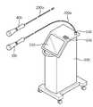
도 1은 본 발명의 제1 실시예에 따른 고주파를 이용한 치료장치를 도시한 사시도이다. 도 1에 도시된 바와 같이, 본 실시예에 따른 고주파 치료장치는 본체(100) 그리고 본체(100)에 착탈 가능하게 설치되는 접촉식 핸드피스(300) 및 침습식 핸드피스(400)를 포함한다.1 is a perspective view showing a treatment apparatus using a high frequency according to the first embodiment of the present invention. As shown in FIG. 1, the radio frequency treatment apparatus according to the present embodiment includes a
본체(100)는 외부로부터 전원을 공급받을 수 있는 전원 공급부(미도시)를 구비한다. 본체(100)의 외면에는 고주파를 이용한 치료장치의 구동 내용을 조작하기 위한 컨트롤 패널(control panel)(140) 및 이를 사용자에게 표시하는 디스플레이(display)(150)가 설치될 수 있다. 그리고 본체(100)의 내측에는 전원 공급부로부터 공급되는 전원을 이용하여 고주파 에너지를 발생시키는 고주파 발생부(110)가 구비된다. 그리고 본체(100)의 외면에는 접촉식 핸드피스(300) 및 침습식 핸드피스(400)가 체결될 수 있는 체결부가 형성된다.The
접촉식 핸드피스(300) 및 침습식 핸드피스(400)는 각각 몸체(310, 410) 및 전극부(320,420)를 포함하여 구성된다. 몸체(310, 410)는 핸드피스(300, 400)의 골격을 형성하며 사용자가 시술시 파지할 수 있는 구조로 구성된다. 몸체(310, 410)의 외면에는 사용자가 시술 중 핸드피스의 구동 내용을 간편하게 조작할 수 있는 조작부(330, 430)가 형성될 수 있다.The
접촉식 핸드피스(300) 및 침습식 핸드피스(400)의 단부에는 각각의 전극부(320,420)가 형성될 수 있다. 각각의 전극부(320,420)는 본체(100)의 고주파 발생부(110)로부터 제공되는 고주파 에너지를 피부에 제공할 수 있다. 접촉식 핸드피스(300)에 구비되는 제1 전극부(320)와 침습식 핸드피스(400)에 구비되는 제2 전극부(420)는 상이한 형상으로 구성되며, 각 전극부에 대한 구체적인 설명은 후술한다.The
이러한 접촉식 핸드피스(300) 및 침습식 핸드피스(400)는 케이블(200a, 200b)에 의해 본체(100)와 연결된다. 케이블(200a, 200b)의 내측에는 고주파 전달부(210a, 210b) 및 신호선(220a, 220b) 등을 포함하여 구성된다. 고주파 전달부는 본체(100)의 고주파 발생부(110)와 핸드피스(300, 400)에 구비되는 전극부(320, 420)를 전기적으로 연결하여 고주파 에너지를 피부로 제공할 수 있는 고주파 회로를 형성한다. 신호선은 본체와 핸드피스(300, 400) 사이에서 각종 제어신호 또는 감지 신호를 송수신한다. 예를 들어, 신호선은 사용자가 핸드피스의 조작부를 통해 조작하는 제어 신호 및 핸드피스에 구비된 센서에서 감지된 감지 신호를 본체에 구비되는 제어부로 전송할 수 있다. 또는 본체의 제어부가 핸드피스의 동작을 제어하기 위한 제어 신호를 신호선을 통해 핸드피스로 전송할 수도 있다.The
도 1에 도시된 바와 같이, 본 실시예에서는 접촉식 핸드피스(300) 및 침습식 핸드피스(400)의 일단에 각각의 케이블(200a, 200b)이 연장 형성된다. 그리고 각각의 케이블(200a, 200b)의 단부에는 본체(100)의 체결부(160)에 체결되기 위한 체결구가 각각 형성된다. 따라서, 사용자는 접촉식 핸드피스(300) 및 침습식 핸드피스(400) 중 사용하고자 하는 핸드피스의 체결구를 체결부(160)에 체결하여 시술을 진행할 수 있다. 또한 상이한 시술을 진행하기 위해 체결되어 있던 핸드피스를 분리하고, 나머지 핸드피스를 체결하여 교체 사용이 가능하다.As shown in FIG. 1, in this embodiment, each of the
본 실시예에서는 각각의 핸드피스가 별도의 케이블을 구비하고 체결부가 본체의 외면에 형성되는 구성을 일 예로 설명하였다. 그러나 이 이외에도 케이블이 본체와 연결 설치되고 케이블의 단부에 체결부가 형성되어, 각각의 핸드피스가 본체의 케이블에 연결되도록 구성하는 것도 가능하다.In this embodiment, each handpiece is provided with a separate cable and the fastening portion has been described as an example configuration formed on the outer surface of the main body. However, in addition to this, the cable is connected to the main body and a fastening portion is formed at the end of the cable, so that each handpiece can be configured to be connected to the cable of the main body.
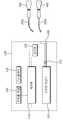
도 2는 도 1의 본체의 내부 구성을 개략적으로 도시한 블록도이다. 이하에서는 도 2를 참조하여 본 실시예에 따른 본체의 구성을 구체적으로 설명한다.2 is a block diagram schematically illustrating an internal configuration of the main body of FIG. 1. Hereinafter, the configuration of the main body according to the present embodiment will be described in detail with reference to FIG. 2.
앞서 설명한 바와 같이, 본체(100)는 사용자가 고주파를 이용한 치료장치의 동작 모드를 설정하는 컨트롤 패널(140), 치료장치의 동작 내용을 비롯한 각종 정보를 사용자에게 표시하는 디스플레이(150) 및 고주파 에너지를 발생시키는 고주파 발생부(110)를 비롯한 각종 구성요소가 설치된다. 그리고, 이러한 각종 구성요소를 제어하기 위한 제어부(120)를 구비한다.As described above, the
예를 들어, 사용자가 컨트롤 패널(140)을 통하여 동작 모드를 설정하면, 해당 모드에 대한 정보가 제어부(120)로 전송된다. 그리고, 제어부(120)는 설정된 동작 모드에 따라 해당 모드에 대응되는 동작을 수행하도록 고주파 발생부(110)를 비롯한 각종 구성요소를 제어한다. 또한, 제어부(120)는 고주파를 이용한 치료장치가 진행하는 운전 내용 및 각종 센서에서 감지된 정보 등을 디스플레이(150)를 통해 사용자에게 표시할 수 있다.For example, when a user sets an operation mode through the
나아가, 본체(100)는 체결부(160)에 연결되는 핸드피스의 종류를 감지하는 감지부(130)를 더 포함할 수 있다. 감지부(130)는 체결부(160)와 신호선 등에 의해 연결되어, 현재 본체(100)에 체결된 핸드피스가 접촉식 핸드피스(300)인지 침습식 핸드피스(400)인지를 식별한다. 그리고 감지부(130)에서 감지된 체결된 핸드피스에 대한 정보는 제어부(120)로 전송된다.Furthermore, the
일반적으로 피부 표면에 고주파 에너지를 제공하는 접촉식 핸드피스(300)와 피부 내측으로 고주파 에너지를 제공하는 침습식 핸드피스(400)는 서로 상이한 구성으로 이루어 파 발생 모듈(111, 112, 113)을 모두 구동하도록 제어하고, 침습식 핸드피스(400)가 설치된 것으로 감지된 경우 제어부(120)는 다수개의 고주파 발생 모듈 중 일부만 구동하도록 제어할 수 있다. 또는, 접촉식 핸드피스가 설치되는 것으로 감지된 경우에는 고주파 발생부(110)가 제1 주파수의 고주파 에너지를 발생시키도록 제어하고, 침습식 핸드피스(400)가 설치된 것으로 감지된 경우에는 제2 주파수의 고주파 에너지를 발생시키도록 제어할 수 있다. 또는 제어부(120)는 고주파 에너지가 전달되는 경로 상에 배치되는 릴레이 소자(170) 등의 회로 소자를 제어하여 고주파 에너지가 전달되는 각각의 경로를 선택적으로 차단하거나 경로를 전환시키는 등 체결된 핸드피스의 정보에 근거하여 다양하게 차별된 제어를 수행할 수 있다.In general, the
한편, 설정된 동작 모드와 대응하지 않는 핸드피스가 연결된 경우(예를 들어, 접촉식 핸드피스가 체결된 상태에서 침습용 핸드피스를 이용하는 모드를 설정한 경우) 원하는 시술을 진행하는 것이 어려울 뿐 아니라 본체 또는 핸드피스에 손상이 발생할 수 있다.On the other hand, when a handpiece that does not correspond to the set operation mode is connected (for example, when a mode using the invasive handpiece is set while the contact handpiece is fastened), it is difficult to proceed with a desired procedure, as well as the main body. Or damage to the handpiece may occur.
따라서, 본 실시예에 따른 제어부(120)는 설정된 동작 모드와 감지부(130)로부터 감지된 핸드피스의 종류를 비교하여, 대응되는 핸드피스가 체결부에 연결되지 않은 경우에는 이상 신호를 생성하여 사용자에게 알리도록 제어할 수 있다. 이때, 이상 신호는 디스플레이(150)를 통해 화면에 표시될 수도 있고, 경고음 형태로 사용자에게 알려질 수도 있다.Therefore, the
나아가, 제어부(120)는 설정된 동작 모드와 대응되는 핸드피스가 체결부(160)에 연결되지 않는 것으로 판단되면, 상기 고주파 발생부(110)로부터 핸드피스로 고주파 에너지가 제공되지 않도록 제어할 수 있다. 구체적으로, 고주파 발생부(110)의 동작을 강제적으로 멈추거나, 고주파 발생부(110)로부터 고주파 에너지가 전달되는 경로를 강제적으로 차단할 수 있다.Furthermore, when it is determined that the handpiece corresponding to the set operation mode is not connected to the
이와 같이 제어부(120)는 감지부에서 감지된 핸드피스의 정보에 근거하여 적합한 시술을 진행할 수 있도록 각종 구성요소를 제어할 뿐 아니라, 하나의 장치를 이용하여 서로 다른 두 종류의 핸드피스를 사용하는 경우 발생할 수 있는 오작동을 효과적으로 방지할 수 있다.In this way, the
이하에서는 도 3 및 도 5를 이용하여 본 실시예에 따른 접촉식 핸드피스가 설치된 치료 장치의 동작에 대해 구체적으로 설명한다.Hereinafter, the operation of the treatment device in which the contact handpiece according to the present embodiment is installed will be described in detail with reference to FIGS. 3 and 5.
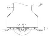
도 3은 도 1에서 본체에 접촉식 핸드피스가 체결된 상태를 개략적으로 도시한 블록도이고, 도 4는 도 3의 접촉식 핸드피스의 단부 형상을 도시한 사시도, 도 5는 도 4의 접촉식 핸드피스를 이용하여 피부를 치료하는 형상을 도시한 단면도이다.3 is a block diagram schematically showing a state in which the contact handpiece is fastened to the main body in FIG. 1, FIG. 4 is a perspective view illustrating an end shape of the contact handpiece of FIG. 3, and FIG. 5 is a contact of FIG. 4. It is sectional drawing which shows the shape which treats skin using a formula handpiece.
도 3에 도시된 바와 같이, 접촉식 핸드피스(300)는 사용자가 시술 중 접촉식 핸드피스(300)의 동작을 용이하게 조작할 수 있는 제1 조작부(330)가 형성된다. 그리고 접촉식 핸드피스(300)의 단부에는 피부 표면으로 고주파 에너지를 제공하는 제1 전극부(320)가 형성된다. As shown in FIG. 3, the
제1 전극부(320)는 다수개의 전극 모듈로 구성될 수 있다. 각각의 전극 모듈은 적어도 하나 이상의 양전극 및 음전극으로 구성된다. 도 3 내지 도 5에 도시된 바와 같이, 제1 전극부(320)는 제1 전극 모듈(321)과 상기 제1 전극 모듈(321)의 외측에 위치하는 제2 전극 모듈(322) 및 제3 전극 모듈(323)을 포함한다. 이때 각각의 전극 모듈은 피부와 소정 면적에서 접촉할 수 있도록 단부가 평면 또는 라운드 형상으로 이루어질 수 있다.The
제1 전극 모듈(321)은 도 4에 도시된 바와 같이, 플레이트에 형상의 지지판에 다수개의 양 전극(321a) 및 다수개의 음 전극(321b)이 배치된 구조로 구성된다. 그리고, 제2 전극 모듈(322)과 제3 전극 모듈(323)은 각각 양 전극(322a, 323a) 및 음 전극(322b, 323b)이 제1 전극 모듈(321)을 사이에 두고 대향되도록 양측에 배치된다. 이때, 제2 전극 모듈(322)의 양 전극(322a)과 음 전극(322b)이 배치된 방향은 제3 전극 모듈(323)의 양 전극(322a)과 음 전극(322b)이 배치된 방향과 직교하도록 형성될 수 있다.As shown in FIG. 4, the
한편, 본체(100)의 고주파 발생부(110)는 제1 고주파 발생모듈(111), 제2 고주파 발생모듈(112) 및 제3 고주파 발생모듈(113)을 포함할 수 있다. 따라서, 제1 내지 제3 고주파 발생모듈은 제1 내지 제3 전극모듈과 각각 독립된 경로를 형성하도록 전기적으로 연결된 상태에서 각각의 전극 모듈로 고주파 에너지를 제공한다.Meanwhile, the
이때, 각각의 고주파 발생모듈은 서로 다른 주파수의 고주파 에너지를 발생시킬 수 있도록 구성된다. 따라서, 제1 전극부(320)를 피부 표면에 접촉한 상태에서 고주파 발생부(110)로부터 고주파 에너지를 공급하면, 제1 고주파 발생모듈(111)에서 제공되는 고주파 에너지는 제1 전극모듈(321)의 양전극 및 음전극을 통해 독립된 회로를 구성하고, 제2 고주파 발생모듈(112)로부터 제공되는 고주파 에너지는 제2 전극 모듈(322)의 양전극 및 음전극과, 제3 고주파 발생모듈(113)로부터 제공되는 고주파 에너지는 제3 전극 모듈(323)의 양전극 및 음전극과 각각 독립된 회로를 구성한다(도 5 참조). 따라서, 치료가 이루어지는 피부의 위치에 다수개의 전극 모듈을 이용하여 중첩적으로 고주파 에너지를 제공할 수 있다.At this time, each high frequency generation module is configured to generate high frequency energy of different frequencies. Therefore, when the high frequency energy is supplied from the
이때, 각각의 전극 모듈을 통해 피부로 제공되는 고주파 에너지의 침투 깊이는 각 전극 모듈의 양전극과 음전극 사이의 간격에 의해 결정된다. 따라서, 제2 전극 모듈의 양전극 및 음전극의 간격과 제3 전극 모듈의 양전극 및 음전극의 간격을 다르게 형성하여 각 전극 모듈로부터 제공되는 고주파 에너지의 침투 깊이를 다양하게 형성할 수 있다(도 5 참조).At this time, the penetration depth of the high frequency energy provided to the skin through each electrode module is determined by the distance between the positive electrode and the negative electrode of each electrode module. Therefore, the gap between the positive electrode and the negative electrode of the second electrode module and the gap between the positive electrode and the negative electrode of the third electrode module may be formed differently to form various penetration depths of the high frequency energy provided from each electrode module (see FIG. 5). .
한편, 제어부(120)는, 앞서 설명한 바와 같이 컨트롤 패널(140)로부터 동작 모드가 설정되면, 설정된 동작 모드를 감지부(130)에서 감지된 핸드피스 정보와 비교하는 기능을 수행한다. 도 3의 경우, 침습식 핸드피스(400)를 이용하는 동작 모드가 설정된 것으로 판단되면, 제어부(120)는 디스플레이(150) 또는 별도의 경고음을 통해 이상 발생 사실을 사용자에게 전달할 수 있다. 그리고, 고주파 발생부의 동작을 제한하거나 또는 고주파 발생부(110)로부터 고주파 에너지가 전달되는 경로를 차단할 수 있다. 다만, 접촉식 핸드피스(300)를 이용하는 동작 모드가 설정된 것으로 판단되면 제어부(120)는 고주파 발생부를 비롯하여 각종 구성요소가 동작하도록 제어한다.Meanwhile, as described above, when the operation mode is set from the
여기서, 제어부(120)는 고주파 발생부(110)의 다수개의 고주파 발생모듈(111, 112, 113)을 각각 개별적으로 제어하도록 구성될 수 있다. 이 경우 각각의 고주파 발생모듈에서 발생하는 고주파 에너지의 출력을 제어하여, 피부의 침투 깊이에 따라 제공되는 고주파 에너지의 양을 제어할 수 있다. 따라서 제어부(120)의 제어에 의해 보다 다양한 내용의 시술이 가능하다.Here, the
나아가, 접촉식 핸드피스(300)는 제1 전극부(320)와 피부의 접촉 상태를 감지하는 제1 센서(340)를 포함할 수 있다. 이때, 제1 센서(340)는 접촉식 핸드피스의 단부에 설치되는 압력 센서 또는 임피던스 센서 등으로 구성될 수 있다.In addition, the
제1 센서(340)에서 감지된 접촉 상태 정보는 제어부(120)로 전송될 수 있다. 그리고 제어부(120)는 제1 센서(340)로부터 제1 전극부(320)의 피부 접촉 상태가 불량한 것으로 판단되면, 접촉 불량 신호를 생성하여 디스플레이(150) 또는 별도의 경고음을 통해 사용자에게 전달하도록 제어하는 것이 가능하다.The contact state information detected by the
이상에서 설명한 바와 같이 본실시예의 접촉식 핸드피스는 서로 다른 고주파 에너지를 제공하는 세 개의 전극 모듈 포함하도록 구성하였으나, 이는 일 예로서 본 발명이 전극 모듈의 개수에 한정되는 것은 아니며 하나의 고주파 에너지를 제공하는 접촉식 핸드피스를 구성하여 본 발명을 실시하는 것도 가능하다.As described above, the contact handpiece of the present embodiment is configured to include three electrode modules that provide different high frequency energy. However, the present invention is not limited to the number of electrode modules as an example. It is also possible to implement the invention by constructing a contact handpiece to provide.
이하에서는 도 6 및 도 7을 이용하여 본 실시예에 따른 침습식 핸드피스가 설치된 치료장치의 동작에 대해 구체적으로 설명한다.Hereinafter, the operation of the treatment device installed with the invasive handpiece according to the present embodiment will be described in detail with reference to FIGS. 6 and 7.
도 6은 도 1의 본체에 침습식 핸드피스가 체결된 상태를 개략적으로 도시한 블록도이고, 도 7은 도 6의 침습식 핸드피스의 내부 구조를 도시한 단면도이다.6 is a block diagram schematically illustrating a state in which the invasive handpiece is fastened to the main body of FIG. 1, and FIG. 7 is a cross-sectional view illustrating an internal structure of the invasive handpiece of FIG. 6.
도 6에 도시된 바와 같이, 침습식 핸드피스(400)는 사용자가 시술 중 핸드피스의 동작을 용이하게 조작할 수 있는 제2 조작부(430)를 구비한다. 그리고 침습식 핸드피스(400)의 단부에는 피부 내측으로 고주파 에너지를 제공하기 위한 제2 전극부(420)가 형성된다.As shown in FIG. 6, the
제2 전극부(420)는 플레이트(422)에 형성되는 단부가 뾰족한 다수개의 니들(needle)(421)을 포함하여 구성된다. 니들(needle)은 시술시 피부 표면을 관통하여 피부 내측으로 삽입된다. 본 실시예에서는 환자의 통증을 최소화시킴과 동시에 피부를 용이하게 관통할 수 있도록 니들 단부의 두께를 100㎛ 이하로 구성할 수 있다. 니들(421)은 단부를 통해 고주파 에너지를 피부로 제공할 수 있도록, 니들의 단부를 제외한 외면은 절연물질로 형성될 수 있다.The
이와 같은 제2 전극부(420)는, 도 7에 도시된 바와 같이, 구동부(450)에 의해 동력을 제공받아 이동 가능하게 설치된다. 따라서, 제2 전극부(420)를 피부에 접촉시킨 상태에서 제2 조작부(430)를 조작하여 구동부(450)를 구동하면, 다수개의 니들이 이동하면서 피부 내측으로 삽입된다.As shown in FIG. 7, the
이때, 다수개의 니들(421)이 일제히 피부에 삽입되는 경우 니들이 피부를 관통하는 것이 어렵고, 환자가 느끼는 통증이 클 수 있다. 따라서, 본 실시예에서는 다수개의 니들이 소정 각도(θ)만큼 경사진 상태로 피부 표면을 순차적으로 관통할 수 있도록 별도의 틸트(tilt)부를 구비한다.In this case, when the plurality of
본 실시예의 틸트부는 다수개의 니들이 배치된 플레이트 후면에 배치되는 탄성체(460a, 460b)로 구성된다. 이때 탄성체(460a, 460b)는 제2 전극부(420)의 플레이트(422) 후면 중 적어도 한 위치에서의 탄성 계수가 인접한 위치의 탄성 계수와 상이하도록 구성된다. 따라서, 제2 전극부(420)가 피부에 접촉한 상태에서 구동부(450)를 구동하게 되면 탄성체(460a, 460b)의 탄성 계수가 큰 위치에 배치되는 니들부터 피부 표면을 먼저 관통하고 나머지 니들이 순차적으로 관통할 수 있다.The tilt part of this embodiment is composed of
도 6에 도시된 바와 같이, 본 실시예의 틸트부는 다수개의 탄성체(460)를 이용하며, 각각의 탄성체(460)의 탄성계수가 상이하도록 구성할 수 있다. 다만 이는 일 예로서 위치에 따라 탄성 계수가 상이한 하나의 탄성체를 이용하여 틸트부를 구성하는 것도 가능하며, 이 이외에도 다양한 구조를 이용하여 다수개의 니들이 기울어진 상태로 피부 표면을 관통하도록 유도할 수 있다.As shown in FIG. 6, the tilt part of the present embodiment uses a plurality of elastic bodies 460 and may be configured to have different elastic modulus of each elastic body 460. However, as an example, the tilt part may be configured using one elastic body having a different elastic modulus according to the position. In addition to this, a plurality of needles may be used to penetrate the surface of the skin in a tilted state.
한편, 다수개의 니들이 형성된 플레이트로 이루어지는 제2 전극부(420)는 침습식 핸드피스(400)의 단부에 착탈 가능하게 설치될 수 있다. 따라서, 시술 위치 또는 시술의 목적에 따라 니들의 개수 또는 니들이 배치된 패턴이 각각 상이한 다수개의 모듈 중 적합한 것을 택일하여 제2 전극부(420)를 구성함으로써, 다양한 시술을 진행할 수 있다.On the other hand, the
이때, 침습식 핸드피스(400)는 제2 전극부(420)의 종류를 감지할 수 있는 제2 센서(440)를 구비할 수 있다. 제2 전극부(420)를 교체할 때마다 또는 시술을 진행할 때마다 제2 센서(440)에서 감지되는 제2 전극부(420)에 대한 정보가 제어부로 전송될 수 있다.In this case, the
한편 제어부(120)는, 앞서 설명한 바와 같이 컨트롤 패널(140)로부터 동작 모드가 설정되면, 감지부(130)에서 감지된 핸드피스 정보와 비교하는 기능을 수행한다. 도 6의 경우, 접촉식 핸드피스(300)를 이용하는 동작 모드가 설정된 것으로 판단되면, 제어부(120)는 디스플레이(150) 또는 별도의 경고음을 통해 이상 발생 사실을 사용자에게 전달할 수 있다. 그리고, 고주파 발생부(110)의 동작을 제한하거나 또는 고주파 발생부(110)로부터 고주파 에너지가 전달되는 경로를 차단할 수 있다. 또는 제어부(120)가 침습식 핸드피스(400)의 구동부(450)의 구동을 제한하거나 상기 구동부(450)로부터 제2 전극부로 동력이 전달되는 경로를 차단함으로써, 구동부(450)로부터 제2 전극부(420)로 동력이 제공되지 않도록 제어할 수 있다.Meanwhile, as described above, when the operation mode is set from the
다만, 침습식 핸드피스(400)를 이용하는 동작 모드가 설정된 것으로 판단되면 제어부(120)는 고주파 발생부(110)를 비롯하여 각종 구성요소가 동작하도록 제어한다.However, if it is determined that the operation mode using the
도 6에 도시된 바와 같이, 본 실시예에서는 고주파 발생부(110)의 다수개의 고주파 발생모듈 중 침습식 핸드피스(400)를 이용하는 경우 하나의 고주파 발생모듈만을 이용하도록 구성된다. 따라서, 제어부(120)는 하나의 고주파 발생모듈만을 구동하여 고주파 에너지를 발생시키고, 나머지 고주파 발생모듈을 제한하거나 이로부터 고주파 에너지가 전달되는 경로를 차단하도록 제어할 수 있다.As shown in FIG. 6, in the present embodiment, when using the
다만, 도 6에 도시된 고주파 발생부와 침습식 핸드피스가 연결되는 회로는 제2 전극부가 하나의 고주파 발생모듈과 전기적으로 연결되도록 구성하였으나, 이는 설명의 편의를 위한 일 예에 불과하며 이 이외에도 다양한 방식으로 설계할 수 있음을 밝혀둔다.However, the circuit in which the high frequency generating unit and the invasive handpiece shown in FIG. 6 are configured to electrically connect the second electrode unit to one high frequency generating module, but this is only an example for convenience of explanation and in addition to this. Note that it can be designed in a variety of ways.
나아가, 제어부는 제2 센서에서 감지된 제2 전극부(420)에 대한 정보에 근거하여, 서로 상이한 모드로 상기 고주파 발생부(110)를 제어할 수 있다. 예를 들어, 제어부는 넓은 간격으로 니들이 배치된 제2 전극부(420)가 체결된 경우에는 고주파 발생부(110)가 높은 출력의 에너지가 발생시키도록 제어할 수 있고, 제2 전극부(420)의 니들이 좁은 간격으로 배치된 제2 전극부(420)가 체결된 경우에는 고주파 발생부에서 낮은 출력의 에너지를 발생시키도록 제어할 수 있다.In addition, the controller may control the
또는, 제어부(120)는 설정된 동작 모드와 제2 전극부(420)에 대한 정보를 비교하여, 현재 설치된 제2 전극부(420)의 구조가 설정된 동작 모드와 대응되지 않는 것으로 판단되면 이상 신호를 생성하여 제2 전극부(420)를 교체하도록 사용자에게 알리도록 제어하는 것도 가능하다.Alternatively, the
이상에서 설명한 바와 같이 본 실시예에 따른 고주파를 이용한 치료장치는 접촉식 핸드피스 및 침습식 핸드피스를 교체하여 사용하도록 구성된다. 여기서 제어부는 체결되는 핸드피스의 종류에 근거하여 본체의 각종 구성요소를 제어함으로써 최적화된 시술을 가능하게 할 뿐 아니라, 상이한 핸드피스를 선택적으로 사용함으로써 발생할 수 있는 안전상의 문제를 방지할 수 있도록 제어할 수 있다.
As described above, the treatment apparatus using the high frequency according to the present embodiment is configured to replace the contact handpiece and the invasive handpiece. Here, the control unit not only enables an optimized procedure by controlling various components of the main body based on the type of the handpiece to be fastened, but also controls to prevent safety problems that may occur by selectively using different handpieces. can do.
이하에서는 도 8 및 도 9를 참조하여 전술한 제1 실시예에 따른 고주파를 이용한 치료장치의 제어방법에 대해 설명한다.Hereinafter, a method of controlling a treatment apparatus using high frequency according to the first embodiment will be described with reference to FIGS. 8 and 9.
도 8은 본 발명의 제1 실시예에 따른 고주파 치료장치의 제1 동작 모드에 따른 제어방법을 도시한 것이다. 도 8에 도시된 바와 같이, 사용자가 시술을 진행하기 위해 컨트롤 패널(140)을 통해 제1 동작모드로 운전할 것을 설정한다(S10). 이때, 제1 동작 모드는 설명의 편의를 위해 접촉식 핸드피스를 이용하여 진행하는 동작 모드인 것으로 가정한다.8 illustrates a control method according to a first operation mode of the radiofrequency therapy apparatus according to the first embodiment of the present invention. As shown in FIG. 8, the user sets to operate in the first operation mode through the
동작 모드가 설정되면, 체결부(160)에 체결된 핸드피스가 접촉식 핸드피스(300)인지 침습식 핸드피스(400)인를 감지하는 단계를 진행한다(S20). 이러한 단계는 감지부(130)에서 수행하며, 감지된 핸드피스의 종류에 대한 정보는 제어부(120)로 제공된다(S30).When the operation mode is set, the step of detecting whether the handpiece fastened to the
제어부(120)는 감지된 핸드피스가 침습식 핸드피스(400)인 것으로 판단되면 이상신호를 생성하여 디스플레이(150) 또는 별도의 경고음을 통해 사용자에게 통지한다(S31). 나아가, 체결된 침습식 핸드피스로 고주파 에너지가 제공되어 동작하는 것을 제한할 수 있다(S32). 이는, 고주파 발생부(110)가 동작하는 것을 제한하거나, 고주파 에너지가 전달되는 경로를 차단하거나 또는 침습식 핸드피스(400)의 구동부(450)의 동작을 제한하는 등 다양한 방식으로 이루어질 수 있다.If it is determined that the detected handpiece is the
반면, 감지된 핸드피스가 접촉식 핸드피스(300)인 것으로 판단되면, 제어부는 시술을 위한 운전을 정상적으로 진행할 수 있도록 각종 구성요소를 제어한다(S40).On the other hand, if it is determined that the detected handpiece is the
한편, 시술이 진행되는 동안, 접촉식 핸드피스(300)에 구비된 제1 센서(340)는 제1 전극부(320)와 피부의 접촉 상태를 감지하여 시술이 양호하게 진행되고 있는지를 파악한다(S50). 이때, 제1 센서(340)에서 제1 전극부(320)와 피부의 접촉상태가 양호하지 않은 것으로 파악되면, 제어부(120)는 접촉 불량신호를 생성하여 사용자에게 표시할 수 있다(S51). 이러한 제1 센서(340)의 동작은 시술이 진행되는 동안 주기적으로 또는 지속적으로 진행될 수 있다.On the other hand, during the procedure, the
이후, 설정된 제1 동작 모드의 운전 종료시점에 도달하였는지를 판단하여, 제어부는 각종 구성요소의 운전을 종료할 수 있다(S60).Subsequently, it is determined whether the operation end point of the set first operation mode has been reached, and the controller may end the operation of various components (S60).
한편, 도 9는 본 발명의 제1 실시예에 따른 고주파 치료장치의 제2 동작 모드에 따른 제어방법을 도시한 것이다. 이 경우, 사용자는 컨트롤 패널(140)을 통해 침습식 핸드피스를 이용하는 제2 동작모드로 운전할 것을 설정할 수 있다(S110).Meanwhile, FIG. 9 illustrates a control method according to a second operation mode of the radiofrequency treatment apparatus according to the first embodiment of the present invention. In this case, the user may set to operate in the second operation mode using the invasive handpiece through the control panel 140 (S110).
운전모드가 설정되면 앞서 설명한 바와 같이, 감지부(130)는 체결부(160)에 체결된 핸드피스의 종류를 감지하고(S120), 감지된 정보를 제어부(120)에 전송한다(S130). 그리고, 체결부(160)에 제2 동작모드에 대응되지 않는 접촉식 핸드피스(300)가 설치된 것으로 판단되면, 제어부(120)는 이상신호를 생성하여 사용자에게 표시할 수 있다(S131). 나아가 제어부(120)는 접촉식 핸드피스(300)로 고주파 에너지가 제공되는 것을 제한할 수 있다(S132).When the driving mode is set as described above, the
한편, 감지된 핸드피스가 침습식 핸드피스(400)인 것으로 판단되면, 제어부(120)는 시술을 위한 운전을 정상적으로 진행할 수 있도록 각종 구성요소를 제어한다(S160).On the other hand, if it is determined that the detected handpiece is the
다만, 전술한 바와 같이 침습식 핸드피스(400)는 제2 전극부(420)가 교체 가능하게 설치되어, 시술 내용에 따라 다양한 형태로 구성되는 다양한 제2 전극부 모듈 중 선택하여 사용하도록 구성될 수 있다. 그리고, 침습식 핸드피스(400)의 단부에는 제2 전극부(420)의 종류를 감지할 수 있는 제2 센서(440)가 구비된다.However, as described above, the
따라서, 침습식 핸드피스(400)는 시술 운전을 진행하기에 앞서 제2 센서(440)가 제2 전극부(420)의 종류를 감지하고(S140), 제어부(120)는 제2 센서(440)에서 감지된 제2 전극부의 종류가 제2 동작 모드와 대응되는지 여부를 판단할 수 있다(S150).Therefore, the
그리고, 제어부(120)는 현재 설치된 제2 전극부(420)이 제2 동작 모드에 대응되지 않는 것으로 판단되면, 교체 신호를 생성하여 사용자에게 이를 통지할 수 있다(ㄴ151). 반면, 제2 전극이 제2 동작 모드에 대응되는 것으로 판단된 상태에서 시술을 위한 정상 운전을 시작하도록 제어할 수 있다.If it is determined that the currently installed
이후, 설정된 제2 동작 모드의 운전 종료시점에 도달하였는지를 판단하여, 제어부는 각종 구성요소의 운전을 종료할 수 있다(S170).
Subsequently, it is determined whether the operation end point of the set second operation mode has been reached, and the controller may end the operation of various components (S170).
이하에서는 도 10 및 도 11을 참조하여 본 발명의 제2 실시예에 따른 고주파를 이용한 치료장치를 설명한다. 다만, 전술한 제1 실시예에서 설명한 구성요소와 대응되는 구성요소에 대해서는 동일한 명칭으로 명명하되, 유사한 기술 내용에 대해서는 설명의 중복을 피하기 위해 설명을 생략한다.Hereinafter, a treatment apparatus using high frequency according to a second embodiment of the present invention will be described with reference to FIGS. 10 and 11. However, constituent elements corresponding to the constituent elements described in the above-described first embodiment are named with the same names, and similar descriptions are omitted for avoiding duplication of description.
도 10은 본 발명의 제2 실시예에 따른 고주파를 이용한 치료장치를 도시한 사시도이고, 도 11은 도 10의 고주파를 이용한 치료장치의 구성을 개략적으로 도시한 개략도이다.10 is a perspective view showing a treatment apparatus using a high frequency according to the second embodiment of the present invention, Figure 11 is a schematic diagram showing the configuration of the treatment apparatus using a high frequency of FIG.
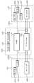
전술한 제1 실시예는 하나의 고주파를 이용한 치료장치에 접촉식 핸드피스와 침습식 핸드피스를 택일적으로 체결하여 사용할 수 있는 구성인 것에 비해, 본 실시예는 도 10에 도시된 바와 같이 하나의 고주파를 이용한 치료장치에 접촉식 핸드피스(1300) 및 침습식 핸드피스(1400)가 각각 연결 설치되는 구성이다.Compared to the first embodiment described above, the embodiment can be used by alternatively fastening a contact handpiece and an invasive handpiece to a treatment apparatus using a high frequency, as shown in FIG. 10. The
도 11에 도시된 바와 같이, 본체(1100)는 접촉식 핸드피스(1300)의 제1 전극부(1320) 및 침습식 핸드피스(1400)의 제2 전극부(1420)로 고주파 에너지를 제공할 수 있는 고주파 발생부(1110)를 구비한다. 그리고 사용자가 동작 모드를 설정할 수 있는 컨트롤 패널(1140) 및 운전 내용 및 치료 장치의 각종 정보를 표시할 수 있는 디스플레이(1150)가 구비된다. 그리고, 제어부(1120)는 고주파 발생부(1110), 컨트롤 패널(1140), 디스플레이(1150) 및 고주파 에너지가 전달되는 경로상에 설치되는 릴레이 소자(1170) 등의 각종 회로 소자와 연결되어, 본체에 구비되는 각종 구성요소를 제어한다.As shown in FIG. 11, the
접촉식 핸드피스(1300)는 제1 케이블(1200a)에 의해 본체(1100)와 연결 설치된다. 접촉식 핸드피스(1300)의 제1 전극부(1320)는 제1 케이블(1200a)에 구비되는 고주파 전달부(1210a)를 통해 본체(1100)의 고주파 발생부(1110)가 전기적으로 연결된다. 그리고, 제1 조작부(1330) 및 제1 센서(1340)는 제1 케이블(1200a)에 구비되는 신호선(1220a)에 의해 제어부와 연결될 수 있다.The
침습식 핸드피스(1400)는 제2 케이블(1200b)에 의해 본체(1100)와 연결 설치된다. 침습식 핸드피스(1400)의 제2 전극부(1420)는 제2 케이블(1200b)에 구비되는 고주파 전달부(1210b)를 통해 본체의 고주파 발생부(1110)와 연결된다. 그리고, 제2 조작부(1430), 구동부(1450) 및 제2 센서(1440)는 제2 케이블(1200b)에 구비되는 신호선(1220b)에 의해 제어부(1120)와 연결될 수 있다.The
본 실시예의 접촉식 핸드피스(1300)및 침습식 핸드피스(1400)의 구성 및 제어 방식은 전술한 실시예에서 상세히 설명하였으므로, 구체적인 설명은 생략한다.Since the configuration and control method of the
한편, 본 실시예에 따른 고주파를 이용한 치료장치는 시술자가 접촉식 핸드피스(1300) 또는 침습식 핸드피스(1400)를 택일적으로 선택하여 시술을 진행한다. 따라서, 고주파 발생부(1110)에서 발생되는 고주파 에너지가 접촉식 핸드피스(1300) 또는 침습식 핸드피스(1400) 중 택일적으로 제공되도록 제어부(1120)에 의해 제어될 수 있다.On the other hand, in the treatment device using the high frequency according to the present embodiment, the operator selects the
여기서, 본 실시예의 고주파를 이용한 치료장치는 사용자가 사용하는 핸드피스의 종류를 감지하는 감지부(미도시)를 더 포함한다. 이러한 감지부는 도면에 도시되지 않았으나 다양한 형태로 구성할 수 있다.Here, the treatment apparatus using the high frequency of the present embodiment further includes a detector (not shown) for detecting the type of handpiece used by the user. Although not shown in the drawings, the sensing unit may be configured in various forms.
일 예로서, 감지부는 접촉식 핸드피스(1300)와 침습식 핸드피스(1400)의 몸체 외면에 형성되는 센서 모듈로 구성될 수 있다. 따라서, 사용자가 핸드피스를 사용하는 경우 가해지는 압력, 온도 또는 전기적인 변화를 감지하여 사용자가 사용하고자 하는 핸드피스의 종류를 판별하는 것이 가능하다. 다른 예로서, 감지부는 접촉식 핸드피스 및 침습식 핸드피스가 거치되는 거치대에 설치되는 센서 모듈로 구성될 수도 있다. 따라서, 사용자가 접촉식 핸드피스와 침습식 핸드피스 중 하나를 선택하여 거치부로부터 탈거시키는 경우 발생하는 압력의 변화 등을 감지하여 이를 판별하도록 구성할 수 도 있다. 그리고, 전술한 두 가지 예 이외에도 다양한 방식으로 감지부를 구성하는 것이 가능하다.As an example, the sensing unit may be configured as a sensor module formed on the outer surface of the body of the
따라서, 제어부(1120)는 감지부에서 감지된 현재 사용중인 핸드피스의 정보를 따라, 상이한 모드로 고주파 발생부(1110)를 비롯한 각종 구성요소를 제어할 수 있다. Accordingly, the
예를 들어, 사용자가 접촉식 핸드피스(1300)를 사용하고자 하는 것으로 감지되면, 고주파 발생부(1110)로부터 침습식 핸드피스(1400)로 고주파 에너지를 제공하는 경로를 차단시킨다. 그리고 접촉식 핸드피스(1300)와 연결되는 신호선(1220a)을 활성화시키고, 침습식 핸드피스(1400)와 연결되는 신호선(1220b)은 비활성화시킬 수 있다.For example, if it is detected that the user intends to use the
다른 예로, 사용자가 침습식 핸드피스(1400)를 사용하고자 하는 것으로 감지되면, 침습식 핸드피스(1400)로 고주파 에너지를 제공하는데 사용되지 않는 고주파 발생 모듈(미도시)이 동작하지 않도록 제어할 수 있다. 그리고, 고주파 발생부(1110)로부터 접촉식 핸드피스(1300)로 고주파 에너지를 제공하는 경로를 차단시킨다. 나아가, 침습식 핸드피스(1400)와 연결되는 신호선(1220b)을 활성화시키고, 접촉식 핸드피스(1300)와 연결되는 신호선(1220a)은 비활성화시킬 수 있다.As another example, if it is detected that the user wants to use the
나아가, 제어부(1120)는 컨트롤 패널(1140)로부터 동작 모드가 설정되면, 감지부에서 감지된 핸드피스 정보와 비교하는 기능을 수행한다. 따라서, 설정된 동작모드와 대응하지 않는 핸드피스를 사용자가 사용하려는 것으로 판단되면, 제어부(1120)는 디스플레이(1150) 또는 별도의 경고음을 통해 이상 발생 사실을 사용자에게 전달할 수 있다. 그리고, 고주파 발생부(1110)의 동작을 제한하거나 또는 고주파 발생부로부터 고주파 에너지가 전달되는 경로를 차단할 수 있다. 반면, 설정된 동작모드와 대응되는 핸드피스를 사용자가 사용하는 것으로 판단되면, 제어부(1120)는 고주파 발생부(1110)를 비롯하여 각종 구성요소가 동작하도록 제어할 수 있다.Furthermore, when the operation mode is set from the
이처럼, 본 실시예와 같이 하나의 고주파를 이용한 치료장치에 서로 다른 두 개의 핸드피스를 연결하여 사용하는 경우에도, 제어부(1120)가 감지부에서 감지되는 핸드피스 사용정보에 근거하여 각종 구성요소를 제어함으로써, 최적화된 시술을 가능하게 할 뿐 아니라, 설정된 동작 모드와 대응되지 않는 핸드피스를 사용함으로써 발생할 수 있는 안전상의 문제를 방지할 수 있다.As such, even when two different handpieces are connected to the treatment apparatus using one high frequency wave as in the present embodiment, the
다만, 전술한 실시예들은 본 발명을 설명하기 위한 예시로서, 본 발명이 이에 한정되는 것은 아니다. 본 발명이 속하는 기술분야에서 통상의 지식을 가진 자라면 이로부터 다양하게 변형하여 본 발명을 실시하는 것이 가능할 것이므로, 본 발명의 기술적 보호범위는 첨부된 특허청구범위에 의해 정해져야 할 것이다.However, the above-described embodiments are examples for explaining the present invention, but the present invention is not limited thereto. Those skilled in the art to which the present invention pertains will be capable of carrying out the present invention by various modifications therefrom, and the technical protection scope of the present invention should be defined by the appended claims.
100 : 본체110 : 고주파 발생부
120 : 제어부130 : 감지부
160 : 체결부200a, 200b : 케이블
300 : 접촉식 핸드피스320 : 제1 전극부
400 : 침습식 핸드피스 420 : 제2 전극부100: main body 110: high frequency generation unit
120: control unit 130: detection unit
160:
300: contact handpiece 320: first electrode portion
400: invasive handpiece 420: second electrode portion
Claims (22)
Translated fromKorean상기 본체에 연결 설치되고, 상기 고주파 발생부에서 발생되는 고주파 에너지를 피부 표면으로 제공하는 제1 전극부를 구비하는 접촉식 핸드피스;
상기 본체에 연결 설치되고, 상기 고주파 발생부에서 발생되는 고주파 에너지를 피부 내측으로 제공하는 제2 전극부를 구비하는 침습식 핸드피스;
상기 고주파 발생부에서 발생되는 고주파 에너지가 상기 제1 전극부 또는 상기 제2 전극부로 택일적으로 제공되도록 제어하는 제어부 그리고,
상기 접촉식 핸드피스 및 상기 침습식 핸드피스 중 사용자에 의해 사용되는 핸드피스의 종류를 감지하는 감지부를 더 포함하며,
상기 제어부는 설정된 동작 모드와 상기 감지부로부터 감지된 핸드피스의 종류를 비교하고, 상기 설정된 동작 모드와 대응되지 않은 핸드피스가 사용 중인 것으로 판단되면 이상 신호를 생성하는 것을 특징으로 하는 고주파를 이용한 치료장치.A high frequency generator provided in the main body;
A contact handpiece connected to the main body and having a first electrode part configured to provide high frequency energy generated from the high frequency generator part to a skin surface;
An invasive handpiece connected to the main body and having a second electrode part configured to provide high frequency energy generated by the high frequency generator to the inside of the skin;
A controller for controlling the high frequency energy generated by the high frequency generator to be alternatively provided to the first electrode part or the second electrode part;
Further comprising a sensing unit for detecting the type of handpiece used by the user of the contact handpiece and the invasive handpiece,
The control unit compares the type of the handpiece detected by the sensing unit with the set operation mode, and generates an abnormal signal when it is determined that the handpiece that does not correspond to the set operation mode is in use. Device.
상기 접촉식 핸드피스는 상기 제1 전극부와 피부와의 접촉 상태를 감지하는 제1 센서를 구비하고, 상기 제어부는 상기 제1 센서에서 감지되는 정보에 기초하여 상기 제1 전극부와 피부의 접촉 상태가 불량한 것으로 판단되면 접촉 불량 신호를 생성하는 것을 특징으로 하는 고주파를 이용한 치료장치.15. The method of claim 14,
The contact handpiece may include a first sensor configured to detect a contact state between the first electrode part and the skin, and the controller may contact the skin with the first electrode part based on information detected by the first sensor. The treatment device using a high frequency, characterized in that for generating a bad contact signal if it is determined that the condition is bad.
상기 접촉식 핸드피스의 상기 제1 전극부는 복수개의 전극 모듈을 구비하고, 상기 고주파 발생부는 상기 복수개의 전극 모듈과 각각 대응되는 복수개의 고주파 발생모듈을 구비하고, 상기 제어부는 상기 복수개의 전극 모듈을 독립적으로 제어하여 상기 복수개의 전극 모듈을 통해 서로 다른 주파수의 고주파 에너지가 피부 표면으로 제공되는 것을 특징으로 하는 고주파를 이용한 치료장치.15. The method of claim 14,
The first electrode part of the contact handpiece includes a plurality of electrode modules, the high frequency generating part includes a plurality of high frequency generating modules respectively corresponding to the plurality of electrode modules, and the controller controls the plurality of electrode modules. Independently controlled treatment device using a high frequency, characterized in that the high-frequency energy of different frequencies are provided to the skin surface through the plurality of electrode modules.
상기 제어부는 상기 설정된 동작 모드와 대응되지 않는 핸드피스가 사용 중인 것으로 판단되면, 상기 고주파 발생부로부터 상기 핸드피스로 고주파 에너지가 제공되지 않도록 제어하는 것을 특징으로 하는 고주파를 이용한 치료장치.15. The method of claim 14,
The control unit, if it is determined that a handpiece that does not correspond to the set operation mode is in use, the high frequency energy from the high frequency generating unit to the handpiece treatment device, characterized in that for controlling the high-frequency energy.
상기 제어부는 상기 감지부로부터 감지된 핸드피스의 종류에 따라 서로 상이한 모드로 상기 고주파 발생부를 제어하는 것을 특징으로 하는 고주파를 이용한 치료장치.15. The method of claim 14,
The control unit is a treatment apparatus using a high frequency, characterized in that for controlling the high frequency generator in a different mode according to the type of the handpiece detected by the sensing unit.
상기 고주파 발생장치로부터 상기 제1 전극부 및 상기 제2 전극부로 고주파 에너지를 제공하는 경로 상에 적어도 하나의 릴레이 소자가 구비되고, 상기 제어부는 상기 적어도 하나의 릴레이 소자를 제어하여 고주파 에너지가 상기 제1 전극부 또는 상기 제2 전극부로 택일적으로 제공되도록 제어하는 것을 특징으로 하는 고주파를 이용한 치료장치.15. The method of claim 14,
At least one relay element is provided on a path for providing high frequency energy from the high frequency generator to the first electrode portion and the second electrode portion, and the controller controls the at least one relay element to generate the high frequency energy. Treatment apparatus using a high frequency, characterized in that the control to be provided to the first electrode unit or the second electrode unit.
접촉식 핸드피스 및 침습식 핸드피스 중 본체에 체결된 핸드피스의 종류를 감지하는 단계; 그리고,
고주파 발생부로부터 고주파를 발생하여 상기 체결된 핸드피스 방향으로 공급하는 단계를 포함하고,
상기 체결된 핸드피스가 상기 설정된 운전모드와 대응되는지 여부를 판단하는 단계를 더 포함하고, 상기 체결된 핸드피스가 상기 설정된 운전모드와 대응되지 않는 것으로 판단되면 이상 신호를 생성하는 것을 특징으로 하는 고주파를 이용한 치료장치의 제어방법.Setting a driving mode;
Sensing the type of handpiece fastened to the body of the contact handpiece and the invasive handpiece; And,
Generating a high frequency from a high frequency generating unit and supplying the high frequency toward the fastened handpiece;
And determining whether the fastened handpiece corresponds to the set driving mode, and generating an abnormal signal when it is determined that the fastened handpiece does not correspond to the set driving mode. Control method of treatment device using.
상기 체결된 핸드피스가 상기 설정된 운전모드와 대응되지 않는 것으로 판단되면 상기 고주파 발생부로부터 상기 체결된 핸드피스로 고주파 에너지가 제공되는 경로를 차단하는 것을 특징으로 하는 고주파를 이용한 치료장치의 제어방법.21. The method of claim 20,
And if it is determined that the fastened handpiece does not correspond to the set operation mode, blocking the path through which high frequency energy is supplied from the high frequency generator to the fastened handpiece.
Priority Applications (4)
| Application Number | Priority Date | Filing Date | Title |
|---|---|---|---|
| KR1020110070674AKR101324721B1 (en) | 2011-07-15 | 2011-07-15 | A treatment apparatus using radio frequency energy |
| US14/233,046US20140155963A1 (en) | 2011-07-15 | 2012-07-13 | Treatment device high frequency |
| PCT/KR2012/005552WO2013012204A2 (en) | 2011-07-15 | 2012-07-13 | Treatment device using high frequency |
| US15/957,720US10894171B2 (en) | 2011-07-15 | 2018-04-19 | Treatment device using high frequency |
Applications Claiming Priority (1)
| Application Number | Priority Date | Filing Date | Title |
|---|---|---|---|
| KR1020110070674AKR101324721B1 (en) | 2011-07-15 | 2011-07-15 | A treatment apparatus using radio frequency energy |
Related Child Applications (1)
| Application Number | Title | Priority Date | Filing Date |
|---|---|---|---|
| KR1020130033765ADivisionKR101743706B1 (en) | 2013-03-28 | 2013-03-28 | A treatment apparatus using radio frequency energy |
Publications (2)
| Publication Number | Publication Date |
|---|---|
| KR20130009511A KR20130009511A (en) | 2013-01-23 |
| KR101324721B1true KR101324721B1 (en) | 2013-11-05 |
Family
ID=47558579
Family Applications (1)
| Application Number | Title | Priority Date | Filing Date |
|---|---|---|---|
| KR1020110070674AActiveKR101324721B1 (en) | 2011-07-15 | 2011-07-15 | A treatment apparatus using radio frequency energy |
Country Status (3)
| Country | Link |
|---|---|
| US (2) | US20140155963A1 (en) |
| KR (1) | KR101324721B1 (en) |
| WO (1) | WO2013012204A2 (en) |
Families Citing this family (19)
| Publication number | Priority date | Publication date | Assignee | Title |
|---|---|---|---|---|
| KR20170068697A (en)* | 2015-12-09 | 2017-06-20 | 주식회사 하이로닉 | System for cosmetic skin rejuvenation method with the same |
| KR102550410B1 (en)* | 2015-12-22 | 2023-07-04 | 주식회사 하이로닉 | System for cosmetic skin rejuvenation with heterogeneous energy and method with the same |
| US9629991B1 (en) | 2016-06-08 | 2017-04-25 | Eclipse Aesthetics, LLC | Disposable radio frequency needle cartridges having absorbing containment barriers |
| US10220195B2 (en) | 2016-06-08 | 2019-03-05 | Eclipse Medcorp, Llc | Radio frequency needling device for use with disposable needle cartridges |
| KR101814109B1 (en)* | 2016-07-04 | 2018-01-02 | 주식회사 파나시 | Multifunction apparatus for skin treatment |
| KR20180081385A (en)* | 2017-01-06 | 2018-07-16 | 주식회사 루트로닉 | An treatment apparatus and a method for controlling that |
| US10850095B2 (en) | 2017-08-08 | 2020-12-01 | Pulse Biosciences, Inc. | Treatment of tissue by the application of energy |
| US11590345B2 (en) | 2017-08-08 | 2023-02-28 | Pulse Biosciences, Inc. | Treatment of tissue by the application of energy |
| KR102066046B1 (en)* | 2017-08-25 | 2020-01-14 | 주식회사 루트로닉 | An skin treatment apparatus using rf energy and a method for skin treatment using that |
| US10857347B2 (en) | 2017-09-19 | 2020-12-08 | Pulse Biosciences, Inc. | Treatment instrument and high-voltage connectors for robotic surgical system |
| KR102214341B1 (en)* | 2018-12-20 | 2021-02-10 | 주식회사 루트로닉 | Handpiece, RF treatment device and control method of RF treatment device |
| US11571569B2 (en) | 2019-02-15 | 2023-02-07 | Pulse Biosciences, Inc. | High-voltage catheters for sub-microsecond pulsing |
| KR102049483B1 (en)* | 2019-08-07 | 2019-11-27 | 주식회사 울트라브이 | Universal Electro-surgical device |
| JP7512052B2 (en)* | 2020-02-28 | 2024-07-08 | ヤーマン株式会社 | High frequency beauty device |
| KR102507309B1 (en)* | 2020-06-04 | 2023-03-08 | 주식회사 제이엘유 | High-frequency thermal therapy machine |
| KR102507312B1 (en)* | 2020-06-04 | 2023-03-08 | 주식회사 제이엘유 | High-frequency thermal therapy machine |
| KR102541214B1 (en)* | 2021-01-19 | 2023-06-13 | 주식회사 인메디 | Complex beautifying device based on ultrasonics wave |
| KR102616296B1 (en)* | 2021-11-24 | 2023-12-22 | 주식회사 청우메디칼 | Surgical navigation tool with needle electrode depth control structure and high-frequency energy control method using the same |
| KR102548999B1 (en)* | 2023-02-23 | 2023-06-28 | (주) 위드닉스 | Skincare Device Having Auto Sensing Function |
Citations (2)
| Publication number | Priority date | Publication date | Assignee | Title |
|---|---|---|---|---|
| KR200397295Y1 (en) | 2005-07-14 | 2005-09-29 | 주식회사 썸텍 | Electrical Stimulator having electrode perception function and temperature control function |
| KR20110002210A (en)* | 2009-07-01 | 2011-01-07 | 양원동 | Functional stagnation |
Family Cites Families (11)
| Publication number | Priority date | Publication date | Assignee | Title |
|---|---|---|---|---|
| US5383874A (en)* | 1991-11-08 | 1995-01-24 | Ep Technologies, Inc. | Systems for identifying catheters and monitoring their use |
| US6123702A (en)* | 1998-09-10 | 2000-09-26 | Scimed Life Systems, Inc. | Systems and methods for controlling power in an electrosurgical probe |
| JP4391706B2 (en)* | 2000-02-29 | 2009-12-24 | オリンパス株式会社 | Surgical system |
| JP2001258901A (en)* | 2000-03-15 | 2001-09-25 | Olympus Optical Co Ltd | Ultrasonic surgical instrument and medical system |
| JP4040914B2 (en)* | 2002-06-14 | 2008-01-30 | オリンパス株式会社 | Ultrasonic surgical device |
| GB0221707D0 (en)* | 2002-09-18 | 2002-10-30 | Gyrus Medical Ltd | Electrical system |
| KR200360150Y1 (en)* | 2004-06-02 | 2004-08-26 | 강동환 | Skin therapy equipment |
| US20070142885A1 (en)* | 2005-11-29 | 2007-06-21 | Reliant Technologies, Inc. | Method and Apparatus for Micro-Needle Array Electrode Treatment of Tissue |
| CN101765414B (en)* | 2007-04-20 | 2013-09-25 | 多汉尼眼科研究所 | Independent surgical center |
| US20090036958A1 (en)* | 2007-08-01 | 2009-02-05 | Primaeva Medical, Inc. | Methods and devices for treating tissue |
| US20090112205A1 (en)* | 2007-10-31 | 2009-04-30 | Primaeva Medical, Inc. | Cartridge electrode device |
- 2011
- 2011-07-15KRKR1020110070674Apatent/KR101324721B1/enactiveActive
- 2012
- 2012-07-13USUS14/233,046patent/US20140155963A1/ennot_activeAbandoned
- 2012-07-13WOPCT/KR2012/005552patent/WO2013012204A2/enactiveApplication Filing
- 2018
- 2018-04-19USUS15/957,720patent/US10894171B2/enactiveActive
Patent Citations (2)
| Publication number | Priority date | Publication date | Assignee | Title |
|---|---|---|---|---|
| KR200397295Y1 (en) | 2005-07-14 | 2005-09-29 | 주식회사 썸텍 | Electrical Stimulator having electrode perception function and temperature control function |
| KR20110002210A (en)* | 2009-07-01 | 2011-01-07 | 양원동 | Functional stagnation |
Also Published As
| Publication number | Publication date |
|---|---|
| US10894171B2 (en) | 2021-01-19 |
| KR20130009511A (en) | 2013-01-23 |
| WO2013012204A3 (en) | 2013-04-11 |
| US20180236256A1 (en) | 2018-08-23 |
| US20140155963A1 (en) | 2014-06-05 |
| WO2013012204A2 (en) | 2013-01-24 |
Similar Documents
| Publication | Publication Date | Title |
|---|---|---|
| KR101324721B1 (en) | A treatment apparatus using radio frequency energy | |
| KR20130044268A (en) | A treatment apparatus using radio frequency energy | |
| KR101314574B1 (en) | A treatment apparutus using radio frequency energy | |
| KR101300123B1 (en) | A treatment apparatus using radio frequency energy and a method for controling it | |
| KR102149061B1 (en) | Apparatus for cosmetic and medical treatment | |
| KR101716345B1 (en) | Appratus for skin care using high-frequency | |
| KR101277450B1 (en) | A treatment apparutus using radio frequency energy | |
| EP2046208B1 (en) | Apparatus for non-invasive treatment of skin tissue | |
| JP4371396B2 (en) | Multi-purpose template and needle for delivery and monitoring of multiple minimal expansion therapies | |
| JP3905482B2 (en) | Surgery system | |
| JP7708974B2 (en) | Skin treatment device capable of automatically outputting high-frequency energy and its control method | |
| US20090171253A1 (en) | System and method for dermatological treatment using ultrasound | |
| KR101811351B1 (en) | High intensity focused ultrasound operating apparatus | |
| KR102066046B1 (en) | An skin treatment apparatus using rf energy and a method for skin treatment using that | |
| KR102168246B1 (en) | High intensity focused ultrasound operating apparatus | |
| KR20230069468A (en) | System and method for cosmetic and medical treatment | |
| KR20190105280A (en) | Apparatus for generating ultrasound equipped with motion detection sensor | |
| KR20230129361A (en) | High intensity focused ultrasound operating apparatus and driving method thereof | |
| US20240216676A1 (en) | High-frequency energy delivery device with precise temperature tracking | |
| KR102139326B1 (en) | Ultrasound operating apparatus and method for controlling the same | |
| JP4183266B2 (en) | Electrotherapy equipment | |
| KR20180127586A (en) | Apparatus for skin treatment using high frequency | |
| KR102865634B1 (en) | Skin treatment apparatus using RF energy having overlapping treatment prevention function, control method thereof, and skin treatment method using the same | |
| US20210000530A1 (en) | Cordless surgical device and control method | |
| KR20170001066A (en) | High frequency treatment apparatus having spark-prevention function |
Legal Events
| Date | Code | Title | Description |
|---|---|---|---|
| A201 | Request for examination | ||
| PA0109 | Patent application | Patent event code:PA01091R01D Comment text:Patent Application Patent event date:20110715 | |
| PA0201 | Request for examination | ||
| E902 | Notification of reason for refusal | ||
| PE0902 | Notice of grounds for rejection | Comment text:Notification of reason for refusal Patent event date:20121029 Patent event code:PE09021S01D | |
| PG1501 | Laying open of application | ||
| A107 | Divisional application of patent | ||
| PA0107 | Divisional application | Comment text:Divisional Application of Patent Patent event date:20130328 Patent event code:PA01071R01D | |
| E701 | Decision to grant or registration of patent right | ||
| PE0701 | Decision of registration | Patent event code:PE07011S01D Comment text:Decision to Grant Registration Patent event date:20130827 | |
| GRNT | Written decision to grant | ||
| PR0701 | Registration of establishment | Comment text:Registration of Establishment Patent event date:20131028 Patent event code:PR07011E01D | |
| PR1002 | Payment of registration fee | Payment date:20131029 End annual number:3 Start annual number:1 | |
| PG1601 | Publication of registration | ||
| FPAY | Annual fee payment | Payment date:20161020 Year of fee payment:4 | |
| PR1001 | Payment of annual fee | Payment date:20161020 Start annual number:4 End annual number:4 | |
| FPAY | Annual fee payment | Payment date:20171020 Year of fee payment:5 | |
| PR1001 | Payment of annual fee | Payment date:20171020 Start annual number:5 End annual number:5 | |
| FPAY | Annual fee payment | Payment date:20191024 Year of fee payment:7 | |
| PR1001 | Payment of annual fee | Payment date:20191024 Start annual number:7 End annual number:7 | |
| PR1001 | Payment of annual fee | Payment date:20201014 Start annual number:8 End annual number:8 | |
| PR1001 | Payment of annual fee | Payment date:20221018 Start annual number:10 End annual number:10 | |
| PR1001 | Payment of annual fee | Payment date:20231026 Start annual number:11 End annual number:11 |