KR101324453B1 - Method of local dimming method and liquid crystal display using the same - Google Patents
Method of local dimming method and liquid crystal display using the sameDownload PDFInfo
- Publication number
- KR101324453B1 KR101324453B1KR1020100118265AKR20100118265AKR101324453B1KR 101324453 B1KR101324453 B1KR 101324453B1KR 1020100118265 AKR1020100118265 AKR 1020100118265AKR 20100118265 AKR20100118265 AKR 20100118265AKR 101324453 B1KR101324453 B1KR 101324453B1
- Authority
- KR
- South Korea
- Prior art keywords
- input image
- image
- block
- spatial filter
- backlight
- Prior art date
- Legal status (The legal status is an assumption and is not a legal conclusion. Google has not performed a legal analysis and makes no representation as to the accuracy of the status listed.)
- Expired - Fee Related
Links
Images


Classifications
- G—PHYSICS
- G09—EDUCATION; CRYPTOGRAPHY; DISPLAY; ADVERTISING; SEALS
- G09G—ARRANGEMENTS OR CIRCUITS FOR CONTROL OF INDICATING DEVICES USING STATIC MEANS TO PRESENT VARIABLE INFORMATION
- G09G3/00—Control arrangements or circuits, of interest only in connection with visual indicators other than cathode-ray tubes
- G09G3/20—Control arrangements or circuits, of interest only in connection with visual indicators other than cathode-ray tubes for presentation of an assembly of a number of characters, e.g. a page, by composing the assembly by combination of individual elements arranged in a matrix no fixed position being assigned to or needed to be assigned to the individual characters or partial characters
- G09G3/34—Control arrangements or circuits, of interest only in connection with visual indicators other than cathode-ray tubes for presentation of an assembly of a number of characters, e.g. a page, by composing the assembly by combination of individual elements arranged in a matrix no fixed position being assigned to or needed to be assigned to the individual characters or partial characters by control of light from an independent source
- G09G3/3406—Control of illumination source
- G09G3/342—Control of illumination source using several illumination sources separately controlled corresponding to different display panel areas, e.g. along one dimension such as lines
- G09G3/3426—Control of illumination source using several illumination sources separately controlled corresponding to different display panel areas, e.g. along one dimension such as lines the different display panel areas being distributed in two dimensions, e.g. matrix
- G—PHYSICS
- G09—EDUCATION; CRYPTOGRAPHY; DISPLAY; ADVERTISING; SEALS
- G09G—ARRANGEMENTS OR CIRCUITS FOR CONTROL OF INDICATING DEVICES USING STATIC MEANS TO PRESENT VARIABLE INFORMATION
- G09G2320/00—Control of display operating conditions
- G09G2320/06—Adjustment of display parameters
- G09G2320/0626—Adjustment of display parameters for control of overall brightness
- G09G2320/0646—Modulation of illumination source brightness and image signal correlated to each other
Landscapes
- Engineering & Computer Science (AREA)
- Physics & Mathematics (AREA)
- Computer Hardware Design (AREA)
- General Physics & Mathematics (AREA)
- Theoretical Computer Science (AREA)
- Liquid Crystal Display Device Control (AREA)
- Control Of Indicators Other Than Cathode Ray Tubes (AREA)
- Liquid Crystal (AREA)
Abstract
Translated fromKoreanDescription
Translated fromKorean본 발명은 로컬 디밍 방법과 이를 이용한 액정표시장치에 관한 것이다.
The present invention relates to a local dimming method and a liquid crystal display using the same.
액정표시장치는 경량, 박형, 저소비 전력구동 등의 특징으로 인해 그 응용범위가 점차 넓어지고 있는 추세에 있다. 투과형 액정표시장치는 액정층에 인가되는 전계를 제어하여 백라이트 유닛으로부터 입사되는 빛을 변조함으로써 화상을 표시한다.BACKGROUND ART [0002] Liquid crystal display devices are becoming increasingly widespread due to features such as light weight, thinness, and low power consumption driving. The transmissive liquid crystal display displays an image by controlling an electric field applied to the liquid crystal layer to modulate the light incident from the backlight unit.
액정표시장치의 화질은 콘트라스트 특성에 의해 좌우된다. 액정표시패널의 액정층에 인가되는 데이터전압을 제어하여 액정층의 광투과율을 변조하는 방법만으로는 콘트라스트 특성을 개선하는데 한계가 있다. 콘트라스트특성을 개선하기 위하여, 영상에 따라 백라이트의 휘도를 조정하는 백라이트 디밍 제어방법이 개발되어 콘트라스트 특성을 비약적으로 향상시키고 있다. 백라이트 디밍 제어방법은 백라이트의 휘도를 입력 영상에 따라 적응적으로 조정함으로써 소비전력을 줄일 수도 있다. 백라이트 디밍 방법에는 표시면 전체의 휘도를 조정하는 글로벌 디밍 방법(Global dimming method)과, 표시화면을 다수의 블록들로 분할하여 국부적으로 표시면의 휘도를 조정하는 로컬 디밍 방법(Local dimming method)이 있다.The image quality of the liquid crystal display device depends on the contrast characteristics. Only the method of modulating the light transmittance of the liquid crystal layer by controlling the data voltage applied to the liquid crystal layer of the liquid crystal display panel has a limitation in improving the contrast characteristic. In order to improve the contrast characteristic, a backlight dimming control method for adjusting the brightness of the backlight according to an image has been developed, which has dramatically improved the contrast characteristic. The backlight dimming control method may reduce power consumption by adaptively adjusting the brightness of the backlight according to the input image. The backlight dimming method includes a global dimming method for adjusting the luminance of the entire display surface and a local dimming method for dividing the display screen into a plurality of blocks and locally adjusting the luminance of the display surface. have.
글로벌 디밍 방법은 이전 프레임과 그 다음 프레임간에 측정되는 동적 콘트라스트(Dynamic contrast)를 개선할 수 있다. 로컬 디밍 방법은 한 프레임기간 내에서 표시면의 휘도를 국부적으로 제어함으로써 글로벌 디밍방법으로는 개선하기가 어려운 정적 콘트라스트(Static contrast)를 개선할 수 있다.The global dimming method may improve dynamic contrast measured between the previous frame and the next frame. The local dimming method locally improves the brightness of the display surface within one frame period, thereby improving static contrast, which is difficult to improve with the global dimming method.
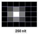
로컬 디밍 방법은 백라이트 발광면을 다수의 블록으로 분할하여 영상이 밝은 블록의 백라이트 휘도를 높이는 반면, 영상이 상대적으로 어두운 블록의 백라이트 휘도를 낮춘다. 로컬 디밍 방법은 도 1a 내지 도 1c와 같이 백라이트 발광면의 블록 분할 수가 많아지면 더 정밀하게 백라이트 휘도를 제어할 수 있다. 반면에, 블록들의 분할 수가 증가하면 도 1a 내지 도 1c와 같이 한 블록의 휘도 기여도는 작아진다.The local dimming method divides the backlight emitting surface into a plurality of blocks to increase the backlight luminance of a block in which the image is bright, while lowering the backlight luminance of a block in which the image is relatively dark. In the local dimming method, as shown in FIGS. 1A to 1C, when the number of block divisions of the backlight emission surface increases, the backlight luminance may be more precisely controlled. On the other hand, as the number of divisions of blocks increases, the luminance contribution of one block decreases as shown in FIGS. 1A to 1C.
로컬 디밍의 블록별 디밍값은 공간 필터(Spatial filter)에 의해 결정될 수 있다. 공간 필터는 백라이트의 피크(peak) 휘도를 주변 블록으로 확산하여 백라이트 휘도의 공간 주파수를 낮춤으로써 원치 않는 헤일로 효과(halo effect)와 휘도 불균일(non-uniformity) 현상을 개선할 수 있다. 종래의 공간 필터는 마스크 크기와 마스크 계수값이 고정되어 있다. 이 때문에 종래의 공간 필터를 이용한 로컬 디밍 방법은 백라이트 발광면의 블록 분할 수가 증가하면 백라이트 휘도가 낮아지는 문제가 있고, 이로 인하여 표시영상을 어둡게 보이게 한다.
The block-specific dimming value of the local dimming may be determined by a spatial filter. The spatial filter can improve unwanted halo effects and luminance non-uniformity by lowering the spatial frequency of the backlight brightness by spreading the peak brightness of the backlight to neighboring blocks. In the conventional spatial filter, the mask size and the mask coefficient value are fixed. For this reason, the conventional dimming method using the spatial filter has a problem that the backlight brightness decreases when the number of block divisions of the backlight emitting surface increases, thereby making the display image dark.
본 발명은 로컬 디밍시에 발생하는 휘도 저하 문제를 개선할 수 있는 로컬 디밍 방법과 이를 이용한 액정표시장치를 제공한다.
The present invention provides a local dimming method and a liquid crystal display device using the same that can improve the luminance degradation problem occurring when local dimming.
본 발명의 로컬 디밍 방법은 입력 영상을 N×M(N 및 M 각각은 n 보다 큰 양의 정수) 블록으로 분할하는 단계; 상기 블록들 각각의 평균 휘도를 정의하는 블록별 대표값을 결정하는 단계; 상기 입력 영상을 분석하는 단계; n×n(n은 3 보다 크고 10 이하의 양의 정수) 크기의 공간 필터 마스크를 설정하고, 상기 입력 영상의 분석 결과에 의해 상기 입력 영상이 어두운 영상으로 판단될 때 상기 공간 필터 마스크에서 0 보다 큰 계수들의 개수를 증가시키는 반면에, 상기 입력 영상의 분석 결과에 의해 상기 입력 영상이 밝은 영상으로 판단될 때 상기 공간 필터의 마스크에서 0 보다 큰 계수들의 개수를 감소시키는 단계; 및 상기 블록별 대표값에 상기 공간 필터의 계수를 곱하여 블록별 디밍값을 결정하는 단계를 포함한다.The local dimming method of the present invention comprises the steps of: dividing an input image into N × M blocks (where N and M are each positive integers greater than n); Determining a representative value for each block defining an average luminance of each of the blocks; Analyzing the input image; Set a spatial filter mask of size n × n (n is a positive integer greater than 3 and less than or equal to 10), and when the input image is determined to be a dark image based on the analysis result of the input image, Increasing the number of large coefficients, while decreasing the number of coefficients greater than zero in the mask of the spatial filter when the input image is determined to be a bright image by an analysis result of the input image; And determining a dimming value for each block by multiplying the representative value for each block by the coefficient of the spatial filter.
상기 로컬 디밍 방법은 상기 입력 영상의 분석 결과에 의해 상기 입력 영상이 어두운 영상으로 판단될 때 상기 공간 필터 마스크의 계수들을 높은 값으로 선택하는 반면에, 상기 입력 영상의 분석 결과에 의해 상기 입력 영상이 밝은 영상으로 판단될 때 상기 공간 필터 마스크의 계수들을 상대적으로 낮은 값으로 선택하는 단계를 더 포함한다.The local dimming method selects the coefficients of the spatial filter mask to a high value when the input image is determined to be a dark image by the analysis result of the input image, whereas the input image is determined by the analysis result of the input image. The method may further include selecting coefficients of the spatial filter mask to a relatively low value when judged to be a bright image.
상기 입력 영상을 분석하는 단계는 상기 입력 영상의 히스토그램과 평균화상레벨(APL) 중 어느 하나를 계산하는 단계; 및 상기 히스토그램과 평균화상레벨(APL) 중 어느 하나에 기초하여 상기 입력 영상의 밝은 정도를 판단하는 단계를 포함한다.The analyzing of the input image may include calculating one of a histogram and an average image level (APL) of the input image; And determining the brightness of the input image based on one of the histogram and the average image level APL.
상기 로컬 디밍 방법은 시간 필터를 이용하여 상기 블록별 디밍값을 다수의 프레임기간 동안 분산하는 단계를 더 포함한다.The local dimming method further includes distributing the block-specific dimming values for a plurality of frame periods using a time filter.
상기 로컬 디밍 방법은 백라이트 발광면을 상기 N×M 블록으로 가상 분할하는 단계; 및 상기 블록별 디밍값에 따라 백라이트 발광면의 휘도를 상기 블록별로 제어하는 단계를 더 포함한다.The local dimming method may further include: virtually dividing a backlight emitting surface into the N × M blocks; And controlling the luminance of the backlight emitting surface for each block according to the dimming value for each block.
본 발명의 액정표시장치는 액정표시패널; N×M(N 및 M 각각은 n 보다 큰 양의 정수) 블록으로 분할된 백라이트 발광면을 포함하여 상기 액정표시패널에 빛을 조사하는 백라이트 유닛; 상기 백라이트 유닛의 광원들을 상기 백라이트 발광면에서 분할된 블록별로 제어하는 백라이트 구동부; 및 입력 영상의 분석 결과에 따라 상기 백라이트 발광면의 블록별 휘도를 제어하는 로컬 디밍 회로를 포함한다.The liquid crystal display device of the present invention comprises a liquid crystal display panel; A backlight unit for irradiating light to the liquid crystal display panel including a backlight light emitting surface divided into N × M blocks (N and M each being positive integers greater than n); A backlight driver configured to control light sources of the backlight unit for each block divided in the backlight emission surface; And a local dimming circuit for controlling luminance of each block of the backlight emission surface according to an analysis result of the input image.
상기 로컬 디밍 회로는 상기 입력 영상을 N×M(N 및 M 각각은 n 보다 큰 양의 정수) 블록으로 분할하는 블록 분할부; 상기 블록들 각각의 평균 휘도를 정의하는 블록별 대표값을 결정하는 블록별 대표값 결정부; 가변 가능한 마스크 계수를 상기 블록별 대표값 결정부에 곱하여 블록별 디밍값을 출력하는 공간 필터; 상기 입력 영상을 분석하는 영상 분석부; 및 n×n(n은 3 보다 크고 10 이하의 양의 정수) 크기의 공간 필터 마스크를 설정하고, 상기 입력 영상의 분석 결과에 의해 상기 입력 영상이 어두운 영상으로 판단될 때 상기 공간 필터 마스크에서 0 보다 큰 계수들의 개수를 증가시키는 반면에, 상기 입력 영상의 분석 결과에 의해 상기 입력 영상이 밝은 영상으로 판단될 때 상기 공간 필터의 마스크에서 0 보다 큰 계수들의 개수를 감소시시키는 공간 필터 계수 선택부를 포함한다.
The local dimming circuit may include: a block dividing unit dividing the input image into N × M blocks, each of N and M being a positive integer greater than n; A block-specific representative value determining unit that determines a block-specific representative value defining an average luminance of each of the blocks; A spatial filter which multiplies a variable mask coefficient by the representative value determining unit for each block and outputs a dimming value for each block; An image analyzer configured to analyze the input image; And setting a spatial filter mask having a size of n × n (n is a positive integer greater than 3 and less than or equal to 10), and when the input image is determined to be a dark image by a result of analysis of the input image, 0 in the spatial filter mask. While increasing the number of larger coefficients, the spatial filter coefficient selector for reducing the number of coefficients greater than 0 in the mask of the spatial filter when the input image is determined to be a bright image by the analysis result of the input image Include.
본 발명은 점등되는 백라이트 유닛에서 주변 광원의 개수가 작은 어두운 영상이 입력될 때 공간 필터의 계수가 설정되는 마스크 크기를 크게 하는 반면에, 주변 광원의 개수가 많은 밝은 영상이 입력될 때 공간 필터의 계수가 설정되는 마스크 크기를 작게 조절한다. 그 결과, 본 발명은 로컬 디밍시에 블록 분할 수를 증가할 때 발생하는 휘도 저하를 방지할 수 있다.
According to the present invention, when a dark image having a small number of ambient light sources is input in a lit backlight unit, the mask size at which the coefficient of the spatial filter is set is increased. Reduce the mask size at which the coefficient is set. As a result, the present invention can prevent a decrease in luminance that occurs when the number of block divisions is increased during local dimming.
도 1a 내지 도 1c는 3×3 마스크를 갖는 공간 필터를 통해 한 블록의 피크 휘도를 3×3 블록들로 확산하고 블록 크기별 휘도를 예시한 도면들이다.
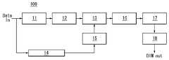
도 2는 본 발명의 실시예에 따른 로컬 디밍 회로를 보여 주는 블록도이다.
도 3a는 어두운 영상이 입력될 때 액정표시패널에 표시되는 영상과 로컬 디밍시의 점등 블록을 나타내는 도면이다.
도 3b는 밝은 영상이 입력될 때 액정표시패널에 표시되는 영상과 로컬 디밍시의 점등 블록을 나타내는 도면이다.
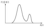
도 4a는 도 3a와 같은 영상의 히스토그램을 나타내는 도면이다.
도 4b는 도 3b와 같은 영상의 히스토그램을 나타내는 도면이다.
도 5a는 공간 필터의 마스크와 그 마스크의 블록별로 할당된 계수를 나타내는 도면이다.
도 5b는 도 3a와 같이 어두운 영상이 입력될 때 높은 값으로 선택되는 공간 필터의 마스크 계수를 나타내는 도면이다.
도 5c는 도 3b와 같이 밝은 영상이 입력될 때 낮은 값으로 선택되는 공간 필터의 마스크 계수를 나타내는 도면이다.
도 6은 공간 필터의 동작을 나타내는 도면이다.
도 7은 본 발명의 실시예에 따른 액정표시장치를 나타내는 블록도이다.1A to 1C are diagrams illustrating the luminance of each block by spreading the peak luminance of one block into 3x3 blocks through a spatial filter having a 3x3 mask.
2 is a block diagram illustrating a local dimming circuit according to an embodiment of the present invention.
3A is a diagram illustrating an image displayed on a liquid crystal display panel when a dark image is input, and a lighting block when local dimming is performed.
FIG. 3B is a diagram illustrating an image displayed on a liquid crystal display panel when a bright image is input and a lighting block during local dimming.
4A is a diagram illustrating a histogram of an image as illustrated in FIG. 3A.
4B is a diagram illustrating a histogram of an image as illustrated in FIG. 3B.
5A is a diagram illustrating a mask of a spatial filter and coefficients allocated for each block of the mask.
FIG. 5B is a diagram illustrating mask coefficients of a spatial filter selected to a high value when a dark image is input as shown in FIG. 3A.
FIG. 5C is a diagram illustrating mask coefficients of a spatial filter selected as a low value when a bright image is input as shown in FIG. 3B.
6 is a diagram illustrating the operation of a spatial filter.
7 is a block diagram illustrating a liquid crystal display according to an exemplary embodiment of the present invention.
이하 첨부된 도면을 참조하여 본 발명에 따른 바람직한 실시예들을 상세히 설명한다. 명세서 전체에 걸쳐서 동일한 참조번호들은 실질적으로 동일한 구성요소들을 의미한다. 이하의 설명에서, 본 발명과 관련된 공지 기능 혹은 구성에 대한 구체적인 설명이 본 발명의 요지를 불필요하게 흐릴 수 있다고 판단되는 경우, 그 상세한 설명을 생략한다.DETAILED DESCRIPTION OF THE PREFERRED EMBODIMENTS Reference will now be made in detail to the preferred embodiments of the present invention, examples of which are illustrated in the accompanying drawings. Like reference numerals throughout the specification denote substantially identical components. In the following description, a detailed description of known functions and configurations incorporated herein will be omitted when it may make the subject matter of the present invention rather unclear.
도 2를 참조하면, 로컬 디밍 회로(100)는 블록 분할부(11), 블록별 대표값 결정부(12), 영상 분석부(14), 공간 필터 계수 선택부(15), 공간 필터(13), 시간 필터(temporal filter, 16), 디밍값 결정부(17), 및 광원 제어부(18)를 포함한다.Referring to FIG. 2, the
블록 분할부(11)는 공간 필터의 마스크 분할수보다 많은 N×M(N 및 M 각각은 n 보다 큰 양의 정수) 블록으로 가상 분할한다. 영상의 블록 분할 형태에 대응하여 백라이트 발광면은 N×M으로 분할된다.The
블록별 대표값 결정부(12)는 블록별 대표값을 결정한다. 블록별 대표값은 1 프레임 입력 영상의 평균값 또는 평균화상레벨(Average Picture Level, APL)로 산출될 수 있다. 입력 영상의 평균값은 픽셀의 RGB 값들 중에서 가장 높은 값들의 평균값이며, 평균화상레벨(APL)은 픽셀들의 휘도값(Y)의 평균값이다.The block representative
영상 분석부(14)는 1 프레임 영상에 대하여 히스토그램 또는 평균화상레벨(APL)을 계산하고, 그 히스토그램 분석 결과 또는 평균화상레벨(APL)을 공간 필터 계수 선택부(15)에 공급한다. 도 3a과 같이 화면에서 특정 부분만 밝고 배경 휘도가 낮은 영상이 입력될 때 그 영상의 히스토그램은 도 4a와 같이 계산될 수 있다. 도 3b와 같이 화면 전체가 밝은 영상이 입력될 때 그 영상의 히스토그램은 도 4b와 같이 계산될 수 있다. 또한, 도 3a과 같이 화면에서 특정 부분만 밝고 배경 휘도가 낮은 영상이 입력될 때 평균화상레벨(APL)은 상대적으로 낮은 값으로 계산되고, 도 3b와 같이 화면 전체가 밝은 영상이 입력될 때 그 영상의 평균화상레벨(APL)은 높은 값으로 계산된다.The
도 4a의 히스토그램은 밝은 계조의 픽셀 데이터 개수가 적은 반면 배경 이미지에 표시되는 어두운 계조의 픽셀 데이터들이 많기 때문에 전체적으로 어두운 영상을 지시한다. 도 3a 및 도 4a와 같은 어두운 영상에서, 백라이트 발광면의 블록들 각각을 광원이라 할 때 공간 필터에 의해 주변 광원들로 확산되어 점등되는 주변 광원들의 개수가 많아진다.The histogram of FIG. 4A indicates a dark image as a whole because the number of pixel data of light gray is small and the pixel data of dark gray displayed on the background image is large. In the dark images of FIGS. 3A and 4A, when each of the blocks of the backlight emitting surface is a light source, the number of ambient light sources that are diffused and lit by the ambient light sources by the spatial filter increases.
이에 비하여, 도 3b와 같이 배경 이미지가 중간 계조로 표시되고 특정 부분이 밝은 경우에 히스토그램은 도 4b와 같이 계산될 수 있다. 도 4b의 히스토그램에는 배경 이미지에서 중간 계조의 픽셀들이 넓게 분산되고 그 개수가 많고 높은 화이트 계조의 픽셀들이 상대적으로 적은 개수로 분포되어 있다. 따라서, 도 4b와 같은 히스토그램은 전체적으로 밝은 영상을 지시한다. 도 3b 및 도 4b와 같은 밝은 영상에서, 백라이트 발광면의 블록들 각각을 광원이라 할 때 공간 필터에 의해 주변 광원들로 확산되어 점등되는 주변 광원들의 개수가 적다.In contrast, when the background image is displayed in halftone and the specific part is bright as shown in FIG. 3B, the histogram may be calculated as shown in FIG. 4B. In the histogram of FIG. 4B, pixels of a middle gray scale are widely distributed in a background image, and a large number of pixels of a high white gray scale are distributed in a relatively small number. Therefore, the histogram as shown in FIG. 4B generally indicates a bright image. In the bright images of FIGS. 3B and 4B, when each of the blocks of the backlight emitting surface is a light source, the number of ambient light sources that are diffused and lit by the ambient light sources by the spatial filter is small.
공간 필터 계수 선택부(15)는 n×n(n은 3 보다 크고 10 이하의 양의 정수) 크기의 공간 필터 마스크의 계수를 선택한다. 이하에서 공간 필터의 마스크 크기는 5×5로 설명되나 이에 한정되지 않는다는 것에 주의하여야 한다. 공간 필터 계수 선택부(15)는 영상 분석부(14)로부터의 히스토그램 분석 결과 또는 평균화상레벨(APL)을 입력 받아, 그 히스토그램 분석 결과 또는 평균화상레벨(APL)에 따라 가변되는 공간 필터의 마스크 계수를 선택한다.The spatial
공간 필터 계수 선택부(15)는 이전 프레임 영상의 히스토그램과 현재 프레임 영상의 히스토그램을 비교하여 현재 프레임 영상의 히스토그램에서 밝은 픽셀들의 개수가 작아지면 로컬 디밍 블록(또는 백라이트 발광면 블록)의 점등 광원 개수가 많아지도록 도 5b와 같이 0 보다 큰 계수를 갖는 공간 필터의 마스크 크기를 크게 한다. 반면에, 공간 필터 계수 선택부(15)는 이전 프레임 영상의 히스토그램과 현재 프레임 영상의 히스토그램을 비교하여 현재 프레임 영상의 히스토그램에서 밝은 픽셀들의 개수가 더 많아지면 로컬 디밍 블록의 점등 광원 개수가 상대적으로 더 작아지도록 도 5c와 같이 0 보다 큰 계수를 갖는 공간 필터의 마스크 크기를 작게 한다.The spatial
다른 실시예로서, 공간 필터 계수 선택부(15)는 소정의 기준 평균화상레벨(APL)과 현재 프레임 영상의 평균화상레벨(APL)을 비교하여 현재 프레임 영상의 평균화상레벨(APL)이 기준 평균화상레벨(APL) 보다 낮으면 로컬 디밍 블록의 점등 광원 개수가 많아지도록 도 5b와 같이 0 보다 큰 계수를 갖는 공간 필터의 마스크 크기를 크게 한다. 반면에, 공간 필터 계수 선택부(15)는 기준 평균화상레벨(APL)과 현재 프레임 영상의 평균화상레벨(APL)을 비교하여 현재 프레임 영상의 평균화상레벨(APL)의 평균화상레벨(APL)이 기준 평균화상레벨(APL) 보다 높으면 로컬 디밍 블록의 점등 광원 개수가 상대적으로 더 작아지도록 도 5c와 같이 0 보다 큰 계수를 갖는 공간 필터의 마스크 크기를 작게 한다.In another exemplary embodiment, the spatial
공간 필터의 마스크는 도 5a와 같은 5×5 마스크로 설정될 수 있고 마스크의 블록별로 할당된 계수는 h1~h25이다. 공간 필터 계수 선택부(15)는 도 3a와 같이 어두운 영상이 입력될 때 0 보다 높은 계수를 갖는 마스크의 크기를 크게 하여 로컬 디밍 점등 블록 점등 블록 개수를 증가시키는 반면, 도 3b와 같이 밝은 영상이 입력될 때 마스크의 가장자리에 할당된 계수를 0으로 치환하여 0 보다 높은 계수를 갖는 마스크 크기를 작게 하여 로컬 디밍 점등 블록 개수를 감소시킨다.The mask of the spatial filter may be set to a 5 × 5 mask as shown in FIG. 5A, and coefficients allocated for each block of the mask are h1 to h25. The spatial
공간 필터 계수 선택부(15)는 이전 프레임 영상의 히스토그램과 현재 프레임 영상의 히스토그램을 비교하여 현재 프레임 영상의 히스토그램에서 밝은 픽셀들의 개수가 작아지면 점등 블록의 휘도를 높이기 위하여 도 5b와 같이 공간 필터의 마스크 계수를 높인다. 반면에, 공간 필터 계수 선택부(15)는 이전 프레임 영상의 히스토그램과 현재 프레임 영상의 히스토그램을 비교하여 현재 프레임 영상의 히스토그램에서 밝은 픽셀들의 개수가 더 많아지면 점등 블록의 휘도를 낮추기 위하여 도 5c와 같이 공간 필터의 마스크 계수를 낮춘다.The spatial
다른 실시예로서, 공간 필터 계수 선택부(15)는 소정의 기준 평균화상레벨(APL)과 현재 프레임 영상의 평균화상레벨(APL)을 비교하여 현재 프레임 영상의 평균화상레벨(APL)이 기준 평균화상레벨(APL) 보다 낮으면 점등 블록의 휘도를 높이기 위하여 도 5b와 같이 공간 필터의 마스크 계수를 높은 값으로 선택한다. 반면에, 공간 필터 계수 선택부(15)는 기준 평균화상레벨(APL)과 현재 프레임 영상의 평균화상레벨(APL)을 비교하여 현재 프레임 영상의 평균화상레벨(APL)의 평균화상레벨(APL)이 기준 평균화상레벨(APL) 보다 높으면 점등 블록의 휘도를 낮추기 위하여 도 5c와 같이 공간 필터의 마스크 계수를 낮은 값으로 선택한다.In another exemplary embodiment, the spatial
공간 필터 계수 선택부(15)는 전술한 바와 같이 도 3a와 같은 어두운 영상이 입력될 때 공간 필터의 마스크 계수를 높은 값으로 선택하여 점등 블록의 휘도를 높이는 반면, 도 3b와 같이 밝은 영상이 입력될 때 공간 필터의 마스크 계수를 상대적으로 낮은 값으로 선택하여 점등 블록의 휘도를 낮춘다.As described above, the spatial
공간 필터(13)는 블록별 대표값 결정부(12)로부터 입력된 블록별 대표값(x1~x25)에 공간 필터 계수 선택부(15)에 의해 선택된 마스크 계수를 곱하여 그 결과로 생성된 블록별 디밍값을 시간 필터(16)에 공급한다. 공간 필터(13)의 출력(g(x13))은 수학식 1과 같고 이를 도식화하면 도 6과 같이 나타낼 수 있다.The

시간 필터(16)는 공간 필터(13)로부터 입력된 블록별 디밍값을 다수의 프레임기간 동안 분산시켜 플리커를 예방한다. 시간 필터(16)는 IIR 필터(Infinite-Impulse-Response Filter) 또는 FIR 필터(Finite Impulse Response Filter)를 이용하여 블록별 디밍값을 시간적으로 분산시킬 수 있다. 일 예로, 시간 필터(16)는 본원 출원인에 의해 기출원된 대한민국 출원 10-2008-0007282(2008. 01. 23)으로 적용될 수 있고, 공지된 어떠한 시간 필터로도 구현될 수 있다.The
디밍값 결정부(17)는 시간 필터(16)로부터 입력된 블록별 디밍값을 SPI(Serial Peripheral Interface) 포맷의 데이터로 코딩하여 광원 제어부(18)의 마이크로 콘트롤 유닛(Micro Control Unit, MCU)에 공급한다.The dimming
광원 제어부(18)는 디밍값 결정부(17)로부터 입력되는 디밍값(DIMim)에 따라 듀티비가 가변되는 펄스폭 변조(Pulse Width Modulation, PWM)로 백라이트 유닛(300)의 광원들을 블록별로 개별 제어한다. 펄스폭 변조 신호(PWM)는 광원 구동부에 입력되어 광원들의 점등 및 소등의 비율을 제어하며, 그 듀티비(duty ratio %)는 광원 제어부(18)에 입력되는 블록별 디밍값에 따라 결정진다. 블록별 디밍값이 클수록 펄스폭 변조 신호(PWM)의 듀티비가 커지는 반면, 블록별 디밍값이 작아지면 펄스폭 변조 신호(PWM)의 듀티비도 작아진다.The
도 7은 본 발명의 실시예에 따른 액정표시장치를 나타낸다.7 shows a liquid crystal display device according to an embodiment of the present invention.
도 7을 참조하면, 본 발명의 액정표시장치는 액정표시패널(200), 액정표시패널(200)의 데이터라인들(201)을 구동하기 위한 소스 구동부(210), 액정표시패널(200)의 게이트라인들(202)을 구동하기 위한 게이트 구동부(220), 소스 구동부(210)와 게이트 구동부(220)를 제어하는 타이밍 콘트롤러(230), 액정표시패널(200)에 빛을 조사하는 백라이트 유닛(300), 백라이트 유닛(300)의 광원들을 구동하기 위한 광원 구동부(310), 및 로컬 디밍을 제어하기 위한 로컬 디밍 회로(100)를 구비한다.Referring to FIG. 7, the liquid crystal display of the present invention may include a liquid
액정표시패널(200)은 두 장의 유리기판 사이에 액정층이 형성된다. 액정표시패널(200)에는 데이터라인들(201)과 게이트라인들(202)의 교차 구조에 의해 액정셀들이 매트릭스 형태로 배치된다. 액정표시패널(200)의 박막트랜지스터(Thin Film Transistor, 이하 "TFT"라 함) 어레이 기판에는 데이터라인들(201), 게이트라인들(202), TFT들, TFT들에 접속된 액정셀의 화소전극, 및 스토리지 커패시터 등이 형성된다.In the liquid
액정표시패널(200)의 컬러필터 기판에는 블랙매트릭스, 컬러필터 및 공통전극이 형성된다.A black matrix, a color filter, and a common electrode are formed on the color filter substrate of the liquid
본 발명의 액정표시장치는 TN(Twisted Nematic) 모드와 VA(Vertical Alignment) 모드와 같은 수직전계 구동방식이나 IPS(In Plane Switching) 모드와 FFS(Fringe Field Switching) 모드와 같은 수평전계 구동방식으로 구현될 수 있다.The liquid crystal display of the present invention is implemented in a vertical electric field driving method such as twisted nematic (TN) mode and a vertical alignment (VA) mode, or a horizontal electric field driving method such as IPS (In Plane Switching) mode and FFS (Fringe Field Switching) mode. Can be.
액정표시패널(200)의 화소 어레이와 그와 대향하는 백라이트 유닛(300)의 발광면은 로컬 디밍을 위하여 N×N 블록들로 가상 분할된다. 블록들 각각은 i×j(i 및 j는 2 이상의 양의 정수) 개의 픽셀들과, 그 픽셀들에 빛을 조사하는 백라이트 발광면을 포함한다. 픽셀들 각각은 3 원색 이상의 서브픽셀들을 포함하며, 서브픽셀은 액정셀을 포함한다.The pixel array of the liquid
타이밍 콘트롤러(230)는 외부의 호스트 시스템으로부터 타이밍신호들(Vsync, Hsync, DE, DCLK)을 입력받아 디지털 비디오 데이터(RGB)를 소스 구동부(210)에 공급한다. 타이밍신호들(Vsync, Hsync, DE, DCLK)은 수직 동기신호(Vsync), 수평 동기신호(Hsync), 데이터 인에이블신호(DE), 도트 클럭신호(DCLK) 등을 포함한다. 타이밍 콘트롤러(230)는 호스트 시스템으로부터의 타이밍신호들(Vsync, Hsync, DE, DCLK)에 기초하여 소스 구동부(210)와 게이트 구동부(220)의 동작 타이밍을 제어하기 위한 타이밍 제어신호들(DDC, GDC)을 발생한다. 타이밍 콘트롤러(230)는 호스트 시스템으로부터 입력되는 입력 영상의 디지털 비디오 데이터(RGB)를 로컬 디밍 회로(100)에 공급하고, 로컬 디밍 회로(100)에 의해 변조된 디지털 비디오 데이터들(R'G'B')을 소스 구동부(210)에 공급할 수 있다.The
소스 구동부(210)는 타이밍 콘트롤러(230)의 제어 하에 디지털 비디오 데이터(R'G'B')를 래치한다. 그리고 소스 구동부(210)는 정극성/부극성 감마보상전압을 이용하여 디지털 비디오 데이터(R'G'B')를 정극성/부극성 아날로그 데이터전압으로 변환하여 데이터라인들(201)에 공급한다. 게이트 구동부(220)는 데이터라인들(201) 상의 데이터전압과 동기되는 게이트펄스(또는 스캔펄스들)을 게이트라인들순차적으로 공급한다.The
백라이트 유닛(300)은 액정표시패널(200)의 아래에 배치된다. 백라이트 유닛(300)은 광원 구동부(310)에 의해 블록별로 개별 제어되는 다수의 광원들을 포함하여 액정표시패널(200)로 균일하게 빛을 조사한다. 백라이트 유닛(300)은 직하형(direct type) 백라이트 유닛 또는, 에지형(edge type) 백라이트 유닛으로 구현될 수 있다. 백라이트 유닛의 광원은 LED(Light Emitting Diode)와 같은 점광원으로 구현될 수 있다.The
광원 구동부(310)는 로컬 디밍 회로(100)로부터 입력되는 블록별 디밍값(DIM)에 따라 듀티비가 가변되는 PWM로 백라이트 유닛(300)의 광원들을 블록별로 개별 구동하여 로컬 디밍 회로(100)의 제어 하에 백라이트 점등 블록의 휘도를 제어한다.The
로컬 디밍 회로(100)는 도 1과 같이 구현되어 입력 영상의 분석 결과에 따라 공간 필터의 마스크 계수를 선택하여 블록별 대표값을 조절한다. 로컬 디밍 회로(100)는 도시하지 않은 룩업 테이블을 이용하여 낮은 백라이트 휘도를 보상하고 데이터 계조의 포화를 방지하기 위하여 타이밍 콘트롤러(230)로부터 입력된 디지털 비디오 데이터들(RGB)을 변조하고 변조된 데이터들(R'G'B')를 타이밍 콘트롤러(230)에 공급할 수 있다.The
이상 설명한 내용을 통해 당업자라면 본 발명의 기술사상을 일탈하지 아니하는 범위에서 다양한 변경 및 수정이 가능함을 알 수 있을 것이다. 따라서, 본 발명의 기술적 범위는 명세서의 상세한 설명에 기재된 내용으로 한정되는 것이 아니라 특허 청구의 범위에 의해 정하여져야만 할 것이다.
It will be apparent to those skilled in the art that various modifications and variations can be made in the present invention without departing from the spirit or scope of the invention. Therefore, the technical scope of the present invention should not be limited to the contents described in the detailed description of the specification, but should be defined by the claims.
11 : 블록 분할부12 : 블록별 대표값 결정부
13 : 공간 필터14 : 영상 분석부
15 : 공간 필터 계수 선택부16 : 시간 필터
17 : 디밍값 결정부18 : 광원 제어부
100 : 로컬 디밍 회로200 : 액정표시패널
300 : 백라이트 유닛11: block division unit 12: block representative value determination unit
13: spatial filter 14: image analysis unit
15: spatial filter coefficient selector 16: time filter
17 dimming
100: local dimming circuit 200: liquid crystal display panel
300: backlight unit
Claims (10)
Translated fromKorean상기 블록들 각각의 평균 휘도를 정의하는 블록별 대표값을 결정하는 단계;
상기 입력 영상을 분석하는 단계;
n×n(n은 3 보다 크고 10 이하의 양의 정수) 크기의 공간 필터 마스크를 설정하고, 상기 입력 영상의 분석 결과에 의해 상기 입력 영상이 어두운 영상으로 판단될 때 상기 공간 필터 마스크에서 0 보다 큰 계수들의 개수를 증가시키는 반면에, 상기 입력 영상의 분석 결과에 의해 상기 입력 영상이 밝은 영상으로 판단될 때 상기 공간 필터의 마스크에서 0 보다 큰 계수들의 개수를 감소시키는 단계; 및
상기 블록별 대표값에 상기 공간 필터의 계수를 곱하여 블록별 디밍값을 결정하는 단계를 포함하는 것을 특징으로 하는 로컬 디밍 방법.
Dividing the input image into N × M blocks (where N and M are each positive integers greater than n);
Determining a representative value for each block defining an average luminance of each of the blocks;
Analyzing the input image;
Set a spatial filter mask of size n × n (n is a positive integer greater than 3 and less than or equal to 10), and when the input image is determined to be a dark image based on the analysis result of the input image, Increasing the number of large coefficients, while decreasing the number of coefficients greater than zero in the mask of the spatial filter when the input image is determined to be a bright image by an analysis result of the input image; And
And determining the dimming value for each block by multiplying the representative value for each block by the coefficient of the spatial filter.
상기 입력 영상의 분석 결과에 의해 상기 입력 영상이 어두운 영상으로 판단될 때 상기 공간 필터 마스크의 계수들을 높은 값으로 선택하는 반면에, 상기 입력 영상의 분석 결과에 의해 상기 입력 영상이 밝은 영상으로 판단될 때 상기 공간 필터 마스크의 계수들을 상대적으로 낮은 값으로 선택하는 단계를 더 포함하는 것을 특징으로 하는 로컬 디밍 방법.
The method of claim 1,
When the input image is determined to be a dark image by the analysis result of the input image, coefficients of the spatial filter mask are selected to a high value, while the input image may be determined to be a bright image by the analysis result of the input image. And selecting the coefficients of the spatial filter mask to a relatively low value.
상기 입력 영상을 분석하는 단계는,
상기 입력 영상의 히스토그램과 평균화상레벨(APL) 중 어느 하나를 계산하는 단계; 및
상기 히스토그램과 평균화상레벨(APL) 중 어느 하나에 기초하여 상기 입력 영상의 밝은 정도를 판단하는 단계를 포함하는 것을 특징으로 하는 로컬 디밍 방법.
The method of claim 1,
Analyzing the input image,
Calculating one of a histogram and an average image level (APL) of the input image; And
And determining the brightness of the input image based on one of the histogram and the average image level (APL).
시간 필터를 이용하여 상기 블록별 디밍값을 다수의 프레임기간 동안 분산하는 단계를 더 포함하는 것을 특징으로 하는 로컬 디밍 방법.
The method of claim 1,
And dividing the block-specific dimming values for a plurality of frame periods by using a temporal filter.
백라이트 발광면을 상기 N×M 블록으로 가상 분할하는 단계; 및
상기 블록별 디밍값에 따라 백라이트 발광면의 휘도를 상기 블록별로 제어하는 단계를 더 포함하는 것을 특징으로 하는 로컬 디밍 방법.
The method according to any one of claims 1 to 4,
Virtually dividing a backlight emitting surface into the N × M blocks; And
And controlling the luminance of the backlight emitting surface for each block according to the dimming value for each block.
N×M(N 및 M 각각은 n 보다 큰 양의 정수) 블록으로 분할된 백라이트 발광면을 포함하여 상기 액정표시패널에 빛을 조사하는 백라이트 유닛;
상기 백라이트 유닛의 광원들을 상기 백라이트 발광면에서 분할된 블록별로 제어하는 백라이트 구동부; 및
입력 영상의 분석 결과에 따라 상기 백라이트 발광면의 블록별 휘도를 제어하는 로컬 디밍 회로를 포함하고,
상기 로컬 디밍 회로는,
상기 입력 영상을 N×M(N 및 M 각각은 n 보다 큰 양의 정수) 블록으로 분할하는 블록 분할부;
상기 블록들 각각의 평균 휘도를 정의하는 블록별 대표값을 결정하는 블록별 대표값 결정부;
가변 가능한 마스크 계수를 상기 블록별 대표값 결정부에 곱하여 블록별 디밍값을 출력하는 공간 필터;
상기 입력 영상을 분석하는 영상 분석부; 및
n×n(n은 3 보다 크고 10 이하의 양의 정수) 크기의 공간 필터 마스크를 설정하고, 상기 입력 영상의 분석 결과에 의해 상기 입력 영상이 어두운 영상으로 판단될 때 상기 공간 필터 마스크에서 0 보다 큰 계수들의 개수를 증가시키는 반면에, 상기 입력 영상의 분석 결과에 의해 상기 입력 영상이 밝은 영상으로 판단될 때 상기 공간 필터의 마스크에서 0 보다 큰 계수들의 개수를 감소시시키는 공간 필터 계수 선택부를 포함하는 것을 특징으로 하는 액정표시장치.
A liquid crystal display panel;
A backlight unit for irradiating light to the liquid crystal display panel including a backlight light emitting surface divided into N × M blocks (N and M each being positive integers greater than n);
A backlight driver configured to control light sources of the backlight unit for each block divided in the backlight emission surface; And
Local dimming circuit for controlling the luminance of each block of the backlight emitting surface according to the analysis result of the input image,
The local dimming circuit,
A block dividing unit dividing the input image into N × M blocks, each of N and M being a positive integer greater than n;
A block-specific representative value determining unit that determines a block-specific representative value defining an average luminance of each of the blocks;
A spatial filter which multiplies a variable mask coefficient by the representative value determining unit for each block and outputs a dimming value for each block;
An image analyzer configured to analyze the input image; And
Set a spatial filter mask of size n × n (n is a positive integer greater than 3 and less than or equal to 10), and when the input image is determined to be a dark image based on the analysis result of the input image, While increasing the number of large coefficients, the spatial filter coefficient selection unit for reducing the number of coefficients greater than zero in the mask of the spatial filter when the input image is determined to be a bright image by the analysis result of the input image Liquid crystal display characterized in that.
상기 공간 필터 계수 선택부는,
상기 입력 영상의 분석 결과에 의해 상기 입력 영상이 어두운 영상으로 판단될 때 상기 공간 필터 마스크의 계수들을 높은 값으로 선택하는 반면에, 상기 입력 영상의 분석 결과에 의해 상기 입력 영상이 밝은 영상으로 판단될 때 상기 공간 필터 마스크의 계수들을 상대적으로 낮은 값으로 선택하는 단계를 더 포함하는 것을 특징으로 하는 액정표시장치.
The method according to claim 6,
The spatial filter coefficient selector,
When the input image is determined to be a dark image by the analysis result of the input image, coefficients of the spatial filter mask are selected to a high value, while the input image may be determined to be a bright image by the analysis result of the input image. And selecting the coefficients of the spatial filter mask to a relatively low value.
상기 영상 분석부는,
상기 입력 영상의 히스토그램과 평균화상레벨(APL) 중 어느 하나를 계산하고,
상기 히스토그램과 평균화상레벨(APL) 중 어느 하나에 기초하여 상기 입력 영상의 밝은 정도를 판단하는 것을 특징으로 하는 액정표시장치.
The method according to claim 6,
Wherein the image analyzing unit comprises:
Calculates one of a histogram and an average image level (APL) of the input image,
And determining the brightness of the input image based on one of the histogram and the average image level APL.
상기 공간 필터로부터 입력된 상기 블록별 디밍값을 다수의 프레임기간 동안 분산하는 시간 필터를 더 포함하는 것을 특징으로 하는 액정표시장치.
The method according to claim 6,
And a temporal filter for dispersing the dimming value for each block input from the spatial filter for a plurality of frame periods.
상기 로컬 디밍 회로는,
상기 블록별 디밍값에 근거하여 상기 백라이트 구동부를 제어하여 상기 백라이트 발광면의 블록별 휘도를 제어하는 백라이트 제어부를 더 포함하는 것을 특징으로 하는 액정표시장치.10. The method according to any one of claims 6 to 9,
The local dimming circuit,
And a backlight controller configured to control the backlight driving unit based on the dimming value of each block to control luminance of each block of the backlight emitting surface.
Priority Applications (4)
| Application Number | Priority Date | Filing Date | Title |
|---|---|---|---|
| KR1020100118265AKR101324453B1 (en) | 2010-11-25 | 2010-11-25 | Method of local dimming method and liquid crystal display using the same |
| US13/304,011US9595229B2 (en) | 2010-11-25 | 2011-11-23 | Local dimming method and liquid crystal display |
| CN201110401179.8ACN102479496B (en) | 2010-11-25 | 2011-11-25 | Local dimming method and liquid crystal display |
| TW100143449ATWI447698B (en) | 2010-11-25 | 2011-11-25 | Local dimming method and liquid crystal display |
Applications Claiming Priority (1)
| Application Number | Priority Date | Filing Date | Title |
|---|---|---|---|
| KR1020100118265AKR101324453B1 (en) | 2010-11-25 | 2010-11-25 | Method of local dimming method and liquid crystal display using the same |
Publications (2)
| Publication Number | Publication Date |
|---|---|
| KR20120056634A KR20120056634A (en) | 2012-06-04 |
| KR101324453B1true KR101324453B1 (en) | 2013-10-31 |
Family
ID=46092112
Family Applications (1)
| Application Number | Title | Priority Date | Filing Date |
|---|---|---|---|
| KR1020100118265AExpired - Fee RelatedKR101324453B1 (en) | 2010-11-25 | 2010-11-25 | Method of local dimming method and liquid crystal display using the same |
Country Status (4)
| Country | Link |
|---|---|
| US (1) | US9595229B2 (en) |
| KR (1) | KR101324453B1 (en) |
| CN (1) | CN102479496B (en) |
| TW (1) | TWI447698B (en) |
Families Citing this family (27)
| Publication number | Priority date | Publication date | Assignee | Title |
|---|---|---|---|---|
| US20170272694A1 (en)* | 2004-12-13 | 2017-09-21 | Zeppelin, Inc. | Mobile Phone with Status Memory |
| JP5323272B2 (en)* | 2011-02-09 | 2013-10-23 | 三菱電機株式会社 | LIGHT EMITTING CONTROL DEVICE AND METHOD, LIGHT EMITTING DEVICE, IMAGE DISPLAY DEVICE, PROGRAM, AND RECORDING MEDIUM |
| JP5837009B2 (en)* | 2012-09-26 | 2015-12-24 | キヤノン株式会社 | Display device and control method thereof |
| KR102050451B1 (en)* | 2013-09-23 | 2019-11-29 | 엘지디스플레이 주식회사 | Image display device and method for driving the same |
| CN104050934B (en)* | 2014-05-28 | 2016-03-23 | 京东方科技集团股份有限公司 | Backlight adjustment method, backlight adjustment system and display device |
| US9468065B2 (en)* | 2014-10-15 | 2016-10-11 | Texas Instruments Incorporated | Combined hybrid and local dimming control of light emitting diodes |
| CN106004666B (en)* | 2016-07-18 | 2018-11-13 | 恒大法拉第未来智能汽车(广东)有限公司 | Automobile head-up display system and display methods |
| JP6777485B2 (en)* | 2016-09-26 | 2020-10-28 | エルジー ディスプレイ カンパニー リミテッド | Image display device and image display method |
| CN106328071B (en)* | 2016-10-14 | 2018-09-11 | 京东方科技集团股份有限公司 | A kind of the local backlight light-dimming method and liquid crystal display of liquid crystal display |
| CN107240376A (en)* | 2017-07-07 | 2017-10-10 | 青岛海信电器股份有限公司 | Method for controlling backlight thereof, device and liquid crystal display |
| KR102552922B1 (en)* | 2018-07-09 | 2023-07-10 | 삼성디스플레이 주식회사 | Display apparatus and method of driving the same |
| CN108877694B (en)* | 2018-08-06 | 2021-08-31 | 深圳创维-Rgb电子有限公司 | A double-layer liquid crystal screen, backlight brightness control method, device and electronic equipment |
| US10802333B2 (en)* | 2018-08-21 | 2020-10-13 | Himax Technologies Limited | Local dimming system and method adaptable to a backlight of a display |
| US10600370B2 (en)* | 2018-08-22 | 2020-03-24 | Himax Technologies Limited | Local dimming system adaptable to a backlight of a display |
| WO2020112085A1 (en) | 2018-11-27 | 2020-06-04 | Hewlett-Packard Development Company, L.P. | Displays with dimming zones that change |
| CN111785223A (en)* | 2019-04-04 | 2020-10-16 | 海信视像科技股份有限公司 | Double-panel display device |
| CN112086073B (en)* | 2019-06-12 | 2022-02-25 | 奇景光电股份有限公司 | Area dimming system and method for backlighting of displays |
| CN110910840B (en)* | 2019-12-13 | 2021-01-26 | 京东方科技集团股份有限公司 | A liquid crystal display, its backlight adjustment method, and computer readable medium |
| US11562702B2 (en)* | 2020-03-31 | 2023-01-24 | Sharp Kabushiki Kaisha | Dimming unit, and liquid crystal display device |
| JP2021182070A (en)* | 2020-05-19 | 2021-11-25 | ラピスセミコンダクタ株式会社 | Display device and source driver |
| CN111508443B (en) | 2020-05-29 | 2021-08-24 | 京东方科技集团股份有限公司 | Display device and method and device for controlling backlight brightness thereof |
| KR102692173B1 (en)* | 2020-06-16 | 2024-08-06 | 주식회사 엘엑스세미콘 | Dimming value filter apparatus, image data processing apparatus and display device for controlling local dimming |
| CN114627823B (en)* | 2020-12-11 | 2024-06-04 | 纬联电子科技(中山)有限公司 | Liquid crystal display and picture display method |
| CN113554982B (en)* | 2021-07-19 | 2022-09-09 | 京东方科技集团股份有限公司 | Method, system and display panel for pixel brightness compensation of display panel |
| CN116264060A (en)* | 2021-12-15 | 2023-06-16 | 群创光电股份有限公司 | Light source driving circuit and light source driving method |
| CN114420059B (en)* | 2021-12-31 | 2023-12-12 | 海宁奕斯伟集成电路设计有限公司 | Backlight control method and device and display equipment |
| CN114420061B (en)* | 2022-01-27 | 2023-05-23 | 深圳Tcl数字技术有限公司 | Screen brightness adjusting method and device, storage medium and display device |
Citations (3)
| Publication number | Priority date | Publication date | Assignee | Title |
|---|---|---|---|---|
| KR20090126337A (en)* | 2008-06-04 | 2009-12-09 | 삼성전자주식회사 | A light source local dimming driving method, a light source device for performing the same, and a display device having the light source device |
| KR20100011247A (en)* | 2008-07-24 | 2010-02-03 | 전자부품연구원 | Apparatus and method for compensating brightness of back light |
| KR20100048391A (en)* | 2008-10-31 | 2010-05-11 | 엘지전자 주식회사 | An image display device |
Family Cites Families (8)
| Publication number | Priority date | Publication date | Assignee | Title |
|---|---|---|---|---|
| JP2004004532A (en)* | 2002-03-25 | 2004-01-08 | Sharp Corp | Video display device |
| KR20090044292A (en)* | 2007-10-31 | 2009-05-07 | 삼성전자주식회사 | Display device and driving method thereof |
| US8917293B2 (en)* | 2008-06-27 | 2014-12-23 | Sharp Kabushiki Kaisha | Control device for liquid crystal display device, liquid crystal display device, method for controlling liquid crystal display device, program, and storage medium |
| KR101537418B1 (en)* | 2009-04-01 | 2015-07-17 | 엘지디스플레이 주식회사 | Liquid crystal display and driving method thereof |
| KR101294851B1 (en)* | 2009-04-01 | 2013-08-08 | 엘지디스플레이 주식회사 | Liquid crystal display and driving method of thereof |
| EP2284827A1 (en)* | 2009-07-15 | 2011-02-16 | Trident Microsystems (Far East) Ltd. | Backlight unit and control method for the same |
| BR112012008070A2 (en)* | 2009-07-29 | 2016-03-01 | Sharp Kk | image display device and image display method |
| JP5661336B2 (en)* | 2010-05-28 | 2015-01-28 | 日立マクセル株式会社 | Liquid crystal display |
- 2010
- 2010-11-25KRKR1020100118265Apatent/KR101324453B1/ennot_activeExpired - Fee Related
- 2011
- 2011-11-23USUS13/304,011patent/US9595229B2/enactiveActive
- 2011-11-25CNCN201110401179.8Apatent/CN102479496B/ennot_activeExpired - Fee Related
- 2011-11-25TWTW100143449Apatent/TWI447698B/ennot_activeIP Right Cessation
Patent Citations (3)
| Publication number | Priority date | Publication date | Assignee | Title |
|---|---|---|---|---|
| KR20090126337A (en)* | 2008-06-04 | 2009-12-09 | 삼성전자주식회사 | A light source local dimming driving method, a light source device for performing the same, and a display device having the light source device |
| KR20100011247A (en)* | 2008-07-24 | 2010-02-03 | 전자부품연구원 | Apparatus and method for compensating brightness of back light |
| KR20100048391A (en)* | 2008-10-31 | 2010-05-11 | 엘지전자 주식회사 | An image display device |
Also Published As
| Publication number | Publication date |
|---|---|
| US9595229B2 (en) | 2017-03-14 |
| TWI447698B (en) | 2014-08-01 |
| CN102479496B (en) | 2014-01-29 |
| CN102479496A (en) | 2012-05-30 |
| US20120133685A1 (en) | 2012-05-31 |
| TW201222516A (en) | 2012-06-01 |
| KR20120056634A (en) | 2012-06-04 |
Similar Documents
| Publication | Publication Date | Title |
|---|---|---|
| KR101324453B1 (en) | Method of local dimming method and liquid crystal display using the same | |
| US8890900B2 (en) | Liquid crystal display and method of local dimming thereof | |
| KR101295882B1 (en) | Liquid crystal display and local dimming control method of thereof | |
| KR101318444B1 (en) | Method of compensating pixel data and liquid crystal display | |
| US9189998B2 (en) | Backlight dimming method and liquid crystal display using the same | |
| US9852700B2 (en) | Liquid crystal display and method for driving the same | |
| KR101366964B1 (en) | Liquid crystal display | |
| US8400385B2 (en) | Method for enhancing an image displayed on an LCD device | |
| KR20110057506A (en) | LCD and Local Dimming Control Method | |
| JP2008139871A (en) | Liquid crystal display with area adaptive backlight | |
| KR20110068151A (en) | LCD and its driving method | |
| KR20090081290A (en) | LCD and Dimming Control Method | |
| US20110279482A1 (en) | System and Method for Controlling a Display Backlight | |
| KR20110038498A (en) | LCD and its scanning backlight driving method | |
| WO2009119278A1 (en) | Image display apparatus and image display method | |
| KR20160058362A (en) | Data clipping method and device, and display device using the same | |
| KR101705903B1 (en) | Liquid crystal display | |
| KR101328793B1 (en) | Error diffusion method and liquid crystal display using the same | |
| WO2009086742A1 (en) | Method and apparatus for enhancing an image displayed on an lcd device | |
| KR102658431B1 (en) | Backlight unit and Liquid Crystal Display using the same | |
| KR101633114B1 (en) | Liquid crystal display and picture quality controlling method thereof | |
| KR20110049529A (en) | LCD and its driving method | |
| KR20160039107A (en) | Liquid crystal display device and method of reducing power consumption thereof |
Legal Events
| Date | Code | Title | Description |
|---|---|---|---|
| PA0109 | Patent application | St.27 status event code:A-0-1-A10-A12-nap-PA0109 | |
| R18-X000 | Changes to party contact information recorded | St.27 status event code:A-3-3-R10-R18-oth-X000 | |
| R18-X000 | Changes to party contact information recorded | St.27 status event code:A-3-3-R10-R18-oth-X000 | |
| A201 | Request for examination | ||
| PA0201 | Request for examination | St.27 status event code:A-1-2-D10-D11-exm-PA0201 | |
| R18-X000 | Changes to party contact information recorded | St.27 status event code:A-3-3-R10-R18-oth-X000 | |
| PG1501 | Laying open of application | St.27 status event code:A-1-1-Q10-Q12-nap-PG1501 | |
| D13-X000 | Search requested | St.27 status event code:A-1-2-D10-D13-srh-X000 | |
| D14-X000 | Search report completed | St.27 status event code:A-1-2-D10-D14-srh-X000 | |
| E902 | Notification of reason for refusal | ||
| PE0902 | Notice of grounds for rejection | St.27 status event code:A-1-2-D10-D21-exm-PE0902 | |
| P11-X000 | Amendment of application requested | St.27 status event code:A-2-2-P10-P11-nap-X000 | |
| P13-X000 | Application amended | St.27 status event code:A-2-2-P10-P13-nap-X000 | |
| E701 | Decision to grant or registration of patent right | ||
| PE0701 | Decision of registration | St.27 status event code:A-1-2-D10-D22-exm-PE0701 | |
| GRNT | Written decision to grant | ||
| PR0701 | Registration of establishment | St.27 status event code:A-2-4-F10-F11-exm-PR0701 | |
| PR1002 | Payment of registration fee | St.27 status event code:A-2-2-U10-U11-oth-PR1002 Fee payment year number:1 | |
| PG1601 | Publication of registration | St.27 status event code:A-4-4-Q10-Q13-nap-PG1601 | |
| PR1001 | Payment of annual fee | St.27 status event code:A-4-4-U10-U11-oth-PR1001 Fee payment year number:4 | |
| PR1001 | Payment of annual fee | St.27 status event code:A-4-4-U10-U11-oth-PR1001 Fee payment year number:5 | |
| FPAY | Annual fee payment | Payment date:20180917 Year of fee payment:6 | |
| PR1001 | Payment of annual fee | St.27 status event code:A-4-4-U10-U11-oth-PR1001 Fee payment year number:6 | |
| FPAY | Annual fee payment | Payment date:20190917 Year of fee payment:7 | |
| PR1001 | Payment of annual fee | St.27 status event code:A-4-4-U10-U11-oth-PR1001 Fee payment year number:7 | |
| PR1001 | Payment of annual fee | St.27 status event code:A-4-4-U10-U11-oth-PR1001 Fee payment year number:8 | |
| PC1903 | Unpaid annual fee | St.27 status event code:A-4-4-U10-U13-oth-PC1903 Not in force date:20211026 Payment event data comment text:Termination Category : DEFAULT_OF_REGISTRATION_FEE | |
| PC1903 | Unpaid annual fee | St.27 status event code:N-4-6-H10-H13-oth-PC1903 Ip right cessation event data comment text:Termination Category : DEFAULT_OF_REGISTRATION_FEE Not in force date:20211026 |