KR101323705B1 - Autonomous freight transportation system using mobile robot for autonomous freight transportation - Google Patents
Autonomous freight transportation system using mobile robot for autonomous freight transportationDownload PDFInfo
- Publication number
- KR101323705B1 KR101323705B1KR1020130064363AKR20130064363AKR101323705B1KR 101323705 B1KR101323705 B1KR 101323705B1KR 1020130064363 AKR1020130064363 AKR 1020130064363AKR 20130064363 AKR20130064363 AKR 20130064363AKR 101323705 B1KR101323705 B1KR 101323705B1
- Authority
- KR
- South Korea
- Prior art keywords
- robot
- warning
- cargo
- transfer robot
- unmanned
- Prior art date
- Legal status (The legal status is an assumption and is not a legal conclusion. Google has not performed a legal analysis and makes no representation as to the accuracy of the status listed.)
- Active
Links
Images


Classifications
- G—PHYSICS
- G05—CONTROLLING; REGULATING
- G05D—SYSTEMS FOR CONTROLLING OR REGULATING NON-ELECTRIC VARIABLES
- G05D1/00—Control of position, course, altitude or attitude of land, water, air or space vehicles, e.g. using automatic pilots
- G05D1/02—Control of position or course in two dimensions
- G05D1/021—Control of position or course in two dimensions specially adapted to land vehicles
- G05D1/0231—Control of position or course in two dimensions specially adapted to land vehicles using optical position detecting means
- G05D1/0246—Control of position or course in two dimensions specially adapted to land vehicles using optical position detecting means using a video camera in combination with image processing means
- G—PHYSICS
- G05—CONTROLLING; REGULATING
- G05D—SYSTEMS FOR CONTROLLING OR REGULATING NON-ELECTRIC VARIABLES
- G05D1/00—Control of position, course, altitude or attitude of land, water, air or space vehicles, e.g. using automatic pilots
- G05D1/02—Control of position or course in two dimensions
- G05D1/021—Control of position or course in two dimensions specially adapted to land vehicles
- G05D1/0231—Control of position or course in two dimensions specially adapted to land vehicles using optical position detecting means
- G05D1/0234—Control of position or course in two dimensions specially adapted to land vehicles using optical position detecting means using optical markers or beacons
- G—PHYSICS
- G05—CONTROLLING; REGULATING
- G05D—SYSTEMS FOR CONTROLLING OR REGULATING NON-ELECTRIC VARIABLES
- G05D1/00—Control of position, course, altitude or attitude of land, water, air or space vehicles, e.g. using automatic pilots
- G05D1/0011—Control of position, course, altitude or attitude of land, water, air or space vehicles, e.g. using automatic pilots associated with a remote control arrangement
- G—PHYSICS
- G05—CONTROLLING; REGULATING
- G05D—SYSTEMS FOR CONTROLLING OR REGULATING NON-ELECTRIC VARIABLES
- G05D1/00—Control of position, course, altitude or attitude of land, water, air or space vehicles, e.g. using automatic pilots
- G05D1/08—Control of attitude, i.e. control of roll, pitch, or yaw
- G05D1/0891—Control of attitude, i.e. control of roll, pitch, or yaw specially adapted for land vehicles
- G—PHYSICS
- G06—COMPUTING OR CALCULATING; COUNTING
- G06K—GRAPHICAL DATA READING; PRESENTATION OF DATA; RECORD CARRIERS; HANDLING RECORD CARRIERS
- G06K19/00—Record carriers for use with machines and with at least a part designed to carry digital markings
- G06K19/06—Record carriers for use with machines and with at least a part designed to carry digital markings characterised by the kind of the digital marking, e.g. shape, nature, code
- G06K19/06009—Record carriers for use with machines and with at least a part designed to carry digital markings characterised by the kind of the digital marking, e.g. shape, nature, code with optically detectable marking
- G06K19/06037—Record carriers for use with machines and with at least a part designed to carry digital markings characterised by the kind of the digital marking, e.g. shape, nature, code with optically detectable marking multi-dimensional coding
Landscapes
- Engineering & Computer Science (AREA)
- Physics & Mathematics (AREA)
- General Physics & Mathematics (AREA)
- Automation & Control Theory (AREA)
- Aviation & Aerospace Engineering (AREA)
- Radar, Positioning & Navigation (AREA)
- Remote Sensing (AREA)
- Electromagnetism (AREA)
- Theoretical Computer Science (AREA)
- Computer Vision & Pattern Recognition (AREA)
- Multimedia (AREA)
- Manipulator (AREA)
- Control Of Position, Course, Altitude, Or Attitude Of Moving Bodies (AREA)
Abstract
Translated fromKoreanDescription
Translated fromKorean본 발명은 무인 화물 이송시스템에 관한 것으로, 보다 상세하게는 화물이 적재된 작업장 내에서 호스트단말의 조작신호에 따라 자동으로 지정된 경로를 따라 적재된 화물을 이송하고 이송한 화물을 정위치에 승하차하는 무인 화물 이송로봇을 이용한 무인 화물 이송시스템에 관한 것이다.
The present invention relates to an unmanned cargo transfer system, and more particularly, to transfer the loaded cargo along the designated path automatically according to the operation signal of the host terminal in the workplace where the cargo is loaded, and to get on and off the transported cargo in place. The present invention relates to an unmanned freight transfer system using an unmanned freight transfer robot.
최근 들어 많은 국내기업들의 물류관리에서 이익 극대화, 효율성 증가를 위해 다양한 방식의 물류시스템을 도입하고 있다. 이에 물류 기술의 관심도와 필요성이 높아지면서 물류이송, 도시물류, 자동화, 효율화, 친환경기술 및 무인화기술 등 관련분야의 연구가 활발히 진행되고 있다. 특히, 무인이송차량(AGV, Automatic Guided Vehicle)는 생산성을 결정하는 중요한 요소로 자리 잡고 있다.Recently, many domestic companies have introduced various types of logistics systems to maximize profits and increase efficiency in logistics management. As the interest and necessity of logistics technology increase, researches in related fields such as logistics transportation, urban logistics, automation, efficiency, eco-friendly technology, and unmanned technology are being actively conducted. In particular, automatic guided vehicles (AGVs) have become an important factor in determining productivity.
이러한 무인이송차량의 자율 주행을 위해서는 실시간으로 자기위치를 파악하고, 경로를 추종하는 것이 우선적으로 고려되어야 한다. 대표적인 방법으로 자기-자이로 유도(Magnet-Gyro Guidance), 유선유도(Wire Guidance)와 같은 유도방식이 이용되었으나, 설치 및 유지보수에 대한 비용이 크기 때문에 목적에 따라 유동적으로 작업환경을 변경하기가 어려운 문제점이 있었다.In order to autonomously drive such an unmanned vehicle, it is necessary to first consider a magnetic position in real time and follow a path. As a representative method, induction methods such as magnet-gyro guidance and wire guidance are used, but it is difficult to change the working environment flexibly according to the purpose because of the high cost for installation and maintenance. There was a problem.
또한, 종래에는 무인이송차량이 화물이 적재된 위치의 하부로 이동하여, 적재된 화물을 리프팅하여 자율주행하여 이송하였는데, 스스로 화물을 리프팅하는 경우 적재된 화물의 무게중심에서 편중된 위치를 지지하게 되면 리프팅된 화물의 밸런싱 상태가 악화되어 리프팅하는 과정 또는 자율주행하며 이송하는 과정에서 리프트상에 적재된 화물이 넘어지면서 사람에 의한 후속조치가 필요한 상황이 발생할 뿐만 아니라 무인이송차량 또는 적재된 화물이 훼손되는 문제점이 발생하였다.In addition, in the prior art, the unmanned transport vehicle moved to the lower part of the position where the cargo was loaded, and the loaded cargo was lifted and autonomously transported and transported. If the lifted cargo's balancing condition is deteriorated, the cargo loaded on the lift falls during lifting or autonomous driving and transfer, and the situation that requires follow-up by humans is required. There is a problem that is damaged.
더불어, 무인이송차량의 경우 이동경로의 바닥면 상에 배치된 RFID태그 또는 바코드를 인식하여 위치를 추종하며 자율 주행하게 되는데, 주행하는 무인이송차량 또는 보행자에 의해 RFID태그 또는 바코드가 훼손되는 경우 RFID태그 또는 바코드의 인식이 제한되어 현재 위치를 보정하지 못할 뿐만 아니라, 바코드의 경우 무인이송차량이 배치된 위치에 따라 판독하는 각도가 비틀어질 경우 인식이 어려운 문제점이 있었다.
In addition, in the case of an unmanned transport vehicle, the RFID tag or barcode placed on the bottom surface of the movement path is recognized to follow the position and autonomously run. Recognition of the tag or barcode is not limited to correct the current position, and in the case of the barcode, it is difficult to recognize when the reading angle is twisted according to the position where the unmanned vehicle is disposed.
본 발명은 상술한 문제점을 해결하기 위하여 창출된 것으로, 본 발명의 목적은 이동경로상에 배치된 QR랜드마크의 인식을 통해 로봇의 현재위치를 인식 및 연산된 로봇위치를 보정함으로써 설치 및 유지보수 비용을 절감하며, 화물이 파렛트 상에 적재된 밸런싱 상태 또는 지지판상에 적재된 파렛트의 밸런싱 상태를 체크하여 밸런싱 상태를 조정하거나 외부로 경고하여 적재된 화물이 전복되는 안전사고를 미연에 방지할 수 있는 무인 화물 이송로봇을 이용한 무인 화물 이송시스템을 제공하는 것에 있다.
The present invention was created to solve the above-mentioned problems, an object of the present invention is to install and maintain by recognizing the current position of the robot through the recognition of the QR landmark placed on the movement path and corrected the calculated robot position It reduces costs and checks the balancing status of the pallets loaded on the pallet or the pallets loaded on the support plate to adjust the balancing status or warn the outside to prevent the safety accident that the loaded cargo is overturned. The present invention provides an unmanned freight transfer system using an unmanned freight transfer robot.
상기의 목적을 달성하기 위한 본 발명에 따른 무인 화물 이송로봇을 이용한 무인 화물 이송시스템은, 무선통신망을 통해 조작신호를 수신하여 수신된 조작신호에 따라 이송로봇의 작업계획을 수립하되, 이동경로상에 배치된 복수 개의 QR랜드마크의 이미지를 촬영하는 QR카메라(132)가 구비되어 상기 QR카메라(132)에서 입력된 QR랜드마크 이미지에 대한 영상정보를 이미지 프로세싱하여 상기 QR랜드마크에 포함된 위치 정보를 판독하며, 판독된 위치 정보를 기초로 하여 이송로봇의 현재위치 데이터를 보정하여 이송로봇의 작업계획을 수립하는 무인 화물 이송로봇(100); 및 상기 무선통신망을 통해 상기 무인 화물 이송로봇(100)으로 조작신호를 전송하여 사용자의 화물 운송지시를 전달하는 호스트단말(200);을 포함한다.Unmanned cargo transfer system using the unmanned cargo transfer robot according to the present invention for achieving the above object, while receiving the operation signal through a wireless communication network to establish a work plan of the transfer robot according to the received operation signal, A
여기서, 상기 무인 화물 이송로봇(100)은, 상기 QR카메라(132)에서 입력된 QR랜드마크 이미지에 대한 영상정보를 이미지 프로세싱하여 상기 QR랜드마크에 포함된 다음 QR랜드마크의 위치정보를 기초로 하여 이송로봇의 작업계획을 보정할 수 있다.Here, the unmanned
또한, 상기 무인 화물 이송로봇(100)은, 화물(10) 또는 파렛트(30)의 하부를 지지하는 지지판(142)을 승강시켜 화물(10)을 리프팅하는 자율 리프팅 기능이 구비되되, 상기 지지판(142)의 상부면에 일정간격으로 이격 배치되어 리프팅 구동에 따라 상기 지지판(142)이 화물(10) 또는 파렛트(30)의 하부면을 지지하면서 가해지는 압력을 감지하는 복수 개의 압력감지센서(143)가 구비되고, 각 압력감지센서(143)의 센서 감지결과에 따라 상기 파렛트(30)를 리프팅하는 밸런싱 상태를 연산하여 밸런싱 상태가 임계치 이하일 경우 외부로 경고표시하기 위한 경고신호를 생성하여 상기 무선통신망을 통해 호스트단말(200)로 전송하며, 상기 경고신호를 수신한 호스트단말(200)은, 경고메세지, 경고점등 또는, 경고음 중 어느 하나의 수단을 이용하여 경고표시할 수 있다.In addition, the unmanned
또한, 상기 무인 화물 이송로봇(100)은, 화물(10) 또는 파렛트(30)의 하부를 지지하는 지지판(142)을 승강시켜 화물(10)을 리프팅하는 자율 리프팅 기능이 구비되되, 상기 지지판(142)에는 파렛트(30) 상에 적재된 화물(10)의 중량을 감지하는 중량감지센서(145)가 구비되고, 상기 중량감지센서(145)의 센서 감지결과에 따라 화물(10)의 중량이 임계치를 초과할 경우 외부로 경고표시하기 위한 경고신호를 생성하여 상기 무선통신망을 통해 호스트단말(200)로 전송하며, 상기 경고신호를 수신한 호스트단말(200)은, 경고메세지, 경고점등 또는, 경고음 중 어느 하나의 수단을 이용하여 경고표시할 수 있다.In addition, the unmanned
또한, 상기 무인 화물 이송시스템은, 화물(10)이 적재된 테이블(20)에 구비된 복수 개의 지지다리에 각각 배치되어 상기 테이블(20) 상에 적재된 화물(10)이 하중에 의해 가해지는 압력을 감지하는 테이블 압력센서(21); 더 포함하며, 상기 호스트단말(200)은, 각 테이블 압력센서(21)의 센서 감지결과에 따라 상기 테이블(20)에 화물(10)이 적재된 밸런싱 상태를 연산하여 밸런싱 상태가 임계치 이하일 경우, 경고메세지, 경고점등 또는, 경고음 중 어느 하나의 수단을 이용하여 외부로 경고표시할 수 있다.In addition, the unmanned cargo transfer system is disposed on a plurality of support legs provided on the table 20 on which the
또한, 상기 호스트단말(200)은, 상기 테이블 압력센서(21)에 근접된 임의의 무인 화물 이송로봇(100)을 통해 상기 테이블 압력센서(21)의 센서 감지결과를 무선통신망을 통해 전달받을 수 있다.In addition, the
또한, 상기 호스트단말(200)은, 경고신호를 전송한 무인 화물 이송로봇(100)의 분류코드 및 위치정보 또는, 해당 화물(10)의 분류코드 및 위치정보를 화면상에 디스플레이할 수 있다.In addition, the
한편, 상기 호스트단말(200)은, 하기의 [수학식 1]에 의해 산출된 로봇 중심의 선속도(υ)와, 하기의 [수학식 2]에 의해 산출된 반시계 방향에 대한 로봇의 각속도(ω)를 이용하여 이송로봇의 작업계획이 수립되도록 하기 위한 조작신호를 전송할 수 있다.On the other hand, the
[수학식 1][Equation 1]

[수학식 2]&Quot; (2) "

(여기서, Vr과 Vl은 양측에 구비된 각 구동바퀴(121)의 선속도, ωr, ωl은 각 구동바퀴(121)의 각속도, l1은 양 구동바퀴(121)의 윤거, r은 구동바퀴(121)의 반지름을 각각 의미함.)
Where Vr and Vl are linear speeds of the
본 발명에 따른 무인 화물 이송로봇에 의하면,According to the unmanned cargo transfer robot according to the present invention,
첫째, 오염과 손상에 강하며 훼손시 높은 복원율의 특성을 갖는 QR코드 이미지로 이루어진 QR랜드마크를 사용함으로써 설치 및 유지보수 비용을 절감할 수 있으며, QR랜드마크에 현위치정보를 입력함으로써 로봇의 현재위치 인식 및 위치보정이 용이해질 뿐만 아니라, 상기 QR랜드마크에 이동경로상의 다음 QR랜드마크의 위치정보 등과 같이 로봇의 자율주행에 필요한 데이터를 대량으로 상기 QR랜드마크에 입력할 수 있으므로 보다 정교한 자율주행 제어가 가능해진다.First, it can reduce installation and maintenance costs by using QR landmarks consisting of QR code images that are resistant to contamination and damage and have high recovery rate when damaged, and by entering current location information into QR landmarks, In addition to facilitating current location recognition and location correction, data required for autonomous driving of robots such as location information of the next QR landmark on the movement route can be input to the QR landmark in large quantities. Autonomous driving control becomes possible.
둘째, 테이블에 적재된 화물의 밸런싱 상태 및 중량을 감지하거나, 리프팅된 화물의 밸런싱된 상태를 감지하여 감지된 밸런싱 상태 및 중량이 임계치를 벗어나는 경우, 호스트단말의 모니터, 스피커 및 램프 등의 표시수단을 통해 경고메세지, 경고점등, 경고음의 형태로 표시할 수 있으므로 관리자가 경고내용을 즉각적으로 인지할 수 있다.Second, when the balancing state and weight of the cargo loaded on the table is sensed, or the detected balancing state and weight is out of the threshold by detecting the balanced state of the lifted cargo, the display means such as a monitor, speaker, and lamp of the host terminal. It can be displayed in the form of warning message, warning light, warning sound, so that the administrator can recognize the warning immediately.
셋째, 호스트단말에는 상기 경고내용과 함께 경고신호를 전송한 무인 화물 이송로봇의 분류코드 및 위치정보 또는 해당 화물(테이블)의 분류코드 및 위치정보를 화면상에 디스플레이함으로써 관리자가 작업장 내에서 경고상황이 발생한 위치 및 대상을 용이하게 식별할 수 있다.
Third, the host terminal displays the classification code and location information of the unmanned cargo transfer robot that transmitted the warning signal together with the warning contents or the classification code and location information of the corresponding cargo (table) on the screen. The location and the object where this occurred can be easily identified.
도 1은 본 발명의 바람직한 실시예에 따른 무인 화물 이송시스템의 구성을 나타낸 개략도,
도 2는 본 발명의 바람직한 실시예에 따른 무인 화물 이송로봇의 외부 구성을 나타낸 사시도,
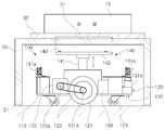
도 3은 본 발명의 바람직한 실시예에 따른 무인 화물 이송로봇의 내부 구성 및 지지판이 파렛트의 지지판삽입부에 삽입되어 지지되는 구성을 나타낸 측면도,
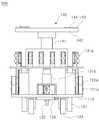
도 4는 본 발명의 바람직한 실시예에 따른 무인 화물 이송로봇의 내부 구성을 나타낸 정면도,
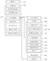
도 5는 본 발명의 바람직한 실시예에 따른 무인 화물 이송로봇의 기능적 구성을 나타낸 블록도,
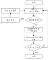
도 6은 본 발명의 바람직한 실시예에 따른 무인 화물 이송시스템의 동작원리를 나타낸 플로우챠트,
도 7은 본 발명의 바람직한 실시예에 따른 무인 화물 이송시스템에 의해 무인 화물 이송로봇이 자율주행하여야 하는 이동경로의 예시가 도시된 개략도,
도 8은 본 발명의 바람직한 실시예에 따른 무인 화물 이송시스템에 의해 무인 화물 이송로봇의 자율주행 제어를 위한 기구학 모델을 나타낸 그래프,
도 9는 본 발명의 바람직한 실시예에 따른 무인 화물 이송로봇의 이동궤적을 나타낸 그래프,
도 10은 본 발명의 바람직한 실시예에 따른 무인 화물 이송로봇의 거리 및 각도오차를 나타낸 그래프,
도 11은 본 발명의 바람직한 실시예에 따른 무인 화물 이송로봇이 목적위치에 도달하여 리프팅위치를 탐색하는 동작원리를 나타낸 개략도,
도 12는 본 발명의 바람직한 실시예에 따른 QR표시부의 구성을 나타낸 개략도,
도 13은 본 발명의 바람직한 실시예에 따른 QR표시부 및 표시제어부의 구성을 나타낸 개략도,
도 14는 본 발명의 바람직한 실시예에 따른 클라이언트단말의 구성을 나타낸 개략도이다.1 is a schematic view showing the configuration of an unmanned cargo transfer system according to a preferred embodiment of the present invention,
Figure 2 is a perspective view showing the external configuration of the unmanned cargo transfer robot according to a preferred embodiment of the present invention,
Figure 3 is a side view showing the internal configuration and the support plate of the unmanned cargo transfer robot according to a preferred embodiment of the present invention is inserted into the support plate insert portion of the pallet is supported;
Figure 4 is a front view showing the internal configuration of the unmanned cargo transfer robot according to a preferred embodiment of the present invention,
Figure 5 is a block diagram showing the functional configuration of the unmanned cargo transfer robot according to a preferred embodiment of the present invention,
Figure 6 is a flow chart showing the operation principle of the unmanned cargo transfer system according to a preferred embodiment of the present invention,
Figure 7 is a schematic diagram showing an example of the movement path that the unmanned cargo transfer robot should autonomously run by the unmanned cargo transfer system according to a preferred embodiment of the present invention,
8 is a graph illustrating a kinematic model for autonomous driving control of an unmanned cargo transport robot by an unmanned cargo transport system according to a preferred embodiment of the present invention;
9 is a graph showing the movement trajectory of the unmanned cargo transfer robot according to a preferred embodiment of the present invention;
10 is a graph showing the distance and angle error of the unmanned cargo transfer robot according to a preferred embodiment of the present invention,
11 is a schematic view showing the operation principle of the unmanned cargo transfer robot according to a preferred embodiment of the present invention to reach the target position to search the lifting position,
12 is a schematic diagram showing the configuration of a QR display unit according to a preferred embodiment of the present invention;
13 is a schematic diagram showing the configuration of a QR display unit and a display control unit according to a preferred embodiment of the present invention;
14 is a schematic diagram showing the configuration of a client terminal according to a preferred embodiment of the present invention.
이하 첨부된 도면을 참조하면서 본 발명에 따른 바람직한 실시예를 상세히 설명하기로 한다. 이에 앞서, 본 명세서 및 청구범위에 사용된 용어나 단어는 통상적이거나 사전적인 의미로 한정해서 해석되어서는 아니 되며, 발명자는 그 자신의 발명을 가장 최선의 방법으로 설명하기 위해 용어의 개념을 적절하게 정의할 수 있다는 원칙에 입각하여, 본 발명의 기술적 사상에 부합하는 의미와 개념으로 해석되어야만 한다.Hereinafter, preferred embodiments of the present invention will be described in detail with reference to the accompanying drawings. Prior to this, terms and words used in the present specification and claims should not be construed as limited to ordinary or dictionary terms, and the inventor should appropriately interpret the concepts of the terms appropriately The present invention should be construed in accordance with the meaning and concept consistent with the technical idea of the present invention.
따라서, 본 명세서에 기재된 실시예와 도면에 도시된 구성은 본 발명의 가장 바람직한 일 실시예에 불과할 뿐이고 본 발명의 기술적 사상을 모두 대변하는 것은 아니므로, 본 출원시점에 있어서 이들을 대체할 수 있는 다양한 균등물과 변형예들이 있을 수 있음을 이해하여야 한다.Therefore, the embodiments described in this specification and the configurations shown in the drawings are merely the most preferred embodiments of the present invention and do not represent all the technical ideas of the present invention. Therefore, It is to be understood that equivalents and modifications are possible.
본 발명의 바람직한 실시예에 따른 무인 화물 이송로봇을 이용한 무인 화물 이송시스템(이하에서는 '무인 화물 이송시스템'이라 명칭함)은, 이동경로상에 배치된 QR랜드마크의 인식을 통해 로봇의 현재위치를 인식 및 연산된 로봇위치를 보정함으로써 설치 및 유지보수 비용을 절감하며, 화물(10)이 파렛트(30) 상에 적재된 밸런싱 상태 또는 지지판(142)에 적재된 파렛트(30)의 밸런싱 상태를 체크하여 밸런싱 상태를 조정하거나 외부로 경고하여 적재된 화물(10)이 전복되는 안전사고를 미연에 방지할 수 있는 시스템으로서, 도 1에 도시된 바와 같이, 무인 화물 이송로봇(100) 및 호스트단말(200)을 포함하여 구비된다.Unmanned cargo transfer system (hereinafter referred to as 'unmanned cargo transfer system') using an unmanned cargo transfer robot according to a preferred embodiment of the present invention, the current position of the robot through the recognition of the QR landmark placed on the movement path Reduction of installation and maintenance costs by correcting the robot position and the calculated robot position, the balancing state of the
먼저, 상기 무인 화물 이송로봇(이하에서는 '이송로봇(100)'이라 명칭함)은, 무선통신망을 통해 조작신호를 수신하여 수신된 조작신호에 따라 이송로봇(100)의 작업계획을 수립하되, 도 2 내지 도 4에 도시된 바와 같이 이동경로상에 배치된 복수 개의 QR랜드마크의 이미지를 촬영하는 QR카메라(132)가 구비되어 상기 QR카메라(132)에서 입력된 QR랜드마크 이미지에 대한 영상정보를 이미지 프로세싱하여 상기 QR랜드마크에 포함된 위치 정보를 판독하며, 판독된 위치 정보를 기초로 하여 이송로봇의 현재위치 데이터를 보정하여 이송로봇의 작업계획을 수립한다.First, the unmanned cargo transfer robot (hereinafter referred to as 'transport robot 100'), receiving the operation signal through a wireless communication network to establish a work plan of the
상기 호스트단말(200)은, 상기 무선통신망을 통해 상기 이송로봇(100)으로 조작신호를 전송하여 사용자의 화물 운송지시를 전달하는 단말장치로서, 통상의 PC를 이용할 수 있다.The
여기서, 상기 호스트단말(200)에는 이송로봇(100) 또는 테이블 압력센서(21)에 의해 생성된 경고표시를 외부로 표시할 수 있도록 모니터 등의 디스플레이, 스피커 및 램프 등의 표시수단이 구비되어, 경고메세지, 경고점등 및 경고음의 형태로 경고표시를 수행할 수 있다. 이와 같이 호스트단말(200)을 통해 외부로 표시되는 경고표시에 의해 관리자가 경고내용을 즉각적으로 인지할 수 있게 된다.Here, the
또한, 상기 이송로봇(100)은 상기 QR카메라(132)에서 입력된 QR랜드마크 이미지에 대한 영상정보를 이미지 프로세싱하여 상기 QR랜드마크에 포함된 다음 QR랜드마크의 위치정보를 기초로 하여 이송로봇(100)의 작업계획을 보정할 수 있다.In addition, the
더불어, 설정된 이동경로 또는 장애물을 회피하기 위해 새로 탐색된 이동경로를 따라 이동 중에 상기 QR카메라(132)를 통해 QR랜드마크가 인식되면, 해당 QR랜드마크에 포함된 위치정보를 판독하여 현재위치를 보정하여 작업계획을 수립하되, 해당 QR랜드마크의 외부모서리를 인식하여 무인 화물 이송로봇(100)의 방향오차(각도오차,θe)가 허용오차보다 커질 경우 현위치에서 이동을 멈추어 이동경로를 이탈하지 않도록 진행방향에 대한 확인과 보정을 수행한다.In addition, if a QR landmark is recognized through the
더불어, 상기 이송로봇(100)은, 화물(10) 또는 파렛트(30)의 하부를 지지하는 지지판(142)을 승강시켜 화물(10)을 리프팅하는 자율 리프팅 기능이 구비되되, 도 2 및 도 4에 도시된 바와 같이 상기 지지판(142)의 상부면에 일정간격으로 이격 배치되어 리프팅 구동에 따라 상기 지지판(142)이 화물(10) 또는 파렛트(30)의 하부면을 지지하면서 가해지는 압력을 감지하는 복수 개의 압력감지센서(143)가 구비되고, 각 압력감지센서(143)의 센서 감지결과에 따라 파렛트(30)를 리프팅하는 밸런싱 상태를 연산하여 밸런싱 상태가 임계치 이하일 경우 외부로 표시하기 위한 경고신호를 생성하여 상기 무선통신망을 통해 호스트단말(200)로 전송하며, 상기 경고신호를 수신한 호스트단말(200)은 상기 디스플레이, 스피커 및 램프 등을 통해 외부로 경고내용을 표시하도록 동작한다.In addition, the
그리고, 상기 이송로봇(100)의 지지판(142)에는 파렛트(30) 상에 적재된 화물(10)의 중량을 감지하는 중량감지센서(145)가 구비되고, 상기 중량감지센서(145)의 센서 감지결과에 따라 화물(10)의 중량이 임계치를 초과할 경우 외부로 경고표시하기 위한 경고신호를 생성하여 무선통신망을 통해 호스트단말(200)로 전송하며, 상기 경고신호를 수신한 호스트단말(200)은, 상기의 경고수단을 통해 외부로 경고내용을 표시하도록 동작한다.In addition, the
한편, 도 3에 도시된 바와 같이 본 발명의 바람직한 실시예에 따른 무인 화물 이송시스템은 화물(10)이 적재된 테이블(20)에 구비된 복수 개의 지지다리에 각각 배치되어 상기 테이블(20) 상에 적재된 화물(10)이 하중에 의해 가해지는 압력을 각각 감지하는 테이블 압력센서(21)를 더 포함하여 구비되며, 상기 호스트단말(200)은 각 테이블 압력센서(21)의 센서 감지결과에 따라 테이블(20)에 화물(10)이 적재된 밸런싱 상태를 연산하여 밸런싱 상태가 임계치 이하일 경우, 상기 경고수단을 통해 외부로 경고내용을 표시하도록 동작한다.Meanwhile, as shown in FIG. 3, the unmanned cargo transfer system according to the preferred embodiment of the present invention is disposed on a plurality of support legs provided on the table 20 on which the
여기서, 상기 테이블 압력센서(21)의 센서 감지결과가 호스트단말(200)로 전송됨에 있어서, 각 테이블 압력센서(21)과 호스트단말(200) 사이에는 무선통신 수단이 구비되어 상호간의 신호연결을 통해 감지결과가 송수신될 수도 있으며, 상기 호스트단말(200)은 테이블 압력센서(21)에 근접된 이송로봇(100)을 통해 테이블 압력센서(21)의 센서 감지결과를 무선통신망을 통해 전달받도록 구비될 수도 있다.Here, in the sensor detection result of the
또한, 호스트단말(200)은 경고신호를 전송한 이송로봇(100)의 분류코드 및 우치정보 또는 해당 화물(10)의 분류코드 및 위치정보를 화면상에 디스플레이하도록 구비될 수 있다.In addition, the
이를 위해 본 발명의 바람직한 실시예에 따른 무인 화물 이송시스템에서는, 복수 대의 이송로봇(100)을 구분하기 위한 분류코드를 각 이송로봇(100)별로 부여하며, 이송로봇(100)은 호스트단말(200)로 경고신호를 전송할 때 해당 분류코드를 포함시켜 전송함으로써 호스트단말(200)이 해당 이송로봇(100)의 분류코드를 식별할 수 있다.To this end, in the unmanned cargo transfer system according to a preferred embodiment of the present invention, a classification code for distinguishing a plurality of
또한, 이송로봇(100)은 수립된 작업계획 또는 QR랜드마크의 판독을 통해 보정된 현재위치 데이터로 현재 위치한 위치정보를 판단할 수 있으며, 상기 경고신호를 호스트단말(200)로 전송할 때 현재 위치정보를 함께 전송함으로써 호스트단말(200)이 해당 이송로봇(100)의 현재 위치정보를 식별할 수 있다.In addition, the
마찬가지 원리로, 복수 개의 테이블(20) 또는 화물(10)에는 각각을 구분하기 위한 분류코드가 부여되며, 이송로봇(100) 또는 테이블 압력센서(21)는 호스트단말(200)로 경고신호를 전송할 때 해당 분류코드를 포함시켜 전송함으로써 호스트단말(200)이 해당 화물 또는 테이블(20)의 분류코드 및 현재 위치정보를 식별할 수 있다. 더불어, 상기 호스트단말(200)에는 작업장 내의 맵데이터가 저장됨으로써 상술한 바와 같이 식별된 각 이송로봇(100), 화물(10) 및 테이블(20)의 위치정보를 기초로 하여 저장된 맵데이터 내에서 각 이송로봇(100), 화물(10) 및 테이블(20)의 위치정보를 화면상에 표시하도록 구비될 수 있다.In the same principle, a plurality of tables 20 or
본 발명의 바람직한 실시예에 따른 무인 화물 이송시스템에서는, 작업자가 이동하면서 각 이송로봇(100), 화물(10) 및 테이블(20)의 위치정보를 실시간으로 확인할 수 있도록, 도 14에 도시된 바와 같이 각 이송로봇(100), 화물(10) 및 테이블(20)의 현재 위치를 화면 상에 표시하는 클라이언트단말(400)을 더 포함하여 구비될 수 있다.In the unmanned cargo transfer system according to a preferred embodiment of the present invention, as shown in Figure 14 so that the worker can check the location information of each
보다 구체적으로 설명하면, 상기 클라이언트단말(400)에는 작업장 내의 맵데이터가 저장되며, 도면에서와 같이 상기 호스트단말(200)로부터 각 이송로봇(100), 화물(10) 및 테이블(20)의 현재 위치정보를 수신함으로써 저장됨 맵데이터 내에서 수신된 위치정보를 기초로 하여 각 이송로봇(100), 화물(10) 및 테이블(20)의 현재 위치를 화면 상에 표시할 수 있다.More specifically, the
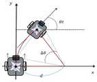
한편, 본 발명의 바람직한 실시예에 따른 무인 화물 이송시스템에 의한 이송로봇(100)의 자율주행 제어를 위한 기구학 모델은 도 8에 도시된 바와 같다. 도 8을 참고하면 이송로봇(100)의 중심점은 (xc,yc) 좌표이고, υ는 로봇 중심의 선속도, Vr과 Vl은 양측에 구비된 각 구동바퀴(121)의 선속도이다. 또한, θ는 이송로봇(100)의 앞부분이 향하는 방향각이다.On the other hand, the kinematic model for the autonomous driving control of the
간단한 기구학 모델을 얻기 위해 바퀴구동부(120)의 구동바퀴(121)는 미끄러짐이 없다고 가정하면, 하기의 [수학식 1]과 [수학식 2]와 같은 기구학 방정식을 얻을 수 있다. 또한, ω는 반시계 방향에 대한 이송로봇(100)의 각속도를 나타내며, ωr, ωl은 각 구동바퀴(121)의 각속도, l1은 양 구동바퀴(121)의 윤거, r은 구동바퀴(121)의 반지름을 각각 나타낸다.In order to obtain a simple kinematic model, assuming that the
따라서, 상기 호스트단말(200)은, 하기의 [수학식 1]에 의해 산출된 로봇 중심의 선속도(υ)와, 하기의 [수학식 2]에 의해 산출된 반시계 방향에 대한 로봇의 각속도(ω)를 이용하여 이송로봇의 작업계획이 수립되도록 하기 위한 조작신호를 을 전송하게 된다.Therefore, the
[수학식 1][Equation 1]

[수학식 2]&Quot; (2) "

또한, 도 9에는 본 발명의 바람직한 실시예에 따른 이송로봇(100)의 이동 궤적에 대한 그래프가 도시되어 있다. 도 9를 참고하면 하기의 [수학식 3]과 [수학식 4]를 획득할 수 있다.In addition, Figure 9 is a graph for the movement trajectory of the
[수학식 3]&Quot; (3) "

[수학식 4]&Quot; (4) "

(여기서, d는 이송로봇(100)의 이동한 궤적의 중심축과의 거리, △VL은 임의의 시간 △t 동안 좌측 구동바퀴(121)가 이동한 거리, △VR은 임의의 시간 동안 우측 구동바퀴(121)가 이동한 거리, △θ는 임의의 시간 동안 이송로봇(100)이 이동한 궤적의 중심축과의 각도를 각각 의미함.)(Where d is the distance from the center axis of the trajectory of the
따라서, 임의의 시간 △t 동안에 양 구동바퀴(121)의 이동거리를 통해 이송로봇(100)이 이동한 궤적의 중심축과의 거리 d는 상기 [수학식 4]로부터 하기의 [수학식 5]와 같은 수식을 도출해 낼 수 있다.Therefore, the distance d with respect to the central axis of the trajectory in which the
[수학식 5]&Quot; (5) "

또한, 임의의 시간 △t 동안 이송로봇(100)이 이동한 궤적의 중심축과의 각도(△θ)와 중심의 이동거리 △l은 하기의 [수학식 6]과 [수학식 7]을 획득할 수 있다.In addition, the angle (△ θ) and the moving distance △ l of the center of the trajectory in which the
[수학식 6]&Quot; (6) "

[수학식 7][Equation 7]

한편, 이송로봇(100)의 자율 주행을 위해서는 목표지점까지 이동경로를 이탈하지 않고 경로추정을 수행하여야 한다. 따라서, 실제 작업장 내에서의 이송로봇(100)도 마찬가지로 현재위치 파악과 위치보정을 고려해야 한다. 일반적인 방법으로 모터의 엔코더를 이용한 방식이 많이 이용되고 있으나, 이는 구동바퀴의 미끄러짐 현상에 의한 오차 누적이 발생하여 한계성을 지닌다.On the other hand, for autonomous driving of the
또한, 이송로봇(100)이 자율주행 중에 노면의 상태, 주변 환경에 따른 진행방향을 미치지 않지만 시간이 지날수록 누적현상으로 인하여 크게는 진행경로를 이탈하게 될 수도 있고, 도 10에 도시된 바와 같이 목표점(xd,yd)과 현재 위치(xr,yr)와의 거리 및 각도 오차를 측정하여 이를 바탕으로 양 구동바퀴(121)의 속도를 제어하여 목표점에서 이송로봇(100)까지의 거리오차는 de, 각도오차는 (θe)로 나타내면, 하기의 [수학식 8] 및 [수학식 9)와 같이 표현될 수 있다.In addition, although the
[수학식 8][Equation 8]

[수학식 9]&Quot; (9) "

(여기서, dx와 dy는 x좌표와 y좌표에서 원하는 위치와 로봇(100)과의 거리차이고, θd는 목표점과 이송로봇(100)을 잇는 선각도이고, θr은 이송로봇(100)의 현재 방향각을 의미한다.(Where, dx and dy are the distance between the desired position and the
한편, 본 발명의 바람직한 실시예에 따른 이송로봇(100)은, 도 2 내지 도 4에 도시된 바와 같이, 본체부(110), 바퀴구동부(120), 센서부(130), 리프팅부(140), 무선통신부(150), 주제어부(160), 모션제어부(170) 및 배터리(180)를 포함하여 구비된다.On the other hand, the
먼저, 상기 본체부(110)는, 이송로봇(100)의 다른 구성이 배치 또는 탑재되는 베이스프레임으로서, 배치 또는 탑재된 다른 구성들을 외부로부터 커버하기 위한 케이싱(111)이 장착되며, 지면과 파렛트(30)가 적재된 테이블(20)의 상부 프레임 사이의 공간에 이동배치될 수 있는 전고를 갖도록 구비된다. 여기서, 도면에서는 본체부(110)의 외형이 사각의 박스형상인 것을 예시하였으나 이에 국한되지 않으며 원형, 타원형, 삼각형 및 오각형 등 다양한 형상으로 형성될 수 있다.First, the
상기 바퀴구동부(120)는, 상기 본체부(110)의 하부에 배치되어 본체부(110)를 이동시키는 구동바퀴(121)와, 상기 구동바퀴(121)를 회전시키는 구동모터(122)를 포함하여 구비된다.The
여기서, 상기 바퀴구동부(120)는, 본체부(110)가 평면상에서 병진운동과 회전운동이 가능한 3자유도 구성으로 설계되며, 구동모터(122)의 방향전환이 없는 전후 구동만으로 본체부(110)의 3자유도 운동이 구현되는 옴니휠 또는 메카넘휠 구조로 구비될 수도 있다.Here, the
또한, 상기 구동바퀴(121)는 본체부(110)의 중앙부 양측에 두 개가 배치될 수 있으며, 전단과 후단에는 구동력없이 구동바퀴(121)의 회전에 의해 함께 회전하는 보조바퀴(124)가 구비되어 안정적으로 본체부(110)를 지지할 수 있다. 이때, 상기 보조바퀴(124)는 외력에 의해 방향전환이 자유로운 캐스터 바퀴가 이용되는 것이 바람직하다.In addition, two driving
더불어, 구동바퀴(121)의 바퀴축(121a)과 구동모터(122)의 모터축(122a)은 구동벨트(123)에 의해 동력전달되도록 연결되어 상기 구동모터(122)의 회전력이 구동바퀴(121)로 전달되도록 구비되며, 상기 구동모터(122)는 모션제어부(170)의 제어신호에 따라 구동바퀴(121)를 구동하게 된다.In addition, the
상기 센서부(130)는, 본체부(110)에 탑재되고 외부의 장애물 또는 다른 이송로봇(100)을 감지하는 장애물감지센서(131)와, 이동경로상에 배치된 QR랜드마크의 이미지를 촬영하는 QR카메라(132)를 포함하여 구비된다.The
여기서, 상기 장애물감지센서(131)는, 본체부(110)의 전방 및 후방에 배치되어 단거리에 위치한 장애물 또는 파렛트(30)가 적재된 테이블(20)을 인식하는 초음파센서(131a)와, 본체부(110)의 전방에 배치되어 장거리에 위치한 장애물을 인식하는 LRF센서(131b)를 포함하여 구비된다.Here, the
상기 단거리는 이송로봇(100)이 전진, 후진, 회전 등과 같이 움직일 경우 주변의 장애물과 접촉할 수 있는 근접거리를 의미하며, 상기 장거리는 이송로봇(100)의 이동경로 상에 배치된 장애물을 인식하여 해당 장애물을 회피하여 이동경로를 수정할 수 있도록 일정거리 이격된 거리를 의미한다.The short distance means a close distance that may be in contact with an obstacle around when the
또한, 상기 QR랜드마크는 도 7에 도시된 바와 같이 이동경로 상에 배치되되 이송로봇(100)이 이동하며 위치를 보정하여야 위치(노드)마다 배치된 QR코드 이미지로서, 해당 QR랜드마크가 배치된 위치의 위치정보를 포함하여, 이동경로 상의 다음 QR랜드마크의 위치정보를 포함하도록 이미지가 조합되어 형성될 수 있며, 도면에서와 같이 이동경로상의 바닥면에 배치될 수도 있고 벽면이나 주변 물체의 하부 위치에 수직하게 배치될 수도 있다. 따라서, 상기 QR카메라(132)는 QR랜드마크가 바닥면에 배치된 경우 본체부(110)의 하부에 배치되어 하향 촬영하도록 배치되며, QR랜드마크가 측방에 배치된 경우 본체부(110)의 전방에 배치되어 전방을 향해 촬영하도록 배치되는 것이 바람직하다.In addition, the QR landmark is placed on the movement path as shown in Figure 7, but the
이와 같이, 오염과 손상에 강하며 훼손시 높은 복원율의 특성을 가지며, 이미지에 포함된 위치찾기 심벌을 이용하여 배경모양의 영향을 받지 않고 360도 어느 각도에서도 고속으로 인식이 가능한 QR코드 이미지로 이루어진 QR랜드마크를 위치인식의 부수적인 수단으로 이용함으로써, 설치 및 유지보수 비용을 절감할 수 있다. 또한, 상기 QR랜드마크에 현위치정보를 입력함으로써 이송로봇(100)의 현재위치 인식 및 위치보정이 용이해질 뿐만 아니라, 상기 QR랜드마크에 이동경로상의 다음 QR랜드마크의 위치정보 등과 같이 이송로봇(100)의 자율주행에 필요한 데이터를 대량으로 입력할 수 있으므로 보다 정밀한 자율주행 제어가 가능한 효과를 구현할 수 있다.As such, it is resistant to contamination and damage, and has a high recovery rate when damaged, and consists of a QR code image that can be recognized at high speed at any angle of 360 degrees without being affected by the background shape by using a location symbol included in the image. By using QR landmarks as an additional means of location recognition, installation and maintenance costs can be reduced. In addition, by inputting the current position information into the QR landmark, not only the current position recognition and position correction of the
따라서, 상기 주제어부(160)는 QR카메라(132)에서 입력받은 영상정보의 이미지 프로세싱 결과에 따라 이송로봇(100)의 작업계획을 수립하되, 상기 QR랜드마크에 포함된 위치 정보를 기초로 하여 이송로봇(100)의 현재위치를 보정하여 이송로봇(100)의 작업계획을 수립하며, 더불어, 상기 QR랜드마크에 포함된 이동경로상의 다음 QR랜드마크의 위치정보를 기초로 하여 이송로봇(100)의 작업계획을 수립할 수 있는 것이다.Therefore, the
그리고, QR랜드마크에 포함된 위치정보를 판독하여 현재위치를 보정하여 작업계획을 수립하되, 해당 QR랜드마크의 외부모서리(위치찾기심벌 또는 외곽테두리)를 인식하여 무인 화물 이송로봇(100)의 방향오차(각도오차,θe)가 허용오차보다 커질 경우 현위치에서 이동을 멈추어 이동경로를 이탈하지 않도록 진행방향에 대한 확인과 보정을 수행할 수 있다.And, by reading the location information contained in the QR landmark to correct the current position to establish a work plan, the external edge of the QR landmark (locating symbol or the outer border) by recognizing the unmanned
또한, 상기 센서부(130)에는 본체부(110)의 전방에 배치되어 전방이미지를 촬영하는 전방카메라(133)를 포함하여 구비될 수 있다. 상기 전방이미지는 로봇(100)의 이동경로 상에 배치된 장애물을 회피하는데 이용되기 위한 이미지로서, 상기 주제어부(160)는 상부카메라(134)에서 입력받은 영상정보의 이미지 프로세싱 결과에 따라 이송로봇(100)의 작업계획을 수립하며, 상기 모션제어부(170)는 상기 주제어부(160)의 작업계획에 따라 전방카메라(133)의 영상정보를 기초로 하여 상기 전방에 감지된 장애물을 회피하여 주행할 수 있는 제어신호를 생성한다.In addition, the
상기 리프팅부(140)는, 본체부(110)의 상부에 배치되되 상하로 리프팅 구동하는 리프트구동부(141)와, 상기 리프트구동부(141)의 상단에 장착되어 화물(10)이 적재된 파렛트(30)의 하부면을 지지하는 지지판(142)을 포함하여 구비된다.The
여기서, 상기 리프트구동부(141)는 통상의 유압 또는 공압의 액츄에이터를 이용할 수 있고, 구동모터와 기어와의 조합된 구성으로 이루어진 동력전달 구조, 상하로 움직이는 X자형 승강프레임으로 구성될 수도 있으며, 이에 한정되지 않으며 제어신호에 의해 화물(10)을 승강할 수 있는 다양한 구성이 적용 가능하다. 한편, 상기 리프트구동부(141)는 모션제어부(170)의 제어신호에 따라 지지판(142)을 위아래로 승강하게 구동한다.Here, the
또한, 상기 지지판(142)은, 도 3에 도시된 바와 같이 파렛트(30)의 하부면에 형성된 지지판삽입부(31)와 매칭되어 치합되는 형상으로 형성되어 상기 지지판삽입부(31)에 삽입되면서 파렛트(30)의 하부면을 리프팅하도록 구비될 수 있다.In addition, the
여기서, 상기 지지판삽입부(31)이 파렛트(30) 상에 적재되는 화물(10)의 무게를 감안하여 무게중심에 해당하는 위치에 형성된 경우, 상기 지지판(142)을 지지판삽입부(31)에 삽입하는 것만으로도 무게중심에 부합되는 위치를 지지할 수 있게되므로 지지판(142)에 적재되는 화물(10)의 밸런싱 상태를 양호하게 유지할 수 있다.Here, when the support
이때, 도면에는 상기 파렛트(30)의 하부에 형성된 지지판삽입부(31)이 파렛트(30)의 하부면 상에서 오목하게 내입된 홈형상인 것을 예시하였으나 이에 국한되지 않으며, 내입되지 않고 상기 지지판삽입부(31)의 테두리부분이 하부방향으로 돌출되게 융기된 형태로 형성될 수도 있다. 또한, 상기 지지판(142)은 도 2에 도시된 바와 같이 4개의 돌출부를 갖는 십자형의 판 형상으로 형성될 수 있다.In this case, although the support
상기 무선통신부(150)는, 본체부(110)에 탑재되고 호스트단말(200)과 무선통신망으로 신호연결되어 도 5에 도시된 바와 같이 상기 호스트단말(200)의 조작신호를 수신하고, 상기 센서부(130)의 다양한 감지결과를 송신한다.The
여기서, 복수 대의 이송로봇(100)은 상호간의 무선통신부(150)를 이용하여 상기 호스트단말(200)의 조작신호를 해당 이송로봇(100)으로 대신하여 전달할 수도 있다. 상기 주제어부(160)는 본체부(110)에 탑재되고 상기 무선통신부(150)를 통해 수신한 호스트단말(200)의 조작신호와, 상기 장애물감지센서(131)의 센서 감지결과 및, 상기 QR카메라(132)에서 입력받은 영상정보의 이미지 프로세싱 결과에 따라 이송로봇(100)의 작업계획을 수립한다. 여기서, 상기 주제어부(160)를 Linux 기반의 임베디드 보드로 사용하여 작업계획과 영상처리 및 LRF센서(131b)의 데이터처리를 수행하도록 구성하였으나 이에 한정되지 않는다.Here, the plurality of
상기 모션제어부(170)는, 주제어부(160)의 작업계획에 따라 모터 제어, 리프팅 제어 및 밸런스 제어를 수행하면서 이송로봇(100)의 움직임을 제어하는 제어신호를 생성한다. 여기서, 상기 모션제어부(170)를 ARM사의 Cortex-M3 기반의 프로세서를 사용하여 실시간 모터제어와 각 센서값들을 처리하며, 호스트단말(200)의 어플리케이션과 실시간으로 통신하여 상태모니터링, 간단한 비상정지기능 및 명령전송이 가능하도록 구성하였으나 이에 한정되지 않는다. 또한, 상기 모션제어부(170)는 센서인터페이스를 구비하여 각 센서에서 감지한 결과를 주제어부(160)로 송신한다.The
상기 배터리(180)는 본체부(110)에 탑재되고 이송로봇(100) 제어와 움직임 등에 필요한 전원을 공급한다.The
한편, 본 발명의 바람직한 실시예에 따른 이송로봇(100)은, 화물(10) 또는 파렛트(30)의 적재된 밸런싱 상태를 감지하여 리프팅부(140)의 지지위치를 밸런싱 상태가 양호한 정위치로 조정하거나 외부로 경고 표시하여 관리자로 하여금 조치받도록 알릴 수 있는데, 이를 위해 도 2 내지 도 4에 도시된 바와 같이 상기 센서부(130)는 지지판(142)의 각 돌출부의 상부면에 배치되어 상기 리프팅부(140)의 리프팅 구동에 따라 상기 지지판(142)이 화물(10) 또는 파렛트(30)의 하부면을 지지하면서 가해지는 압력을 감지하는 복수 개의 압력감지센서(143)를 포함하여 구비된다. 즉, 상기 파렛트(30)를 리프팅함에 있어서 이송로봇(100)의 위치를 조절하여 리프팅부(140)에 의해 지지되는 방향과 중심에 따른 파렛트(30)의 리프트 위치를 변경할 수 있다. 이와 같이 리프팅부(140)를 통해 들어 올리는 리프팅 위치에 따라 이송로봇(100)의 움직이는데 필요한 변위가 변화되는데, 이러한 변위의 변화를 고려하여 이송운용계획을 수립할 수 있다.On the other hand, the
또한, 상기 주제어부(160)는 각 압력감지센서(143)의 센서 감지결과에 따라 상기 파렛트(30)를 리프팅하는 밸런싱 상태를 연산하여 이송로봇(100)의 작업계획을 수립하며, 상기 모션제어부(170)는 주제어부(160)의 작업계획에 따라 밸런싱 상태가 임계치 이하일 경우 지지판(142)이 파렛트(30)의 하부면을 지지하는 위치를 조정하거나 외부로 경고표시하도록 제어하는 제어신호를 생성할 수 있다.In addition, the
여기서, 상기 지지판(142)이 파렛트(30)의 하부면을 지지하는 위치를 조정할 수 있도록, 도 2 및 도 4에 도시된 바와 같이 리프팅부(140)는 지지판(142)의 상부에 배치되어 상부면에 안착된 파렛트(30)의 위치가 조정되도록 구동하는 레일부(144)를 더 포함하여 구비되며, 상기 모션제어부(170)는 연산된 밸런싱 상태가 임계치 이하일 경우 상기 압력감지센서(143)의 센서 감지결과를 기초로 하여 파렛트(30)가 정위치로 이동하도록 레일부(144)의 구동을 제어하는 제어신호를 생성한다.Here, as illustrated in FIGS. 2 and 4, the
이와 같이 화물(10) 또는 파렛트(30)의 밸런싱 상태를 연산하여 리프팅부(140)의 지지위치를 밸런싱 상태가 양호한 정위치로 조정하거나 외부로 경고표시하여 관리자로 하여금 조치받도록 알림함으로써 적재된 화물(10)이 리프팅하는 과정 또는 리프팅되어 이송되는 과정에 전복되는 안전사고를 미연에 방지할 수 있다.As such, by calculating the balancing state of the
또한, 상기 레일부(144)를 구동제어하여 파렛트(30)를 정위치로 이동시킬 수 있으므로 밸런싱 상태가 양호하지 않게 적재되된 상태에서도 안정적으로 화물(10)을 이송할 수 있다.In addition, since the
한편, 본 발명의 바람직한 실시예에 따른 센서부(130)는, 본체부(110)에 배치되어 지지판(142)의 이미지 및 지지판삽입부(31)의 이미지를 촬영하는 상부카메라(134)를 더 포함하고, 상기 주제어부(160)는 상부카메라(134)에서 입력받은 영상정보의 이미지 프로세싱 결과에 따라 이송로봇(100)의 작업계획을 수립하며, 상기 모션제어부(170)는 주제어부(160)의 작업계획에 따라 상부카메라(134)의 영상정보를 기초로 하여 지지판(142)이 승강하면서 지지판삽입부(31)에 정합되어 삽입되도록 이송로봇(100)의 움직임을 제어하는 제어신호를 생성할 수 있다. 이와 같이 지지판(142)의 이미지 및 지지판삽입부(31)의 이미지를 촬영하는 상부카메라(134)에서 촬영된 영상정보를 이미지 프로세싱함으로써 이송로봇(100)의 위치를 조정하여 지지판(142)이 상승하면서 지지판삽입부(31)에 정합되도록 삽입할 수 있는 것이다.On the other hand, the
또한, 상기 주제어부(160)는, 호스트단말(200)의 조작신호를 통해, 하기의 [수학식 1]에 의해 산출된 로봇 중심의 선속도(υ)와, 상기의 [수학식 2]에 의해 산출된 반시계 방향에 대한 로봇의 각속도(ω)를 이용하여, 이송로봇의 작업계획을 수립할 수 있는 것이다.In addition, the
한편, 도 12 및 도 13에 도시된 바와 같이 본 발명의 바람직한 실시예에 따른 무인 화물 이송시스템은 이동경로 상에 배치되어 상기 QR랜드마크를 화면출력하는 표시하는 복수 개의 QR표시부(300) 및, 각 QR표시부(300)의 화면구동을 제어하는 표시제어부(310)를 더 포함하는 것이 바람직하다.On the other hand, as shown in Figure 12 and 13 unmanned cargo transfer system according to a preferred embodiment of the present invention is disposed on the movement path a plurality of
보다 구체적으로 설명하면, 이동경로상의 각 노드에는 이송로봇(100)의 위치보정을 위한 QR랜드마크가 배치되는데, 이러한 QR랜드마크는 해당 위치에 인쇄되어 부착된 형태로 배치될 수도 있으나 외부의 영향에 의한 오염 및 훼손이 가해지기 쉽다. 따라서, 이러한 QR랜드마크를 각 노드별로 배치하되 해당 QR랜드마크를 화면상에 표시하여 출력하는 QR표시부(300)를 통해 해당 QR랜드마크를 각 노드에 배치할 수 있다.In more detail, QR nodes for position correction of the
여기서, 각 QR표시부(300)는 LCD, LED, OLED 등과 같은 디스플레이 화면의 형태로 구비되며, 상기 표시제어부(310)와는 각각 유,무선 통신라인으로 신호연결되어 상기 표시제어부(310)의 제어에 의해 각각 개별적인 QR랜드마크를 화면출력할 수 있다. 또한, 도 13과 같이 상기 표시제어부(310)는 호스트단말(200)의 제어신호에 따라 각 QR표시부(300)의 화면구동을 제어하도록 구비될 수 있다.Here, each of the
따라서, 상기 호스트단말(200)을 이용하여 표시제어부(310)를 통해 각 QR표시부(300) 별로 화면출력되는 QR랜드마크를 목적에 따라 변경하여 출력함으로써 이송로봇(100)의 작업계획을 수정하거나 포함된 위치정보를 수정하고자 할 때마다 각 노드별로 부착되는 QR랜드마크를 일일이 교체할 필요없이 용이하게 QR랜드마크를 변경할 수 있는 효과를 구현한다.
Therefore, by modifying and outputting the QR landmark displayed on the screen for each
다음으로는, 도 6을 참고하여 본 발명의 바람직한 실시예에 따른 무인 화물 이송시스템의 동작원리를 설명하기로 한다.Next, with reference to Figure 6 will be described the operation principle of the unmanned cargo transfer system according to a preferred embodiment of the present invention.
이송로봇(100)이 자율주행하여야 하는 이동경로가 도 7에 도시된 바와 같이 출발위치(△)에서 출발하여 4개의 QR랜드마크를 거쳐 화물(10)이 적재된 파렛트(30)의 위치(○)를 경유하여 파렛트(30)를 리프팅하고 다시 최종목적지인 출발위치(△)로 복귀하는 경로일 때, 먼저, 사용자가 호스트단말(200)을 통해 화물 운송지시를 입력하면 호스트단말(200)에서 무선통신을 이용하여 이송로봇(100)으로 화물운송을 지시하는 조작신호를 전송한다.As shown in FIG. 7, the movement route that the
이어서, 무선통신부(150)를 통해 상기 호스트단말(200)로부터 조작신호를 전송받은 이송로봇(100)은 주제어부(160)가 수신된 조작신호에 따른 이송로봇(100)의 작업계획을 수립하며, 모션제어부(170)는 상기 주제어부(160)의 작업계획에 따라 이송로봇(100)의 움직임을 제어하는 제어신호를 생성하여 바퀴구동부(120) 및 센서부(130)로 전송함으로써 이송로봇(100)이 출발위치(△)에서 첫번째 QR랜드마크을 향해 이동하게 된다. 이때, 이동하면서 센서부(130)에 구비된 장애물감지센서(131), QR카메라(132) 및 전방카메라(133)가 동작하여 주변 영상 및 바닥면의 영상을 촬영하며 영상정보를 획득하고 주변장애물을 감지한 센서값을 획득하게 된다.Subsequently, the
이후, 무인 화물 이송로봇(100)이 이동을 지속하다 어떠한 장애물도 감지되지 않으면 첫번째 QR랜드마크까지 이동하게 되고, 이동경로 상에 임의의 장애물이 감지된 경우, 상기 주제어부(160)는 이송로봇(100)의 이동을 일시적으로 정지하여 일정시간 동안 대기하도록 제어한다. 이후, 해당 장애물이 경로상에서 사라질 경우 이동을 재개하되 해당 장애물이 지속적으로 존재하는 경우 다른 경로를 탐색하여 탐색된 경로로 이송로봇(100)이 이동하도록 제어한다.Then, if the unmanned
이어서, 이동을 지속하다 QR카메라(132)에서 획득된 영상정보에서 첫번째 QR랜드마크가 인식된 경우, 주제어부(160)는 첫번째 QR랜드마크에 포함된 위치 정보를 기초로 하여 이송로봇(100)의 현재위치를 보정하여 이송로봇(100)의 작업계획을 수립하며, 상기 QR랜드마크에 이동경로상의 두번째 QR랜드마크의 위치정보가 포함된 경우 이를 반영하여 작업계획을 수립한다.Subsequently, when the first QR landmark is recognized from the image information acquired by the
또한, 설정된 이동경로 또는 새로 탐색된 이동경로를 따라 이동중에 상기 QR카메라(132)를 통해 QR랜드마크가 인식되면, 해당 QR랜드마크에 포함된 위치정보를 판독하여 현재위치를 보정하여 작업계획을 수립하되, 해당 QR랜드마크의 외부모서리를 인식하여 무인 화물 이송로봇(100)의 방향오차(θe)가 허용오차보다 커질 경우 현위치에서 이동을 멈추어 이동경로를 이탈하지 않도록 진행방향에 대한 확인과 보정을 수행한다.In addition, when a QR landmark is recognized through the
이와 같은 장애물 감지 및 QR랜드마크 인식, 위치보정 절차를 반복하여 네번째 QR랜드마크를 통과한 이송로봇(100)은, 네번째 QR랜드마크에 포함된 위치 정보 및 파렛트(30)의 위치정보를 기초로 하여 작업계획을 수립하여 모션제어부(170)에 의해 이송로봇(100)이 파렛트(30)가 배치된 위치(○)를 향해 이동되도록 제어된다.The
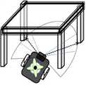
이후, 파렛트(30)가 배치된 위치에 도달하여 센서부(130)의 각 카메라 및 센서들에 의해 파렛트(30) 또는 파렛트(30)가 적재된 테이블(20)을 인식하게 되면, 도 11에 도시된 바와 같이 이송로봇(100)은 테이블(20)에 구비된 4개의 다리가 배치된 위치를 인식하여 테이블(20)상에 적재된 파렛트(30)를 지지하기 위한 적절한 위치를 탐색하게 된다.Thereafter, when the
이때, 센서부(130)에 구비된 상부카메라(134)에서 촬영된 지지판(142)의 이미지 및 파렛트(30)의 하부에 형성된 지지판삽입부(31)의 이미지에 대한 영상정보를 주제어부(160)가 이미지 프로세싱하여 작업계획을 수립하며, 모션제어부(170)는 리프트구동부(141)를 구동제어함과 동시에, 주제어부(160)의 작업계획에 따라 상부카메라(134)의 영상정보를 기초로 하여 지지판(142)이 승강하면서 지지판삽입부(31)에 정합되어 삽입되도록 바퀴구동부(120)를 구동제어하여 이송로봇(100)의 움직임을 제어한다.In this case, the
이어서, 상기 지지판(142)이 지지판삽입부(31)에 정합되도록 삽입되면 모션제어부(170)는 리프트구동부(141)를 구동제어하여 파렛트(30)를 리프팅하게 되는데, 이때, 센서부(130)에 구비된 압력감지센서(143)가 파렛트(30)의 하부면을 지지하면서 가해지는 압력을 감지하며, 주제어부(160)는 각 압력감지센서(143)의 센서 감지결과에 따라 파렛트(30)를 리프팅하는 밸런싱 상태를 연산하며, 모션제어부(170)는 연산된 밸런싱 상태가 임계치 이하일 경우 레일부(144)를 구동제어하여 파렛트(30)가 밸런싱 상태가 임계치 이상인 정위치로 이동하도록 하거나, 외부로 경고표시하여 관리자로 하여금 조치받도록 알릴 수 있다. 이때, 모션제어부(170)에 의한 경고내용은 무선통신부(150)을 통해 호스트단말(200)로 전송됨으로써 호스트단말(200)의 화면창에 해당 경고내용이 표시되도록 하여 관리자가 즉각적으로 인식되도록 할 수 있다.Subsequently, when the
이후, 파렛트(30)를 리프팅한 이송로봇(100)은 테이블(20)로부터 파렛트(30)를 이탈시킨 후 상술한 장애물 감지 및 QR랜드마크 인식, 위치보정 절차를 반복하여 최종목적지인 출발지 위치(△)까지 화물(10)을 이송하면서 복귀할 수 있는 것이다.Thereafter, the
이상과 같이, 본 발명은 비록 한정된 실시예와 도면에 의해 설명되었으나, 본 발명은 이것에 의해 한정되지 않으며 본 발명이 속하는 기술분야에서 통상의 지식을 가진 자에 의해 본 발명의 기술 사상과 아래에 기재될 청구범위의 균등 범위 내에서 다양한 수정 및 변형이 가능함은 물론이다.
While the present invention has been particularly shown and described with reference to exemplary embodiments thereof, it is to be understood that the invention is not limited to the disclosed exemplary embodiments. It is to be understood that various modifications and changes may be made without departing from the scope of the appended claims.
100...이송로봇110...본체부
120...바퀴구동부121...구동바퀴
130...센서부131...장애물감지센서
131a...초음파센서131b...LRF센서
132...QR카메라133...전방카메라
134...상부카메라140...리프팅부
141...리프트구동부142...지지판
143...압력감지센서144...레일부
150...무선통신부160...주제어부
170...모션제어부200...호스트단말100.Transfer robot 110.Main unit
120 ... wheel drive 121 ... drive wheel
130
131a ...
132 ...
134
141 ...
143
150 ...
170
Claims (13)
Translated fromKorean상기 무선통신망을 통해 상기 무인 화물 이송로봇(100)으로 조작신호를 전송하여 사용자의 화물 운송지시를 전달하는 호스트단말(200);을 포함하고,
상기 무인 화물 이송로봇(100)은, 상기 QR카메라(132)에서 입력된 QR랜드마크 이미지에 대한 영상정보를 이미지 프로세싱하여 상기 QR랜드마크에 포함된 다음 QR랜드마크의 위치정보를 기초로 하여 이송로봇의 작업계획을 보정하는 것을 특징으로 무인 화물 이송시스템.
Receiving an operation signal through a wireless communication network to establish a work plan of the transport robot according to the received operation signal, QR camera 132 is provided to shoot the image of a plurality of QR landmarks disposed on the movement path is QR Image information of the QR landmark image input from the camera 132 is image processed to read the position information included in the QR landmark, and the current position data of the transport robot is corrected and transferred based on the read position information. Unmanned cargo transfer robot 100 for establishing a work plan of the robot; And
And a host terminal 200 transmitting an operation signal to the unmanned cargo transport robot 100 through the wireless communication network to transmit a cargo transport instruction of the user.
The unmanned cargo transfer robot 100 processes the image information of the QR landmark image input from the QR camera 132 and transfers the image information based on the location information of the next QR landmark included in the QR landmark. Unmanned cargo transfer system, characterized in that to correct the work plan of the robot.
상기 무인 화물 이송로봇(100)은, 화물(10) 또는 파렛트(30)의 하부를 지지하는 지지판(142)을 승강시켜 화물(10)을 리프팅하는 자율 리프팅 기능이 구비되되, 상기 지지판(142)의 상부면에 일정간격으로 이격 배치되어 리프팅 구동에 따라 상기 지지판(142)이 화물(10) 또는 파렛트(30)의 하부면을 지지하면서 가해지는 압력을 감지하는 복수 개의 압력감지센서(143)가 구비되고, 각 압력감지센서(143)의 센서 감지결과에 따라 상기 파렛트(30)를 리프팅하는 밸런싱 상태를 연산하여 밸런싱 상태가 임계치 이하일 경우 외부로 경고표시하기 위한 경고신호를 생성하여 상기 무선통신망을 통해 호스트단말(200)로 전송하며,
상기 경고신호를 수신한 호스트단말(200)은, 경고메세지, 경고점등 또는, 경고음 중 어느 하나의 수단을 이용하여 경고표시하는 것을 특징으로 하는 무인 화물 이송시스템.
The method of claim 1,
The unmanned cargo transfer robot 100 is provided with an autonomous lifting function for lifting the cargo 10 by lifting the support plate 142 supporting the lower portion of the cargo 10 or pallet 30, the support plate 142 A plurality of pressure sensing sensors 143 are disposed on the upper surface of the support plate 142 to detect the pressure applied while supporting the lower surface of the cargo 10 or pallet 30 in accordance with the lifting drive is spaced at a predetermined interval. And calculating a balancing state for lifting the pallet 30 according to the sensor detection result of each pressure detecting sensor 143 to generate a warning signal for displaying a warning to the outside when the balancing state is less than or equal to a threshold. Through the host terminal 200 through,
The host terminal (200) receiving the warning signal is an unmanned cargo transfer system, characterized in that for displaying the warning using any one of a warning message, warning light or warning sound.
상기 무인 화물 이송로봇(100)은,
상기 파렛트(30)의 하부에 배치된 상태에서 상기 지지판(142)을 상승시켜 리프팅하되,
상기 파렛트(30)를 리프팅하는 밸런싱 상태에 따라 이송로봇(100)의 위치를 조절하여 상기 지지판(142)에 의해 방향과 중심에 따른 파렛트(30)의 리프팅 위치를 변경하는 것을 특징으로 하는 무인 화물 이송시스템.
The method of claim 3, wherein
The unmanned cargo transfer robot 100,
In the state arranged in the lower portion of the pallet 30 to lift the support plate 142 by lifting,
Unmanned cargo, characterized in that for changing the lifting position of the pallet 30 according to the direction and the center by the support plate 142 by adjusting the position of the transfer robot 100 according to the balancing state for lifting the pallet 30 Conveying system.
상기 호스트단말(200)은, 경고신호를 전송한 무인 화물 이송로봇(100)의 분류코드 및 위치정보 또는, 해당 화물(10)의 분류코드 및 위치정보를 화면상에 디스플레이하는 것을 특징으로 하는 무인 화물 이송시스템.
The method of claim 3, wherein
The host terminal 200, the unmanned cargo transfer robot 100, the classification code and location information of the warning signal transmitted, or the classification code and location information of the cargo 10, characterized in that the display unattended Cargo transfer system.
상기 무인 화물 이송로봇(100)은, 화물(10) 또는 파렛트(30)의 하부를 지지하는 지지판(142)을 승강시켜 화물(10)을 리프팅하는 자율 리프팅 기능이 구비되되, 상기 지지판(142)에는 파렛트(30) 상에 적재된 화물(10)의 중량을 감지하는 중량감지센서(145)가 구비되고, 상기 중량감지센서(145)의 센서 감지결과에 따라 화물(10)의 중량이 임계치를 초과할 경우 외부로 경고표시하기 위한 경고신호를 생성하여 상기 무선통신망을 통해 호스트단말(200)로 전송하며,
상기 경고신호를 수신한 호스트단말(200)은, 경고메세지, 경고점등 또는, 경고음 중 어느 하나의 수단을 이용하여 경고표시하는 것을 특징으로 하는 무인 화물 이송시스템.
The method of claim 1,
The unmanned cargo transfer robot 100 is provided with an autonomous lifting function for lifting the cargo 10 by lifting the support plate 142 supporting the lower portion of the cargo 10 or pallet 30, the support plate 142 It is provided with a weight sensor 145 for detecting the weight of the load 10 loaded on the pallet 30, the weight of the load 10 is a threshold value according to the sensor detection result of the weight sensor 145 If exceeded, generates a warning signal for warning display to the outside and transmits to the host terminal 200 through the wireless communication network,
The host terminal (200) receiving the warning signal is an unmanned cargo transfer system, characterized in that for displaying the warning using any one of a warning message, warning light or warning sound.
상기 무인 화물 이송시스템은, 화물(10)이 적재된 테이블(20)에 구비된 복수 개의 지지다리에 각각 배치되어 상기 테이블(20) 상에 적재된 화물(10)이 하중에 의해 가해지는 압력을 감지하는 테이블 압력센서(21); 더 포함하며,
상기 호스트단말(200)은, 각 테이블 압력센서(21)의 센서 감지결과에 따라 상기 테이블(20)에 화물(10)이 적재된 밸런싱 상태를 연산하여 밸런싱 상태가 임계치 이하일 경우, 경고메세지, 경고점등 또는, 경고음 중 어느 하나의 수단을 이용하여 외부로 경고표시하는 것을 특징으로 하는 무인 화물 이송시스템.
The method of claim 1,
The unmanned cargo transfer system is disposed on a plurality of support legs provided on the table 20 on which the cargo 10 is loaded, so that the pressure on the cargo 10 loaded on the table 20 is applied by the load. Sensing table pressure sensor 21; Further,
The host terminal 200 calculates a balancing state in which the load 10 is loaded on the table 20 according to the sensor detection result of each table pressure sensor 21, and if the balancing state is less than or equal to a threshold, a warning message or warning. Unmanned cargo transfer system characterized in that the warning display to the outside using any one of the lighting or warning sound.
상기 호스트단말(200)은, 상기 테이블 압력센서(21)에 근접된 임의의 무인 화물 이송로봇(100)을 통해 상기 테이블 압력센서(21)의 센서 감지결과를 무선통신망을 통해 전달받는 것을 특징으로 하는 무인 화물 이송시스템.
8. The method of claim 7,
The host terminal 200 receives the sensor detection result of the table pressure sensor 21 through a wireless communication network through any unmanned cargo transfer robot 100 adjacent to the table pressure sensor 21. Unmanned cargo transfer system.
상기 호스트단말(200)은,
하기의 [수학식 1]에 의해 산출된 로봇 중심의 선속도(υ)와, 하기의 [수학식 2]에 의해 산출된 반시계 방향에 대한 로봇의 각속도(ω)를 이용하여 이송로봇의 작업계획이 수립되도록 하기 위한 조작신호를 전송하는 것을 특징으로하는 무인 화물 이송시스템.
[수학식 1]

[수학식 2]

(여기서, Vr과 Vl은 양측에 구비된 각 구동바퀴(121)의 선속도, ωr, ωl은 각 구동바퀴(121)의 각속도, l1은 양 구동바퀴(121)의 윤거, r은 구동바퀴(121)의 반지름을 각각 의미함.)
The method of claim 1,
The host terminal 200,
Operation of the transfer robot using the linear velocity (υ) of the robot center calculated by Equation 1 below and the angular velocity ω of the robot in the counterclockwise direction calculated by Equation 2 below. Unmanned cargo transfer system characterized in that for transmitting the operation signal for the plan to be established.
[Equation 1]
&Quot; (2) "
Where Vr and Vl are linear speeds of the driving wheels 121 provided on both sides, ωr , ωl are the angular speeds of the driving wheels 121, l1 is the lubrication of both driving wheels 121, r means the radius of the driving wheel (121), respectively.)
이동경로 상에 배치되어 상기 QR랜드마크를 화면출력하여 표시하는 복수 개의 QR표시부(300) 및,
각 QR표시부(300)의 화면구동을 제어하는 표시제어부(310)를 더 포함하는 것을 특징으로 하는 무인 화물 이송시스템.
The method according to any one of claims 1 and 3 to 9,
A plurality of QR display unit 300 is disposed on the movement path for outputting the QR landmark to display the screen;
Unattended cargo transfer system further comprises a display control unit 310 for controlling the screen drive of each QR display unit 300.
상기 표시제어부(310)는,
상기 호스트단말(200)의 제어신호에 따라 각 QR표시부(300)의 화면구동을 제어하는 것을 특징으로 하는 무인 화물 이송시스템.
The method of claim 10,
The display control unit 310,
Unattended cargo transfer system, characterized in that for controlling the screen drive of each QR display unit 300 in accordance with the control signal of the host terminal (200).
상기 무인 화물 이송로봇(100)은,
본체부(110)에 탑재되어 외부의 장애물을 감지하는 센서부(130)를 더 포함하며,
설정된 이동경로를 따라 이동 중에 상기 센서부(130)를 통해 이동경로상의 장애물이 감지될 경우, 일정시간 대기하여 상기 이동경로상에 해당 장애물이 사라지면 이동을 재개하되 해당 장애물이 지속적으로 존재하면 다른 경로를 탐색하여 탐색된 경로로 이동하는 것을 특징으로 하는 무인 화물 이송시스템.
The method according to any one of claims 1 and 3 to 9,
The unmanned cargo transfer robot 100,
It is mounted to the main body 110 and further includes a sensor unit 130 for detecting an external obstacle,
When an obstacle on the movement path is detected through the sensor unit 130 during the movement along the set movement route, the vehicle waits for a predetermined time and resumes movement when the obstacle disappears on the movement route. Unmanned cargo transfer system characterized in that for moving to the searched path to search.
상기 무인 화물 이송로봇(100)은,
설정된 이동경로 또는 새로 탐색된 이동경로를 따라 이동중에 상기 QR카메라(132)를 통해 임의의 QR랜드마크가 인식되면, 해당 QR랜드마크에 포함된 위치정보를 판독하여 현재위치를 보정하여 작업계획을 수립하되,
해당 QR랜드마크의 외부모서리를 인식하여 무인 화물 이송로봇(100)의 방향오차(θe)가 허용오차보다 커질 경우 현위치에서 이동을 멈추어 이동경로를 이탈하지 않도록 진행방향에 대한 확인과 보정을 수행하는 것을 특징으로 하는 무인 화물 이송시스템.13. The method of claim 12,
The unmanned cargo transfer robot 100,
When a random QR landmark is recognized through the QR camera 132 while moving along a set movement route or a newly discovered movement route, the work plan is corrected by reading the location information included in the QR landmark and correcting the current position. Establish,
If the direction error (θe ) of the unmanned cargo transfer robot 100 becomes larger than the tolerance by recognizing the external edge of the QR landmark, it stops the movement at the current position and checks and corrects the moving direction so as not to deviate from the movement path. Unmanned cargo transfer system characterized in that performing.
Priority Applications (1)
| Application Number | Priority Date | Filing Date | Title |
|---|---|---|---|
| KR1020130064363AKR101323705B1 (en) | 2013-06-05 | 2013-06-05 | Autonomous freight transportation system using mobile robot for autonomous freight transportation |
Applications Claiming Priority (1)
| Application Number | Priority Date | Filing Date | Title |
|---|---|---|---|
| KR1020130064363AKR101323705B1 (en) | 2013-06-05 | 2013-06-05 | Autonomous freight transportation system using mobile robot for autonomous freight transportation |
Publications (1)
| Publication Number | Publication Date |
|---|---|
| KR101323705B1true KR101323705B1 (en) | 2013-11-11 |
Family
ID=49856445
Family Applications (1)
| Application Number | Title | Priority Date | Filing Date |
|---|---|---|---|
| KR1020130064363AActiveKR101323705B1 (en) | 2013-06-05 | 2013-06-05 | Autonomous freight transportation system using mobile robot for autonomous freight transportation |
Country Status (1)
| Country | Link |
|---|---|
| KR (1) | KR101323705B1 (en) |
Cited By (38)
| Publication number | Priority date | Publication date | Assignee | Title |
|---|---|---|---|---|
| KR101644270B1 (en)* | 2015-05-15 | 2016-08-01 | 한경대학교 산학협력단 | Unmanned freight transportation system using automatic positioning and moving route correcting |
| KR101771643B1 (en)* | 2015-07-15 | 2017-08-25 | 주식회사 마로로봇 테크 | Autonomously traveling robot and navigation method thereof |
| KR101790285B1 (en)* | 2015-04-30 | 2017-10-26 | 목포대학교 산학협력단 | Mobile robot for delivery system interlocking freight cart |
| KR101812039B1 (en)* | 2016-01-14 | 2017-12-26 | 충북대학교 산학협력단 | Apparatus for Controlling Docking of Autonomous Mobile Robot |
| KR101801858B1 (en)* | 2015-12-17 | 2017-12-29 | 주식회사 마로로봇 테크 | Logistics conveyance robot position calibration method of wheel drive |
| KR101822103B1 (en)* | 2015-10-26 | 2018-01-25 | 주식회사 가치소프트 | System for sorting product using sorting apparatus and method thereof |
| CN107757751A (en)* | 2017-11-17 | 2018-03-06 | 西安优艾智合机器人科技有限公司 | A kind of wheeled autonomous mobile robot |
| KR101866207B1 (en)* | 2017-11-01 | 2018-06-11 | 주식회사 로탈 | Automated Guided Vehicle capable of sequential obstacle avoidance |
| KR20180076815A (en)* | 2016-12-28 | 2018-07-06 | 한국과학기술원 | Method and apparatus for estimating localization of robot in wide range of indoor space using qr marker and laser scanner |
| CN108286970A (en)* | 2017-12-31 | 2018-07-17 | 芜湖哈特机器人产业技术研究院有限公司 | Mobile robot positioning system, method and device based on DataMatrix code bands |
| KR20180085324A (en) | 2017-01-18 | 2018-07-26 | 금오공과대학교 산학협력단 | The line trace transfer robot using RFID |
| EP3355149A1 (en)* | 2017-01-31 | 2018-08-01 | Toyota Material Handling Manufacturing Sweden AB | Material handling system |
| CN108639187A (en)* | 2018-07-04 | 2018-10-12 | 哈工大机器人(昆山)有限公司 | It is a kind of weigh, can electromagnetic adsorption shelf AGV system |
| KR20180129242A (en)* | 2017-05-26 | 2018-12-05 | 한경대학교 산학협력단 | Automatic freight transferring and picking system |
| CN108972564A (en)* | 2018-09-20 | 2018-12-11 | 中国科学院合肥物质科学研究院 | A kind of robot palletizer control system |
| KR101968217B1 (en)* | 2017-12-28 | 2019-04-11 | 주식회사 로탈 | Automated Guided Vehicle capable of sequential obstacle avoidance |
| CN110040259A (en)* | 2019-03-29 | 2019-07-23 | 深圳市铭科迅捷科技有限公司 | A kind of Intelligent logistics cabinet |
| CN110201738A (en)* | 2019-07-09 | 2019-09-06 | 四川大学华西医院 | Specimen holder and specimen information acquisition system and method for bulk information acquisition |
| EP3455686A4 (en)* | 2016-05-11 | 2020-02-19 | Brain Corporation | SYSTEMS AND METHODS FOR INITIALIZING A ROBOT FOR THE AUTONOMOUS DRIVING OF A TRAINED ROUTE |
| KR20200046161A (en)* | 2018-10-16 | 2020-05-07 | 씨제이올리브네트웍스 주식회사 | Indoor position recognition system of transpotation robot |
| WO2020101097A1 (en)* | 2018-11-16 | 2020-05-22 | (주) 로탈 | Mobile robot platform system for process and production management |
| KR20200084394A (en) | 2018-12-20 | 2020-07-13 | 경희대학교 산학협력단 | A position marking method of an indoor self-driving vehicle using marker and magnet triggering on Edge Computing environment |
| EP3495246B1 (en) | 2017-12-08 | 2020-07-15 | Toyota Material Handling Manufacturing Sweden AB | System and method for determining a first steering angle of an agv-automated guide vehicle |
| KR102185612B1 (en)* | 2020-03-12 | 2020-12-02 | 무샤이니글로벌 주식회사 | Automatic sweeping robot for warehouse based on qr code |
| CN112083728A (en)* | 2020-09-09 | 2020-12-15 | 上海擎朗智能科技有限公司 | Parking method, device, equipment and storage medium for driving equipment |
| KR20210018430A (en)* | 2018-06-06 | 2021-02-17 | 베이징 긱플러스 테크놀러지 씨오. 엘티디 | Mobile robot |
| KR20210039616A (en) | 2019-10-02 | 2021-04-12 | (주)팔로우테크닉스 | System for controlling driving in cargo robot |
| KR20210067661A (en) | 2019-11-29 | 2021-06-08 | 한남대학교 산학협력단 | Automatic home delivery sorter using line tracer and RFID |
| KR102274498B1 (en) | 2020-01-31 | 2021-07-07 | (주)퓨전이엔씨 | Lift type Omni-directional Robot |
| CN113910246A (en)* | 2021-11-24 | 2022-01-11 | 江苏汇博机器人技术股份有限公司 | A robot module for automation equipment |
| KR20220063618A (en)* | 2020-11-10 | 2022-05-17 | 주식회사 에이치엔이 | Autonomous Transport Vehicle |
| CN115373395A (en)* | 2022-08-25 | 2022-11-22 | 四川长虹智能制造技术有限公司 | A four-way vehicle dispatching method, system and equipment thereof |
| KR20230097450A (en)* | 2021-12-24 | 2023-07-03 | 한국로봇융합연구원 | Apparatus and method for organizing objects based on markers |
| KR20230114418A (en)* | 2022-01-25 | 2023-08-01 | 주식회사 마로로봇 테크 | Pallet parking robot position correction system and its position correction method |
| KR20240000183A (en)* | 2022-06-23 | 2024-01-02 | 엘아이지넥스원 주식회사 | Lift apparatus for maintenance of driving part of electronic warfare equipment for ships and system including the same |
| KR20240075150A (en)* | 2022-11-21 | 2024-05-29 | 주식회사 트위니 | Fixed-route driving robot and method for tracking fixed-route |
| WO2024167036A1 (en)* | 2023-02-08 | 2024-08-15 | 엘지전자 주식회사 | Robot and operation method thereof |
| KR102869932B1 (en)* | 2022-11-16 | 2025-10-14 | 세메스 주식회사 | Mobile transport device and mobile transport system including the same |
Citations (3)
| Publication number | Priority date | Publication date | Assignee | Title |
|---|---|---|---|---|
| KR20110132975A (en)* | 2010-06-03 | 2011-12-09 | 가부시키가이샤 히타치플랜트테크놀로지 | Unmanned Carrier and Driving Control Method |
| KR101151449B1 (en)* | 2012-02-15 | 2012-06-01 | 한경대학교 산학협력단 | Modular mobile robots with the lifting means, the systems and methods for freight carrying by cooperative control of robots |
| US8321067B1 (en)* | 2011-05-11 | 2012-11-27 | Google Inc. | Transitioning a mixed-mode vehicle to autonomous mode |
- 2013
- 2013-06-05KRKR1020130064363Apatent/KR101323705B1/enactiveActive
Patent Citations (3)
| Publication number | Priority date | Publication date | Assignee | Title |
|---|---|---|---|---|
| KR20110132975A (en)* | 2010-06-03 | 2011-12-09 | 가부시키가이샤 히타치플랜트테크놀로지 | Unmanned Carrier and Driving Control Method |
| US8321067B1 (en)* | 2011-05-11 | 2012-11-27 | Google Inc. | Transitioning a mixed-mode vehicle to autonomous mode |
| KR101151449B1 (en)* | 2012-02-15 | 2012-06-01 | 한경대학교 산학협력단 | Modular mobile robots with the lifting means, the systems and methods for freight carrying by cooperative control of robots |
Cited By (55)
| Publication number | Priority date | Publication date | Assignee | Title |
|---|---|---|---|---|
| KR101790285B1 (en)* | 2015-04-30 | 2017-10-26 | 목포대학교 산학협력단 | Mobile robot for delivery system interlocking freight cart |
| KR101644270B1 (en)* | 2015-05-15 | 2016-08-01 | 한경대학교 산학협력단 | Unmanned freight transportation system using automatic positioning and moving route correcting |
| KR101771643B1 (en)* | 2015-07-15 | 2017-08-25 | 주식회사 마로로봇 테크 | Autonomously traveling robot and navigation method thereof |
| KR101822103B1 (en)* | 2015-10-26 | 2018-01-25 | 주식회사 가치소프트 | System for sorting product using sorting apparatus and method thereof |
| KR101801858B1 (en)* | 2015-12-17 | 2017-12-29 | 주식회사 마로로봇 테크 | Logistics conveyance robot position calibration method of wheel drive |
| KR101812039B1 (en)* | 2016-01-14 | 2017-12-26 | 충북대학교 산학협력단 | Apparatus for Controlling Docking of Autonomous Mobile Robot |
| EP3455686A4 (en)* | 2016-05-11 | 2020-02-19 | Brain Corporation | SYSTEMS AND METHODS FOR INITIALIZING A ROBOT FOR THE AUTONOMOUS DRIVING OF A TRAINED ROUTE |
| KR20180076815A (en)* | 2016-12-28 | 2018-07-06 | 한국과학기술원 | Method and apparatus for estimating localization of robot in wide range of indoor space using qr marker and laser scanner |
| KR102041664B1 (en)* | 2016-12-28 | 2019-11-07 | 한국과학기술원 | Method and apparatus for estimating localization of robot in wide range of indoor space using qr marker and laser scanner |
| KR20180085324A (en) | 2017-01-18 | 2018-07-26 | 금오공과대학교 산학협력단 | The line trace transfer robot using RFID |
| EP3355149A1 (en)* | 2017-01-31 | 2018-08-01 | Toyota Material Handling Manufacturing Sweden AB | Material handling system |
| KR20180129242A (en)* | 2017-05-26 | 2018-12-05 | 한경대학교 산학협력단 | Automatic freight transferring and picking system |
| KR102000825B1 (en)* | 2017-05-26 | 2019-07-16 | 한경대학교 산학협력단 | Automatic freight transferring and picking system |
| KR101866207B1 (en)* | 2017-11-01 | 2018-06-11 | 주식회사 로탈 | Automated Guided Vehicle capable of sequential obstacle avoidance |
| WO2019088317A1 (en)* | 2017-11-01 | 2019-05-09 | 주식회사 로탈 | Automatic guided vehicle capable of sequentially avoiding obstacles |
| CN107757751A (en)* | 2017-11-17 | 2018-03-06 | 西安优艾智合机器人科技有限公司 | A kind of wheeled autonomous mobile robot |
| CN107757751B (en)* | 2017-11-17 | 2024-02-27 | 西安优艾智合机器人科技有限公司 | Wheeled autonomous mobile robot |
| EP3495246B1 (en) | 2017-12-08 | 2020-07-15 | Toyota Material Handling Manufacturing Sweden AB | System and method for determining a first steering angle of an agv-automated guide vehicle |
| EP3495314B1 (en) | 2017-12-08 | 2020-07-22 | Toyota Material Handling Manufacturing Sweden AB | System and method for determining a first steering angle of a forklift truck |
| KR101968217B1 (en)* | 2017-12-28 | 2019-04-11 | 주식회사 로탈 | Automated Guided Vehicle capable of sequential obstacle avoidance |
| CN108286970B (en)* | 2017-12-31 | 2021-03-30 | 芜湖哈特机器人产业技术研究院有限公司 | Mobile robot positioning system, method and device based on DataMatrix code band |
| CN108286970A (en)* | 2017-12-31 | 2018-07-17 | 芜湖哈特机器人产业技术研究院有限公司 | Mobile robot positioning system, method and device based on DataMatrix code bands |
| KR102541919B1 (en)* | 2018-06-06 | 2023-06-13 | 베이징 긱플러스 테크놀러지 씨오., 엘티디. | mobile robot |
| KR20210018430A (en)* | 2018-06-06 | 2021-02-17 | 베이징 긱플러스 테크놀러지 씨오. 엘티디 | Mobile robot |
| CN108639187A (en)* | 2018-07-04 | 2018-10-12 | 哈工大机器人(昆山)有限公司 | It is a kind of weigh, can electromagnetic adsorption shelf AGV system |
| CN108972564A (en)* | 2018-09-20 | 2018-12-11 | 中国科学院合肥物质科学研究院 | A kind of robot palletizer control system |
| CN108972564B (en)* | 2018-09-20 | 2023-11-24 | 中国科学院合肥物质科学研究院 | Control system of palletizing robot |
| KR102119161B1 (en)* | 2018-10-16 | 2020-06-04 | 씨제이올리브네트웍스 주식회사 | Indoor position recognition system of transpotation robot |
| KR20200046161A (en)* | 2018-10-16 | 2020-05-07 | 씨제이올리브네트웍스 주식회사 | Indoor position recognition system of transpotation robot |
| WO2020101097A1 (en)* | 2018-11-16 | 2020-05-22 | (주) 로탈 | Mobile robot platform system for process and production management |
| KR20200084394A (en) | 2018-12-20 | 2020-07-13 | 경희대학교 산학협력단 | A position marking method of an indoor self-driving vehicle using marker and magnet triggering on Edge Computing environment |
| CN110040259A (en)* | 2019-03-29 | 2019-07-23 | 深圳市铭科迅捷科技有限公司 | A kind of Intelligent logistics cabinet |
| CN110040259B (en)* | 2019-03-29 | 2024-04-30 | 深圳市铭科迅捷科技有限公司 | Intelligent logistics cabinet |
| CN110201738B (en)* | 2019-07-09 | 2024-05-17 | 四川大学华西医院 | Sample rack for batch information acquisition and sample information acquisition system and method |
| CN110201738A (en)* | 2019-07-09 | 2019-09-06 | 四川大学华西医院 | Specimen holder and specimen information acquisition system and method for bulk information acquisition |
| KR20210039616A (en) | 2019-10-02 | 2021-04-12 | (주)팔로우테크닉스 | System for controlling driving in cargo robot |
| KR20210067661A (en) | 2019-11-29 | 2021-06-08 | 한남대학교 산학협력단 | Automatic home delivery sorter using line tracer and RFID |
| KR102274498B1 (en) | 2020-01-31 | 2021-07-07 | (주)퓨전이엔씨 | Lift type Omni-directional Robot |
| KR102185612B1 (en)* | 2020-03-12 | 2020-12-02 | 무샤이니글로벌 주식회사 | Automatic sweeping robot for warehouse based on qr code |
| CN112083728B (en)* | 2020-09-09 | 2024-04-30 | 上海擎朗智能科技有限公司 | Parking method, device, equipment and storage medium of running equipment |
| CN112083728A (en)* | 2020-09-09 | 2020-12-15 | 上海擎朗智能科技有限公司 | Parking method, device, equipment and storage medium for driving equipment |
| KR102405594B1 (en) | 2020-11-10 | 2022-06-07 | 주식회사 에이치엔이 | Autonomous Transport Vehicle |
| KR20220063618A (en)* | 2020-11-10 | 2022-05-17 | 주식회사 에이치엔이 | Autonomous Transport Vehicle |
| CN113910246A (en)* | 2021-11-24 | 2022-01-11 | 江苏汇博机器人技术股份有限公司 | A robot module for automation equipment |
| KR20230097450A (en)* | 2021-12-24 | 2023-07-03 | 한국로봇융합연구원 | Apparatus and method for organizing objects based on markers |
| KR102704368B1 (en) | 2021-12-24 | 2024-09-05 | 한국로봇융합연구원 | Apparatus and method for organizing objects based on markers |
| KR20230114418A (en)* | 2022-01-25 | 2023-08-01 | 주식회사 마로로봇 테크 | Pallet parking robot position correction system and its position correction method |
| KR102667046B1 (en)* | 2022-01-25 | 2024-05-20 | 주식회사 마로로봇 테크 | Pallet parking robot position correction system and its position correction method |
| KR20240000183A (en)* | 2022-06-23 | 2024-01-02 | 엘아이지넥스원 주식회사 | Lift apparatus for maintenance of driving part of electronic warfare equipment for ships and system including the same |
| KR102754686B1 (en) | 2022-06-23 | 2025-01-21 | 엘아이지넥스원 주식회사 | Lift apparatus for maintenance of driving part of electronic warfare equipment for ships and system including the same |
| CN115373395A (en)* | 2022-08-25 | 2022-11-22 | 四川长虹智能制造技术有限公司 | A four-way vehicle dispatching method, system and equipment thereof |
| KR102869932B1 (en)* | 2022-11-16 | 2025-10-14 | 세메스 주식회사 | Mobile transport device and mobile transport system including the same |
| KR20240075150A (en)* | 2022-11-21 | 2024-05-29 | 주식회사 트위니 | Fixed-route driving robot and method for tracking fixed-route |
| KR102774008B1 (en)* | 2022-11-21 | 2025-02-27 | 주식회사 트위니 | Fixed-route driving robot and method for tracking fixed-route |
| WO2024167036A1 (en)* | 2023-02-08 | 2024-08-15 | 엘지전자 주식회사 | Robot and operation method thereof |
Similar Documents
| Publication | Publication Date | Title |
|---|---|---|
| KR101323705B1 (en) | Autonomous freight transportation system using mobile robot for autonomous freight transportation | |
| KR101319045B1 (en) | Mobile robot for autonomous freight transportation | |
| US10875448B2 (en) | Visually indicating vehicle caution regions | |
| KR101644270B1 (en) | Unmanned freight transportation system using automatic positioning and moving route correcting | |
| US10048398B2 (en) | Methods and systems for pallet detection | |
| CN103688226B (en) | Method and device for automatic calibration of vehicle parameters | |
| CN105607635B (en) | Panoramic optical vision navigation control system of automatic guided vehicle and omnidirectional automatic guided vehicle | |
| EP3792722B1 (en) | Method and apparatus for using unique landmarks to locate industrial vehicles at start-up | |
| US12195277B2 (en) | Navigator for intralogistics | |
| KR102000825B1 (en) | Automatic freight transferring and picking system | |
| US20200233431A1 (en) | Mobile body, location estimation device, and computer program | |
| CN206193534U (en) | Carrying device and storehouse deposit -holding article management system | |
| EP3705971A1 (en) | Virtual coupling | |
| JP7500484B2 (en) | Automated guided vehicles, automated guided vehicles systems and transport programs | |
| CN114296464B (en) | AGV control system and method based on two-dimensional code navigation | |
| JP7095301B2 (en) | Travel control system for transport vehicles and travel control methods for transport vehicles | |
| JP2019079171A (en) | Movable body | |
| US20230202817A1 (en) | Control method for mobile object, mobile object, and computer-readable storage medium | |
| US20250128927A1 (en) | Autonomous mobile robot operations for last rows in-trailer unloading | |
| KR20200119401A (en) | Autonomous traveling logistics robot and autonomous driving method | |
| EP3647896A1 (en) | Virtual coupling | |
| JPWO2019069921A1 (en) | Mobile | |
| KR20230168516A (en) | Smart logistics vehicle and method of controlling the same | |
| KR20240075150A (en) | Fixed-route driving robot and method for tracking fixed-route | |
| CN204162365U (en) | Unmanned vehicle |
Legal Events
| Date | Code | Title | Description |
|---|---|---|---|
| A201 | Request for examination | ||
| PA0109 | Patent application | Patent event code:PA01091R01D Comment text:Patent Application Patent event date:20130605 | |
| PA0201 | Request for examination | ||
| A302 | Request for accelerated examination | ||
| PA0302 | Request for accelerated examination | Patent event date:20130608 Patent event code:PA03022R01D Comment text:Request for Accelerated Examination Patent event date:20130605 Patent event code:PA03021R01I Comment text:Patent Application | |
| E902 | Notification of reason for refusal | ||
| PE0902 | Notice of grounds for rejection | Comment text:Notification of reason for refusal Patent event date:20130729 Patent event code:PE09021S01D | |
| E701 | Decision to grant or registration of patent right | ||
| PE0701 | Decision of registration | Patent event code:PE07011S01D Comment text:Decision to Grant Registration Patent event date:20131023 | |
| GRNT | Written decision to grant | ||
| PR0701 | Registration of establishment | Comment text:Registration of Establishment Patent event date:20131024 Patent event code:PR07011E01D | |
| PR1002 | Payment of registration fee | Payment date:20131024 End annual number:3 Start annual number:1 | |
| PG1601 | Publication of registration | ||
| FPAY | Annual fee payment | Payment date:20161010 Year of fee payment:4 | |
| PR1001 | Payment of annual fee | Payment date:20161010 Start annual number:4 End annual number:4 | |
| FPAY | Annual fee payment | Payment date:20171018 Year of fee payment:5 | |
| PR1001 | Payment of annual fee | Payment date:20171018 Start annual number:5 End annual number:5 | |
| FPAY | Annual fee payment | Payment date:20181002 Year of fee payment:6 | |
| PR1001 | Payment of annual fee | Payment date:20181002 Start annual number:6 End annual number:6 | |
| FPAY | Annual fee payment | Payment date:20191025 Year of fee payment:7 | |
| PR1001 | Payment of annual fee | Payment date:20191025 Start annual number:7 End annual number:7 | |
| PR1001 | Payment of annual fee | Payment date:20201020 Start annual number:8 End annual number:8 | |
| PR1001 | Payment of annual fee | Payment date:20210706 Start annual number:9 End annual number:9 | |
| PR1001 | Payment of annual fee | Payment date:20220929 Start annual number:10 End annual number:10 |