KR101322358B1 - Electricity generating apparatus coupled directly with engine of vehicle - Google Patents
Electricity generating apparatus coupled directly with engine of vehicleDownload PDFInfo
- Publication number
- KR101322358B1 KR101322358B1KR1020130081655AKR20130081655AKR101322358B1KR 101322358 B1KR101322358 B1KR 101322358B1KR 1020130081655 AKR1020130081655 AKR 1020130081655AKR 20130081655 AKR20130081655 AKR 20130081655AKR 101322358 B1KR101322358 B1KR 101322358B1
- Authority
- KR
- South Korea
- Prior art keywords
- engine
- transmission
- circumferential surface
- stator
- vehicle
- Prior art date
- Legal status (The legal status is an assumption and is not a legal conclusion. Google has not performed a legal analysis and makes no representation as to the accuracy of the status listed.)
- Active
Links
- 230000005611electricityEffects0.000titleabstractdescription8
- 230000005540biological transmissionEffects0.000claimsabstractdescription44
- 238000010248power generationMethods0.000claimsabstractdescription20
- 230000008878couplingEffects0.000claimsdescription17
- 238000010168coupling processMethods0.000claimsdescription17
- 238000005859coupling reactionMethods0.000claimsdescription17
- 239000002826coolantSubstances0.000claimsdescription13
- 239000000498cooling waterSubstances0.000claimsdescription9
- 238000003780insertionMethods0.000claimsdescription6
- 230000037431insertionEffects0.000claimsdescription6
- 238000001816coolingMethods0.000claimsdescription2
- 238000000034methodMethods0.000claimsdescription2
- 230000007246mechanismEffects0.000abstractdescription3
- 238000010586diagramMethods0.000description4
- 230000002093peripheral effectEffects0.000description4
- 229910052782aluminiumInorganic materials0.000description2
- XAGFODPZIPBFFR-UHFFFAOYSA-NaluminiumChemical compound[Al]XAGFODPZIPBFFR-UHFFFAOYSA-N0.000description2
- 238000005266castingMethods0.000description2
- 238000004512die castingMethods0.000description2
- 239000007769metal materialSubstances0.000description2
- 230000009471actionEffects0.000description1
- 230000007423decreaseEffects0.000description1
- 238000006073displacement reactionMethods0.000description1
- 239000002803fossil fuelSubstances0.000description1
- 229910052751metalInorganic materials0.000description1
- 239000002184metalSubstances0.000description1
- 238000012986modificationMethods0.000description1
- 230000004048modificationEffects0.000description1
- 230000003094perturbing effectEffects0.000description1
- 239000002994raw materialSubstances0.000description1
- 230000003014reinforcing effectEffects0.000description1
- 239000007858starting materialSubstances0.000description1
Images


Classifications
- H—ELECTRICITY
- H02—GENERATION; CONVERSION OR DISTRIBUTION OF ELECTRIC POWER
- H02K—DYNAMO-ELECTRIC MACHINES
- H02K7/00—Arrangements for handling mechanical energy structurally associated with dynamo-electric machines, e.g. structural association with mechanical driving motors or auxiliary dynamo-electric machines
- H02K7/18—Structural association of electric generators with mechanical driving motors, e.g. with turbines
- H02K7/1807—Rotary generators
- H02K7/1815—Rotary generators structurally associated with reciprocating piston engines
- H—ELECTRICITY
- H02—GENERATION; CONVERSION OR DISTRIBUTION OF ELECTRIC POWER
- H02K—DYNAMO-ELECTRIC MACHINES
- H02K9/00—Arrangements for cooling or ventilating
- H02K9/19—Arrangements for cooling or ventilating for machines with closed casing and closed-circuit cooling using a liquid cooling medium, e.g. oil
- H—ELECTRICITY
- H02—GENERATION; CONVERSION OR DISTRIBUTION OF ELECTRIC POWER
- H02K—DYNAMO-ELECTRIC MACHINES
- H02K2205/00—Specific aspects not provided for in the other groups of this subclass relating to casings, enclosures, supports
- H02K2205/09—Machines characterised by drain passages or by venting, breathing or pressure compensating means
Landscapes
- Engineering & Computer Science (AREA)
- Power Engineering (AREA)
- Connection Of Motors, Electrical Generators, Mechanical Devices, And The Like (AREA)
Abstract
Translated fromKoreanDescription
Translated fromKorean본 발명은 차량의 엔진 직결형 발전 장치에 관한 것으로, 특히 차량의 엔진과 변속기 사이에 직접 결합되어 엔진을 원동 기구로 하여 전기를 생산하는 차량의 엔진 직결형 발전 장치에 관한 것이다.BACKGROUND OF THE INVENTION 1. Field of the Invention The present invention relates to an engine direct generator of a vehicle, and more particularly, to an engine direct generator of a vehicle that is directly coupled between an engine and a transmission of a vehicle to produce electricity using the engine as a driving mechanism.
잘 알려진 바와 같이, 차량에는 차량에 구비된 각종 전장품에 전력을 공급하는 배터리와 발전기가 구비되는데, 배터리는 차량이 정지된 상태에서 시동을 걸거나 오디오 기기를 동작시키는데 주로 사용되고, 발전기는 차량의 시동이 걸린 상태에서 엔진을 원동 기구로 하여 전기를 생산한 후에 이를 차량의 각종 전장품에 공급하는데 사용된다. 이러한 차량의 발전기를 통상적인 용어로 제너레이터(generator)라고 하며, 더 구체적인 용어로 교류 발전기를 의미하는 알터네이터(alternateor)라고 한다.As is well known, a vehicle is provided with a battery and a generator for supplying power to various electrical appliances provided in the vehicle. The battery is mainly used to start the vehicle while the vehicle is stopped or to operate an audio device. In this jammed state, the engine is used as a prime mover to produce electricity, which is then used to supply various electrical components of the vehicle. The generator of such a vehicle is called a generator in general terms, and more specifically, an alternator which means an alternator.
도 1은 종래 차량의 발전 계통을 설명하기 위한 블록 구성도이다. 도 1에 도시한 바와 같이, 종래 차량의 발전 계통은 회전자(64)와 고정자(62)로 이루어진 발전기(60), 엔진(10)과 변속기(20) 연결축에 키 결합되어 이들과 함께 회전하는 구동 풀리(30), 발전기(60)의 회전자 샤프트(66)에 키 결합되어 발전기 회전자(64)와 함께 회전하는 종동 풀리(40), 구동 풀리(30)와 종동 풀리(40)를 연결하는 벨트(50) 및 발전기(60)의 고정자(62)에 연결되어 발전기(60)에 의해 생산된 전기를 충전하는 배터리(70)를 포함하여 이루어질 수 있다.1 is a block diagram illustrating a power generation system of a conventional vehicle. As shown in FIG. 1, a power generation system of a conventional vehicle is key-coupled to a connecting shaft of a
전술한 구성에서, 엔진(10)의 출력 샤프트가 회전하면 그 회전력이 변속기(20)에 전달됨과 함께 구동 풀리(30)를 통해 벨트(50)에도 전달됨으로써 그 샤프트가 종동 풀리(40)와 키 결합된 발전기(60)의 회전자(64)가 함께 회전하게 되고, 이에 의해 발생되는 회전 자계에 의해 고정자(62) 코일에서 전기가 발생되게 된다. 이러한 전기는 도시하지 않은 정류기 등을 통해 직류 전원으로 변환된 후에 차량의 각종 전장품을 동작시킴과 함께 배터리를 충전하게 된다.In the above-described configuration, when the output shaft of the
그러나 전술한 바와 같은 종래의 차량용 발전기는 단순히 차량의 엔진이 동작하는 동안에 차량용 전장품을 구동시키는데 필요한 최소한의 전력, 예를 들어 1~2㎾ 정도의 소규모 전력만을 발생시키기 때문에 이러한 종래의 차량용 발전기로는 레저용 또는 긴급 구호용 등의 차량 외부의 각종 전장품을 원활하게 동작시킬 수가 없다. 결과적으로, 레저용 또는 긴급 구호용 등의 차량 외부의 전장품을 야외에서 동작시키기 위해서는 화석 원료로 동작하는 독립적인 발전기를 차량에 싣고 다녀야 하는 번거로움이 있었다.However, the conventional vehicle generator as described above simply generates the minimum power required to drive the vehicle electronics during operation of the vehicle engine, for example, a small amount of electric power of about 1 to 2 kW. Various electrical equipments outside the vehicle such as leisure or emergency relief cannot be operated smoothly. As a result, in order to operate the electrical equipment outside the vehicle, such as leisure or emergency relief in the open air, there was a hassle to carry an independent generator operating on the fossil raw material in the vehicle.
한편, 일본국 공개특허공보 특개2000-309226호에는 차량의 엔진과 변속기 사이에 직결되어 종래 차량의 알터네이터와 스타터의 기능을 겸비하는 발전 장치가 개시되어 있으나 이 역시 차량 내부의 전장품을 동작시키는 용도로 제안되었기 때문에 레저용 또는 긴급 구호용 등의 차량 외부의 전장품을 동작시키기에는 발생 전력이 너무 작다고 하는 문제점이 있었다.On the other hand, Japanese Patent Laid-Open No. 2000-309226 discloses a power generation device which is directly connected between an engine and a transmission of a vehicle and has a function of an alternator and a starter of a conventional vehicle, but this is also used for operating the electrical equipment inside the vehicle. Since it has been proposed, there is a problem that the generated power is too small to operate the electrical equipment outside the vehicle, such as for recreation or emergency relief.
본 발명은 전술한 문제점을 해결하기 위해 안출된 것으로서, 기존의 차량용 알터네이터와는 별개로 차량의 엔진과 변속기 사이에 직접 결합되어 엔진을 원동 기구로 하여 전기를 생산하는 차량의 엔진 직결형 발전 장치를 제공함을 목적으로 한다.The present invention has been made to solve the above-described problems, and is directly coupled between the engine and the transmission of the vehicle separately from the existing vehicle alternator engine direct-connected power generation device of the vehicle to produce electricity by using the engine as a driving mechanism For the purpose of providing it.
전술한 목적을 달성하기 위한 본 발명의 차량의 엔진 직결형 발전 장치는 차량 전장품에 구동 전력을 공급하는 알터네이터가 엔진과 변속기 사이에 병렬로 연결된 차량에 적용되되, 가로로 누은 형상의 중공의 원통체로 이루어진 외부 하우징; 가로로 누은 형상의 중공의 통체로 이루어지며 복수의 고정자 코일을 지지한 채로 상기 외부 하우징의 내부에 삽입 설치되는 고정자 하우징과 상기 고정자 하우징의 내주면을 따라 고정 설치되는 복수의 고정자 코일 뭉치로 이루어진 고정자 조립체; 중심에 회전자 샤프트가 구비된 원통체로 이루어진 회전자 코어와 상기 회전자 코어의 외주면을 따라 고정 설치되는 복수의 자석으로 이루어져서 상기 고정자 조립체의 내측에 회전 가능하게 설치되는 회전자 조립체; 상기 회전자 샤프트의 엔진측 단부와 엔진의 출력단 사이에 전후로 섭동 가능하도록 개재되어 발전 장치와 엔진 사이에서 발생하는 축하중을 완화시키는 엔진측 커플러 및 상기 회전자 샤프트의 변속기측 단부와 변속기의 입력단 사이에 개재되어 발전 장치와 변속기 사이에서 발생하는 축하중을 완화시키는 변속기측 커플러를 포함하여 이루어진다.In order to achieve the above object, an engine-directed power generation apparatus of a vehicle of the present invention is applied to a vehicle in which an alternator for supplying driving power to a vehicle electronics is connected in parallel between an engine and a transmission, and has a hollow cylinder having a horizontal shape. An outer housing; A stator assembly composed of a hollow cylinder having a horizontal shape, and comprising a stator housing inserted into an interior of the outer housing while supporting a plurality of stator coils, and a plurality of stator coil bundles fixedly installed along an inner circumferential surface of the stator housing. ; A rotor assembly comprising a rotor core formed of a cylindrical body having a rotor shaft at a center thereof, and a plurality of magnets fixedly installed along an outer circumferential surface of the rotor core to be rotatably installed inside the stator assembly; An engine side coupler interposed so as to perturb back and forth between the engine side end of the rotor shaft and the output end of the engine, and between the transmission side end of the rotor shaft and the input end of the transmission to mitigate axial load generated between the power generator and the engine. And a transmission-side coupler interposed therebetween to mitigate the celebration occurring between the power generation device and the transmission.
전술한 구성에서, 상기 외부 하우징은 상기 고정자 조립체를 냉각시키는 냉각수의 순환을 위한 냉각수 유입구와 냉각수 유출구를 구비하고, 상기 고정자 하우징의 외주면에는 외주면을 나선형으로 복수 회(回) 감싸는 형태의 홈으로 이루어진 냉각수 순환홈이 형성되어 있어서 상기 고정자 하우징의 외주면이 상기 외부 하우징의 내주면에 밀착 결합됨으로써 상기 냉각수 순환홈이 냉각수 순환로로 기능하도록 된 것을 특징으로 한다.In the above-described configuration, the outer housing includes a coolant inlet and a coolant outlet for circulation of coolant for cooling the stator assembly, and an outer circumferential surface of the stator housing is formed of a groove having a spiral shape surrounding the outer circumferential surface a plurality of times. Cooling water circulation groove is formed so that the outer peripheral surface of the stator housing is in close contact with the inner peripheral surface of the outer housing characterized in that the cooling water circulation groove to function as a cooling water circulation path.
상기 회전자 조립체는 원주를 따라 복수의 수납 포켓이 형성되어 있는 회전자 코어, 상기 회전자 코어의 각 수납 포켓에 수납되어 고정되는 영구자석 및 상기 회전자 코어의 내주면에 상기 회전자 코어와 함께 회전하도록 결합된 회전자 샤프트를 포함하여 이루어지되, 상기 회전자 샤프트는 상기 회전자 코어가 삽입되는 외주면으로 이루어진 회전자코어 삽입부, 상기 회전자코어 삽입부의 좌측에 상기 회전자코어 삽입부와 일체로 형성되고 외주면에는 키결합용 기어가 형성되어 있는 엔진측 키기어부 및 상기 회전자코어 삽입부의 중심을 가로지르는 중심축의 우측단부에 형성되고 외주면에는 키결합용 기어가 형성되어 있는 변속기측 키기어부를 포함하여 이루어진 것을 특징으로 한다.The rotor assembly rotates together with the rotor core on a rotor core having a plurality of storage pockets formed along a circumference, a permanent magnet stored in each storage pocket of the rotor core and fixed to an inner circumferential surface of the rotor core. It comprises a rotor shaft coupled to, wherein the rotor shaft is a rotor core insertion portion consisting of an outer circumferential surface into which the rotor core is inserted, integrally with the rotor core insertion portion on the left side of the rotor core insertion portion An engine side key gear portion formed on the outer circumferential surface thereof, and a transmission side key gear portion formed on the right end of the central shaft that crosses the center of the rotor core inserting portion, and a key coupling gear formed on the outer circumferential surface thereof. Characterized in that made.
본 발명의 차량의 엔진 직결형 발전 장치에 따르면, 차량에 기 구비된 알터네이터와는 별개로 차량의 엔진과 변속기 사이에 발전기를 직렬로 연결함으로써 차량 주행시에 큰 동력 손실을 초래하지 않으면서도 차량의 아이들링 상태에서 레저용 또는 긴급 구호용 등으로 차량 외부에 10㎾ 내외의 상대적인 대전력을 공급할 수가 있고, 이에 따라 화석연료 발전기를 따로 실어 날라야 하는 불편함을 제거할 수 있다.According to the engine direct-type power generation apparatus of the vehicle of the present invention, by connecting the generator in series between the engine and the transmission of the vehicle separately from the alternator provided in the vehicle, the idling of the vehicle without causing a large power loss when driving the vehicle In the state, it is possible to supply a relatively large power of about 10 kW to the outside of the vehicle for leisure or emergency relief, etc., thereby eliminating the inconvenience of having to carry a fossil fuel generator separately.
도 1은 종래 차량의 발전 계통을 설명하기 위한 블록 구성도.
도 2는 본 발명의 엔진 직결형 발전 장치를 구비한 차량의 발전 계통을 설명하기 위한 블록 구성도.
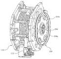
도 3a 및 도 3b는 각각 본 발명의 차량의 엔진 직결형 발전 장치를 엔진측 커플러 및 변속기측 커플러 방향에서 본 사시도.
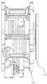
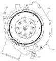
도 4a, 도 4b 및 도 4c는 각각 본 발명의 차량의 엔진 직결형 발전 장치의 정면도, 좌측면도 및 우측면도.
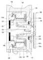
도 5는 본 발명의 차량의 엔진 직결형 발전 장치의 분리 사시도.
도 6은 도 4a에서 A-A선을 취하여 본 종 단면도.
도 7은 본 발명의 차량의 엔진 직결형 발전 장치가 엔진 및 변속기에 결합된 상태를 개략적으로 보인 단면도.1 is a block diagram illustrating a power generation system of a conventional vehicle.
2 is a block diagram illustrating a power generation system of a vehicle provided with an engine direct type power generation apparatus according to the present invention.
3A and 3B are respectively a perspective view of the engine direct-connected power generation device of the vehicle of the present invention viewed from the engine side coupler and the transmission side coupler directions.
4A, 4B and 4C are respectively a front view, a left side view and a right side view of an engine direct type generator of the vehicle of the present invention.
5 is an exploded perspective view of an engine direct generator of the vehicle of the present invention.
6 is a longitudinal cross-sectional view taken along line AA in FIG. 4A;
Figure 7 is a schematic cross-sectional view showing a state in which the engine direct-connected power generation device of the vehicle of the present invention coupled to the engine and the transmission.
이하에는 첨부한 도면을 참조하여 본 발명의 차량의 엔진 직결형 발전 장치의 바람직한 실시예에 대해 상세하게 설명한다.Hereinafter, with reference to the accompanying drawings will be described in detail a preferred embodiment of the engine direct type generator of the vehicle of the present invention.
도 2는 본 발명의 엔진 직결형 발전 장치를 구비한 차량의 발전 계통을 설명하기 위한 블록 구성도인바, 도 1과 동일한 구성에는 동일한 참조번호를 부여하고 그 상세한 설명을 생략한다. 도 2에 도시한 바와 같이, 본 발명의 엔진 직결형 발전 장치에 따르면, 종래 차량의 알터네이터와는 별개로 엔진(10)과 변속기(20)의 연결축 사이에 종래 알터네이터에 비해 상대적으로 큰 전력, 예를 들어 10㎾ 내외의 대전력을 생산하는 발전기(100), 바람직하게는 교류 발전기가 직접 결합된다.FIG. 2 is a block diagram illustrating a power generation system of a vehicle having an engine-directed generator according to the present invention. The same configuration as that in FIG. 1 is given the same reference numeral, and detailed description thereof will be omitted. As shown in FIG. 2, according to the engine direct-type power generation apparatus of the present invention, a power which is relatively larger than that of the conventional alternator between the connecting shaft of the
결과적으로, 본 발명에 따르면 엔진(10)과 발전기(100) 및 변속기(20)가 직렬로 연결되는데, 차량의 주행시에는 통상적으로 발전기(100)에서 발생된 전력이 사용되지 않고 엔진의 공회전 상태, 즉 아이들링 상태에서 발전기(100)에서 발생된 전력이 사용된다(물론 주행시에도 사용될 수 있을 것이다). 이와 같이 차량이 주행중이어서 발전기(100)가 무부하로 동작하는 경우에는 비록 엔진(10)과 변속기(20) 사이에 발전기(100)가 개재된다 하더라도 엔진(10)에서 발생된 동력이 거의 손실됨이 없이 변속기(20)에 전달되게 된다.As a result, according to the present invention, the
도 3a 및 도 3b는 각각 본 발명의 차량의 엔진 직결형 발전 장치를 엔진측 커플러 및 변속기측 커플러 방향에서 본 사시도이고, 도 4a, 도 4b 및 도 4c는 각각 본 발명의 차량의 엔진 직결형 발전 장치의 정면도, 좌측면도 및 우측면도이다. 도 5는 본 발명의 차량의 엔진 직결형 발전 장치의 분리 사시도이고, 도 6은 도 4a에서 A-A선을 취하여 본 종 단면도이다.3A and 3B are perspective views of an engine direct type generator of the vehicle of the present invention as viewed from an engine side coupler and a transmission side coupler, respectively, and FIGS. 4A, 4B, and 4C are respectively an engine direct type generator of a vehicle of the present invention; Front, left and right side views of the device. 5 is an exploded perspective view of an engine direct generator of the vehicle of the present invention, and FIG. 6 is a longitudinal cross-sectional view taken along line A-A of FIG. 4A.
도 3 내지 도 6에 도시한 바와 같이, 본 발명의 차량의 엔진 직결형 발전기는 가로로 누은 형상의 중공의 원통체로 이루어진 외부 하우징(110); 가로로 누은 형상의 중공의 통체로 이루어지며 복수의 고정자 코일을 지지한 채로 외부 하우징(110)의 내부에 삽입 설치되는 고정자 하우징(122)과 고정자 하우징(122)의 내주면을 따라 고정 설치되는 복수의 고정자 코일 뭉치(124)로 이루어진 고정자 조립체(120); 중심에 회전자 샤프트(134)가 구비된 원통체로 이루어진 회전자 코어(132)와 회전자 코어(132)의 외주면을 따라 고정 설치되는 복수의 자석(136), 예를 들어 영구자석으로 이루어져서 고정자 조립체(120)의 내측에 회전 가능하게 설치되는 회전자 조립체(130); 회전자 샤프트(134)의 엔진측 단부와 엔진(10)의 출력단 사이에 개재되어 발전기(100)와 엔진(10) 사이에서 발생하는 축하중을 완화시키는 엔진측 커플러(140) 및 회전자 샤프트(134)의 변속기측 단부와 변속기(20)의 입력단 사이에 개재되어 발전기(100)와 변속기(20) 사이에서 발생하는 축하중을 완화시키는 변속기측 커플러(150)를 포함하여 이루어진다.As shown in Figures 3 to 6, the engine direct type generator of the vehicle of the present invention includes an
전술한 구성에서, 외부 하우징(110)은 금속 재질, 예를 들어 알루미늄을 사용한 주조 또는 다이캐스팅 공법에 의해 제작될 수 있는데, 적소에는 고정자 조립체(120)를 냉각시키는 냉각수의 순환을 위한 냉각수 유입구(112)와 냉각수 유출구(미도시)가 마련되어 있다. 외부 하우징(110)에는 또한 고정자 조립체(120)에서 발생된 3상 교류 전기가 출력되는 터미널 및 외부 하우징(110) 내부에 설치되어 회전자 조립체(130)의 회전각도(회전수)를 감지하는 리졸버의 센싱값이 출력되는 센서 출력 터미널이 통합되어 있는 터미널 박스(114)가 마련되어 있다.In the above-described configuration, the
다음으로 고정자 하우징(122) 역시 금속 재질, 예를 들어 알루미늄을 주조 또는 다이캐스팅하여 제작될 수 있는데, 그 외주면에는 외주면을 나선형으로 복수 회(回) 감싸는 형태의 홈으로 이루어진 냉각수 순환홈(122a)이 형성되어 있다. 이러한 구조에서, 고정자 하우징(122)의 외주면이 외부 하우징(110)의 내주면에 밀착 결합됨으로써 냉각수 순환홈(122a)이 냉각수 순환로로 기능하게 된다. 외부 하우징(110)의 냉각수 유입구(112)와 냉각수 유출구는 각각 고정자 하우징(122)의 냉각수 순환홈(122a)의 일측 단부 및 타측 단부와 연통되어 있다.Next, the
고정자 하우징(122)에는 그 내주면을 따라 복수의 고정자 코일 뭉치(124)가 고정적으로 설치되는데, 이러한 각각의 고정자 코일 뭉치(124)는 코일이 보빈에 권취된 채로 고정자 코어에 고정되어 이루어진다.A plurality of
다음으로 회전자 조립체(130)는 원주를 따라 복수의 수납 포켓이 형성되어 있는 회전자 코어(132), 회전자 코어(132)의 각 수납 포켓에 수납되어 고정되는 영구자석(136) 및 회전자 코어(132)의 내주면에 회전자 코어(132)와 함께 회전하도록 결합, 예를 들어 키 겹합되는 회전자 샤프트(134)를 포함하여 이루어진다.Next, the
회전자 샤프트(134)는 다시 회전자 코어(132)가 삽입되는 외주면으로 이루어진 회전자코어 삽입부(134a), 회전자코어 삽입부(134a)의 좌측에 회전자코어 삽입부(134a)와 일체로 형성되되 외주면에는 키결합용 기어가 형성되어 있는 엔진측 키기어부(134b) 및 회전자코어 삽입부(134a)의 중심을 가로지르는 중심축의 우측단부에 형성되고 외주면에는 키결합용 기어가 형성되어 있는 변속기측 키기어부(134c)를 포함하여 이루어질 수 있다.The
회전자코어 삽입부(134a)는 좌측이 폐쇄되고 우측은 개방된 원통체로 이루어지고 중심에는 전술한 바와 같이 변속기측 키기어부(134c)를 형성하기 위한 중심축이 가로지르는데, 상기 중심축과 회전자코어 삽입부(134a) 사이에 형성된 공간에는 회전자 조립체(130)를 외부 하우징(110)에 대해 마찰없이 회전하도록 결합하는 베어링, 예를 들어 볼 베어링(138)이 설치되어 있다.The rotor
한편, 엔진(10)의 출력축을 발전기(100)의 회전자 조립체(130)에 연결하는 엔진측 커플러(140)는 내주면에 기어(142a)가 형성되어 있는 중공의 결합용 원통부(142)와 결합용 원통부(142)의 일단, 즉 좌측단에 외부를 향하도록 일체로 형성되어 엔진측 커플러(140)가 회전자 조립체(130)와 함께 회전하도록 엔진측 커플러(140)를 회전자 조립체(130)에 고정하는 브라켓(144)으로 이루어질 수 있다. 결합용 원통부(142)의 내주면에 형성된 엔진측커플러 기어(142a)는 비록 물리적으로는 동일 형상 및 동일 구조로 이루어져 있으나 기능적으로는 회전자 샤프트(134)의 엔진측 키기어부(134b)에 키결합되는 키결합용 기어부와 엔진(10)의 출력 샤프트에 스플라인 결합되는 스플라인 결합용 기어부로 구분될 수 있을 것이다.On the other hand, the
전술한 구성에 의해 엔진측 커플러(140)는 상기 키결합용 기어부가 회전자 샤프트(134)의 엔진측 키기어부(134b)에 키결합된 채로 회전자 조립체(130)에 고정된다. 한편, 엔진측 커플러(140)의 상기 스플라인 결합용 기어부는 엔진(10)의 출력 샤프트에 스플라인 결합됨으로써 회전자 조립체(130)에 고정되어 있는 엔진측 커플러(140)가 엔진(10)의 출력 샤프트에 대해 전후로 섭동이 가능하고, 결과적으로 조립 공차에 따라 발전기(100)의 회전자 샤프트(134)에 가해질 수 있는 축방향 하중을 무리 없이 흡수하게 된다. 결과적으로, 상기 스플라인 결합용 기어부의 좌우 길이는 조립 공차보다 크게 형성되어야 한다.By the above-described configuration, the
다음으로, 변속기측 커플러(150)는 속이 빈 원통체로 이루어지고 내주면에는 회전자 샤프트(134)의 변속기측 키기어부(134c)에 키결합되는 키결합용 기어가 형성되어 있는 키결합용 보어(152) 및 탄성을 갖는 원판으로 이루어져서 키결합용 보어(152)의 우측단부에 고정 결합, 예를 들어 볼팅 결합되는 탄성 플레이트(154)를 포함하여 이루어진다.Next, the
전술한 구성에서, 탄성 플레이트(154)는 판스프링의 기능을 수행할 수 있도록 탄성력이 매우 큰 금속 판재로 구현하는 것이 바람직한바, 이러한 탄성 플레이트(154)의 외주 가장자리에는 탄성 플레이트(154)의 강도를 보강하기 위한 수직 림(154a)이 형성되어 있다. 도면에서 참조번호 154b는 변속기측 입력 샤프트와 탄성 플레이트(154)를 고정시키기 위한 볼트 관통공을 나타내는바, 탄성 플레이트(154)가 보다 큰 탄성을 갖기 위해서는 이러한 볼트 관통공이 탄성 플레이트(154)에 그 중심축보다는 수직 림에 더 근접하도록 형성하는 것이 바람직하다.In the above-described configuration, the
한편, 차량의 시동이 걸린 상태에서는 변속기(20)의 토크 컨버터(torque converter)가 축방향으로 줄었다 늘었다를 반복하게 되고, 이러한 축방향 변위에 따라 발전기(100)의 회전자 샤프트(134)에 축하중이 인가되어 발전기(100)가 손상될 수도 있는데, 본 발명에서는 이러한 축방향 하중을 변속기측 커플러(150)의 탄성 플레이트(154)에 의해 흡수함으로써 발전기(100)의 회전자 샤프트(134)에 축방향 하중이 인가되는 것을 방지할 수 있다.On the other hand, when the vehicle is started, the torque converter of the
도 7은 본 발명의 차량의 엔진 직결형 발전 장치가 엔진 및 변속기에 결합된 상태를 개략적으로 보인 단면도이다. 도 7에 도시한 바와 같이, 본 발명의 차량의 엔진 직결형 발전 장치에 따르면, 엔진측 커플러(140)의 상기 스플라인 결합용 기어부가 엔진(10)의 출력 샤프트(es)에 스플라인 결합됨으로써 회전자 조립체(130)에 고정되어 있는 엔진측 커플러(140)가 엔진(10)의 출력 샤프트(es)에 대해 전후로 섭동이 가능하고, 결과적으로 조립 공차에 따라 발전기(100)의 회전자 샤프트(134)에 가해질 수 있는 축방향 하중을 무리 없이 흡수하게 된다. FIG. 7 is a schematic cross-sectional view illustrating a state in which an engine direct-type generator of the vehicle is coupled to an engine and a transmission. FIG. As shown in FIG. 7, according to the engine direct type power generation apparatus of the vehicle of the present invention, the spline coupling gear portion of the
이와 함께 변속기측 입력 샤프트(ts)는 변속기측 커플러(150)의 탄성 플레이트(154)에 결합되기 때문에 비록 변속기(20)의 토크 컨버터에 의해 축 방향 하중이 인가되더라도 탄성 플레이트(154)의 판스프링 작용에 의해 이러한 축 방향 하중이 흡수되고, 결과적으로 이러한 축방향 하중이 발전기(100)의 회전자 샤프트(134)에는 인가되지 않게 된다.In addition, since the transmission side input shaft ts is coupled to the
이상, 첨부한 도면을 참조하여 본 발명의 차량의 엔진 직결형 발전 장치의 바람직한 실시예에 대하여 상세히 설명하였으나 이는 예시에 불과한 것이며, 본 발명의 기술적 사상의 범주 내에서 다양한 변형과 변경이 가능할 것이다. 따라서, 본 발명의 권리범위는 이하의 특허청구범위의 기재에 의하여 정해져야 할 것이다.As mentioned above, although the preferred embodiment of the engine direct type generator of the vehicle of the present invention was described in detail with reference to the accompanying drawings, this is only an illustration, and various modifications and changes can be made within the scope of the technical idea of the present invention. Accordingly, the scope of the present invention should be determined by the following claims.
10: 엔진,20: 변속기,
30: 구동 풀리,40: 종동 풀리,
50: 벨트,60: 발전기,
62: 고정자,64: 회전자,
70: 배터리,100: 발전기,
110: 외부 하우징,112: 냉각수 유입구,
114: 터미널 박스,120 : 고정자 조립체,
122: 고정자 하우징,122a: 냉각수 순환홈,
124: 고정자 코일 뭉치,130: 회전자 조립체,
132: 회전자 코어,134: 회전자 샤프트,
134a: 회전자코어 삽입부,134b: 엔진측 키기어부,
134c: 변속기측 키기어부,136: 영구자석,
138: 볼베어링,140: 엔진측 커플러,
142: 결합용 원통부,142a: 기어,
144: 브라켓,150: 변속기측 커플러,
152: 보어,154: 탄성 플레이트,
154a: 수직 림,154b: 볼트 관통공10: engine, 20: gearbox,
30: driven pulley, 40: driven pulley,
50: belt, 60: generator,
62: stator, 64: rotor,
70: battery, 100: generator,
110: outer housing, 112: coolant inlet,
114: terminal box, 120: stator assembly,
122: stator housing, 122a: cooling water circulation groove,
124: bundle of stator coils, 130: rotor assembly,
132: rotor core, 134: rotor shaft,
134a: rotor core insertion part, 134b: engine side key gear part,
134c: transmission gear unit, 136: permanent magnet,
138: ball bearing, 140: engine side coupler,
142: cylindrical portion for engagement, 142a: gear,
144: bracket, 150: transmission side coupler,
152: bore, 154: elastic plate,
154a: vertical rim, 154b: bolt through hole
Claims (3)
Translated fromKorean가로로 누은 형상의 중공의 원통체로 이루어진 외부 하우징;
가로로 누은 형상의 중공의 통체로 이루어지며 복수의 고정자 코일을 지지한 채로 상기 외부 하우징의 내부에 삽입 설치되는 고정자 하우징과 상기 고정자 하우징의 내주면을 따라 고정 설치되는 복수의 고정자 코일 뭉치로 이루어진 고정자 조립체;
중심에 회전자 샤프트가 구비된 원통체로 이루어진 회전자 코어와 상기 회전자 코어의 외주면을 따라 고정 설치되는 복수의 자석으로 이루어져서 상기 고정자 조립체의 내측에 회전 가능하게 설치되는 회전자 조립체;
상기 회전자 샤프트의 엔진측 단부와 엔진의 출력단 사이에 전후로 섭동 가능하도록 개재되어 발전 장치와 엔진 사이에서 발생하는 축하중을 완화시키는 엔진측 커플러 및
상기 회전자 샤프트의 변속기측 단부와 변속기의 입력단 사이에 개재되어 발전 장치와 변속기 사이에서 발생하는 축하중을 완화시키는 변속기측 커플러를 포함하되,
상기 외부 하우징은 상기 고정자 조립체를 냉각시키는 냉각수의 순환을 위한 냉각수 유입구와 냉각수 유출구를 구비하고,
상기 고정자 하우징의 외주면에는 외주면을 나선형으로 복수 회(回) 감싸는 형태의 홈으로 이루어진 냉각수 순환홈이 형성되어 있되 상기 고정자 하우징의 외주면이 상기 외부 하우징의 내주면에 밀착 결합됨으로써 상기 냉각수 순환홈이 냉각수 순환로로 기능하도록 된 것을 특징으로 하는 차량의 엔진 직결형 발전 장치.An alternator that supplies drive power to the vehicle's electronics is applied to vehicles connected in parallel between the engine and the transmission,
An outer housing made of a hollow cylindrical body having a horizontally laid shape;
A stator assembly composed of a hollow cylinder having a horizontal shape, and comprising a stator housing inserted into an interior of the outer housing while supporting a plurality of stator coils, and a plurality of stator coil bundles fixedly installed along an inner circumferential surface of the stator housing. ;
A rotor assembly comprising a rotor core formed of a cylindrical body having a rotor shaft at a center thereof, and a plurality of magnets fixedly installed along an outer circumferential surface of the rotor core to be rotatably installed inside the stator assembly;
An engine-side coupler interposed between the engine-side end of the rotor shaft and the output end of the engine so as to perturb back and forth to alleviate the celebration occurring between the power generator and the engine;
A transmission side coupler interposed between the transmission side end of the rotor shaft and the input end of the transmission to mitigate celebrating occurring between the power generation device and the transmission,
The outer housing has a coolant inlet and a coolant outlet for circulation of coolant for cooling the stator assembly,
Cooling water circulation groove is formed on the outer circumferential surface of the stator housing is formed of a groove of a shape that surrounds the outer circumferential surface a plurality of times in a spiral manner, but the outer circumferential surface of the stator housing is in close contact with the inner circumferential surface of the outer housing is the cooling water circulation groove Engine direct-connected power generation device, characterized in that to function as.
상기 회전자 조립체는 원주를 따라 복수의 수납 포켓이 형성되어 있는 회전자 코어, 상기 회전자 코어의 각각의 상기 수납 포켓에 수납되어 고정되는 영구자석 및 상기 회전자 코어의 내주면에 상기 회전자 코어와 함께 회전하도록 결합된 회전자 샤프트를 포함하여 이루어지되,
상기 회전자 샤프트는 상기 회전자 코어가 삽입되는 외주면으로 이루어진 회전자코어 삽입부, 상기 회전자코어 삽입부의 좌측에 상기 회전자코어 삽입부와 일체로 형성되고 외주면에는 키결합용 기어가 형성되어 있는 엔진측 키기어부 및 상기 회전자코어 삽입부의 중심을 가로지르는 중심축의 우측단부에 형성되고 외주면에는 키결합용 기어가 형성되어 있는 변속기측 키기어부를 포함하여 이루어진 것을 특징으로 하는 차량의 엔진 직결형 발전 장치.3. The method of claim 2,
The rotor assembly may include a rotor core having a plurality of storage pockets formed along a circumference thereof, a permanent magnet accommodated in and fixed to each of the storage pockets of the rotor core, and the rotor core on an inner circumferential surface of the rotor core. Comprising a rotor shaft coupled to rotate together,
The rotor shaft is formed of a rotor core insertion portion consisting of an outer circumferential surface into which the rotor core is inserted, integrally with the rotor core inserting portion on the left side of the rotor core inserting portion, and a key coupling gear is formed on the outer circumferential surface thereof. An engine direct type power generation unit comprising a transmission side key gear unit formed at a right end portion of a central shaft that crosses the center of the engine side key gear unit and the rotor core insertion unit, and a key coupling gear formed at an outer circumferential surface thereof. Device.
Priority Applications (1)
| Application Number | Priority Date | Filing Date | Title |
|---|---|---|---|
| KR1020130081655AKR101322358B1 (en) | 2013-07-11 | 2013-07-11 | Electricity generating apparatus coupled directly with engine of vehicle |
Applications Claiming Priority (1)
| Application Number | Priority Date | Filing Date | Title |
|---|---|---|---|
| KR1020130081655AKR101322358B1 (en) | 2013-07-11 | 2013-07-11 | Electricity generating apparatus coupled directly with engine of vehicle |
Publications (1)
| Publication Number | Publication Date |
|---|---|
| KR101322358B1true KR101322358B1 (en) | 2013-10-28 |
Family
ID=49639334
Family Applications (1)
| Application Number | Title | Priority Date | Filing Date |
|---|---|---|---|
| KR1020130081655AActiveKR101322358B1 (en) | 2013-07-11 | 2013-07-11 | Electricity generating apparatus coupled directly with engine of vehicle |
Country Status (1)
| Country | Link |
|---|---|
| KR (1) | KR101322358B1 (en) |
Cited By (1)
| Publication number | Priority date | Publication date | Assignee | Title |
|---|---|---|---|---|
| KR101590696B1 (en) | 2014-03-26 | 2016-02-02 | 현대로템 주식회사 | Generator for vehicle |
Citations (1)
| Publication number | Priority date | Publication date | Assignee | Title |
|---|---|---|---|---|
| KR20110004777A (en)* | 2009-07-08 | 2011-01-14 | 해밀턴 선드스트랜드 코포레이션 | Overlapping Exciter and Main Generator Stage for Winding Field Generators |
- 2013
- 2013-07-11KRKR1020130081655Apatent/KR101322358B1/enactiveActive
Patent Citations (1)
| Publication number | Priority date | Publication date | Assignee | Title |
|---|---|---|---|---|
| KR20110004777A (en)* | 2009-07-08 | 2011-01-14 | 해밀턴 선드스트랜드 코포레이션 | Overlapping Exciter and Main Generator Stage for Winding Field Generators |
Cited By (1)
| Publication number | Priority date | Publication date | Assignee | Title |
|---|---|---|---|---|
| KR101590696B1 (en) | 2014-03-26 | 2016-02-02 | 현대로템 주식회사 | Generator for vehicle |
Similar Documents
| Publication | Publication Date | Title |
|---|---|---|
| US10500937B2 (en) | Electric drive unit, hybrid drive device, and vehicle | |
| CN101391581B (en) | Powertrain with torque converter-mounted generator for multiple voltage electrical power and method for assembling same | |
| US6462430B1 (en) | Hybrid car and dynamo-electric machine | |
| US20040232702A1 (en) | Ring type starter/generator | |
| US20100237725A1 (en) | Rotating electric machine and drive device | |
| EP1902945B1 (en) | Power generating and propelling system of vessel | |
| US7479716B2 (en) | Cooling system for a stator assembly | |
| EP3493372B1 (en) | Integrated starter generator and hybrid power system | |
| JP5188592B2 (en) | Generator motor cooling structure and generator motor | |
| CN104659959A (en) | Belt-Driven Starter-Generator | |
| US9221326B2 (en) | Drive system for a land craft | |
| KR20180080059A (en) | Mechanical drive to the motor and alternator | |
| US9915198B2 (en) | Belt pulley arrangement for a belt drive for driving auxiliary units of a motor vehicle and method for driving an auxiliary unit of a motor vehicle connected via a belt pulley arrangement | |
| US6736228B2 (en) | Electric machine with integrated wet clutches | |
| KR101316601B1 (en) | Engine coupling apparatus for electricity generating apparatus coupled directly with engine of vehicle | |
| EP1860759A2 (en) | Axial Gap alternator | |
| JP2004232560A (en) | Auxiliary drive for internal combustion engine | |
| KR101322358B1 (en) | Electricity generating apparatus coupled directly with engine of vehicle | |
| JP2008032135A (en) | Auxiliary machine driving device | |
| KR101316602B1 (en) | Transmission coupling apparatus for electricity generating apparatus coupled directly with engine of vehicle | |
| KR101590696B1 (en) | Generator for vehicle | |
| CN117559716A (en) | Compact structure's start-up rechargeable diesel engine power output structure | |
| CN110397536A (en) | Started with no brush device assembly on axis | |
| KR20140004313A (en) | Cooling structure for motor rotator | |
| KR20150121967A (en) | Starter-generator using flywheel of vehicle |
Legal Events
| Date | Code | Title | Description |
|---|---|---|---|
| A201 | Request for examination | ||
| PA0109 | Patent application | Patent event code:PA01091R01D Comment text:Patent Application Patent event date:20130711 | |
| PA0201 | Request for examination | ||
| A302 | Request for accelerated examination | ||
| PA0302 | Request for accelerated examination | Patent event date:20130913 Patent event code:PA03022R01D Comment text:Request for Accelerated Examination Patent event date:20130711 Patent event code:PA03021R01I Comment text:Patent Application | |
| E902 | Notification of reason for refusal | ||
| PE0902 | Notice of grounds for rejection | Comment text:Notification of reason for refusal Patent event date:20130930 Patent event code:PE09021S01D | |
| E701 | Decision to grant or registration of patent right | ||
| PE0701 | Decision of registration | Patent event code:PE07011S01D Comment text:Decision to Grant Registration Patent event date:20131018 | |
| GRNT | Written decision to grant | ||
| PR0701 | Registration of establishment | Comment text:Registration of Establishment Patent event date:20131021 Patent event code:PR07011E01D | |
| PR1002 | Payment of registration fee | Payment date:20131021 End annual number:3 Start annual number:1 | |
| PG1601 | Publication of registration | ||
| FPAY | Annual fee payment | Payment date:20160803 Year of fee payment:4 | |
| PR1001 | Payment of annual fee | Payment date:20160803 Start annual number:4 End annual number:4 | |
| FPAY | Annual fee payment | Payment date:20170823 Year of fee payment:5 | |
| PR1001 | Payment of annual fee | Payment date:20170823 Start annual number:5 End annual number:5 | |
| FPAY | Annual fee payment | Payment date:20180919 Year of fee payment:6 | |
| PR1001 | Payment of annual fee | Payment date:20180919 Start annual number:6 End annual number:6 | |
| FPAY | Annual fee payment | Payment date:20191016 Year of fee payment:7 | |
| PR1001 | Payment of annual fee | Payment date:20191016 Start annual number:7 End annual number:7 | |
| PR1001 | Payment of annual fee | Payment date:20201214 Start annual number:8 End annual number:8 | |
| PR1001 | Payment of annual fee | Payment date:20221026 Start annual number:10 End annual number:10 | |
| PR1001 | Payment of annual fee | Payment date:20231016 Start annual number:11 End annual number:11 |