KR101320918B1 - Wire feeding apparatus for wire bonders - Google Patents
Wire feeding apparatus for wire bondersDownload PDFInfo
- Publication number
- KR101320918B1 KR101320918B1KR20110123447AKR20110123447AKR101320918B1KR 101320918 B1KR101320918 B1KR 101320918B1KR 20110123447 AKR20110123447 AKR 20110123447AKR 20110123447 AKR20110123447 AKR 20110123447AKR 101320918 B1KR101320918 B1KR 101320918B1
- Authority
- KR
- South Korea
- Prior art keywords
- wire
- bonding
- clamp
- bonder
- pneumatic device
- Prior art date
- Legal status (The legal status is an assumption and is not a legal conclusion. Google has not performed a legal analysis and makes no representation as to the accuracy of the status listed.)
- Expired - Fee Related
Links
Images


Classifications
- H—ELECTRICITY
- H01—ELECTRIC ELEMENTS
- H01L—SEMICONDUCTOR DEVICES NOT COVERED BY CLASS H10
- H01L24/00—Arrangements for connecting or disconnecting semiconductor or solid-state bodies; Methods or apparatus related thereto
- H01L24/74—Apparatus for manufacturing arrangements for connecting or disconnecting semiconductor or solid-state bodies
- H01L24/78—Apparatus for connecting with wire connectors
- B—PERFORMING OPERATIONS; TRANSPORTING
- B23—MACHINE TOOLS; METAL-WORKING NOT OTHERWISE PROVIDED FOR
- B23K—SOLDERING OR UNSOLDERING; WELDING; CLADDING OR PLATING BY SOLDERING OR WELDING; CUTTING BY APPLYING HEAT LOCALLY, e.g. FLAME CUTTING; WORKING BY LASER BEAM
- B23K20/00—Non-electric welding by applying impact or other pressure, with or without the application of heat, e.g. cladding or plating
- B23K20/002—Non-electric welding by applying impact or other pressure, with or without the application of heat, e.g. cladding or plating specially adapted for particular articles or work
- B23K20/004—Wire welding
- B23K20/005—Capillary welding
- B—PERFORMING OPERATIONS; TRANSPORTING
- B23—MACHINE TOOLS; METAL-WORKING NOT OTHERWISE PROVIDED FOR
- B23K—SOLDERING OR UNSOLDERING; WELDING; CLADDING OR PLATING BY SOLDERING OR WELDING; CUTTING BY APPLYING HEAT LOCALLY, e.g. FLAME CUTTING; WORKING BY LASER BEAM
- B23K2101/00—Articles made by soldering, welding or cutting
- B23K2101/36—Electric or electronic devices
- B23K2101/42—Printed circuits
- H—ELECTRICITY
- H01—ELECTRIC ELEMENTS
- H01L—SEMICONDUCTOR DEVICES NOT COVERED BY CLASS H10
- H01L2224/00—Indexing scheme for arrangements for connecting or disconnecting semiconductor or solid-state bodies and methods related thereto as covered by H01L24/00
- H01L2224/01—Means for bonding being attached to, or being formed on, the surface to be connected, e.g. chip-to-package, die-attach, "first-level" interconnects; Manufacturing methods related thereto
- H01L2224/42—Wire connectors; Manufacturing methods related thereto
- H01L2224/44—Structure, shape, material or disposition of the wire connectors prior to the connecting process
- H01L2224/45—Structure, shape, material or disposition of the wire connectors prior to the connecting process of an individual wire connector
- H01L2224/45001—Core members of the connector
- H01L2224/45099—Material
- H01L2224/451—Material with a principal constituent of the material being a metal or a metalloid, e.g. boron (B), silicon (Si), germanium (Ge), arsenic (As), antimony (Sb), tellurium (Te) and polonium (Po), and alloys thereof
- H01L2224/45138—Material with a principal constituent of the material being a metal or a metalloid, e.g. boron (B), silicon (Si), germanium (Ge), arsenic (As), antimony (Sb), tellurium (Te) and polonium (Po), and alloys thereof the principal constituent melting at a temperature of greater than or equal to 950°C and less than 1550°C
- H01L2224/45144—Gold (Au) as principal constituent
- H—ELECTRICITY
- H01—ELECTRIC ELEMENTS
- H01L—SEMICONDUCTOR DEVICES NOT COVERED BY CLASS H10
- H01L2224/00—Indexing scheme for arrangements for connecting or disconnecting semiconductor or solid-state bodies and methods related thereto as covered by H01L24/00
- H01L2224/01—Means for bonding being attached to, or being formed on, the surface to be connected, e.g. chip-to-package, die-attach, "first-level" interconnects; Manufacturing methods related thereto
- H01L2224/42—Wire connectors; Manufacturing methods related thereto
- H01L2224/44—Structure, shape, material or disposition of the wire connectors prior to the connecting process
- H01L2224/45—Structure, shape, material or disposition of the wire connectors prior to the connecting process of an individual wire connector
- H01L2224/45001—Core members of the connector
- H01L2224/45099—Material
- H01L2224/451—Material with a principal constituent of the material being a metal or a metalloid, e.g. boron (B), silicon (Si), germanium (Ge), arsenic (As), antimony (Sb), tellurium (Te) and polonium (Po), and alloys thereof
- H01L2224/45138—Material with a principal constituent of the material being a metal or a metalloid, e.g. boron (B), silicon (Si), germanium (Ge), arsenic (As), antimony (Sb), tellurium (Te) and polonium (Po), and alloys thereof the principal constituent melting at a temperature of greater than or equal to 950°C and less than 1550°C
- H01L2224/45147—Copper (Cu) as principal constituent
- H—ELECTRICITY
- H01—ELECTRIC ELEMENTS
- H01L—SEMICONDUCTOR DEVICES NOT COVERED BY CLASS H10
- H01L2224/00—Indexing scheme for arrangements for connecting or disconnecting semiconductor or solid-state bodies and methods related thereto as covered by H01L24/00
- H01L2224/74—Apparatus for manufacturing arrangements for connecting or disconnecting semiconductor or solid-state bodies and for methods related thereto
- H01L2224/78—Apparatus for connecting with wire connectors
- H01L2224/7825—Means for applying energy, e.g. heating means
- H01L2224/783—Means for applying energy, e.g. heating means by means of pressure
- H01L2224/78301—Capillary
- H—ELECTRICITY
- H01—ELECTRIC ELEMENTS
- H01L—SEMICONDUCTOR DEVICES NOT COVERED BY CLASS H10
- H01L2224/00—Indexing scheme for arrangements for connecting or disconnecting semiconductor or solid-state bodies and methods related thereto as covered by H01L24/00
- H01L2224/74—Apparatus for manufacturing arrangements for connecting or disconnecting semiconductor or solid-state bodies and for methods related thereto
- H01L2224/78—Apparatus for connecting with wire connectors
- H01L2224/786—Means for supplying the connector to be connected in the bonding apparatus
- H01L2224/78611—Feeding means
- H—ELECTRICITY
- H01—ELECTRIC ELEMENTS
- H01L—SEMICONDUCTOR DEVICES NOT COVERED BY CLASS H10
- H01L2224/00—Indexing scheme for arrangements for connecting or disconnecting semiconductor or solid-state bodies and methods related thereto as covered by H01L24/00
- H01L2224/74—Apparatus for manufacturing arrangements for connecting or disconnecting semiconductor or solid-state bodies and for methods related thereto
- H01L2224/78—Apparatus for connecting with wire connectors
- H01L2224/786—Means for supplying the connector to be connected in the bonding apparatus
- H01L2224/78621—Holding means, e.g. wire clampers
- H01L2224/78631—Means for wire tension adjustments
- H—ELECTRICITY
- H01—ELECTRIC ELEMENTS
- H01L—SEMICONDUCTOR DEVICES NOT COVERED BY CLASS H10
- H01L24/00—Arrangements for connecting or disconnecting semiconductor or solid-state bodies; Methods or apparatus related thereto
- H01L24/01—Means for bonding being attached to, or being formed on, the surface to be connected, e.g. chip-to-package, die-attach, "first-level" interconnects; Manufacturing methods related thereto
- H01L24/42—Wire connectors; Manufacturing methods related thereto
- H01L24/44—Structure, shape, material or disposition of the wire connectors prior to the connecting process
- H01L24/45—Structure, shape, material or disposition of the wire connectors prior to the connecting process of an individual wire connector
- H—ELECTRICITY
- H01—ELECTRIC ELEMENTS
- H01L—SEMICONDUCTOR DEVICES NOT COVERED BY CLASS H10
- H01L2924/00—Indexing scheme for arrangements or methods for connecting or disconnecting semiconductor or solid-state bodies as covered by H01L24/00
- H01L2924/0001—Technical content checked by a classifier
- H01L2924/00014—Technical content checked by a classifier the subject-matter covered by the group, the symbol of which is combined with the symbol of this group, being disclosed without further technical details
- H—ELECTRICITY
- H01—ELECTRIC ELEMENTS
- H01L—SEMICONDUCTOR DEVICES NOT COVERED BY CLASS H10
- H01L2924/00—Indexing scheme for arrangements or methods for connecting or disconnecting semiconductor or solid-state bodies as covered by H01L24/00
- H01L2924/01—Chemical elements
- H01L2924/01029—Copper [Cu]
- H—ELECTRICITY
- H01—ELECTRIC ELEMENTS
- H01L—SEMICONDUCTOR DEVICES NOT COVERED BY CLASS H10
- H01L2924/00—Indexing scheme for arrangements or methods for connecting or disconnecting semiconductor or solid-state bodies as covered by H01L24/00
- H01L2924/01—Chemical elements
- H01L2924/01033—Arsenic [As]
- H—ELECTRICITY
- H01—ELECTRIC ELEMENTS
- H01L—SEMICONDUCTOR DEVICES NOT COVERED BY CLASS H10
- H01L2924/00—Indexing scheme for arrangements or methods for connecting or disconnecting semiconductor or solid-state bodies as covered by H01L24/00
- H01L2924/01—Chemical elements
- H01L2924/01079—Gold [Au]
Landscapes
- Engineering & Computer Science (AREA)
- Mechanical Engineering (AREA)
- Manufacturing & Machinery (AREA)
- Computer Hardware Design (AREA)
- Microelectronics & Electronic Packaging (AREA)
- Power Engineering (AREA)
- Wire Bonding (AREA)
Abstract
Translated fromKoreanDescription
Translated fromKorean본 발명은 와이어 본더(wire bonder)에 관한 것으로, 더욱 상세하게는 와이어 본더에 와이어를 공급하고 가이드 하기 위한 와이어 공급 장치 및 와이어 공급 방법에 관한 것이다.The present invention relates to a wire bonder, and more particularly, to a wire supply device and a wire supply method for supplying and guiding a wire to the wire bonder.
와이어 본더는 다이(die) 상의 전기적 접촉 패드와 기재 사이 또는 다른 다이들(dice) 상의 전기적 접촉 패드들 사이를 전기적으로 결선하기 위한 반도체 조립 및 패키징(packaging) 동안 사용된다. 와이어는 통상적으로 골드 와이어 또는 구리 와이어가 감겨진 와이어 스풀(wire spool)(와이어를 감는 태)로부터 캐피러리(capillary)와 같은 본딩 기구로 공급된다. 캐피러리는 상기 본딩 기구에서 와이어 본딩을 실행하기 위한 것이다.Wire bonders are used during semiconductor assembly and packaging to electrically connect between the electrical contact pads on the die and the substrate or between the electrical contact pads on other dice. Wire is typically supplied from a wire spool (wound wire) in which a gold wire or a copper wire is wound to a bonding mechanism such as a capillary. The capillary is for carrying out wire bonding in the bonding mechanism.
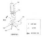
상기 와이어 스풀과 상기 캐피러리 간의 와이어 공급 경로를 따라, 상기 와이어는 와이어 본딩 동안 그 와이어의 공급을 제어하기 위한 공압 장치와 와이어 클램프(wire clamp)를 포함할 수 있는 다양한 장치들을 통과하게 된다. 도 1은 종래의 와이어 본더를 나타내는 측면도이다. 예를 들면, 골드 와이어 또는 구리 와이어 등의 본딩 와이어(100)는 와이어 스풀(미도시)로부터 상기 본딩 와이어(100)를 상향 또는 하향으로 이동시키기 위하여 상향 또는 하향의 수직 진공 흡입력을 인가하도록 작동하는 공압 장치(102)로 공급된다. 와이어 가이더(wire guider)(104)는 상기 공압 장치(102)로부터 다소 떨어진 거리에 위치되고, 상기 본딩 와이어(100)를 뽑아내고 경로를 따라 안내하기 위한 작은 구멍을 구비한다. 와이어 클램프(wire clamp)(106)는 상기 본딩 가이더(104) 아래에 위치되어 상기 본딩 와이어(100)의 이동을 저지하고자 할 때 상기 본딩 와이어(100)를 클램핑한다. 그런 다음, 상기 본딩 와이어(100)는 트랜스듀서 혼(transducer horn)(110)의 일단에 위치된 캐피러리(capiillary)(108)를 통과한다. 와이어 본딩은 상기 캐피러리(108)의 바닥 첨단부에서 실행된다.Along the wire feed path between the wire spool and the capacitor, the wire passes through various devices that may include a wire clamp and a pneumatic device to control the supply of the wire during wire bonding. 1 is a side view showing a conventional wire bonder. For example, bonding
이러한 종래의 와이어 본더 디자인의 결점은 상기 공압 장치(102)와 와이어 가이더(104) 사이에서 상대적으로 긴 한 가닥의 본딩 와이어(100)가 와이어를 구부러지게 하고 꼬임을 형성시키는 난기류에 노출된다는 것이다. 또한, 상기 본딩 와이어는 본딩 영역에서 오염 물질에 노출된다. 그 결과, 결함이 있는 와이어 본딩을 초래하여 와이어 루핑 성능(looping performance)이 좋지 못하게 된다.A drawback of this conventional wire bonder design is that a relatively long strand of
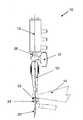
도 2는 상부 와이어 클램프(112)와 하부 와이어 클램프(106)를 포함하는 종래의 와이어 본더를 나타내는 측면도로서, 상기 와이어 클램프들을 통해 공급되는 와이어(100)에 대하여 허공에서 바람직하지 못한 폐해의 결과를 도시하고 있다. 상기 와이어 클램프들을 통해 공급되고 이들 사이에 유지되는 상기 본딩 와이어(100)는 와이어 본딩 동안 노출되고 이에 따라 난기류 및 오염 물질에 영향을 받게 된다. 또한, 상기 와이어(100)는 와이어 본딩 동안에 상기 와이어 본더의 이동으로 인한 가속력을 받게 된다. 이러한 상황이 필요 이상 크다면, 상기 가속력은 상기 상부 와이어 클램프(112)와 하부 와이어 클램프(106) 사이에서 노출된 한 가닥의 와이어(100)에서 그 와이어(100)를 구부러지게 하고 꼬임을 형성시킨다. 이는 와이어 루핑에 악영향을 주고, 와이어 본드들은 잘 형성되지 못하게 될 수 있다.FIG. 2 is a side view showing a conventional wire bonder including an
도 3은 와이어 본딩 동안, 수직 공급 경로로부터 벗어나 와이어 본더로 공급되는 와이어를 나타내는 종래의 와이어 본더의 측면도이다. 상기 와이어 가이더(104)는 그 와이어 가이더(104)와 상기 캐피러리(108) 사이에 위치된 상기 와이어 클램프(106)와 정렬된다. 이는 상기 와이어 가이더(104)와 캐피러리(108) 사이에서 갭(gap)을 많이 증가시켜 상기 와이어(100)는 수직 공급 경로로부터 상당히 벗어나게 되고, 이에 따라 와이어 루핑에 악영향을 주며, 결국은 와이어 본딩의 형성에 영향을 미치게 된다. 그러므로 와이어 본딩 성능을 향상시키기 위하여 상기 수직 공급 경로로부터 와이어(100)가 벗어나는 것을 감소시키는 것이 바람직하다. 또한, 전술한 바와 같이 난기류 및 오염 물질을 발생시키는 종래의 와이어 본더를 이용함으로써 일어나는 바람직하지 못한 문제들 없이 와이어 본더의 성능을 향상시키는 것이 바람직하다.3 is a side view of a conventional wire bonder showing the wire fed to the wire bonder away from the vertical feed path during wire bonding. The
따라서, 본 발명의 목적은 와이어 본더에 와이어를 효율적으로 공급하고, 와이어 본딩 동작에 대한 방해 작용을 감소시키며, 양질의 와이어 본딩의 형성을 증진시킬 수 있는 와이어 본딩 시스템 및 와이어 본딩 방법을 제공하고자 하는 데 있다.Accordingly, it is an object of the present invention to provide a wire bonding system and a wire bonding method that can efficiently supply wire to a wire bonder, reduce interference with wire bonding operations, and promote formation of good wire bonding. There is.
따라서, 본 발명은 와이어 본드들을 형성하기 위한 본딩 기구; 상기 본딩 기구로 와이어를 공급하기 위한 공압 장치; 상기 공압 장치와 본딩 기구 사이에서의 와이어 공급 경로를 따라 정렬되어 각각의 클램핑 지점에서 와이어를 클램핑하기 위한 상부 클램프와 하부 클램프; 및 상기 상부 클램프로부터 하부 클램프로 대체로 연장하고, 상기 와이어 공급 경로를 따라 상기 와이어를 에워싸며, 상기 와이어를 차폐 및 안내하도록 작동가능한 고정 중간 안내 챔버를 포함하는 와이어 본더를 제공한다.Accordingly, the present invention provides a bonding mechanism for forming wire bonds; A pneumatic device for supplying a wire to the bonding mechanism; An upper clamp and a lower clamp aligned along a wire supply path between the pneumatic device and the bonding mechanism to clamp the wire at each clamping point; And a fixed intermediate guide chamber extending generally from the upper clamp to the lower clamp, enclosing the wire along the wire supply path, and operable to shield and guide the wire.
이하에서는 본 발명의 일 실시예를 나타내는 첨부 도면들을 참조하여 더욱 상세하게 본 발명을 설명한다. 특정 도면들 및 관련된 설명은 특허청구범위에 의해 정의되는 바와 같은 본 발명의 광의의 증명자료의 보편성을 대신하는 것은 아님을 알 수 있다.Hereinafter, with reference to the accompanying drawings showing an embodiment of the present invention will be described in more detail the present invention. It is to be understood that the specific drawings and associated descriptions do not supersede the universality of the broader proof of the invention as defined by the claims.
본 발명에 따른 와이어 본더의 바람직한 실시예의 예시들을 첨부 도면들을 참조하여 설명한다.Examples of a preferred embodiment of a wire bonder according to the present invention will be described with reference to the accompanying drawings.
도 1은 종래의 와이어 본더를 도시하는 측면도이고;
도 2는 상부 와이어 클램프와 하부 와이어 클램프를 포함하는 종래의 와이어 본더를 나타내는 측면도로서, 상기 와이어 클램프들을 통해 공급되는 와이어에 대하여 허공에서의 바람직하지 않은 장애의 결과를 도시하는 도면이고;
도 3은 와이어 본딩 동안, 수직 공급 경로로부터 와이어 본더로 공급되는 와이어를 나타내는 종래의 와이어 본더를 도시한 측면도이고;
도 4는 본 발명의 바람직한 실시예에 따른 와이어 공급 장치를 포함하는 와이어 본더를 도시한 사시도이고;
도 5는 와이어 본더에 유지된 와이어 주위에서의 바람직하지 않은 장애 현상을 나타내는 도 4의 와이어 본더를 도시한 측면도이고;
도 6은 와이어 본딩 동안, 수직 공급 경로와 정렬되는 와이어를 나타내는 도 4의 와이어 본더를 도시한 측면도이며;
도 7a 내지 도 7c는 와이어 본더로 본딩 와이어를 공급하기 위한 공압 장치를 도시한 측면도이다.1 is a side view showing a conventional wire bonder;
FIG. 2 is a side view showing a conventional wire bonder including an upper wire clamp and a lower wire clamp, showing the result of an undesirable failure in the air with respect to the wire supplied through the wire clamps; FIG.
3 is a side view showing a conventional wire bonder showing a wire fed from a vertical supply path to a wire bonder during wire bonding;
4 is a perspective view showing a wire bonder including a wire supply device according to a preferred embodiment of the present invention;
FIG. 5 is a side view illustrating the wire bonder of FIG. 4 showing an undesired failure phenomenon around the wire held by the wire bonder; FIG.
6 is a side view showing the wire bonder of FIG. 4 showing the wires aligned with the vertical feed path during wire bonding;
7A to 7C are side views illustrating a pneumatic device for supplying a bonding wire to a wire bonder.
도 4는 본 발명의 바람직한 실시예에 따른 와이어 공급 장치를 포함하는 와이어 본더를 도시한 사시도이다. 상부 와이어 클램프(12)와 하부 와이어 클램프(14)는 그들 각각의 클램핑 지점에서 본딩 와이어(18)를 클램핑하도록 한 가닥의 본딩 와이어(18)의 와이어 공급 경로를 따라 위치된다. 공압 장치(16)는 상기 와이어 공급 경로를 따라 정렬되고, 상기 상부 와이어 클램프(12) 위에서 그에 인접하여 위치된다. 골드 와이어 또는 구리 와이어와 같은 상기 본딩 와이어(18)는 와이어 스풀(미도시)과 같은 와이어 공급원으로부터 공급되고, 상기 공압 장치(16)로 제공된다. 상기 공압 장치(16)는 상기 본딩 와이어(18)에 장력(tension)을 부여하기 위하여 상기 본딩 와이어(18)를 상향 이동시키려는 수직력을 인가하거나, 와이어 본드들을 형성하기 위하여 상기 본딩 와이어(18)를 상기 공압 장치(16)의 출구를 통해 본딩 기구 또는 캐피러리(20) 측으로 상기 본딩 와이어를 하향 이동시키려는 수직력을 인가하도록 작동한다. 상기 캐피러리(20)의 하부 첨단부로부터 돌출하는 본딩 와이어(18)는 그 캐피러리(20)의 첨단부에서 와이어 본딩을 실행하도록 이용된다.Figure 4 is a perspective view showing a wire bonder including a wire supply apparatus according to a preferred embodiment of the present invention. The
상기 하부 와이어 클램프(14)는 초음파 트랜스듀서(ultrasonic transducer)와 같은 트랜스듀서(20) 위에 위치된 와이어 가이더(24)와 와이어 공급 경로를 따라 정렬된다. 상기 와이어 가이더(24)는 상기 하부 와이어 클램프(14)의 기부(base) 상에 설치될 수 있으며, 상기 본딩 와이어(18)를 뽑아내고 상기 와이어 공급 경로를 따라 상기 캐피러리(20)로 안내하는 작은 구멍을 구비한다. 이러한 배열은 상기 와이어 가이더(24)와 캐피러리(20) 사이의 갭을 감소시켜 상기 본딩 와이어(18)가 수직 공급 경로(도 6 참조)로부터 적게 벗어나게 된다. 이러한 배열을 통해 향상된 와이어 루핑(looping)과 보다 나은 와이어 본딩을 가능하게 한다.The
상기 상부 와이어 클램프(12)와 하부 와이어 클램프(14)는 와이어 본딩 동안 본딩 와이어의 이동을 제지하는 그들의 각 클램핑 지점에서 상기 본딩 와이어(18)를 클램프 하도록 동작가능하다. 상기 공압 장치(16)가 작동될 때, 상기 본딩 와이어(18)에는 하향 흡입력이 인가되어, 상기 하부 와이어 클램프(14)의 클램핑 지점을 지나쳐 상기 캐피러리(20) 측으로 공급된다.The
고정 상부 와이어 안내 챔버(28), 고정 중간 와이어 안내 챔버(30) 및 고정 하부 와이어 안내 챔버(32)를 포함하는 다중 챔버들은 각각 상기 공압 장치(16)와 상부 와이어 클램프(12), 상기 상부 와이어 클램프(12)와 하부 와이어 클램프(14) 그리고 상기 하부 와이어 클램프(14)와 와이어 가이더(24) 각각의 사이에 고정되어 위치된다. 상기 상부 와이어 안내 챔버(28)는 대체로 상기 공압 장치(16)로부터 상기 상부 와이어 클램프(12)로 연장하고, 상기 중간 와이어 안내 챔버(30)는 대체로 상기 상부 와이어 클램프(12)로부터 상기 하부 와이어 클램프(14)로 연장하며, 상기 하부 와이어 안내 챔버(32)는 대체로 상기 하부 와이어 클램프(14)로부터 상기 캐피러리(20)로 연장된다.Multiple chambers comprising a fixed upper
상기 와이어 챔버들은 와이어 공급 경로를 따라 바람직하지 않은 폐해에 노출되는 것과는 달리 상기 본딩 와이어(18)를 에워싸는 와이어 공급 경로를 제공하게 된다. 즉, 상기 본딩 와이어(18)가 상기 상부 와이어 클램프(12), 상기 하부 와이어 클램프(14) 및 상기 캐피러리(20) 사이에서 상기 공압 장치(16)로부터 공급될 때 본딩 와이어(18)는 차폐되어 안내된다. 그 결과, 상기 본딩 와이어(18)는 외부 환경으로부터 격리되고, 그 본드 헤드부에 존재할 수 있는 난기류나 오염 물질에 대하여 보다 적게 노출된다. 또한, 상기 본딩 와이어(18)는 다중 챔버들에 의해 안내되고, 구부러지거나 꼬임을 형성하지 않는다.The wire chambers provide a wire feed path that surrounds the
도 5는 상기 본딩 와이어(18)를 격리시키고 안내하기 위한 와이어 안내 챔버들(28, 30, 32)의 이용에 따른 작용 효과를 도시한 것이다. 도 5는 와이어 본더(10)에 유지된 본딩 와이어(18) 주위에서의 바람직하지 않은 폐해 현상을 나타내는 본 발명의 바람직한 실시예의 와이어 본더(10)를 도시한 측면도이다. 상기 와이어 안내 챔버들, 특히 상기 중간 와이어 안내 챔버(30)는 상기 와이어 공급 경로를 따라 상기 본딩 와이어(18)의 모든 측면들을 길이방향으로 둘러싸는 것에 의하여 상기 본딩 와이어가 상기 캐피러리(20)로 공급되는 동안, 상기 본딩 와이어(18)를 안내하도록 설계되는 것만은 아니다. 또한, 이들 챔버는 와이어 본딩 공정에서 발생하는 본딩 와이어(18)의 조작으로 인하여 와이어가 방해 없이 자유로이 진동될 수 있도록 하기 위하여 상기 중간 안내 챔버(30)의 내벽들에 의해 둘러싸이는 충분한 공간을 제공한다. 따라서, 상기 챔버들은 와이어 본딩 동안 진동하는 본딩 와이어(18)의 이동을 방해하지 않음에 따라 공급되는 와이어를 안내한 후 제거될 필요는 없다.FIG. 5 illustrates the effect of using
앞서 말한 격리, 안내 및 와이어의 자동 공급을 통해, 와이어 본딩 동안 와이어의 파손을 자동으로 회복시키는 기계장치의 능력을 향상시킴으로써 기계장치를 중단할 필요성을 감소시킨다. 이와 같이, 상기 와이어 본더(10)의 조작자는 와이어 본더(10)의 동작을 중단할 필요가 없게 되고, 기계장치의 공회전 시간을 현저히 감소시킨다. 상기 본딩 와이어(18)를 격리하고 안내하는 상기 와이어 안내 챔버들(28, 30, 32)의 기능은 와이어를 공급하도록 도울 뿐만 아니라, 전체 와이어 본딩 공정의 처리량을 증가시키게 된다.Through the aforementioned isolation, guidance, and automatic supply of wires, it reduces the need to stop the machinery by improving the ability of the mechanism to automatically recover from breakage of wires during wire bonding. In this way, the operator of the
도 6은 와이어 본딩 동안, 수직 공급 경로와 정렬되는 본딩 와이어(18)를 나타내는 본 발명의 와이어 본더(10)를 도시한 측면도이다. 상기 와이어 안내 챔버들(28, 30, 32)은 본딩 와이어(18)의 탈선을 제한하고, 상기 캐피러리(20)에 바로 다음에 배열된 상기 와이어 가이더(24)의 정렬은 어떠한 와이어의 탈선 정도를 더 감소시킨다. 상기 중간 와이어 안내 챔버(30)는 상기 상부 와이어 클램프(12) 부근에서 좁아지는 것에 비하여 상기 하부 와이어 클램프(14) 부근에서 더 좁아지도록 상기 하부 와이어 클램프(14) 측을 향해 내측으로 테이퍼지는(taper) 하부 벽을 포함하며, 이에 따라 상기 하부 와이어 클램프(14)로의 본딩 와이어 공급은 보다 정확하게 실행될 수 있다.FIG. 6 is a side view illustrating the
전술한 바와 같은 상기 와이어 안내 챔버들(28, 30, 32)을 포함하는 상기 와이어 본더(10) 및 상기 와이어 가이더(24)의 정렬은 상기 본딩 와이어(18)의 구부러짐 및 꼬임의 형성을 방지하고, 와이어를 낮은 에러 가능성으로 뽑아낼 수 있기 때문에 와이어 루핑 성능은 실질적으로 향상된다.Alignment of the
도 7a 내지 도 7c는 와이어 본더(10)로 본딩 와이어(18)를 공급하기 위한 공압 장치(16)를 도시한 측면도이다. 도 7a는 상단 채널(34)을 통해 진공 흡입력을 제공하고, 상기 본딩 와이어(18)에 하향 구동력을 제공하기 위하여 정압 발생기인 중간 채널(36)을 통해 상기 공압 장치(16)로 입력 기류를 공급함으로써 듀얼 엑추에이터(dual actuator)로서 작동될 수 있다. 상기 본딩 와이어(18)에 작용하는 하향 구동력은 상기 본딩 와이어(18)를 와이어 가이더(24)를 지나 상기 캐피러리(20) 측을 향하도록 한다. 상기 공압 장치(16)에 의하여 이러한 하향력이 적절히 적용됨으로써, 상기 본딩 와이어(18)는 상기 캐피러리(20)의 첨단부로부터 돌출하기 전에 상기 와이어 가이더(24)의 구멍과 캐피러리(20)를 통해 공급된다. 그러므로, 와이어 본딩은 상기 캐피러리(20)로 본딩 와이어를 공급하기 위한 조작자의 어떠한 개입 없이 시작될 수 있다.7A-7C are side views illustrating a
도 7b 및 도 7c는 상기 공압 장치(16)의 바닥 출구(40) 바로 아래에서 공급되어 나오는 상기 본딩 와이어(18)에 작용하는 변동력(fluctuation force)을 감소시키는 수단을 도시한 것이다. 상기 본딩 와이어를 불어내도록 제공되는 상기 중간 채널(36)을 통해 도입되는 배기 기류가 상기 공압 장치(16)로부터 출구(40) 밖으로 하향 공급되어 나올 때, 도 7b에 나타낸 바와 같이 상기 공압 장치(16)의 출구(40) 주위의 영역 A에서 공기의 간섭이 발생한다. 이는 그 영역 A에서 상기 본딩 와이어(18)를 변동시키고, 이는 와이어 루핑 성능 및 와이어 본딩의 품질에 악영향을 끼치게 된다.7b and 7c show a means for reducing the fluctuation force acting on the
부압 발생기인 바닥 채널(38)은 중간 채널(36) 아래에서 상기 출구(40) 다음에 위치된다. 상기 바닥 채널(36)에서 발생한 부압은 도 7c에 나타낸 바와 같이 와이어의 어떠한 변동도 감소시키도록 상기 공압 장치(16)로부터 멀어지는 배기 기류의 일부를 방향 전환하도록 돕는다. 또한, 상기 중간 와이어 안내 챔버(30)는 상기 상부 와이어 클램프(12)와 하부 와이어 클램프(14) 사이의 갭을 거의 완전하게 메운다. 또한, 상기 상부 와이어 클램프(12)에 바로 인접하게 위치된 상기 중간 와이어 안내 챔버(30)를 구비함으로써, 향상된 와이어 본딩과 루핑 결과를 갖는 와이어의 변동을 방지하도록 보조한다. 유사하게, 상기 상부 와이어 안내 챔버(28)는 상기 공압 장치(16)와 상부 와이어 클램프(12) 사이의 갭을 거의 완전하게 메우며, 상기 하부 와이어 안내 챔버(32)는 상기 하부 와이어 클램프(14)와 캐피러리(20) 사이의 갭을 거의 완전하게 메운다.The
본 발명의 바람직한 실시예에 따른 상기 와이어 안내 챔버(28, 30, 32)를 포함하는 와이어 공급 시스템은 와이어 본딩 동안 와이어를 뽑아내는 속도를 높이고, 향상된 와이어 루핑 성능을 증가시키는 것임을 알 수 있다. 이는 상기 와이어 안내 챔버들(28, 30, 32)이 제공됨에 따라, 와이어 본딩 동안 상기 본딩 와이어에 의해 일어나는 가속을 순조롭게 한다. 또한, 상기 와이어 안내 챔버들(28, 30, 32)은 그 본딩 영역에서 난류 및 오염 물질로부터 본딩 와이어를 격리시키고 차폐할 뿐만 아니라, 상기 캐피러리(20)로 공급되는 동안 본딩 와이어를 안내하도록 구성된다. 상기 와이어 안내 챔버들(28, 30, 32) 내에 제공된 내부 공간은 상기 캐피러리(20)로의 본딩 와이어 공급 이후에 상기 본딩 와이어로부터 이들 다중 챔버들을 멀어지게 먼저 이동시킬 필요없이 와이어 본딩을 허용하는데 더욱 충분하다. 따라서, 와이어 본딩 공정은 그 공정 속도가 빨라질 수 있고, 더 나은 와이어 루핑 및 와이어 본딩을 형성할 수 있다.It can be seen that the wire supply system including the
여기에서 제안된 본 발명은 앞서 특정하게 설명된 실시예들 이외에 변형, 변경 및/또는 부가될 수 있으며, 본 발명의 사상 및 전술한 범위 내에 있는 이러한 모든 변형, 변경 및/또는 부가는 본 발명에 포함되는 것임은 명백한 것이다.The present invention proposed herein may be modified, changed, and / or added in addition to the embodiments specifically described above, and all such modifications, changes, and / or additions within the spirit and scope of the present invention are intended to the present invention. It is obvious that it is included.
Claims (11)
Translated fromKorean와이어 본드들을 형성하기 위한 본딩 기구;
상기 본딩 기구로 와이어를 공급하기 위한 공압 장치;
상기 공압 장치와 상기 본딩 기구 사이에서의 와이어 공급 경로를 따라 정렬되어 각각의 클램핑 지점들에서 상기 와이어를 클램핑하기 위한 상부 클램프와 하부 클램프;
상기 상부 클램프로부터 상기 하부 클램프로 대체로 연장하고, 상기 와이어 공급 경로를 따라 상기 와이어를 에워싸며, 상기 와이어를 차폐 및 안내하도록 작동가능한 고정 중간 안내 챔버; 및
상기 하부 와이어 안내 챔버와 상기 본딩 기구 사이에 위치된 와이어 가이더를 포함하며, 상기 와이어 가이더는 상기 와이어를 뽑아내고 안내하는 구멍을 추가로 포함하는, 와이어 본더.As a wire bonder,
A bonding mechanism for forming wire bonds;
A pneumatic device for supplying a wire to the bonding mechanism;
An upper clamp and a lower clamp aligned along a wire supply path between the pneumatic device and the bonding mechanism to clamp the wire at respective clamping points;
A fixed intermediate guide chamber extending generally from said upper clamp to said lower clamp and enclosing said wire along said wire supply path and operable to shield and guide said wire; And
And a wire guider positioned between the lower wire guide chamber and the bonding mechanism, the wire guider further comprising a hole for drawing and guiding the wire.
상기 와이어가 상기 공압 장치 밖으로 연장하는 바닥 출구;
상기 출구로부터 상기 와이어를 취출하기 위하여 상기 공압 장치 내로 기류를 도입하기 위한 정압 채널; 및
상기 정압 채널 아래에서 상기 출구 다음에 위치되며, 상기 기류가 상기 출구로부터 나오기 전에 상기 공압 장치로부터 상기 정압 채널에 의해 도입된 기류의 일부를 모으고 배출하도록 동작하는 부압 채널을 추가로 포함하는 와이어 본더.The pneumatic device of claim 1 wherein:
A bottom outlet through which the wire extends out of the pneumatic device;
A constant pressure channel for introducing airflow into the pneumatic device to withdraw the wire from the outlet; And
And a negative pressure channel positioned below said constant pressure channel after said outlet and operative to collect and discharge a portion of the airflow introduced by said constant pressure channel from said pneumatic device before said air flow exits said outlet.
Applications Claiming Priority (2)
| Application Number | Priority Date | Filing Date | Title |
|---|---|---|---|
| US12/956,068 | 2010-11-30 | ||
| US12/956,068US20120132695A1 (en) | 2010-11-30 | 2010-11-30 | Wire feeding apparatus for wire bonders |
Publications (2)
| Publication Number | Publication Date |
|---|---|
| KR20120059374A KR20120059374A (en) | 2012-06-08 |
| KR101320918B1true KR101320918B1 (en) | 2013-10-21 |
Family
ID=46092307
Family Applications (1)
| Application Number | Title | Priority Date | Filing Date |
|---|---|---|---|
| KR20110123447AExpired - Fee RelatedKR101320918B1 (en) | 2010-11-30 | 2011-11-24 | Wire feeding apparatus for wire bonders |
Country Status (6)
| Country | Link |
|---|---|
| US (1) | US20120132695A1 (en) |
| KR (1) | KR101320918B1 (en) |
| CN (1) | CN102479729A (en) |
| PH (1) | PH12011000374A1 (en) |
| SG (1) | SG181253A1 (en) |
| TW (1) | TW201221273A (en) |
Families Citing this family (4)
| Publication number | Priority date | Publication date | Assignee | Title |
|---|---|---|---|---|
| US8540136B1 (en)* | 2012-09-06 | 2013-09-24 | Taiwan Semiconductor Manufacturing Company, Ltd. | Methods for stud bump formation and apparatus for performing the same |
| CN105895543B (en)* | 2014-12-01 | 2019-09-13 | 恩智浦美国有限公司 | Bonding wire feed system and its method |
| CN106505002A (en)* | 2016-10-20 | 2017-03-15 | 北方电子研究院安徽有限公司 | A kind of general wire dispenser of wire bonding apparatus |
| CN112640069B (en)* | 2019-03-18 | 2024-09-06 | 株式会社新川 | Capillary guide device and wire bonding device |
Citations (4)
| Publication number | Priority date | Publication date | Assignee | Title |
|---|---|---|---|---|
| US5402927A (en)* | 1994-06-09 | 1995-04-04 | Kulicke And Soffa Investments, Inc. | Adjustable wire tensioning apparatus |
| JPH0945721A (en)* | 1995-08-03 | 1997-02-14 | Kaijo Corp | Wire guiding device, wire guiding method, and wire bonding device equipped with the device |
| JPH11312707A (en)* | 1998-04-28 | 1999-11-09 | Kaijo Corp | Wire bonding device |
| KR20020019876A (en)* | 2000-09-07 | 2002-03-13 | 후지야마 겐지 | Wire bonding apparatus |
Family Cites Families (2)
| Publication number | Priority date | Publication date | Assignee | Title |
|---|---|---|---|---|
| JPH09191023A (en)* | 1996-01-09 | 1997-07-22 | Toshiba Corp | Wire bonding equipment |
| US7320424B2 (en)* | 2004-05-05 | 2008-01-22 | Kulicke And Soffa Industries, Inc. | Linear split axis wire bonder |
- 2010
- 2010-11-30USUS12/956,068patent/US20120132695A1/ennot_activeAbandoned
- 2011
- 2011-11-16SGSG2011084787Apatent/SG181253A1/enunknown
- 2011-11-18TWTW100142150Apatent/TW201221273A/enunknown
- 2011-11-21PHPH1/2011/000374Apatent/PH12011000374A1/enunknown
- 2011-11-24KRKR20110123447Apatent/KR101320918B1/ennot_activeExpired - Fee Related
- 2011-11-28CNCN2011103833225Apatent/CN102479729A/enactivePending
Patent Citations (4)
| Publication number | Priority date | Publication date | Assignee | Title |
|---|---|---|---|---|
| US5402927A (en)* | 1994-06-09 | 1995-04-04 | Kulicke And Soffa Investments, Inc. | Adjustable wire tensioning apparatus |
| JPH0945721A (en)* | 1995-08-03 | 1997-02-14 | Kaijo Corp | Wire guiding device, wire guiding method, and wire bonding device equipped with the device |
| JPH11312707A (en)* | 1998-04-28 | 1999-11-09 | Kaijo Corp | Wire bonding device |
| KR20020019876A (en)* | 2000-09-07 | 2002-03-13 | 후지야마 겐지 | Wire bonding apparatus |
Also Published As
| Publication number | Publication date |
|---|---|
| US20120132695A1 (en) | 2012-05-31 |
| CN102479729A (en) | 2012-05-30 |
| KR20120059374A (en) | 2012-06-08 |
| SG181253A1 (en) | 2012-06-28 |
| TW201221273A (en) | 2012-06-01 |
| PH12011000374A1 (en) | 2013-05-27 |
Similar Documents
| Publication | Publication Date | Title |
|---|---|---|
| KR101320918B1 (en) | Wire feeding apparatus for wire bonders | |
| KR101257673B1 (en) | Automatic wire feeding system for wire bonders | |
| US6687988B1 (en) | Method for forming pin-form wires and the like | |
| US9337166B2 (en) | Wire bonding apparatus and bonding method | |
| KR20130045808A (en) | Automatic wire tail adjustment system for wire bonders | |
| US10022821B2 (en) | Bonding method and bonding device | |
| US7025243B2 (en) | Bondhead for wire bonding apparatus | |
| JP6209800B2 (en) | Semiconductor device manufacturing method and wire bonding apparatus | |
| JP2008130825A (en) | Wire bonding device | |
| US6641025B2 (en) | Threading tool and method for bond wire capillary tubes | |
| JP2007067342A (en) | Method of bonding wire and wire bonding apparatus | |
| JP3478510B2 (en) | Wire bonding equipment | |
| WO2015119275A1 (en) | Method for producing semiconductor device and wire bonding device | |
| JPS58218131A (en) | Wire feeding device for nail head wire bonder | |
| KR102773000B1 (en) | Wire embedding head module | |
| JP7236988B2 (en) | Semiconductor manufacturing equipment | |
| WO2025105274A1 (en) | Bonding device | |
| JPH10107059A (en) | Wire bonder | |
| KR101121849B1 (en) | Apparatus for Wire Bonding | |
| JP5907369B2 (en) | Wiring device and method for manufacturing multi-wire wiring board using the same | |
| KR20130080344A (en) | Cleaning method of capillary for wire bonder | |
| KR20100007390U (en) | Wire clamp and wire bonding device comprisng the same | |
| JP2000031193A (en) | Wire bonding method and apparatus, wire feeding method thereof, and semiconductor device manufacturing method | |
| JP2001068501A (en) | Wire bonding apparatus and semiconductor device manufacturing method | |
| KR20020034750A (en) | Wire feeding apparatus |
Legal Events
| Date | Code | Title | Description |
|---|---|---|---|
| PA0109 | Patent application | St.27 status event code:A-0-1-A10-A12-nap-PA0109 | |
| A201 | Request for examination | ||
| P11-X000 | Amendment of application requested | St.27 status event code:A-2-2-P10-P11-nap-X000 | |
| P13-X000 | Application amended | St.27 status event code:A-2-2-P10-P13-nap-X000 | |
| PA0201 | Request for examination | St.27 status event code:A-1-2-D10-D11-exm-PA0201 | |
| PG1501 | Laying open of application | St.27 status event code:A-1-1-Q10-Q12-nap-PG1501 | |
| D13-X000 | Search requested | St.27 status event code:A-1-2-D10-D13-srh-X000 | |
| D14-X000 | Search report completed | St.27 status event code:A-1-2-D10-D14-srh-X000 | |
| E902 | Notification of reason for refusal | ||
| PE0902 | Notice of grounds for rejection | St.27 status event code:A-1-2-D10-D21-exm-PE0902 | |
| E13-X000 | Pre-grant limitation requested | St.27 status event code:A-2-3-E10-E13-lim-X000 | |
| P11-X000 | Amendment of application requested | St.27 status event code:A-2-2-P10-P11-nap-X000 | |
| P13-X000 | Application amended | St.27 status event code:A-2-2-P10-P13-nap-X000 | |
| E701 | Decision to grant or registration of patent right | ||
| PE0701 | Decision of registration | St.27 status event code:A-1-2-D10-D22-exm-PE0701 | |
| GRNT | Written decision to grant | ||
| PR0701 | Registration of establishment | St.27 status event code:A-2-4-F10-F11-exm-PR0701 | |
| PR1002 | Payment of registration fee | St.27 status event code:A-2-2-U10-U11-oth-PR1002 Fee payment year number:1 | |
| PG1601 | Publication of registration | St.27 status event code:A-4-4-Q10-Q13-nap-PG1601 | |
| LAPS | Lapse due to unpaid annual fee | ||
| PC1903 | Unpaid annual fee | St.27 status event code:A-4-4-U10-U13-oth-PC1903 Not in force date:20161015 Payment event data comment text:Termination Category : DEFAULT_OF_REGISTRATION_FEE | |
| PC1903 | Unpaid annual fee | St.27 status event code:N-4-6-H10-H13-oth-PC1903 Ip right cessation event data comment text:Termination Category : DEFAULT_OF_REGISTRATION_FEE Not in force date:20161015 | |
| PN2301 | Change of applicant | St.27 status event code:A-5-5-R10-R13-asn-PN2301 St.27 status event code:A-5-5-R10-R11-asn-PN2301 |