KR101317149B1 - A fiber optic cable connecting terminal box - Google Patents
A fiber optic cable connecting terminal boxDownload PDFInfo
- Publication number
- KR101317149B1 KR101317149B1KR1020120002063AKR20120002063AKR101317149B1KR 101317149 B1KR101317149 B1KR 101317149B1KR 1020120002063 AKR1020120002063 AKR 1020120002063AKR 20120002063 AKR20120002063 AKR 20120002063AKR 101317149 B1KR101317149 B1KR 101317149B1
- Authority
- KR
- South Korea
- Prior art keywords
- terminal box
- optical
- guide groove
- bracket
- protrusion
- Prior art date
- Legal status (The legal status is an assumption and is not a legal conclusion. Google has not performed a legal analysis and makes no representation as to the accuracy of the status listed.)
- Active
Links
Images


Classifications
- G—PHYSICS
- G02—OPTICS
- G02B—OPTICAL ELEMENTS, SYSTEMS OR APPARATUS
- G02B6/00—Light guides; Structural details of arrangements comprising light guides and other optical elements, e.g. couplings
- G02B6/44—Mechanical structures for providing tensile strength and external protection for fibres, e.g. optical transmission cables
- G02B6/4439—Auxiliary devices
- G02B6/444—Systems or boxes with surplus lengths
- G02B6/44528—Patch-cords; Connector arrangements in the system or in the box
- G—PHYSICS
- G02—OPTICS
- G02B—OPTICAL ELEMENTS, SYSTEMS OR APPARATUS
- G02B6/00—Light guides; Structural details of arrangements comprising light guides and other optical elements, e.g. couplings
- G02B6/46—Processes or apparatus adapted for installing or repairing optical fibres or optical cables
- G02B6/47—Installation in buildings
- G02B6/477—Wall sockets
- G—PHYSICS
- G02—OPTICS
- G02B—OPTICAL ELEMENTS, SYSTEMS OR APPARATUS
- G02B6/00—Light guides; Structural details of arrangements comprising light guides and other optical elements, e.g. couplings
- G02B6/46—Processes or apparatus adapted for installing or repairing optical fibres or optical cables
- G02B6/56—Processes for repairing optical cables
- G—PHYSICS
- G02—OPTICS
- G02B—OPTICAL ELEMENTS, SYSTEMS OR APPARATUS
- G02B6/00—Light guides; Structural details of arrangements comprising light guides and other optical elements, e.g. couplings
- G02B6/46—Processes or apparatus adapted for installing or repairing optical fibres or optical cables
- G02B6/48—Overhead installation
- G02B6/483—Installation of aerial type
Landscapes
- Physics & Mathematics (AREA)
- General Physics & Mathematics (AREA)
- Optics & Photonics (AREA)
- Engineering & Computer Science (AREA)
- Civil Engineering (AREA)
- Structural Engineering (AREA)
- Light Guides In General And Applications Therefor (AREA)
Abstract
Translated fromKoreanDescription
Translated fromKorean본 발명은 광케이블 단자함에 관한 것으로써, 특히, 단자함 본체와, 상기 단자함 본체에 형성되는 브라켓과, 상기 브라켓에 전후방향으로 슬라이딩가능하게 설치되는 광어댑터 패널을 포함하는 광케이블 단자함에 관한 것이다.The present invention relates to an optical cable terminal box, and more particularly, to an optical cable terminal box including a terminal box body, a bracket formed on the terminal box main body, and an optical adapter panel slidably installed in the front and rear directions on the bracket.
일반적으로 광케이블 단자함(일명:FTTH용 광단자함)은 광섬유의 접속, 분기 및 정리를 위한 것으로서, 지하에 매설되지 않고 통상 전신주나 옥내/외의 벽면에 고정되며, 광어댑터, 커넥터, 케이블 등이 내장되어 광케이블의 융착접속, 기계식접속 또는 커넥터접속과 같은 접속기능과 접속부 보호기능 및 인입/인출기능을 제공한다.In general, an optical cable terminal box (aka: FTTH optical box) is for connecting, branching, and arranging optical fibers. It is not buried underground and is usually fixed to a telephone pole or indoor / outdoor wall, and an optical adapter, connector, and cable are built in. It provides splicing functions such as fusion splicing, mechanical splicing or connector splicing, as well as connection protection and draw-in / out functions.
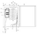
도 1에 도시된 바와 같이, 상기 광케이블 단자함은 전신주나 옥내/외의 벽면에 고정되는 함체(10)를 기본적으로 구비한다.As shown in FIG. 1, the optical cable terminal box basically includes a
상기 함체(10) 측면에는 광케이블(C1)이 끼워지도록 광케이블 인입구(11)가 형성되고, 이 광케이블 인입구(11)의 맞은편에는 최종가입자와 접속되어 있는 광옥외선(C2)이 끼워지는 복수의 광옥외선 인입구(12)가 형성된다.An
또한, 상기 함체(10)의 전면에는 커버(20)가 개폐가능하게 힌지결합되어 있으며, 함체(10)의 배면에는 외측으로 연장형성된 지지편(13)이 형성되고 이 지지편(13)에는 체결공(14)이 형성된다.In addition, the front surface of the
따라서, 상기 광케이블 단자함은 커버(20)가 전면을 향하도록 전신주나 옥내/외의 벽면에 함체(10)를 밀착시킨 상태에서 상기 지지편(13)의 체결공(14)으로 체결볼트를 결합시켜 전신주나 옥내/외의 벽면에 견고하게 고정될 수 있다.Therefore, the optical cable terminal box is a whole body by coupling the fastening bolts to the
한편, 상기 함체(10)의 내부에는 광어댑터 패널(30)이 설치된다. 이 광어댑터 패널(30)에는 광어댑터 입력단자(31a)와 출력단자(31b)가 양측에 각각 구비된 다수의 광어댑터(31)가 설치된다.Meanwhile, an
따라서, 함체(10)를 전신주나 옥내/외의 벽면에 고정시킨 상태에서 상기 광케이블 인입구(11)에 광케이블(C1)을 끼워 함체(10) 내부로 인입시킨 다음, 인입된 광케이블(C1)의 외부피복을 벗겨 다수의 광섬유 클러스터(이하 "광섬유"라 함)로 분기시키고 이를 다시 스플리터(S)를 이용하여 8가닥의 광섬유 단위로 재분기하고, 분기된 각각의 광섬유를 커넥터(32a)를 이용하여 광어댑터 입력단자(31a)에 각각 결합시키면 광케이블(C1)의 연결이 완료된다.Therefore, in the state in which the
이후, 함체(10)에 형성된 광옥외선 인입구(12)에 광옥외선(C2)을 각각 끼운 후 상기 광옥외선(C2)을 커넥터(32b)를 이용하여 광어댑터 출력단자(31b)에 각각 결합시키면 광케이블(C1)과 광옥외선(C2)의 연결작업이 완료된다.Thereafter, the photo-outer rays C2 are inserted into the photo-
이때, 상기 함체(10)의 내부에는 상기 광케이블 인입구(11)를 통해 함체(10) 내부로 인입된 광케이블(C1)이 광섬유들로 분기되어 상기 광섬유들이 광어댑터 입력단자(31a)에 각각 연결되기까지의 과정에서 상기 광섬유들이 엉키지 않도록 하기 위하여 상기 어댑터패널(30)의 일측에 분기된 광섬유들이 지지되는 정리부재(40)가 설치된다.In this case, the optical cable C1 introduced into the
종래의 이러한 광케이블 단자함은 여러개의 광케이블이 연결되어 있는 광어댑터 패널(30)이 상기 함체(10)의 내부에 고정되어 있어서 수리 및 교체 등의 작업이 협소한 공간으로 인해 어려운 문제점이 있다.The conventional optical cable terminal box has a problem that the
본 발명은 전술한 문제를 해결하기 위하여 안출된 것으로, 작업공간이 협소한 한정된 공간인 단자함 내부에서 광 케이블의 접속 및 광 아답타등의 설치 및 광 분배 장치의 설치를 원활하고 쉽게 할 수 있는 광케이블 단자함을 제공하는데 그 목적이 있다.The present invention has been made to solve the above-described problem, an optical cable terminal box that can facilitate the installation of the optical cable and the connection of the optical cable, the installation of the optical adapter, and the installation of the optical distribution unit in the terminal box which is a limited space with a narrow workspace. The purpose is to provide.
전술한 목적을 달성하기 위한 본 발명의 광케이블 단자함은, 단자함 본체와, 상기 단자함 본체에 형성되는 브라켓과, 상기 브라켓에 전후방향으로 슬라이딩가능하게 설치되는 광어댑터 패널을 포함한다.An optical cable terminal box of the present invention for achieving the above object includes a terminal box body, a bracket formed on the terminal box body, and an optical adapter panel slidably installed in the front and rear directions on the bracket.
상기 브라켓에는 가이드홈이 형성되고, 상기 광어댑터 패널에는 상기 가이드홈에 삽입되는 가이드돌기가 형성되며, 상기 가이드홈은 전후방향으로 형성되는 제1가이드홈과 상기 제1가이드부에 연속되게 형성되며 상하방향으로 형성되는 제2가이드홈을 포함할 수 있다.A guide groove is formed in the bracket, and a guide protrusion inserted into the guide groove is formed in the optical adapter panel, and the guide groove is continuously formed in the first guide groove and the first guide portion formed in the front-rear direction. It may include a second guide groove formed in the vertical direction.
이상에서 설명한 바와 같은 본 발명의 광케이블 단자함에 따르면, 다음과 같은 효과가 있다.According to the optical cable terminal box of the present invention as described above, there are the following effects.
단자함 본체에 형성되는 브라켓과, 상기 브라켓에 전후방향으로 슬라이딩가능하게 설치되는 광어댑터 패널을 포함하여, 작업을 넓은 공간에서 할 수 있게 되어 케이블을 광어댑터에 설치하거나 수리하거나 하는 작업이 용이해진다.Including a bracket formed on the terminal box main body and an optical adapter panel slidably installed in the front and rear directions, the operation can be performed in a large space, thereby facilitating the installation or repair of the cable in the optical adapter.
상기 브라켓에는 가이드홈이 형성되고, 상기 광어댑터 패널에는 상기 가이드홈에 삽입되는 가이드돌기가 형성되며, 상기 가이드홈은 전후방향으로 형성되는 제1가이드홈과 상기 제1가이드부에 연속되게 형성되며 상하방향으로 형성되는 제2가이드홈을 포함하여, 간단한 구조로 작업시 광어댑터 패널의 위치가 고정되어 작업자가 더욱 용이하게 작업을 수행할 수 있다.A guide groove is formed in the bracket, and a guide protrusion inserted into the guide groove is formed in the optical adapter panel, and the guide groove is continuously formed in the first guide groove and the first guide portion formed in the front-rear direction. Including a second guide groove formed in the vertical direction, the position of the optical adapter panel is fixed when working with a simple structure, the operator can perform the operation more easily.
도 1은 종래의 광케이블 단자함을 나타내는 정면도.
도 2는 본 발명의 바람직한 실시예에 따른 광케이블 단자함 정면 사시도.
도 3은 본 발명의 바람직한 실시예에 따른 광케이블 단자함 배면 사시도.
도 4는 본 발명의 바람직한 실시예에 따른 광케이블 단자함이 전봇대에 설치된 상태를 나타내는 배면 사시도.
도 5는 본 발명의 바람직한 실시예에 따른 광케이블 단자함이 벽면에 설치된 상태를 나타내는 정면 사시도.
도 6은 본 발명의 바람직한 실시예에 따른 광케이블 단자함 분리 사시도.
도 7은 본 발명의 바람직한 실시예에 따른 광케이블 단자함 볼트 체결부 부분 단면도.
도 8은 본 발명의 바람직한 실시예에 따른 광케이블 단자함 결합 상태 사시도.
도 9는 본 발명의 바람직한 실시예에 따른 광케이블 단자함에 광케이블이 연결된 상태를 보여주는 사시도.
도 10은 본 발명의 바람직한 실시예에 따른 광케이블 단자함 작업시 상태를 보여주는 사시도.1 is a front view showing a conventional optical cable terminal box.
2 is a front perspective view of an optical cable terminal box according to a preferred embodiment of the present invention.
3 is a rear perspective view of an optical cable terminal box according to a preferred embodiment of the present invention.
Figure 4 is a rear perspective view showing a state in which the optical cable terminal box is installed on the power pole according to a preferred embodiment of the present invention.
Figure 5 is a front perspective view showing a state in which the optical cable terminal box is installed on the wall according to a preferred embodiment of the present invention.
6 is an exploded perspective view of an optical cable terminal box according to a preferred embodiment of the present invention.
7 is a partial cross-sectional view of an optical cable terminal box bolt fastening according to a preferred embodiment of the present invention.
Figure 8 is a perspective view of the optical cable terminal box coupled state according to a preferred embodiment of the present invention.
9 is a perspective view showing a state in which the optical cable is connected to the optical cable terminal box according to an embodiment of the present invention.
10 is a perspective view showing a state during operation of the optical cable terminal box according to a preferred embodiment of the present invention.
이하, 본 발명의 바람직한 일실시예를 첨부도면을 참조하여 상세히 설명하면 다음과 같다.Hereinafter, preferred embodiments of the present invention will be described in detail with reference to the accompanying drawings.
참고적으로, 이하에서 설명될 본 발명의 구성들 중 종래기술과 동일한 구성에 대해서는 전술한 종래기술을 참조하기로 하고 별도의 상세한 설명은 생략한다.For reference, the same components as those of the conventional art will be described with reference to the above-described prior art, and a detailed description thereof will be omitted.
도 2 내지 도 10에 도시된 바와 같이, 본 실시예의 광케이블 단자함은, 단자함 본체(100)와, 상기 단자함 본체(100)에 형성되는 브라켓(200)과, 상기 브라켓(200)에 전후방향으로 슬라이딩가능하게 설치되는 광어댑터 패널(300)을 포함한다.As shown in Figure 2 to 10, the optical cable terminal box of the present embodiment, the
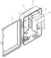
도 2에 도시된 바와 같이, 단자함 본체(100)는 속이 빈 직사각 형상으로 형성되며, 전면에 도어(110)가 설치되어 필요에 따라 전방이 개방될 수 있다.As shown in Figure 2, the
단자함 본체(100)는 전체가 합성수지재로 형성될 수 있다.The
도어(110)는 일측부가 힌지부(160)를 통해 단자함 본체(100)에 연결된다.The
또한, 도어(110)는 타측부에 로킹부(140)가 형성되어 도어(110)는 닫혀진 상태가 유지된다. 이러한 로킹부(140)를 통해 작업자가 필요시에만 단자함 내부를 볼 수 있도록 한다. 로킹부(140)는 볼트 등으로 구비되어 도어(110)의 로킹상태가 견고하게 유지될 수 있도록 한다.In addition, the
나아가, 도어(110)의 타측부에 로킹부(140)의 상부 및 하부에 각각 배치되도록 걸림돌기(150)가 돌출되도록 형성된다.Furthermore, the
걸림돌기(150)는 상부 및 하부에 각각 돌기가 형성되어, 단자함 본체(100)에 형성된 돌출턱(190)에 걸리게 된다.The
이와 같은 걸림돌기(150) 및 돌출턱(190)이 구비되어, 도어(110)의 로킹 작업시 일차적으로 걸림돌기(150)를 돌출턱(190)에 걸리도록 해 놓으면 도어(110)가 전방으로 개방되지 않게 되어 작업이 용이해진다.Such a
단자함 본체(100)의 하부 양측에는 광케이블 등이 인입되거나 인출되는 인입출부(180)가 형성된다.At both sides of the lower side of the terminal box
도 3에 도시된 바와 같이, 본 실시예의 단자함은 단자함 본체(100)의 배면에 회동가능하게 설치되는 고리부(120)를 포함한다.As shown in Figure 3, the terminal box of the present embodiment includes a
고리부(120)는 양측의 수직부와 양측의 수직부를 연결하는 수평부를 포함하여 "U"자 형상으로 형성되며 양단은 회동축(122)에 의해 연결된다.The
상기 수평부는 수직부보다 전후두께가 더 두껍게 형성되어 있다. 이로 인해 고리부(120)의 중량을 최소화할 수 있으며 고리부(120)의 강성되 향상시킬 수 있다.The horizontal portion has a thicker front and rear thickness than the vertical portion. Due to this it is possible to minimize the weight of the
고리부(120)가 접혀져 있을 때 고리부(120) 후방의 표면에는 원호형상으로 굴곡부(121)가 형성된다. 굴곡부(121)는 상기 수평부의 중심부에 형성된다.When the
상기 수평부에는 전후방향으로 삽입공(123)이 여러개 형성된다.The horizontal portion is formed with a plurality of
이러한 삽입공(123)으로 인해 단자함의 무게가 감소될 수 있으며, 단자함을 벽에 설치할 경우 벽에 박혀진 못 등에 용이하게 걸어놓을 수 있게 된다.Due to the
나아가, 단자함 본체(100)의 배면에는 고정밴드(B)가 삽입되는 관통공(131)이 좌우방향으로 형성되는 돌출부(130)가 형성된다.Furthermore, a
돌출부(130)의 후방의 표면 중심부에는 제2굴곡부(132)가 형성된다. 제2굴곡부(132)는 굴곡부(121)와 일직선상에 배치되도록 형성된다.The second
돌출부(130) 양측의 전후두께는 고리부(120)의 수평부의 두께와 유사 또는 동일하도록 형성되어 단자함이 안정적으로 설치될 수 있다.The front and rear thicknesses of both sides of the
돌출부(130)의 하부 양측에는 고리부(120)의 회동축(122)이 삽입되는 축삽입홈(134)이 하부가 개방되도록 형성되고, 상기 축삽입홈(134) 내부에 배치되도록 축걸림돌기(135)가 형성된다.On both sides of the lower portion of the protruding
고리부(120)의 회동축(122)을 돌출부(130) 축삽입홈(134)에 끼워넣으면 돌출부(130) 하부가 탄성변형되면서 축삽입홈(134)의 사이간격이 넓어져 회동축(122)이 축삽입홈(134)에 삽입된다. 이로 인해, 고리부(120)는 돌출부(130)에 회동가능하게 설치된다. 이와 같이 고리부(120)가 설치된 후에는 회동축(122)이 걸림돌기(135)에 의해 걸려서 빠지지 않게 된다.When the pivot shaft 122 of the
이러한 고리부(120) 및 돌출부(130)는 단자함 본체(100)의 배면 상부 및 하부에 각각 배치될 수 있다.The
도 4에 도시된 바와 같이, 이러한 본실시예의 단자함은 전봇대에 설치할 경우에는 고리부(120)를 접은 상태에서 밴드(B)를 관통공(131)에 삽입하고, 굴곡부(121) 및 제2굴곡부(132)가 전봇대의 굴곡진 표면가 맞닿도록 한다. 이로 인해 단자함은 굴곡진 표면을 가진 전봇대에 안정적으로 설치된다.As shown in FIG. 4, the terminal box of the present embodiment inserts the band B into the through
또한, 도 5에 도시된 바와 같이, 이러한 본실시예의 단자함은 평평한 벽면(W)에 설치할 경우에는 고리부(120)를 회동시켜서 고리부(120)를 펼쳐서 벽면에 설치된 못 등에 걸어놓을 수 있다. 이로 인해 단자함은 평평한 표면을 가진 벽면(W)에 안정적으로 설치된다.In addition, as shown in Figure 5, the terminal box of this embodiment, when installed on a flat wall surface (W) can be rotated by the
이와 같이 본 실시예의 단자함은 별다른 조치 없이도 굴곡진 전봇대나 벽면(W)에 필요에 따라 용이하게 설치할 수 있다.Thus, the terminal box of the present embodiment can be easily installed on the curved power pole or the wall (W) as needed without any special measures.
이와 같은 돌출부(130) 및 고리부(120)로 인해 단자함이 전봇대에 설치될 경우 단자함 본체(100)와 전봇대와의 접촉면적이 늘어나서 단자함이 안정적으로 설치된 상태를 유지할 수 있으며, 고리부(130)의 설치도 용이해지고, 평평한 벽면(W)에 고리를 이용하여 설치될 경우에도 벽면(W)과 단자함과의 접촉면적이 늘어나서 단자함이 흔들리지 않고 안정적으로 설치된다.When the terminal box is installed on the power pole due to the protruding
또한, 단자함 본체(100) 배면에는 보조돌기(170)가 형성된다. 보조돌기(170)는 단자함 내부에 설치되는 볼트 위치에 대응되도록 형성될 수 있다. 보조돌기(170) 내부에는 너트(900)가 인서트 사출성형 될 수 있다.In addition, the
너트(900)는 단자함 본체(100)에 의해 외부로 노출되지 않도록 둘러싸여서 부식 등이 방지될 수 있다. 또한, 너트(900)의 외주면에는 원주방향을 따라 홈이 형성되어 있고, 너트(900)의 외주면에는 상하방향으로 길이방향 홈이 형성되어 쉽게 이탈되거나 헛돌지 않게 되는 이점이 있다.The
이러한 보조돌기(170)로 인해 단자함 본체(100)의 중량을 가볍게 유지하면서도 단자함 내부에 부품들을 볼트 등을 통해 견고하게 고정할 수 있다. 나아가, 단자함을 벽면(W)이나 전봇대에 설치할 경우 보조돌기(170)로 인해 접촉면적이 증가하여 단자함이 안정적으로 고정될 수 있다.Due to the
도 6에 도시된 바와 같이, 브라켓(200)은 단자함 본체(100)의 내부에 형성된다. 브라켓(200)은 본 실시예에서와 같이 별도의 부재로 구비되어 단자함 본체(100) 내부에 설치되거나, 이와 다르게 단자함 본체(100) 내부에 일체로 형성될 수 있다.As shown in FIG. 6, the
단자함 본체(100) 내부 일측에는 광섬유 또는 광케이블 등을 정리하는 정리부재(500)가 배치되고, 타측에는 브라켓(200)이 배치된다.On one side of the terminal box
단자함 본체(100) 내부 타측 하부에는 광케이블 등을 가이드하는 가이드고리(600)가 형성된다. 가이드고리(600) 일측에는 절개부가 형성되어 광케이블 등을 용이하게 삽입할 수 있도록 한다.A
브라켓(200)은 단자함 본체(100) 내부에 설치되는 판넬형상의 마운팅판넬(400)에 설치된다. 마운팅판넬(400)은 생략할 수도 있다.The
브라켓(200)은 양측벽과 양측벽을 연결하는 상부벽과 마운팅판넬(400)과 맞닿는 배면을 포함한다.The
브라켓(200)은 양측벽에 각각 가이드홈이 형성된다.The
상기 가이드홈은 전후방향으로 형성되는 제1가이드홈(221)과 제1가이드홈(221)에 연속되게 형성되며 상하방향으로 형성되는 제2가이드홈(222)을 포함한다.The guide groove includes a
상기 가이드홈은 상기 양측벽의 상부와 하부에 각각 형성되고, 상기 양측벽에는 상기 가이드홈의 아래에 보조가이드홈이 형성된다.The guide grooves are formed at upper and lower portions of both side walls, respectively, and auxiliary guide grooves are formed at both side walls of the guide grooves.
상기 보조가이드홈도 전후방향으로 형성되는 제1가이드홈(231)과 제1가이드부(221)에 연속되게 형성되며 상하방향으로 형성되는 제2가이드홈(232)을 포함한다.The auxiliary guide groove also includes a
상기 보조가이드홈의 상부 및 하부에는 지지벽(233)이 형성된다.
상기 상부벽 양측에는 절개부(210)가 전방으로 향할수록 폭이 넓어지도록 형성된다.Both sides of the upper wall are formed to have a wider width as the
광어댑터 패널(300)은 브라켓(200)에 전후방향으로 슬라이딩가능하게 설치된다.The
광어댑터 패널(300)도 양쪽에 배치되는 측벽과 측벽의 전방 상부를 연결하는전방연결부와 측벽의 후방을 연결하는 후방연결부를 포함한다.The
광어댑터 패널(300)의 양쪽의 측벽 내부에는 선반돌출부(340)가 상하방향으로 형성되어 있다.
광어댑터 패널(300)의 일측 측벽의 전방에는 광어댑터(330)가 관통되도록 설치된다. 광어댑터(330)가 설치되는 위치는 상황에 따라 다양하게 변경할 수 있다.The
광어댑터 패널(300)의 측벽 외측 하부에는 타부품이 체결될 수 있는 체결부가 돌출되어 형성된다. 상기 체결부에는 너트가 인서트 사출성형될 수 있다.The fastening part to which other components can be fastened is formed at the lower side of the outer sidewall of the
광어댑터 패널(300)의 일측 측벽의 외측에는 상기 가이드홈에 삽입되는 가이드돌기(310)가 형성된다.A
광어댑터 패널(300)의 일측 측벽의 외측에는 가이드돌기(310)의 하부에 배치되며 상기 보조가이드홈에 삽입되는 보조돌기(320)가 형성된다.An
도 7에 도시된 바와 같이, 보조돌기(320)에는 볼트(700)가 삽입되는 볼트삽입공(321)이 형성된다. 상기 볼트 삽입공(321) 내부에는 스프링(800)이 설치된다.As shown in FIG. 7, the
도 8에 도시된 바와 같이, 단자함 본체(100) 내부에 브라켓(200)을 놓고, 브라켓(200)의 보조가이드홈에 광어댑터 패널(300)의 보조돌기(320)를 삽입한 후에, 도 7에 도시된 바와 같이, 볼트(700)를 볼트삽입공(321)에 삽입한 후에 보조돌기(170)에 설치된 너트(900)에 체결하여 브라켓(200) 및 광어댑터 패널(300)의 조립이 완성된다.As shown in FIG. 8, after placing the
추후 수리나 교체를 위한 작업시 볼트(700)를 조금만 풀어주면 스프링(800)의 탄성력에 의해 볼트(700)가 튀어 나와서 작업이 용이해진다. 이와 같이 스프링(800)을 이용한 구조는 도어(110)의 로킹부(140)에도 동일하게 적용할 수 있다.If the
또한, 브라켓(200)의 상기 상부벽 양측에는 절개부(210)가 형성되어, 브라켓(200)의 양측벽 사이 간격을 용이하게 넓게 할 수 있어서 상기 가이드홈과 상기 보조가이드홈에 가이드돌기(310)와 보조돌기(320)를 각각 용이하게 삽입할 수 있다.In addition,
한편, 도 9에 도시된 바와 같이, 단자함 사용시에는 광어댑터 패널(300)에는 다수의 광케이블이 연결되어 있다. 따라서, 추후 수리나 교체를 위한 작업시에 단자함 본체(100) 내부에는 작업을 위한 공간이 너무 협소해지게 된다.Meanwhile, as shown in FIG. 9, when the terminal box is used, a plurality of optical cables are connected to the
따라서, 본 실시예에서는 추후 수리나 교체를 위한 작업시에는 광어댑터 패널(300)을 단자함 본체(100) 및 브라켓(200)에 대해 전방으로 슬라이딩시킨다. 이로 인해, 작업자는 작업을 넓은 공간에서 할 수 있게 되어 케이블을 광어댑터(330)에 설치하거나 수리하거나 하는 작업이 용이해진다.Therefore, in the present embodiment, the
상세하게는 볼트(700)를 풀어서 광어댑터 패널(300)이 슬라이딩가능한 상태가 되도록 한 다음, 가이드돌기(310) 및 보조돌기(320)를 가이드홈 및 보조가이드홈을 따라 전방으로 슬라이딩시킨 후에 하부로 슬라이딩시켜서 광어댑터 패널(300)이 전방으로 이동된 상태에서 전후방향으로 이동되지 않도록 고정시킨다. 이와 같이 간단한 구조로 작업시 광어댑터 패널(300)의 위치가 고정되어 작업자가 더욱 용이하게 작업을 수행할 수 있다.In detail, the
상술한 바와 같이, 본 발명의 바람직한 실시예를 참조하여 설명하였지만, 해당기술분야의 당업자는 하기의 특허청구범위에 기재된 본 발명의 사상 및 영역으로부터 벗어나지 않는 범위 내에서 본 발명을 다양하게 수정 또는 변형하여 실시할 수 있다.It will be understood by those skilled in the art that various changes in form and details may be made therein without departing from the spirit and scope of the present invention as defined by the following claims .
** 도면의 주요 부분에 대한 부호의 설명 **
100 : 단자함 본체110 : 도어
120 : 고리130 : 돌출부
140 : 로킹부150 : 걸림돌기
160 : 힌지부170 : 보조돌기
180 : 인입출부200 : 브라켓
300 : 광어댑터 패널400 : 마운팅판넬DESCRIPTION OF REFERENCE NUMERALS
100: terminal box body 110: door
120: ring 130: protrusion
140: locking unit 150: locking projection
160: hinge 170: auxiliary protrusion
180: inlet and outlet 200: bracket
300: optical adapter panel 400: mounting panel
Claims (2)
Translated fromKorean상기 단자함 본체에 형성되는 브라켓;
상기 브라켓에 전후방향으로 슬라이딩가능하게 설치되는 광어댑터 패널을 포함하고,
상기 브라켓에는 가이드홈이 형성되고, 상기 광어댑터 패널에는 상기 가이드홈에 삽입되는 가이드돌기가 형성되며,
상기 가이드홈은 전후방향으로 형성되는 제1가이드홈과 상기 제1가이드홈에 연속되게 형성되며 하방향으로 형성되는 제2가이드홈을 포함하며,
상기 광어댑터 패널의 외측에는 보조돌기가 형성되고,
상기 보조돌기에는 볼트가 삽입되는 볼트삽입공이 형성되며,
상기 볼트삽입공 내부에는 스프링이 설치되고,
상기 볼트는 상기 단자함 본체에 형성된 보조돌기에 설치된 너트에 체결되는 광케이블 단자함.A terminal box body;
A bracket formed on the terminal box body;
An optical adapter panel slidably installed in the front and rear directions on the bracket,
A guide groove is formed in the bracket, and a guide protrusion inserted into the guide groove is formed in the optical adapter panel.
The guide groove includes a first guide groove formed in the front and rear direction and a second guide groove formed continuously in the first guide groove and formed in the downward direction.
An auxiliary protrusion is formed on the outside of the optical adapter panel,
The auxiliary protrusion is formed with a bolt insertion hole is inserted into the bolt,
A spring is installed inside the bolt insertion hole,
The bolt is an optical cable terminal box is fastened to a nut installed in the auxiliary projection formed in the terminal box body.
Priority Applications (2)
| Application Number | Priority Date | Filing Date | Title |
|---|---|---|---|
| KR1020120002063AKR101317149B1 (en) | 2012-01-06 | 2012-01-06 | A fiber optic cable connecting terminal box |
| PCT/KR2012/011369WO2013103206A1 (en) | 2012-01-06 | 2012-12-24 | Optical cable terminal box |
Applications Claiming Priority (1)
| Application Number | Priority Date | Filing Date | Title |
|---|---|---|---|
| KR1020120002063AKR101317149B1 (en) | 2012-01-06 | 2012-01-06 | A fiber optic cable connecting terminal box |
Publications (2)
| Publication Number | Publication Date |
|---|---|
| KR20130081087A KR20130081087A (en) | 2013-07-16 |
| KR101317149B1true KR101317149B1 (en) | 2013-10-10 |
Family
ID=48745247
Family Applications (1)
| Application Number | Title | Priority Date | Filing Date |
|---|---|---|---|
| KR1020120002063AActiveKR101317149B1 (en) | 2012-01-06 | 2012-01-06 | A fiber optic cable connecting terminal box |
Country Status (2)
| Country | Link |
|---|---|
| KR (1) | KR101317149B1 (en) |
| WO (1) | WO2013103206A1 (en) |
Cited By (1)
| Publication number | Priority date | Publication date | Assignee | Title |
|---|---|---|---|---|
| KR102217677B1 (en)* | 2020-04-10 | 2021-02-19 | (주)나이스에너지 | Drawer type optical cable terminal box equipped with terraced type optical adaptor panel |
Families Citing this family (27)
| Publication number | Priority date | Publication date | Assignee | Title |
|---|---|---|---|---|
| KR200481500Y1 (en)* | 2014-12-24 | 2016-10-11 | 주식회사 유라코퍼레이션 | connector |
| JP6469154B2 (en)* | 2017-03-21 | 2019-02-13 | 株式会社フジクラ | Connection box |
| US11300746B2 (en) | 2017-06-28 | 2022-04-12 | Corning Research & Development Corporation | Fiber optic port module inserts, assemblies and methods of making the same |
| US10359577B2 (en) | 2017-06-28 | 2019-07-23 | Corning Research & Development Corporation | Multiports and optical connectors with rotationally discrete locking and keying features |
| CN111051945B (en) | 2017-06-28 | 2023-12-29 | 康宁研究与开发公司 | Compact fiber optic connector, cable assembly and method of making the same |
| US11668890B2 (en) | 2017-06-28 | 2023-06-06 | Corning Research & Development Corporation | Multiports and other devices having optical connection ports with securing features and methods of making the same |
| US11187859B2 (en) | 2017-06-28 | 2021-11-30 | Corning Research & Development Corporation | Fiber optic connectors and methods of making the same |
| US12271040B2 (en) | 2017-06-28 | 2025-04-08 | Corning Research & Development Corporation | Fiber optic extender ports, assemblies and methods of making the same |
| US10641967B1 (en) | 2018-11-16 | 2020-05-05 | Corning Research & Development Corporation | Multiport assemblies including a modular adapter support array |
| US10768382B2 (en) | 2018-11-29 | 2020-09-08 | Corning Research & Development Corporation | Multiport assemblies including access apertures and a release tool |
| PT3903136T (en) | 2018-12-28 | 2024-12-05 | Corning Res & Dev Corp | Multiport assemblies including mounting features or dust plugs |
| WO2020242847A1 (en) | 2019-05-31 | 2020-12-03 | Corning Research & Development Corporation | Multiports and other devices having optical connection ports with sliding actuators and methods of making the same |
| US11294133B2 (en) | 2019-07-31 | 2022-04-05 | Corning Research & Development Corporation | Fiber optic networks using multiports and cable assemblies with cable-to-connector orientation |
| US11487073B2 (en) | 2019-09-30 | 2022-11-01 | Corning Research & Development Corporation | Cable input devices having an integrated locking feature and assemblies using the cable input devices |
| EP3805827B1 (en) | 2019-10-07 | 2025-07-30 | Corning Research & Development Corporation | Fiber optic terminals and fiber optic networks having variable ratio couplers |
| US11650388B2 (en) | 2019-11-14 | 2023-05-16 | Corning Research & Development Corporation | Fiber optic networks having a self-supporting optical terminal and methods of installing the optical terminal |
| US11536921B2 (en) | 2020-02-11 | 2022-12-27 | Corning Research & Development Corporation | Fiber optic terminals having one or more loopback assemblies |
| US11604320B2 (en) | 2020-09-30 | 2023-03-14 | Corning Research & Development Corporation | Connector assemblies for telecommunication enclosures |
| CN112327434B (en)* | 2020-10-28 | 2023-04-07 | 国网四川省电力公司南充供电公司 | Optical fiber terminal box |
| AU2021368055A1 (en) | 2020-10-30 | 2023-06-08 | Corning Research & Development Corporation | Female fiber optic connectors having a rocker latch arm and methods of making the same |
| KR200496743Y1 (en) | 2020-11-12 | 2023-04-13 | 주식회사 한국가스기술공사 | Micro position device for terminal box |
| KR102255089B1 (en)* | 2020-11-17 | 2021-05-21 | 구진모 | Residential Node for Optical cable |
| US11686913B2 (en) | 2020-11-30 | 2023-06-27 | Corning Research & Development Corporation | Fiber optic cable assemblies and connector assemblies having a crimp ring and crimp body and methods of fabricating the same |
| US11880076B2 (en) | 2020-11-30 | 2024-01-23 | Corning Research & Development Corporation | Fiber optic adapter assemblies including a conversion housing and a release housing |
| US11994722B2 (en) | 2020-11-30 | 2024-05-28 | Corning Research & Development Corporation | Fiber optic adapter assemblies including an adapter housing and a locking housing |
| US11927810B2 (en) | 2020-11-30 | 2024-03-12 | Corning Research & Development Corporation | Fiber optic adapter assemblies including a conversion housing and a release member |
| US11947167B2 (en) | 2021-05-26 | 2024-04-02 | Corning Research & Development Corporation | Fiber optic terminals and tools and methods for adjusting a split ratio of a fiber optic terminal |
Citations (4)
| Publication number | Priority date | Publication date | Assignee | Title |
|---|---|---|---|---|
| KR200350839Y1 (en)* | 2004-02-10 | 2004-05-17 | 명성네트콤 (주) | Structure for fixation a panel of a optical cable terminal box |
| KR100584843B1 (en) | 2004-02-10 | 2006-05-30 | 명성네트콤 (주) | Optical Cable Branch Distribution Junction |
| US20090148119A1 (en)* | 2007-02-28 | 2009-06-11 | Guy Castonguay | Fiber Optic Drop Terminals for Multiple Dwelling Units |
| KR101214847B1 (en) | 2011-04-13 | 2012-12-24 | 주식회사 유라코퍼레이션 | Connector with slide lever |
Family Cites Families (3)
| Publication number | Priority date | Publication date | Assignee | Title |
|---|---|---|---|---|
| US6621975B2 (en)* | 2001-11-30 | 2003-09-16 | Corning Cable Systems Llc | Distribution terminal for network access point |
| KR20090002595U (en)* | 2007-09-11 | 2009-03-16 | 명성네트콤 (주) | Optical connection distribution |
| KR20100060138A (en)* | 2008-11-27 | 2010-06-07 | (주)모던테크 | Fiber distribution case |
- 2012
- 2012-01-06KRKR1020120002063Apatent/KR101317149B1/enactiveActive
- 2012-12-24WOPCT/KR2012/011369patent/WO2013103206A1/enactiveApplication Filing
Patent Citations (4)
| Publication number | Priority date | Publication date | Assignee | Title |
|---|---|---|---|---|
| KR200350839Y1 (en)* | 2004-02-10 | 2004-05-17 | 명성네트콤 (주) | Structure for fixation a panel of a optical cable terminal box |
| KR100584843B1 (en) | 2004-02-10 | 2006-05-30 | 명성네트콤 (주) | Optical Cable Branch Distribution Junction |
| US20090148119A1 (en)* | 2007-02-28 | 2009-06-11 | Guy Castonguay | Fiber Optic Drop Terminals for Multiple Dwelling Units |
| KR101214847B1 (en) | 2011-04-13 | 2012-12-24 | 주식회사 유라코퍼레이션 | Connector with slide lever |
Cited By (1)
| Publication number | Priority date | Publication date | Assignee | Title |
|---|---|---|---|---|
| KR102217677B1 (en)* | 2020-04-10 | 2021-02-19 | (주)나이스에너지 | Drawer type optical cable terminal box equipped with terraced type optical adaptor panel |
Also Published As
| Publication number | Publication date |
|---|---|
| WO2013103206A1 (en) | 2013-07-11 |
| KR20130081087A (en) | 2013-07-16 |
Similar Documents
| Publication | Publication Date | Title |
|---|---|---|
| KR101317149B1 (en) | A fiber optic cable connecting terminal box | |
| US20230387669A1 (en) | Telecommunications enclosure with a separate mountable hinge | |
| US11402589B2 (en) | Mechanical connection interface for a telecommunications component | |
| KR101406662B1 (en) | Outlet device | |
| US8886005B2 (en) | Adapter retaining systems | |
| US12276842B2 (en) | Optical termination and derivation box | |
| US20200384870A1 (en) | Vehicle charge/discharge device | |
| RU2562958C2 (en) | Front panel for socket | |
| EP1438621A2 (en) | Assembly including an optical fiber socket and an optical fiber plug | |
| KR101285334B1 (en) | A fiber optic cable connecting terminal box | |
| US20160313525A1 (en) | Shelf for communications rack or cabinet | |
| KR101837336B1 (en) | Optical Fiber Cable Accommodated Terminal Box Having Enhanced Tightness | |
| KR20210078064A (en) | OPTICAL CABLE TERMINAL BOX for Mudule | |
| KR101366810B1 (en) | Fiber optic cable connecting terminal box | |
| KR102328829B1 (en) | Optical cable terminal box with stepped type optical adaptor panel | |
| JP4270255B2 (en) | Optical fiber outlet | |
| ZA200302335B (en) | Plugboard. | |
| KR101777272B1 (en) | Fiber optic splice closure | |
| KR102217677B1 (en) | Drawer type optical cable terminal box equipped with terraced type optical adaptor panel | |
| CN210041170U (en) | Novel panel wire arrangement structure | |
| KR100356709B1 (en) | Optical fiber cable distribution housing | |
| US10274690B2 (en) | Enclosure with removable frame | |
| KR200322654Y1 (en) | Fiber distribution frame with a spare cable keeping box | |
| KR20160140081A (en) | Fiber optic splice closure | |
| KR200191132Y1 (en) | Optical fiber cable distribution housing |
Legal Events
| Date | Code | Title | Description |
|---|---|---|---|
| A201 | Request for examination | ||
| PA0109 | Patent application | St.27 status event code:A-0-1-A10-A12-nap-PA0109 | |
| PA0201 | Request for examination | St.27 status event code:A-1-2-D10-D11-exm-PA0201 | |
| PN2301 | Change of applicant | St.27 status event code:A-3-3-R10-R13-asn-PN2301 St.27 status event code:A-3-3-R10-R11-asn-PN2301 | |
| E902 | Notification of reason for refusal | ||
| PE0902 | Notice of grounds for rejection | St.27 status event code:A-1-2-D10-D21-exm-PE0902 | |
| E13-X000 | Pre-grant limitation requested | St.27 status event code:A-2-3-E10-E13-lim-X000 | |
| P11-X000 | Amendment of application requested | St.27 status event code:A-2-2-P10-P11-nap-X000 | |
| P13-X000 | Application amended | St.27 status event code:A-2-2-P10-P13-nap-X000 | |
| E902 | Notification of reason for refusal | ||
| PE0902 | Notice of grounds for rejection | St.27 status event code:A-1-2-D10-D21-exm-PE0902 | |
| P11-X000 | Amendment of application requested | St.27 status event code:A-2-2-P10-P11-nap-X000 | |
| P13-X000 | Application amended | St.27 status event code:A-2-2-P10-P13-nap-X000 | |
| PG1501 | Laying open of application | St.27 status event code:A-1-1-Q10-Q12-nap-PG1501 | |
| E701 | Decision to grant or registration of patent right | ||
| PE0701 | Decision of registration | St.27 status event code:A-1-2-D10-D22-exm-PE0701 | |
| GRNT | Written decision to grant | ||
| PR0701 | Registration of establishment | St.27 status event code:A-2-4-F10-F11-exm-PR0701 | |
| PR1002 | Payment of registration fee | St.27 status event code:A-2-2-U10-U11-oth-PR1002 Fee payment year number:1 | |
| PG1601 | Publication of registration | St.27 status event code:A-4-4-Q10-Q13-nap-PG1601 | |
| PN2301 | Change of applicant | St.27 status event code:A-5-5-R10-R13-asn-PN2301 St.27 status event code:A-5-5-R10-R11-asn-PN2301 | |
| FPAY | Annual fee payment | Payment date:20160810 Year of fee payment:6 | |
| PR1001 | Payment of annual fee | St.27 status event code:A-4-4-U10-U11-oth-PR1001 Fee payment year number:4 | |
| PN2301 | Change of applicant | St.27 status event code:A-5-5-R10-R13-asn-PN2301 St.27 status event code:A-5-5-R10-R11-asn-PN2301 | |
| FPAY | Annual fee payment | Payment date:20190925 Year of fee payment:7 | |
| PR1001 | Payment of annual fee | St.27 status event code:A-4-4-U10-U11-oth-PR1001 Fee payment year number:7 | |
| PN2301 | Change of applicant | St.27 status event code:A-5-5-R10-R13-asn-PN2301 St.27 status event code:A-5-5-R10-R11-asn-PN2301 | |
| R17-X000 | Change to representative recorded | St.27 status event code:A-5-5-R10-R17-oth-X000 | |
| PR1001 | Payment of annual fee | St.27 status event code:A-4-4-U10-U11-oth-PR1001 Fee payment year number:8 | |
| R18-X000 | Changes to party contact information recorded | St.27 status event code:A-5-5-R10-R18-oth-X000 | |
| PN2301 | Change of applicant | St.27 status event code:A-5-5-R10-R13-asn-PN2301 St.27 status event code:A-5-5-R10-R11-asn-PN2301 | |
| PR1001 | Payment of annual fee | St.27 status event code:A-4-4-U10-U11-oth-PR1001 Fee payment year number:9 | |
| PR1001 | Payment of annual fee | St.27 status event code:A-4-4-U10-U11-oth-PR1001 Fee payment year number:10 | |
| PR1001 | Payment of annual fee | St.27 status event code:A-4-4-U10-U11-oth-PR1001 Fee payment year number:11 | |
| PR1001 | Payment of annual fee | St.27 status event code:A-4-4-U10-U11-oth-PR1001 Fee payment year number:12 | |
| PR1001 | Payment of annual fee | St.27 status event code:A-4-4-U10-U11-oth-PR1001 Fee payment year number:13 |