KR101313740B1 - OSMU( One Source Multi Use)-type Stereoscopic Camera and Method of Making Stereoscopic Video Content thereof - Google Patents
OSMU( One Source Multi Use)-type Stereoscopic Camera and Method of Making Stereoscopic Video Content thereofDownload PDFInfo
- Publication number
- KR101313740B1 KR101313740B1KR1020070100904AKR20070100904AKR101313740B1KR 101313740 B1KR101313740 B1KR 101313740B1KR 1020070100904 AKR1020070100904 AKR 1020070100904AKR 20070100904 AKR20070100904 AKR 20070100904AKR 101313740 B1KR101313740 B1KR 101313740B1
- Authority
- KR
- South Korea
- Prior art keywords
- image
- stereo
- parallax
- camera
- display
- Prior art date
- Legal status (The legal status is an assumption and is not a legal conclusion. Google has not performed a legal analysis and makes no representation as to the accuracy of the status listed.)
- Active
Links
Images


Classifications
- H—ELECTRICITY
- H04—ELECTRIC COMMUNICATION TECHNIQUE
- H04N—PICTORIAL COMMUNICATION, e.g. TELEVISION
- H04N13/00—Stereoscopic video systems; Multi-view video systems; Details thereof
- H04N13/20—Image signal generators
- H04N13/204—Image signal generators using stereoscopic image cameras
- H04N13/246—Calibration of cameras
- H—ELECTRICITY
- H04—ELECTRIC COMMUNICATION TECHNIQUE
- H04N—PICTORIAL COMMUNICATION, e.g. TELEVISION
- H04N23/00—Cameras or camera modules comprising electronic image sensors; Control thereof
- H04N23/60—Control of cameras or camera modules
- H04N23/67—Focus control based on electronic image sensor signals
- H—ELECTRICITY
- H04—ELECTRIC COMMUNICATION TECHNIQUE
- H04N—PICTORIAL COMMUNICATION, e.g. TELEVISION
- H04N13/00—Stereoscopic video systems; Multi-view video systems; Details thereof
- H04N13/20—Image signal generators
- H04N13/204—Image signal generators using stereoscopic image cameras
- H04N13/239—Image signal generators using stereoscopic image cameras using two 2D image sensors having a relative position equal to or related to the interocular distance
- H—ELECTRICITY
- H04—ELECTRIC COMMUNICATION TECHNIQUE
- H04N—PICTORIAL COMMUNICATION, e.g. TELEVISION
- H04N13/00—Stereoscopic video systems; Multi-view video systems; Details thereof
- H04N13/20—Image signal generators
- H04N13/296—Synchronisation thereof; Control thereof
- H—ELECTRICITY
- H04—ELECTRIC COMMUNICATION TECHNIQUE
- H04N—PICTORIAL COMMUNICATION, e.g. TELEVISION
- H04N13/00—Stereoscopic video systems; Multi-view video systems; Details thereof
- H04N13/10—Processing, recording or transmission of stereoscopic or multi-view image signals
- H04N13/106—Processing image signals
- H04N13/144—Processing image signals for flicker reduction
- H—ELECTRICITY
- H04—ELECTRIC COMMUNICATION TECHNIQUE
- H04N—PICTORIAL COMMUNICATION, e.g. TELEVISION
- H04N13/00—Stereoscopic video systems; Multi-view video systems; Details thereof
- H04N2013/0074—Stereoscopic image analysis
- H04N2013/0081—Depth or disparity estimation from stereoscopic image signals
- H—ELECTRICITY
- H04—ELECTRIC COMMUNICATION TECHNIQUE
- H04N—PICTORIAL COMMUNICATION, e.g. TELEVISION
- H04N2213/00—Details of stereoscopic systems
- H04N2213/002—Eyestrain reduction by processing stereoscopic signals or controlling stereoscopic devices
Landscapes
- Engineering & Computer Science (AREA)
- Multimedia (AREA)
- Signal Processing (AREA)
- Testing, Inspecting, Measuring Of Stereoscopic Televisions And Televisions (AREA)
- Stereoscopic And Panoramic Photography (AREA)
- Cameras In General (AREA)
Abstract
Translated fromKorean
Description
Translated fromKorean본 발명은 원소스 멀티유즈 스테레오 카메라 및 스테레오 영상 컨텐츠 제작방법에 관한 것으로 특히 한번 제작한 입체영상 컨텐츠를 다양한 사이즈의 스테레오 디스플레이들, 휴대폰과 같은 이동단말기기의 디스플레이, 데스크 탑 컴퓨터의 디스플레이, 디지털 텔레비젼, 대형 스크린 등에서 디스플레이하여 보더라도 눈에 피로감이 없이 입체 영상을 즐길 수 있는 스테레오 카메라 및 그 스테레오 영상 컨텐츠 제작방법에 관한 것이다.The present invention relates to a OneS multi-use stereo camera and a method for producing stereo image contents. In particular, the stereoscopic image contents produced once are stereo displays of various sizes, displays of mobile terminal devices such as mobile phones, displays of desktop computers, digital television, The present invention relates to a stereo camera that can enjoy stereoscopic images without eye fatigue even when displayed on a large screen and the like and a method for producing stereo image contents thereof.
스테레오 영상(stereoscopic video)은 시차(parallax)를 가진 좌우 이미지들을 합성하여 형성된다. 스크린 상에 디스플레이되는 스테레오 영상에서 제로시차를 가진 물체 상에 비교하여 네가티브 시차를 가진 물체 상은 스크린 앞으로 돌출되어 보이고 포지티브 시차를 가진 물체 상은 스크린 뒤로 후퇴되어 보인다.Stereoscopic video is formed by synthesizing left and right images with parallax. In a stereo image displayed on a screen, an object image having a negative parallax protrudes in front of the screen and a object image having a positive parallax is retracted behind the screen as compared to an object having zero parallax.
실제 눈의 초점조절은 스크린에 맞추어져 있는 데 눈의 수렴과정은 물체 상의 시차에 따라 달라지게 되어 물체 상은 스크린 보다 앞 또는 뒤에 위치한 것으로 지각하게 되므로 눈의 융합 범위를 벗어난 시차가 존재하게 되면 눈의 피로감을 느끼거나 어지러움 등의 두통을 느끼게 되며, 영상의 자연스러움이나 현장감을 떨어지게 하고, 심하면 융합을 못하고 이중상으로 보이게 된다.The actual eye focusing is on the screen. The convergence process of the eye depends on the parallax on the object and the object on the object is perceived as being located in front of or behind the screen. You will feel tiredness or dizziness, headaches, deterioration of the naturalness or realism of the image, and if it is severe, you will not be able to fuse.
스테레오 영상의 시차는 좌우 카메라 사이의 간격과 렌즈와 피사체 사이의 거리에 좌우된다.The parallax of the stereo image depends on the distance between the left and right cameras and the distance between the lens and the subject.
현재 스테레오 영상은 디스플레이되는 환경을 고려하여 스테레오 카메라로 제작된다. 따라서 주시거리가 10m이상의 대형 극장용으로 제작된 스테레오 영상은 주시거리 1m 이내인 컴퓨터나 휴대폰과 같은 이동통신 단말기기의 소형 사이즈의 디스플레이에서는 적합하지 못한 실정이다. 반대로 컴퓨터나 휴대폰 환경을 고려하여 제작된 스테레오 영상은 대형 극장에서는 디스플레이할 수 없게 된다. 즉 지금까지는 원소스 원유스 용도로만 제작되므로 컨텐츠의 유통이 제한적이고 입체영상분양의 다양한 컨텐츠 사업이 활성화되지 못하고 있는 실정이다.Currently, stereo images are produced with a stereo camera in consideration of the displayed environment. Therefore, the stereo image produced for a large theater with a viewing distance of 10m or more is not suitable for a small size display of a mobile communication terminal such as a computer or a mobile phone with a viewing distance of 1m or less. On the contrary, stereo images produced in consideration of computer or mobile phone environments cannot be displayed in large theaters. In other words, until now, only one element's original use is used, so the distribution of contents is limited and various contents business of 3D image distribution is not activated.
최근에는 LCD 및 PDP와 같은 평판 디스플레이 장치의 화면 사이즈가 50인치 이상으로 대형화가 진행되고 있지만 화면 사이즈가 너무 커지면 표시면상의 좌우상 간격이 크게 퍼지는 피사체에서 시차가 융합한계를 초과하는 것은 자연시 상태에서도 생기지만 자연시에 비해 입체화상에서는 눈에 띄기 쉽고 입체화상을 보기 나쁘게 한다. 따라서 촬상시에 표시 화면 사이즈를 고려하지 않을 수 없다.Recently, the screen size of flat panel display devices such as LCDs and PDPs has been enlarged to 50 inches or more. However, when the screen size becomes too large, it is natural that the parallax exceeds the limit of convergence in a subject in which the left and right intervals on the display surface are greatly spread. Although it occurs in, it is more noticeable in three-dimensional images than in natural time and makes three-dimensional images look worse. Therefore, the display screen size must be taken into consideration at the time of imaging.
그러나 지금까지 2인치의 소형 디스플레이에서부터 극장용 대형 스크린까지 원소스 멀티유즈 타입의 스테레오 영상이 제대로 제작된 적이 없었다.However, until now, the Ones multiuse type stereo image has not been produced properly, from the small 2-inch display to the large screen for the theater.
본 발명의 목적은 이와 같은 종래 기술의 문제점을 해결하기 위하여 시청거리 또는 스크린의 사이즈에 관계없이 눈의 피로감이 없이 자연스러운 입체감을 줄 수 있는 입체영상을 제공할 수 있는 스테레오 카메라를 제공하는 데 있다.An object of the present invention is to provide a stereo camera that can provide a three-dimensional image that can give a natural three-dimensional feeling without eye fatigue, regardless of the viewing distance or the size of the screen to solve the problems of the prior art.
또한 본 발명의 다른 목적은 이와 같은 스테레오 카메라를 사용하여 원소스 멀티유즈 타입의 스테레오 영상 컨텐츠를 제작하는 방법을 제공하는 데 있다.In addition, another object of the present invention to provide a method for producing stereo image content of the Elements multi-use using such a stereo camera.
상기 목적을 달성하기 위하여 본 발명의 제1실시예의 스테레오 카메라는 렌즈 광축이 서로 평행하게 배치된 좌측 및 우측 카메라들과, 좌우측 카메라들의 간격을 조절하기 위한 간격조절부와, 임의의 값으로 평행 광축 사이의 간격이 세팅된 스테레오 카메라의 초점을 피사체에 맞추고, 피사체에 초점이 맞추어진 이미지 상의 원점(Far Point) 을 결정하여 중간 사이즈를 가진 스테레오 디스플레이의 원점 제한시차로 이미지의 원점에서의 최대 허용 가능한 한계시차를 산출하는 한계시차 산출부와, 산출된 한계 시차에 의해 평행 광축 사이의 간격 값을 산출하고, 산출된 간격 값에 응답하여 간격 조절부를 구동하는 카메라 간격 산출부와, 카메라 간격 산출부에 의해 간격이 재조정된 좌우측 카메라에 의해 촬상된 좌측 영상 및 우측 영상을 저장하는 영상 저장부를 포함한다.In order to achieve the above object, the stereo camera according to the first embodiment of the present invention includes a left and right cameras in which lens optical axes are arranged in parallel with each other, a gap adjusting unit for adjusting the distance between the left and right cameras, and a parallel optical axis at an arbitrary value. Focus the stereo camera with the distance between the subjects, determine the Far Point on the image focused on the subject, and set the maximum permissible point at the origin of the image with the origin limitation of the medium sized stereo display. A marginal time difference calculator for calculating a marginal parallax, a camera distance calculator that calculates a gap value between parallel optical axes based on the calculated marginal time difference, and drives a gap controller in response to the calculated gap value, and a camera gap calculator Image storing the left image and the right image captured by the left and right cameras whose intervals are readjusted And a storage unit.
본 발명의 원소스 멀티유즈 스테레오 영상은 임의의 값으로 평행 광축 사이의 간격이 세팅된 스테레오 카메라의 초점을 피사체에 맞추고, 피사체에 초점이 맞 추어진 이미지 상의 원점을 결정하고, 중간 사이즈를 가진 스테레오 디스플레이의 원점 제한시차로 이미지의 원점에서의 최대 허용 가능한 한계시차를 산출하고, 산출된 한계시차에 의해 상기 평행 광축 사이의 간격을 재조정하여, 재조정된 스테레오 카메라로 피사체를 촬영하는 것을 특징으로 한다.The element's multi-use stereo image according to the present invention focuses a stereo camera on which a distance between parallel optical axes is set to a subject, determines an origin on an image focused on a subject, and displays a stereo display having a medium size. The maximum permissible marginal parallax at the origin of the image is calculated by the origin limited parallax of the image, the interval between the parallel optical axes is readjusted by the calculated marginal parallax, and the subject is photographed with the readjusted stereo camera.
본 발명에서 중간 사이즈는 가장 보편적으로 널리 보급되거나 될 가능성이 높은 17인치 내지 24인치 범위 내의 데스크 탑 모니터 중 어느 하나를 기준으로 하는 것이 바람직하다. 중간 사이즈를 가진 스테레오 디스플레이의 원점 제한시차는 디스플레이 최적 주시거리의 약 2.79%로 한다. 2.79%는 입체영상에 훈련되지 않은 일반적인 사람들이 융합할 수 있는 최대 각도인 약 1.6도에 대응한다.In the present invention, the medium size is preferably based on any one of the desktop monitors within the range of 17 inches to 24 inches, which are most widely spread or are likely to become widespread. The mid-sized stereo display's origin limitation parallax is about 2.79% of the display's optimal viewing distance. 2.79% corresponds to approximately 1.6 degrees, the maximum angle that can be fused by ordinary people who are not trained in stereoscopic imaging.
본 발명의 제2실시예의 스테레오 카메라는 렌즈 광축이 서로 평행하게 배치된 좌측 및 우측 카메라들과, 좌우측 카메라들의 이미지 센서들 사이의 간격을 조절하기 위한 센서간격 조절부와, 임의의 값으로 상기 이미지 센서들 사이의 간격이 세팅된 스테레오 카메라의 초점을 피사체에 맞추고, 상기 피사체에 초점이 맞추어진 이미지 상의 원점(Far Point) 을 결정하여 중간 사이즈를 가진 스테레오 디스플레이의 원점 제한시차로 상기 이미지의 원점에서의 최대 허용 가능한 한계시차를 산출하는 한계시차 산출부와, 산출된 한계 시차에 의해 상기 이미지 센서들 사이의 간격 값을 산출하고, 산출된 간격 값에 응답하여 상기 센서간격 조절부를 구동하는 카메라 간격 산출부와, 카메라 간격 산출부에 의해 센서간격이 재조정된 좌우측 카메라에 의해 촬상된 좌측 영상 및 우측 영상을 저장하는 영상 저장부를 포함한다.The stereo camera of the second embodiment of the present invention includes left and right cameras in which lens optical axes are disposed in parallel with each other, a sensor gap adjusting unit for adjusting a distance between image sensors of left and right cameras, and the image at an arbitrary value. Focus the stereo camera with the distance between the sensors to the subject, determine the Far point on the image focused on the subject, and set the origin point of the image with the origin limited parallax of the medium sized stereo display. A marginal disparity calculator for calculating a maximum allowable marginal disparity of the camera; and calculating a gap value between the image sensors based on the calculated marginal disparity, and calculating a camera interval for driving the sensor gap controller in response to the calculated gap value. And the left and right cameras whose sensor intervals are readjusted by the camera interval calculator. An image storage unit stores a left image and a right image.
본 발명의 제2실시예의 스테레오 영상 제작방법은 임의의 값으로 평행 광축 을 가진 좌우 이미지센서들 간격이 세팅된 스테레오 카메라의 초점을 피사체에 맞추는 단계와, 피사체에 초점이 맞추어진 이미지 상의 원점을 결정하는 단계와, 중간 사이즈를 가진 스테레오 디스플레이의 원점 제한시차로 상기 이미지의 원점에서의 최대 허용 가능한 한계시차를 산출하는 단계와, 산출된 한계시차에 의해 상기 좌우 이미지센서들 사이의 간격을 재조정하는 단계와, 재조정된 스테레오 카메라로 상기 피사체를 촬영하는 단계를 포함한다.The stereo image production method according to the second embodiment of the present invention comprises the steps of focusing a stereo camera having a distance between the left and right image sensors having a parallel optical axis at an arbitrary value on a subject, and determining an origin on an image focused on the subject. Calculating a maximum allowable marginal parallax at the origin of the image by the origin limiting parallax of the stereo display having a medium size, and adjusting the distance between the left and right image sensors by the calculated limiting parallax; And photographing the subject with a readjusted stereo camera.
본 발명의 제3실시예는 렌즈 광축이 서로 평행하게 고정 배치되고 표시하고자 하는 영상 사이즈 보다 더 큰 광역촬상면적을 가진 이미지 센서와 광역렌즈를 가진 좌측 및 우측 카메라들과, 고정된 간격의 스테레오 카메라의 초점을 피사체에 맞추고, 피사체에 초점이 맞추어진 이미지 상의 원점(Far Point)을 결정하여 중간 사이즈를 가진 스테레오 디스플레이의 원점 제한시차로 이미지의 원점에서의 최대 허용 가능한 한계시차를 산출하는 한계시차 산출부와, 산출된 한계 시차에 의해 상기 평행 광축 사이의 간격 값을 산출하는 카메라 간격 산출부와, 좌우측 카메라들로부터 픽업된 광역 좌우 영상들을 기입하고 독출시에는 카메라 간격 산출부에 의해 산출된 간격값에 응답하여 좌우 표시영상을 출력하는 영상 저장부를 구비한 것을 특징으로 한다.The third embodiment of the present invention is an image sensor having a wide optical imaging area larger than the image size to be fixedly arranged in parallel with each other and the left and right cameras having a wide-area lens, and a fixed interval stereo camera. Calculate the marginal margin that calculates the maximum allowable marginal lag at the origin of the image with the origin limitation of the medium-sized stereo display by focusing on the subject and determining the Far Point on the image focused on the subject. And a camera interval calculator for calculating an interval value between the parallel optical axes by the calculated marginal parallax, and a gap value calculated by the camera interval calculator when writing and reading wide-area left and right images picked up from left and right cameras. And an image storage unit configured to output left and right display images in response to the response.
또한 본 발명의 제3실시예의 콘텐츠 제작방법은 광역촬상면적을 가진 이미지 센서와 광역렌즈를 가지며 고정된 간격으로 세팅된 스테레오 카메라로 피사체를 촬상하고, 촬상된 광역촬상면적의 좌우 영상을 저장하고, 피사체에 초점이 맞추어진 이미지 상의 원점을 결정하고, 중간 사이즈를 가진 스테레오 디스플레이의 원점 제 한시차로 이미지의 원점에서의 최대 허용 가능한 한계시차를 산출하고, 산출된 한계시차에 의해 저장된 광역촬상면적의 영상으로부터 독출하고자 하는 표시영상 독출 어드레스를 재설정하고, 재설정된 독출 어드레스에 응답하여 좌우 표시영상을 독출한다.In addition, the content production method according to the third embodiment of the present invention captures a subject with a stereo camera set at fixed intervals with an image sensor having a wide image area and a wide lens, and stores left and right images of the captured wide area. Determine the origin on the image focused on the subject, calculate the maximum allowable marginal parallax at the origin of the image with the origin limitation of the medium-sized stereo display, and image the wide-area image area stored by the calculated marginal parallax. The display image read address to be read from is reset, and the left and right display images are read in response to the reset read address.
본 발명의 제4실시예는 렌즈 광축이 서로 평행하게 고정 배치되고 표시 영상 사이즈 보다 더 큰 광역촬상면적을 가진 이미지 센서와 광역렌즈를 가진 좌측 및 우측 카메라들과, 고정된 간격의 스테레오 카메라의 초점을 피사체에 맞추고, 상기 피사체에 초점이 맞추어진 이미지 상의 원점(Far Point)을 결정하여 중간 사이즈를 가진 스테레오 디스플레이의 원점 제한시차로 상기 이미지의 원점에서의 최대 허용 가능한 한계시차를 산출하는 한계시차 산출부와, 산출된 한계 시차에 의해 상기 평행 광축 사이의 간격 값을 산출하는 카메라 간격 산출부와, 좌우측 카메라들로부터 픽업된 광역 좌우 영상들 중 카메라 간격 산출부에 의해 산출된 간격값에 응답하여 표시사이즈의 좌우 영상들만을 기입하는 영상 저장부를 구비한 것을 특징으로 한다.The fourth embodiment of the present invention focuses on the left and right cameras having a wide-area lens and an image sensor having a wide-area image area where the lens optical axes are fixedly arranged in parallel with each other and larger than the display image size, and the stereo cameras having fixed intervals. To calculate the maximum allowable marginal disparity at the origin of the image as the origin limiting parallax of the stereo display having a medium size by determining the origin of the image on which the subject is focused. And a camera interval calculating unit for calculating a gap value between the parallel optical axes by the calculated marginal parallax, and displaying in response to the interval value calculated by the camera gap calculating unit among wide-area left and right images picked up from the left and right cameras. And an image storage unit for writing only left and right images of a size.
본 발명의 제4 실시예의 콘텐츠 제작방법은 광역촬상면적을 가진 이미지 센서와 광역렌즈를 가지며 고정된 간격으로 세팅된 스테레오 카메라로 피사체를 촬상하고, 촬상된 피사체에 초점이 맞추어진 이미지 상의 원점을 결정하고, 중간 사이즈를 가진 스테레오 디스플레이의 원점 제한시차로 이미지의 원점에서의 최대 허용 가능한 한계시차를 산출하고, 산출된 한계시차에 의해 카메라 간격값을 산출하여, 산출된 카메라 간격 값에 응답하여 광역촬상면적의 영상으로부터 표시 사이즈의 좌 우영상들만을 저장한다.The content production method of the fourth embodiment of the present invention captures a subject with a stereo camera set at fixed intervals with an image sensor having a wide image area and a wide lens, and determines an origin on an image focused on the captured subject. The maximum permissible marginal parallax at the origin of the image is calculated by the origin limiting parallax of the stereo display having a medium size, and the camera interval value is calculated by the calculated marginal parallax, and in response to the calculated camera interval value Only the left and right images of the display size are stored from the image of the area.
본 발명의 제5실시예는 렌즈 광축이 서로 평행하게 고정 배치되고 표시하고자 하는 영상 사이즈 보다 더 큰 광역촬상면적을 가진 이미지 센서과 광역렌즈를 가진 좌측 및 우측 카메라들과, 고정된 간격의 스테레오 카메라의 초점을 피사체에 맞추고, 상기 피사체에 초점이 맞추어진 이미지 상의 원점(Far Point)을 결정하여 중간 사이즈를 가진 스테레오 디스플레이의 원점 제한시차로 상기 이미지의 원점에서의 최대 허용 가능한 한계시차를 산출하는 한계시차 산출부와, 산출된 한계 시차에 의해 상기 평행 광축 사이의 간격 값을 산출하는 카메라 간격 산출부와, 좌우측 카메라들로부터 픽업된 광역 좌우 영상들을 저장하는 영상 저장부를 구비하고, 좌우측 카메라들의 각 이미지 센서들은 산출된 카메라 간격값에 응답하여 표시 사이즈의 픽셀데이터만을 출력한다.The fifth embodiment of the present invention is to provide an image sensor having a wider imaging area larger than the image size to be fixedly arranged parallel to each other and left and right cameras having a wider lens, and a stereo camera having a fixed interval. A marginal parallax for focusing on a subject, determining a far point on an image focused on the subject, and calculating a maximum allowable marginal disparity at the origin of the image as an origin limited parallax of a stereo display having a medium size. A calculation unit, a camera interval calculation unit for calculating an interval value between the parallel optical axes by the calculated marginal parallax, and an image storage unit for storing wide-area left and right images picked up from the left and right cameras, and each image sensor of the left and right cameras. Only display pixel data of the display size in response to the calculated camera interval value. .
본 발명의 제5실시예의 콘텐츠 제작방법은 광역촬상면적을 가진 이미지 센서와 광역렌즈를 가지며 고정된 간격으로 세팅된 스테레오 카메라로 피사체를 촬상하고, 촬상된 피사체에 초점이 맞추어진 이미지 상의 원점을 결정하고, 중간 사이즈를 가진 스테레오 디스플레이의 원점 제한시차로 상기 이미지의 원점에서의 최대 허용 가능한 한계시차를 산출하고, 산출된 한계시차에 의해 상기 카메라 간격값을 산출하고, 산출된 카메라 간격값에 응답하여 상기 이미지 센서로부터 표시 사이즈의 픽셀 데이터만을 출력하고, 출력된 표시사이즈의 픽셀 데이터를 저장한다.The content production method of the fifth embodiment of the present invention captures a subject with a stereo camera set at fixed intervals with an image sensor having a wide image area and a wide lens, and determines an origin point on an image focused on the captured subject. Calculate a maximum allowable marginal parallax at the origin of the image by the origin limiting parallax of the stereo display having a medium size, calculate the camera interval value by the calculated marginal parallax, and respond to the calculated camera interval value Only the pixel data of the display size is output from the image sensor, and the pixel data of the output display size is stored.
상술한 바와 같이 본 발명에서는 소형 사이즈의 이동통신단말기기의 디스플 레이와 대형 극장 스크린 사이의 가장 보편적이고 널리 보급된 데스크 탑 모니터의 원점 시차를 기준으로 하여 스테레오 카메라의 카메라 간격을 재조정하여 스테레오 영상을 촬영함으로써 원소스 멀티유즈 스테레오 영상 컨텐츠를 제작할 수 있다.As described above, in the present invention, the stereo image is readjusted by adjusting the camera interval of the stereo camera based on the origin parallax of the most common and widely used desktop monitor between the display of the small size mobile communication terminal device and the large theater screen. By shooting the ONES multi-use stereo image content can be produced.
이하, 첨부한 도면을 참조하여 본 발명의 바람직한 실시예를 구체적으로 설명하고자 한다. 이 실시예는 이 기술에 숙련된 자들이 본 발명을 실시할 수 있게 충분히 상세하게 기술한다.Hereinafter, exemplary embodiments of the present invention will be described in detail with reference to the accompanying drawings. This embodiment is described in sufficient detail to enable those skilled in the art to practice the invention.
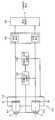
도 1은 본 발명에 의한 원소스 멀티유즈 스테레오 카메라의 바람직한 제1실시예의 블록도를 나타낸다. 도 1을 참조하면, 스테레오 카메라(100)는 카메라부(110), 한계시차 산출부(120), 카메라 간격 산출부(130), 영상 저장부(140), 영상 결합부(150)를 포함한다.Figure 1 shows a block diagram of a first preferred embodiment of an elemental multiuse stereo camera according to the present invention. Referring to FIG. 1, the stereo camera 100 includes a
카메라부(110)는 좌측 카메라(112), 우측 카메라(114), 간격 조절부(116)를 포함한다. 좌우측 카메라들(112, 114)은 간격조절부(116) 상에 서로 평행하게 설치되어 광축에 대해 수직 방향, 즉 좌우 방향으로 이동 가능하여 이들 사이의 간격이 조절 가능하다. 좌측 카메라(112)는 동일 광축 상에 배열된 렌즈(LL)와 이미지 센서(SL)를 포함한다. 우측 카메라(112)는 동일 광축 상에 배열된 렌즈(LR)와 이미지 센서(SR)를 포함한다. 여기서 이미지 센서들(SL,SR)은 CCD 센서 또는 CMOS 센서일 수 있다.The
한계시차 산출부(120)는 임의의 값으로 평행 광축 사이의 간격이 세팅된 스테레오 카메라의 초점을 피사체에 맞추고, 상기 피사체에 초점이 맞추어진 이미지 상의 원점(Far Point) 을 결정하여 중간 사이즈를 가진 스테레오 디스플레이의 원점 제한시차로 상기 이미지의 원점에서의 최대 허용 가능한 한계시차를 결정한다.The marginal
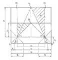
도 2는 스테레오 디스플레이의 원점 제한시차와 스테레오 카메라의 한계시차의 관계를 설명하기 위한 도면이다.FIG. 2 is a diagram for describing a relationship between the origin limited parallax of a stereo display and the limited parallax of a stereo camera.
도 2를 참조하면, 본 발명에서 스테레오 디스플레이의 스크린(160)의 원점 제한시차(PD)는 주시거리(ZV) 의 tan(1.6)의 값으로 산출된다. 통상적으로 입체영상에 훈련되지 않은 일반 사람들에서 융합이 가능한 최대 각도는 약 1.6도라 알려져 있다. 이는 실제 스크린에서 획득되는 망막시차 최대량의 약1/2이다. 그러므로 망막시차의 약 1/2범위 이내로 스크린 시차를 제한함으로써 입체영상을 장시간 보더라도 눈의 피로감을 적고, 두통 등의 현상을 감소시킬 수 있다.Referring to FIG. 2, in the present invention, the origin limited parallax PD of the
다음 표1은 주시거리에 따른 제한시차를 나타낸다.Table 1 below shows the limited parallax according to the viewing distance.
[표1] 스테레오 디스플레이의 원점 제한시차[Table 1] Origin limit parallax in stereo display

본 발명에서는 모든 사이즈의 스테레오 디스플레이에서 하나의 스테레오 영상 컨텐츠를 즐기기 위하여 중간 사이즈 디스플레이 17" 내지 24"의 중형 데스크탑 모니터를 기준으로 원점 제한시차를 사용한다.In the present invention, in order to enjoy one stereo image content in a stereo display of all sizes, the origin limited parallax is used based on the medium size desktop monitor of the medium size display 17 "to 24".
표2에 나타난바와 같이 중형 데스크 탑 모니터는 사용자가 화면 사이즈에 비해 가장 근접된 주시거리에서 바라보게 되기 때문에 가장 큰 화각(FOV: Field Of View) 범위를 갖게 되므로 입체영상 조건에서 가장 악조건을 형성하게 된다.As shown in Table 2, the medium-sized desktop monitor has the largest field of view (FOV) range because the user is looking at the closest viewing distance compared to the screen size, thus forming the worst condition in the stereoscopic conditions. do.
[표2] 디스플레이 크기에 따른 화각[Table 2] View angle according to display size

표1에 표시한 바와 같이 19"를 사용할 경우 표준 주시거리는 46cm로 정하고 원점 제한시차(PD)는 다음 수학식1에 의해 산출한다.As shown in Table 1, when using 19 ", the standard viewing distance is set to 46cm and the origin limit parallax PD is calculated by the following equation (1).
[수학식1][Equation 1]
PD= 0.46(m) × 0.0279 = 0.0128(m)PD = 0.46 (m) × 0.0279 = 0.0128 (m)
24" 디스플레이에 표준 주시거리를 50cm로 하면 제한시차는 0.0140(m)으로 산출된다.If the standard viewing distance is 50cm on a 24 "display, the limit parallax is calculated to be 0.0140 (m).
따라서 스테레오 카메라의 허용 가능한 한계시차(최악의 디스플레이 시청조건하에서의 한계시차)는 다음 수학식2에 의해 산출한다.Therefore, the allowable marginal parallax (limit parallax under the worst display viewing condition) of the stereo camera is calculated by the following equation.
[수학식2]&Quot; (2) "
PS = PD × (WS/WD)PS = PD × (WS / WD )
여기서 PS는 이미지 센서의 원점에서 한계시차, WS는 이미지 센서의 가로 폭, PD는 중간 사이즈의 디스플레이의 원점 제한시차, WD는 디스플레이의 가로 폭이다.Where PS is the marginal parallax at the origin of the image sensor, WS is the horizontal width of the image sensor, PD is the home limited parallax of the medium sized display, and WD is the horizontal width of the display.
예컨대 19" 모니터의 가로 폭(WD)은 0.378m이고 2/3" CCD 이미지 센서의 가로 폭(WS)은 0.0088m이므로 수학식2에 의해 한계시차 PS = 0.0128(m) × (0.0088(m)/0.378(m)) = 0.298(mm)의 값을 가진다.For example, since the width of the 19 "monitor (WD ) is 0.378m and the width of the 2/3" CCD image sensor (WS ) is 0.0088m, the limit parallax PS = 0.0128 (m) × (0.0088) (m) /0.378 (m)) = 0.298 (mm).
카메라 간격 산출부(130)는 산출된 한계시차(PS)에 의해 평행 광축 사이의 간격 값을 다음 수학식 3에 의해 산출하고, 산출된 간격 값에 응답하여 간격 조절부(16)를 구동하여 좌우 카메라의 간격(Cc)을 조정한다.The camera
[수학식3]&Quot; (3) "
Cc = PS/ZS( 1/Z0- 1/ZF)Cc = PS / ZS (1 / Z0-1 / ZF )
그러므로 수학식3에 의하면 최악의 디스플레이 시청조건에서의 한계시차(PS)를 특정화하여 카메라 간격을 조정하므로 원소스 멀티유즈 조건을 만족할 수 있다.Therefore, according to Equation 3, the distance between the cameras is adjusted by specifying the limit parallax PS in the worst display viewing condition, thereby satisfying the elements multiuse condition.
도 3은 카메라부(110)의 좌우 카메라(112, 114)와 피사체 사이의 광학적 기하관계를 나타낸다.3 illustrates an optical geometric relationship between the left and
도 3에서 각 기호는 아래와 같다.In FIG. 3, each symbol is as follows.
AXL: 좌측 렌즈의 광축AXL : Optical axis of the left lens
AXR : 우측 렌즈의 광축AXR : Optical axis of the right lens
Z0: 렌즈 중심으로부터 주시점(OZ)까지의 직선 거리(제로시차거리)Z0 : Linear distance (zero parallax distance) from the lens center to the gaze point (OZ )
ZF: 렌즈 중심으로부터 원점(OF)까지의 직선 거리(시차한계점거리)ZF : Linear distance from the lens center to the origin (OF ) (disparity limit distance)
ZS: 렌즈 중심으로부터 이미지 센서(SL,SR)까지의 직선 거리(상거리)ZS : Straight line distance from the lens center to the image sensors SL and SR
f : 렌즈 촛점거리f: Lens focal length
Cc: 좌우 렌즈(LL,LR) 중심들 사이의 간격(좌우 카메라 간격)Cc : Space between left and right lens (LL , LR ) centers (left and right camera gap)
CZ: 좌우 이미지 센서(SL,SR)의 중심들 사이의 거리(제로시차 좌우 이미지 중심들 사이의 거리)CZ : Distance between centers of left and right image sensors SL and SR (distance between zero parallax left and right image centers)
CF: 이미지 센서(SL,SR)에 촬상된 원점 좌우 이미지 중심들 사이의 거리(원점 한계시차 좌우 이미지 중심들 사이의 거리)CF : Distance between the centers of the origin left and right images picked up by the image sensors SL and SR (distance between the origin limit parallax left and right image centers)
WS: 이미지 센서(SL,SR)의 가로 폭WS : width of image sensor (SL , SR )
PL : 좌측 시차PL : Left parallax
PR : 우측 시차PR : right parallax
따라서 수학식 3은 닮은 꼴 영역 A1, A2에서 Z0: C0/2 = ZS: (CZ- C0)/2 이므로 다음 수학식4로 정리된다.Therefore, Equation 3 is summarized as Equation 4 since Z0 : C0/2 = ZS : (CZ -C0 ) / 2 in the similar-like areas A1 and A2 .
[수학식4]&Quot; (4) "
CZ= (ZS/Z0)Cc+ CcCZ = (ZS / Z0 ) Cc + Cc
마찬가지로 닮은 꼴 영역 A3, A4에서 ZF: Cc/2 = ZS: (CF- Cc)/2이므로 다 음 수학식5로 정리된다.Similarly, in the similarly shaped areas A3 and A4 , ZF : Cc / 2 = ZS : (CF -Cc ) / 2, which is thus summarized as Equation 5 below.
[수학식5][Equation 5]
CF= (ZS/ZF)Cc+ CcCF = (ZS / ZF ) Cc + Cc
원점에 대응하는 좌우 이미지의 시차(Parallax)는 다음 수학식6으로 정리된다.The parallax of the left and right images corresponding to the origin is summarized by the following equation (6).
[수학식6][Equation 6]
PF = PL+ PRPF = PL + PR
= CZ - CF= CZ -CF
= (ZS/Z0)Cc+ Cc- { (ZS/ZF)Cc+ Cc}= (ZS / Z0 ) Cc + Cc -{(ZS / ZF ) Cc + Cc }
= ZSCc( 1/Z0- 1/ZF)= ZS Cc (1 / Z0-1 / ZF )
따라서 수학식6을 정리하면 상기 수학식3을 얻을 수 있다.Therefore, the equation (3) can be obtained by arranging the equation (6).
영상 저장부(140)는 수학식3에 의해 카메라 간격이 재조정된 스테레오 카메라를 통하여 각각 좌측 영상과 우측 영상을 획득하여 저장한다.The
영상 결합부(150)는 영상 저장부에 저장된 좌측 영상과 우측 영상을 각각 좌우측방향으로 시프트하여 제로시차의 위치가 일치하도록 오버랩시켜서 시차가 존재한 스테레오 영상으로 결합한다. 결합된 스테레오 양상은 스테레오 디스플레이를 통해 표시된다.The
도 4는 초기 카메라 간격에서의 이미지 센서에 촬상된 좌우 이미지들의 기하 구조와 합성된 스테레오 이미지를 나타낸다. 도 5는 본 발명에 의해 재조정된 카메라 간격에서의 이미지 센서에 촬상된 좌우 이미지들의 기하구조와 합성된 스테레오 이미지를 나타낸다.4 illustrates a stereo image synthesized with a geometry of left and right images captured by an image sensor at an initial camera interval. 5 shows a stereo image synthesized with the geometry of the left and right images captured by the image sensor at the camera interval readjusted by the present invention.
도 4 및 도 5를 참조하면 초기 원점 스크린 시차(SPO)가 스테레오 디스플레이의 제한 시차에 대응하는 한계 스크린 시차(SPC)가 되도록 카메라 간격이 CO에서 CC로 재조정된다. 따라서, 스테레오 영상에서 원점 좌우 물체상(FR, FR)의 시차는 PSO에서 PSC로 재조정된다.4 and 5, the camera interval is readjusted from CO to CC such that the initial home screen parallax SPO becomes the limit screen parallax SPC corresponding to the limited parallax of the stereo display. Therefore, the parallax of the origin left and right object image FR , FR in the stereo image is readjusted from PSO to PSC .
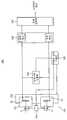
도 6은 본 발명에 의한 원소스 멀티유즈 스테레오 카메라의 바람직한 제2실시예의 블록도를 나타낸다. 도 6의 제2실시예는 상술한 실시예와 비교하면 카메라부의 렌즈 간격과 이미지센서 간격이 서로 독립적으로 조정되는 방식을 나타낸다.Fig. 6 shows a block diagram of a second preferred embodiment of the Elements multiuse stereo camera according to the present invention. Compared to the above-described embodiment, the second embodiment of FIG. 6 shows a method in which the lens gap and the image sensor gap of the camera unit are adjusted independently of each other.
6을 참조하면, 스테레오 카메라(200)는 카메라부(210), 한계시차 산출부(220), 카메라 간격 산출부(230), 영상 저장부(240), 영상 결합부(250)를 포함한다.Referring to FIG. 6, the
카메라부(210)는 좌측 카메라(212), 우측 카메라(214), 카메라 간격 조절부(216), 센서 간격 조절부(218)를 포함한다. 좌우측 카메라들(212, 214)은 간격조절부(216) 상에 서로 평행하게 설치되어 광축에 대해 수직 방향, 즉 좌우 방향으로 이동 가능하여 이들 사이의 간격이 조절 가능하다. 좌측 카메라(212)는 렌즈(LL)의 광축에 대해 좌우 방향으로 이동이 가능한 이미지 센서(SL)를 포함한다. 우측 카 메라(212)는 렌즈(LR)의 광축에 대해 좌우 방향으로 이동이 가능한 이미지 센서(SR)를 포함한다. 좌우 이미지 센서들(SL, SR)은 센서 간격 조절부(218) 상에 서로 평행하게 설치되어 상호 간격 조정이 가능하다.The
한계 시차 산출부(220)는 임의의 값으로 상기 이미지 센서들(SL, SR) 사이의 간격이 세팅된 스테레오 카메라의 초점을 피사체에 맞추고, 피사체에 초점이 맞추어진 이미지 상의 원점(Far Point) 을 결정하여 중간 사이즈를 가진 스테레오 디스플레이의 원점 제한시차로 이미지의 원점에서의 최대 허용 가능한 한계시차를 산출한다.The limit
카메라 간격 산출부(230)는 산출된 한계 시차에 의해 이미지 센서들(SL, SR) 사이의 간격 값을 산출하고, 산출된 간격 값에 응답하여 센서간격 조절부(218)를 구동한다. 또한 카메라 간격 산출부(230)는 카메라 간격 조절부(216)를 구동시켜서 렌즈 간격을 조정할 수도 있다.The
영상 저장부(240)는 수학식3에 의해 카메라 간격이 재조정된 스테레오 카메라를 통하여 각각 좌측 영상과 우측 영상을 획득하여 저장한다.The
영상 결합부(250)는 영상 저장부에 저장된 좌측 영상과 우측 영상을 각각 좌우측방향으로 시프트하여 제로시차의 위치가 일치하도록 오버랩시켜서 시차가 존재한 스테레오 영상으로 결합한다. 결합된 스테레오 양상은 스테레오 디스플레이를 통해 표시된다.The
제2실시예에서는 임의의 값으로 평행 광축을 가진 좌우 이미지센서들(SL, SR) 간격이 세팅된 스테레오 카메라의 초점을 피사체에 맞춘 다음에 피사체에 초점이 맞추어진 이미지 상의 원점을 결정한다. 이어서 중간 사이즈를 가진 스테레오 디스플레이의 원점 제한시차로 이미지의 원점에서의 최대 허용 가능한 한계시차를 산출하고 산출된 한계시차에 의해 좌우 이미지센서들(SL, SR) 사이의 간격을 재조정한다. 재조정된 스테레오 카메라로 피사체를 촬영하는 것에 의해 원소스 멀티유즈 스테레오 영상 컨텐츠를 생성한다.In the second embodiment, the stereo camera is set to a subject at which the left and right image sensors SL and SR having a parallel optical axis are set to an arbitrary value, and then the origin on the image focused on the subject is determined. . Subsequently, the maximum allowable marginal parallax at the origin of the image is calculated by the origin limiting parallax of the stereo display having a medium size, and the gap between the left and right image sensors SL and SR is readjusted by the calculated marginal parallax. By shooting a subject with a readjusted stereo camera, one-times multi-use stereo image content is generated.
도 7은 본 발명에 의한 원소스 멀티유즈 스테레오 카메라의 바람직한 변형 실시예의 블록도를 나타낸다. 도 7의 변형 실시예는 상술한 제2실시예와 비교하면 센서가 고정되고 렌즈가 좌우로 이동되는 방식을 나타낸다.Fig. 7 shows a block diagram of a preferred variant of the Elements multiuse stereo camera according to the present invention. 7 shows how the sensor is fixed and the lens is moved from side to side as compared with the second embodiment described above.
7을 참조하면, 스테레오 카메라(300)는 카메라부(310), 한계시차 산출부(320), 카메라 간격 산출부(330), 영상 저장부(340), 영상 결합부(350)를 포함한다.7, the
카메라부(310)는 좌측 카메라(312), 우측 카메라(314), 카메라 간격 조절부(316), 렌즈 간격 조절부(318)를 포함한다. 좌우측 카메라들(312, 314)은 카메라 간격 조절부(316) 상에 서로 평행하게 설치되어 광축에 대해 수직 방향, 즉 좌우 방향으로 이동 가능하여 이들 사이의 간격이 조절 가능하다. 좌측 카메라(312)는 이미지 센서(SL)의 광축에 대해 좌우 방향으로 이동이 가능한 렌즈(LL)를 포함한 다. 우측 카메라(312)는 이미지 센서(SR)의 광축에 대해 좌우 방향으로 이동이 가능한 렌즈(LR)를 포함한다. 좌우 렌즈들(LL, LR)은 렌즈 간격 조절부(318) 상에 서로 평행하게 설치되어 상호 간격 조정이 가능하다.The
한계 시차 산출부(320)는 임의의 값으로 상기 렌즈들(LL, LR) 사이의 간격이 세팅된 스테레오 카메라의 초점을 피사체에 맞추고, 피사체에 초점이 맞추어진 이미지 상의 원점(Far Point) 을 결정하여 중간 사이즈를 가진 스테레오 디스플레이의 원점 제한시차로 이미지의 원점에서의 최대 허용 가능한 한계시차를 산출한다.The marginal parallax calculator 320 focuses a stereo camera having a predetermined value between the lenses LL and LR at an arbitrary value on the subject, and a far point on the image focused on the subject. The maximum allowable marginal parallax at the origin of the image is calculated by the original parallax of the stereo display having a medium size.
카메라 간격 산출부(330)는 산출된 한계 시차에 의해 렌즈들(LL, LR) 사이의 간격 값을 산출하고, 산출된 간격 값에 응답하여 렌즈 간격 조절부(318)를 구동한다. 또한 카메라 간격 산출부(330)는 카메라 간격 조절부(316)를 구동시켜서 센서 간격을 조정할 수도 있다.The
영상 저장부(340)는 수학식3에 의해 카메라 간격이 재조정된 스테레오 카메라를 통하여 각각 좌측 영상과 우측 영상을 획득하여 저장한다.The
영상 결합부(350)는 영상 저장부에 저장된 좌측 영상과 우측 영상을 각각 좌우측방향으로 시프트하여 제로시차의 위치가 일치하도록 오버랩시켜서 시차가 존재한 스테레오 영상으로 결합한다. 결합된 스테레오 양상은 스테레오 디스플레이를 통해 표시된다.The
변형 실시예에서는 임의의 값으로 평행 광축을 가진 좌우 렌즈들(LL, LR) 간격이 세팅된 스테레오 카메라의 초점을 피사체에 맞춘 다음에 피사체에 초점이 맞추어진 이미지 상의 원점을 결정한다. 이어서 중간 사이즈를 가진 스테레오 디스플레이의 원점 제한시차로 이미지의 원점에서의 최대 허용 가능한 한계시차를 산출하고 산출된 한계시차에 의해 좌우 렌즈들(LL, LR) 사이의 간격을 재조정한다. 재조정된 스테레오 카메라로 피사체를 촬영하는 것에 의해 원소스 멀티유즈 스테레오 영상 컨텐츠를 생성한다.In a modified embodiment, the stereo camera with the left and right lenses LL and LR having a parallel optical axis set to an arbitrary value is focused on the subject, and then the origin on the image focused on the subject is determined. Subsequently, the maximum allowable marginal disparity at the origin of the image is calculated by the origin limiting parallax of the stereo display having a medium size, and the gap between the left and right lenses LL and LR is readjusted by the calculated limit parallax. By shooting a subject with a readjusted stereo camera, one-times multi-use stereo image content is generated.
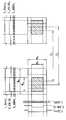
도 8은 본 발명에 의한 원소스 멀티유즈 스테레오 카메라의 바람직한 제3실시예의 블록도를 나타낸다.Fig. 8 shows a block diagram of a third preferred embodiment of the Elements multiuse stereo camera according to the present invention.
스테레오 카메라(400)는 카메라부(410), 한계시차 산출부(420), 카메라 간격 산출부(430), 영상 저장부(440), 영상 결합부(450)를 포함한다.The
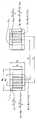
카메라부(410)는 좌측 카메라(412), 우측 카메라(414)를 포함한다. 좌우측 카메라들(412, 414)은 서로 평행하게 고정 설치된다. 좌우측 카메라들(412, 414)의 좌우 이미지 센서들(WSL,WSR) 및 좌우 광역렌즈들(WLL, WLR)은 상술한 실시예들의 이미지센서들(SL,SR) 및 좌우 렌즈들(LL, LR)의 사이즈에 비하여 이들의 최대 허용 가능한 이동거리를 포함하는 정도의 더 큰 사이즈를 가진다. 도 9를 참조하면, 좌우 이미지 센서들(WSL,WSR)은 표시 영상 면적(WO × HO)에 비하여 광역 촬상면적(WW× HW)을 가진다.The
한계 시차 산출부(420)는 고정된 간격의 스테레오 카메라의 초점을 피사체에 맞추고, 피사체에 초점이 맞추어진 이미지 상의 원점(Far Point) 을 결정하여 중간 사이즈를 가진 스테레오 디스플레이의 원점 제한시차로 이미지의 원점에서의 최대 허용 가능한 한계시차를 산출한다.The
카메라 간격 산출부(430)는 산출된 한계 시차에 의해 가상의 카메라들 사이의 간격 값을 산출한다.The
영상 저장부(440)는 어드레스 발생부(442), 좌측 영상 저장부(444), 우측 영상 저장부(446)를 포함한다. 좌우측 영상 저장부(444, 446)는 이미지 센서들(WSL,WSR)의 사이즈에 대응하여 광역 촬상면적(WW× HW)을 저장할 수 있는 큰 사이즈의 저장영역을 가진다. 어드레스 발생부(442)는 스테레오 카메라를 통하여 촬상된 좌측 영상과 우측 영상은 광역 촬상면적(WW× HW) 사이즈 그대로 각각 좌우측 영상 저장부(444, 446)에 저장되도록 기입어드레스를 발생한다. 어드레스 발생부(442)는 좌우측 영상 저장부(444, 446)에 저장된 영상 데이터를 독출하고자 할 경우에는 카메라 간격 산출부(430)에서 산출된 간격 조절값에 응답하여 재조정된 간격값(CC)에 대응하는 좌우측 방향으로 각각 시프트된 좌우 영상 독출 어드레스(L(i-(CC-CO)/2)j, L(i+WO -(CC-CO)/2)(j+HO))(R(i+(CC-CO)/2)j, R(i+WO+(CC-CO)/2)(j+HO))를 각각 발생한다. 따라서 독출된 영상 데이터는 도 9에 도시한 사선 쳐진 영역의 좌우측 영상 데이터들이 독출된다.The
영상 결합부(450)는 영상 저장부(430)에서 독출된 좌측 영상과 우측 영상을 각각 좌우측방향으로 시프트하여 제로시차의 위치가 일치하도록 오버랩시켜서 시차가 존재한 스테레오 영상으로 결합한다. 결합된 스테레오 양상은 스테레오 디스플레이를 통해 표시된다.The
도 10은 본 발명에 의한 원소스 멀티유즈 스테레오 카메라의 바람직한 제4실시예의 블록도를 나타내고 도 11은 도10의 어드레스 발생부의 어드레스 동작을 설명하기 위한 도면이다.FIG. 10 is a block diagram of a fourth preferred embodiment of an elemental multiuse stereo camera according to the present invention, and FIG. 11 is a view for explaining an address operation of the address generator of FIG.
도 10의 제4실시예는 제3실시예와 비교하면 독출 어드레스 대신에 기입어드레스를 카메라 간격 산출값에 응답하여 재조정하는 점이 다르다. 제4실시예의 스테레오 카메라(500)는 카메라부(510), 한계시차 산출부(520), 카메라 간격 산출부(530), 영상 저장부(540), 영상 결합부(550)를 포함한다.The fourth embodiment of FIG. 10 differs from the third embodiment in that the write address is readjusted in response to the camera interval calculation value instead of the read address. The
카메라부(510)는 좌측 카메라(512), 우측 카메라(514)를 포함한다. 좌우측 카메라들(512, 514)은 서로 평행하게 고정 설치된다. 좌우측 카메라들(512, 514)의 좌우 이미지 센서들(WSL,WSR) 및 좌우 광역렌즈들(WLL, WLR)은 상술한 제1 및 제2실시예들의 이미지센서들(SL,SR) 및 좌우 렌즈들(LL, LR)의 사이즈에 비하여 이들의 최대 허용 가능한 이동거리를 포함하는 정도의 더 큰 사이즈를 가진다. 도 11을 참조하면, 좌우 이미지 센서들(WSL,WSR)은 표시 영상 면적(WO × HO)에 비하여 광역 촬상면적(WW× HW)을 가진다.The
한계 시차 산출부(520)는 고정된 간격의 스테레오 카메라의 초점을 피사체에 맞추고, 피사체에 초점이 맞추어진 이미지 상의 원점(Far Point) 을 결정하여 중간 사이즈를 가진 스테레오 디스플레이의 원점 제한시차로 이미지의 원점에서의 최대 허용 가능한 한계시차를 산출한다.The
카메라 간격 산출부(530)는 산출된 한계 시차에 의해 가상의 카메라들 사이의 간격 값을 산출한다.The
영상 저장부(540)는 어드레스 발생부(542), 좌측 영상 저장부(544), 우측 영상 저장부(546)를 포함한다. 좌우측 영상 저장부(544, 546)는 이미지 센서들(WSL,WSR)의 사이즈에 대응하여 광역 촬상면적(WW× HW)을 저장할 수 있는 큰 사이즈의 저장영역을 가진다.The
어드레스 발생부(542)는 좌우 이미지 센서들((WSL,WSR)로부터 공급되는 좌우 동기신호들 SyncL(L_SyncL, F_SyncL), SyncR(L_SyncR F_SyncR)을 입력한다. 어드레스 발생부(542)는 카메라 간격 산출부(530)로부터 산출된 재조정 카메라 간격값(Cc)에 응답하여 도 11에 도시한 X 어드레스 밸리드 신호(Y_ValidL, Y_ValidR), X 어드레스 밸리드 신호(X_ValidL, X_ValidR)를 생성하고 생성된 X 어드레스 밸리드 신호(Y_ValidL, Y_ValidR), X 어드레스 밸리드 신호(X_ValidL, X_ValidR)에 응답하여 저장영역(540)의 Y 어드레스(Y_AddrL, Y_AddrR)와 X 어드레스(X_AddrL, X_AddrR)의 유효구간(사선처진 영역)의 신호만 유효 어드레스로 발생한다. 그러므로 저장영역(544, 546)에는 도 11에 사선 표시된 영역으로 제한된 각각 밸리드 구간의 어드레스에 대응하는 픽셀 데이터들만 저장된다. 독출시에는 표시영역으로 한정된 저장 데이터만 독출되므로 표시 사이즈의 좌우 영상 데이터들이 독출되어 영상 결합부(550)에 제공된다.The
영상 결합부(550)는 영상 저장부(430)에서 독출된 좌측 영상과 우측 영상을 각각 좌우측방향으로 시프트하여 제로시차의 위치가 일치하도록 오버랩시켜서 시차가 존재한 스테레오 영상으로 결합한다. 결합된 스테레오 양상은 스테레오 디스플레이를 통해 표시된다.The image combiner 550 shifts the left image and the right image read out from the
도 12는 본 발명에 의한 원소스 멀티유즈 스테레오 카메라의 바람직한 제5실시예의 블록도를 나타내고 도 13은 도12의 이미지 센서의 픽셀데이터 출력 동작을 설명하기 위한 도면이다.FIG. 12 is a block diagram of a fifth preferred embodiment of an elemental multiuse stereo camera according to the present invention, and FIG. 13 is a view for explaining an operation of outputting pixel data of the image sensor of FIG.
도 12의 제5실시예는 광역 촬상 영역(WW× HW)을 가진 이미지 센서(WSL,WSR)에서 출력되는 필셀 데이터를 카메라 간격 산출값에 응답하여 재조정하는 점이 다르다. 제5실시예의 스테레오 카메라(600)는 카메라부(610), 한계시차 산출부(620), 카메라 간격 산출부(630), 영상 저장부(640), 영상 결합부(650)를 포함한다.The fifth embodiment of FIG. 12 differs in that the pixel data output from the image sensors WSL and WSR having the wide-area imaging area WW × HW is readjusted in response to the camera interval calculation value. The
카메라부(610)는 좌측 카메라(612), 우측 카메라(614)를 포함한다. 좌우측 카메라들(612, 614)은 서로 평행하게 고정 설치된다. 좌우측 카메라들(612, 614)의 좌우 이미지 센서들(WSL,WSR) 및 좌우 광역렌즈들(WLL, WLR)은 상술한 제1 및 제2실시예들의 이미지센서들(SL,SR) 및 좌우 렌즈들(LL, LR)의 사이즈에 비하여 이들의 최대 허용 가능한 이동거리를 포함하는 정도의 더 큰 사이즈를 가진다. 도 13을 참조하면, 좌우 이미지 센서들(WSL,WSR)은 표시 영상 면적(WO × HO)에 비하여 광역 촬 상면적(WW× HW)을 가진다.The
이미지 센서들(WSL,WSR)은 도 13에 도시한 바와 같이 라인 밸리드 신호(L_ValidL ), 프레임 밸리드 신호(F_ValidR)에 응답하여 광역 사이즈(WW× HW)의 픽셀데이터를 출력한다. 또한, 제5실시예의 이미지 센서들(WSL,WSR)은 도 13에 도시한 바와 같이 조정된 라인 밸리드 신호(CL_ValidL, CL_ValidR), 조정된 프레임 밸리드 신호(CF_ValidL, CF_ValidR)에 응답하여 표시 사이즈(WO× HO)의 픽셀데이터를 출력한다. 조정된 라인 밸리드 신호(CL_ValidL, CL_ValidR), 조정된 프레임 밸리드 신호(CF_ValidL, CF_ValidR)는 카메라 간격 산출부(630)에서 산출된 간격값에 응답하여 발생된다. 그러므로 이미지센서들(WSL,WSR)에서 픽셀클록신호(PC)의 유효구간은 조정된 라인 밸리드 신호(CL_ValidL, CL_ValidR )에 의해 조정되어 1 라인에서 유효구간에 대응하는 픽셀 데이터만 유효 라인 데이터로 출력된다. 또한, 이미지센서들(WSL,WSR)에서 조정된 라인 밸리드 신호(CL_ValidL, CL_ValidR )들의 유효구간은 조정된 프레임 밸리드 신호((CF_ValidR, CL_ValidR )에 의해 조정되어 1 프레임에서 유효구간에 대응하는 라인 데이터들만 유효 프레임 데이터로 출력된다.As illustrated in FIG. 13, the image sensors WSL and WSR have pixel data of a wide area size WW × HW in response to the line valid signal L_ValidL and the frame valid signal F_ValidR. Outputs Further, the fifth embodiment image sensors (WSL, WSR) is one of line valid signal adjustment as shown in Figure 13 (CL_ValidL, CL_ValidR), the adjusted frame valid signal (CF_ValidL, CF_ValidR ) in response to the output pixel data of a display size (W ×OO H). The adjusted line valid signals CL_ValidL and CL_ValidR and the adjusted frame valid signals CF_ValidL and CF_ValidR are generated in response to the interval value calculated by the
한계 시차 산출부(620)는 고정된 간격의 스테레오 카메라의 초점을 피사체에 맞추고, 피사체에 초점이 맞추어진 이미지 상의 원점(Far Point) 을 결정하여 중간 사이즈를 가진 스테레오 디스플레이의 원점 제한시차로 이미지의 원점에서의 최대 허용 가능한 한계시차를 산출한다.The
카메라 간격 산출부(630)는 산출된 한계 시차에 의해 가상의 카메라들 사이의 간격 값을 산출한다.The
카메라 간격 산출부(330)는 산출된 한계 시차에 의해 렌즈들(LL, LR) 사이의 간격 값을 산출하고, 산출된 간격 값에 응답하여 렌즈 간격 조절부(318)를 구동한다. 또한 카메라 간격 산출부(330)는 카메라 간격 조절부(316)를 구동시켜서 센서 간격을 조정할 수도 있다.The
영상 저장부(640)는 이미지센서들로부터 출력된 표시 사이즈(WO× HO)의 좌우측 영상들을 입력받아 저장한다.The
영상 결합부(650)는 영상 저장부에 저장된 좌측 영상과 우측 영상을 각각 좌우측방향으로 시프트하여 제로시차의 위치가 일치하도록 오버랩시켜서 시차가 존재한 스테레오 영상으로 결합한다. 결합된 스테레오 양상은 스테레오 디스플레이를 통해 표시된다.The
본 발명에 의해 제작된 스테레오 영상은 한번의 제작에 의해 소형의 휴대폰, 데스크 탑 컴퓨터, 가정용 텔레비전, 대형 프로젝션, 영화관 등의 다양한 사이즈의 디스플레이 환경에서 두통이나 어지럼증 없이 입체영상을 즐길 수 있게 함으로써 입체영상의 콘텐츠의 시장을 확대시킬 수 있다.The stereo image produced by the present invention enables stereoscopic images to be enjoyed without headaches or dizziness in a display environment of various sizes such as a small mobile phone, a desktop computer, a home television, a large projection, a movie theater, etc. by a single production. To expand the market of content.
상기에서는 본 발명의 바람직한 실시예를 참조하여 설명하였지만, 해당 기술 분야의 숙련된 당업자는 하기의 특허 청구의 범위에 기재된 본 발명의 사상 및 영역으로부터 벗어나지 않는 범위 내에서 본 발명을 다양하게 수정 및 변경시킬 수 있음을 이해할 수 있을 것이다.Although described above with reference to a preferred embodiment of the present invention, those skilled in the art will be variously modified and changed within the scope of the invention without departing from the spirit and scope of the invention described in the claims below I can understand that you can.
도 1은 본 발명에 의한 원소스 멀티유즈 스테레오 카메라의 바람직한 일 실시예의 블록도를 나타낸다.Fig. 1 shows a block diagram of a preferred embodiment of an elemental multiuse stereo camera according to the present invention.
도 2는 스테레오 디스플레이의 원점 제한시차와 스테레오 카메라의 한계시차의 관계를 설명하기 위한 도면이다.FIG. 2 is a diagram for describing a relationship between the origin limited parallax of a stereo display and the limited parallax of a stereo camera.
도 3은 본 발명의 카메라부의 좌우 카메라들과 피사체 사이의 광학적 기하관계를 나타낸다.3 illustrates an optical geometric relationship between left and right cameras and a subject of a camera unit of the present invention.
도 4는 초기 카메라 간격에서의 이미지 센서에 촬상된 좌우 이미지들의 기하 구조와 합성된 스테레오 이미지를 나타낸다.4 illustrates a stereo image synthesized with a geometry of left and right images captured by an image sensor at an initial camera interval.
도 5는 본 발명에 의해 재조정된 카메라 간격에서의 이미지 센서에 촬상된 좌우 이미지들의 기하구조와 합성된 스테레오 이미지를 나타낸다.5 shows a stereo image synthesized with the geometry of the left and right images captured by the image sensor at the camera interval readjusted by the present invention.
도 6은 본 발명에 의한 원소스 멀티유즈 스테레오 카메라의 바람직한 다른 실시예의 블록도를 나타낸다.Fig. 6 shows a block diagram of another preferred embodiment of the Elements multiuse stereo camera according to the present invention.
도 7은 본 발명에 의한 원소스 멀티유즈 스테레오 카메라의 바람직한 변형 실시예의 블록도를 나타낸다.Fig. 7 shows a block diagram of a preferred variant of the Elements multiuse stereo camera according to the present invention.
도 8은 본 발명에 의한 원소스 멀티유즈 스테레오 카메라의 바람직한 또 다른 실시예의 블록도를 나타낸다.Fig. 8 shows a block diagram of another preferred embodiment of the Elements multiuse stereo camera according to the present invention.
도 9는 도 8의 또 다른 실시예의 동작을 설명하기 위한 도면이다.9 is a view for explaining the operation of another embodiment of FIG.
도 10은 본 발명에 의한 원소스 멀티유즈 스테레오 카메라의 바람직한 제4실시예의 블록도를 나타낸다.Fig. 10 shows a block diagram of a fourth preferred embodiment of the Elements multiuse stereo camera according to the present invention.
도 11은 도10의 어드레스 발생부의 어드레스 동작을 설명하기 위한 도면이다.FIG. 11 is a diagram for describing an address operation of the address generator of FIG. 10.
도 12는 본 발명에 의한 원소스 멀티유즈 스테레오 카메라의 바람직한 제5실시예의 블록도를 나타낸다.Fig. 12 shows a block diagram of a fifth preferred embodiment of the Elements multiuse stereo camera according to the present invention.
도 13은 도12의 이미지 센서의 픽셀데이터 출력 동작을 설명하기 위한 도면이다.FIG. 13 is a diagram for describing an operation of outputting pixel data of the image sensor of FIG. 12.
Claims (33)
Translated fromKoreanPriority Applications (10)
| Application Number | Priority Date | Filing Date | Title |
|---|---|---|---|
| KR1020070100904AKR101313740B1 (en) | 2007-10-08 | 2007-10-08 | OSMU( One Source Multi Use)-type Stereoscopic Camera and Method of Making Stereoscopic Video Content thereof |
| JP2010528799AJP5572094B2 (en) | 2007-10-08 | 2008-10-08 | One-source multi-use (OSMU) type stereo camera and method for producing stereo image content thereof |
| BRPI0818500BRPI0818500A2 (en) | 2007-10-08 | 2008-10-08 | Osmu-type stereoscopic camera (multiple use of one source) and method of manufacturing stereoscopic video content |
| EP10006847.7AEP2230858A3 (en) | 2007-10-08 | 2008-10-08 | OSMU (one source multi use)-type stereoscopic camera and method of making stereoscopic video content thereof |
| MX2010003645AMX2010003645A (en) | 2007-10-08 | 2008-10-08 | Osmu(one source multi use)-type stereoscopic camera and method of making stereoscopic video content thereof. |
| EP08836985.5AEP2201785A4 (en) | 2007-10-08 | 2008-10-08 | Osmu(one source multi use)-type stereoscopic camera and method of making stereoscopic video content thereof |
| US12/734,017US8482600B2 (en) | 2007-10-08 | 2008-10-08 | OSMU (one source multi use)-type stereoscopic camera and method of making stereoscopic video content thereof |
| CA2701785ACA2701785C (en) | 2007-10-08 | 2008-10-08 | Osmu (one source multi use)-type stereoscopic camera and method of making stereoscopic video content thereof |
| PCT/KR2008/005897WO2009048254A1 (en) | 2007-10-08 | 2008-10-08 | Osmu(one source multi use)-type stereoscopic camera and method of making stereoscopic video content thereof |
| CN2008801140863ACN101843107B (en) | 2007-10-08 | 2008-10-08 | OSMU (One Source Multiple Use) Stereo Camera and Method for Making Stereo Video Content |
Applications Claiming Priority (1)
| Application Number | Priority Date | Filing Date | Title |
|---|---|---|---|
| KR1020070100904AKR101313740B1 (en) | 2007-10-08 | 2007-10-08 | OSMU( One Source Multi Use)-type Stereoscopic Camera and Method of Making Stereoscopic Video Content thereof |
Related Child Applications (1)
| Application Number | Title | Priority Date | Filing Date |
|---|---|---|---|
| KR1020130035759ADivisionKR101376734B1 (en) | 2013-04-02 | 2013-04-02 | OSMU( One Source Multi Use)-type Stereoscopic Camera and Method of Making Stereoscopic Video Content thereof |
Publications (2)
| Publication Number | Publication Date |
|---|---|
| KR20090035880A KR20090035880A (en) | 2009-04-13 |
| KR101313740B1true KR101313740B1 (en) | 2013-10-15 |
Family
ID=40549359
Family Applications (1)
| Application Number | Title | Priority Date | Filing Date |
|---|---|---|---|
| KR1020070100904AActiveKR101313740B1 (en) | 2007-10-08 | 2007-10-08 | OSMU( One Source Multi Use)-type Stereoscopic Camera and Method of Making Stereoscopic Video Content thereof |
Country Status (9)
| Country | Link |
|---|---|
| US (1) | US8482600B2 (en) |
| EP (2) | EP2201785A4 (en) |
| JP (1) | JP5572094B2 (en) |
| KR (1) | KR101313740B1 (en) |
| CN (1) | CN101843107B (en) |
| BR (1) | BRPI0818500A2 (en) |
| CA (1) | CA2701785C (en) |
| MX (1) | MX2010003645A (en) |
| WO (1) | WO2009048254A1 (en) |
Families Citing this family (36)
| Publication number | Priority date | Publication date | Assignee | Title |
|---|---|---|---|---|
| US8791984B2 (en)* | 2007-11-16 | 2014-07-29 | Scallop Imaging, Llc | Digital security camera |
| JP5425554B2 (en)* | 2009-07-27 | 2014-02-26 | 富士フイルム株式会社 | Stereo imaging device and stereo imaging method |
| KR101121421B1 (en)* | 2010-02-23 | 2012-03-20 | 주식회사 빅아이 | Method and computer readable recording medium for providing optimal distance between cameras in stereoscopic video production and apparatus for producing stereoscopic video |
| US20110242342A1 (en) | 2010-04-05 | 2011-10-06 | Qualcomm Incorporated | Combining data from multiple image sensors |
| US8896668B2 (en)* | 2010-04-05 | 2014-11-25 | Qualcomm Incorporated | Combining data from multiple image sensors |
| WO2011136137A1 (en)* | 2010-04-28 | 2011-11-03 | 富士フイルム株式会社 | Stereoscopic image pickup device and control method therefor |
| EP2395765B1 (en)* | 2010-06-14 | 2016-08-24 | Nintendo Co., Ltd. | Storage medium having stored therein stereoscopic image display program, stereoscopic image display device, stereoscopic image display system, and stereoscopic image display method |
| TW201200959A (en)* | 2010-06-29 | 2012-01-01 | Fujifilm Corp | One-eyed stereo photographic device |
| EP2434764A1 (en)* | 2010-09-23 | 2012-03-28 | Thomson Licensing | Adaptation of 3D video content |
| JP5681588B2 (en)* | 2010-09-30 | 2015-03-11 | 富士フイルム株式会社 | Stereoscopic image editing apparatus and stereoscopic image editing method |
| US8879902B2 (en)* | 2010-10-08 | 2014-11-04 | Vincent Pace & James Cameron | Integrated 2D/3D camera with fixed imaging parameters |
| CN103329549B (en) | 2011-01-25 | 2016-03-09 | 富士胶片株式会社 | Dimensional video processor, stereoscopic imaging apparatus and three-dimensional video-frequency processing method |
| CN103339948B (en)* | 2011-02-03 | 2015-04-08 | 富士胶片株式会社 | 3D video playing device, 3D imaging device, and 3D video playing method |
| KR101824439B1 (en) | 2011-02-16 | 2018-02-02 | 주식회사 스테레오피아 | Mobile Stereoscopic Camera Apparatus and Method of Shooting thereof |
| KR101219859B1 (en)* | 2011-08-31 | 2013-01-09 | 성균관대학교산학협력단 | Apparatus and method for semi-auto convergence in 3d photographing apparatus |
| KR20130024504A (en)* | 2011-08-31 | 2013-03-08 | 삼성전기주식회사 | Stereo camera system and method for controlling convergence |
| US20140225991A1 (en)* | 2011-09-02 | 2014-08-14 | Htc Corporation | Image capturing apparatus and method for obatining depth information of field thereof |
| US20130057655A1 (en)* | 2011-09-02 | 2013-03-07 | Wen-Yueh Su | Image processing system and automatic focusing method |
| JP5667304B2 (en)* | 2011-09-13 | 2015-02-12 | 富士フイルム株式会社 | Stereo imaging device |
| JP5989315B2 (en)* | 2011-09-22 | 2016-09-07 | 任天堂株式会社 | Display control program, display control system, display control apparatus, and display control method |
| KR101888967B1 (en) | 2011-12-16 | 2018-08-20 | 엘지이노텍 주식회사 | 3-dimensional camera module and method for auto focusing the same |
| US20130208107A1 (en)* | 2012-02-14 | 2013-08-15 | Nokia Corporation | Apparatus and a Method for Producing a Depth-Map |
| US9743069B2 (en)* | 2012-08-30 | 2017-08-22 | Lg Innotek Co., Ltd. | Camera module and apparatus for calibrating position thereof |
| CN103888750B (en)* | 2012-12-20 | 2016-02-24 | 比比威株式会社 | 3-dimensional image shoot control system and method |
| US20140267617A1 (en)* | 2013-03-15 | 2014-09-18 | Scott A. Krig | Adaptive depth sensing |
| US9282265B2 (en)* | 2013-09-09 | 2016-03-08 | Omnivision Technologies, Inc. | Camera devices and systems based on a single image sensor and methods for manufacturing the same |
| US10045005B2 (en) | 2013-12-10 | 2018-08-07 | Lg Electronics Inc. | 3D camera module |
| KR102357290B1 (en)* | 2014-03-25 | 2022-01-28 | 임머비젼, 인코퍼레이티드 | Automated definition of system behavior or user experience by recording, sharing, and processing information associated with wide-angle image |
| US9262801B2 (en) | 2014-04-01 | 2016-02-16 | Gopro, Inc. | Image taping in a multi-camera array |
| US11019323B2 (en)* | 2015-02-06 | 2021-05-25 | Tara Chand Singhal | Apparatus and method for 3D like camera system in a handheld mobile wireless device |
| US10119809B2 (en)* | 2015-02-16 | 2018-11-06 | Intel Corporation | Simulating multi-camera imaging systems |
| CN106331679B (en)* | 2015-06-30 | 2018-07-06 | 深圳市墨克瑞光电子研究院 | Binocular camera spacing adjusting method and device |
| US9953403B2 (en)* | 2016-06-10 | 2018-04-24 | The Boeing Company | Stereoscopic camera and associated method of varying a scale of a stereoscopic image pair |
| CN109716746B (en)* | 2016-09-13 | 2021-06-01 | Lg伊诺特有限公司 | Dual camera module, optical device, camera module, and method for operating a camera module |
| CN109525830A (en)* | 2018-11-28 | 2019-03-26 | 浙江未来技术研究院(嘉兴) | A kind of dimensional video collecting system |
| CN111726599B (en)* | 2019-03-22 | 2022-04-05 | 舜宇光学(浙江)研究院有限公司 | Matching method of binocular different-internal-reference camera-imaging optical system, system and electronic equipment |
Citations (3)
| Publication number | Priority date | Publication date | Assignee | Title |
|---|---|---|---|---|
| KR20010003426A (en)* | 1999-06-23 | 2001-01-15 | 미노루 이나바 | Stereo camera |
| KR20060009178A (en)* | 2004-07-21 | 2006-01-31 | 한국방송공사 | Driving device and control method of binocular stereo camera system |
| JP2006303832A (en)* | 2005-04-19 | 2006-11-02 | Minoru Inaba | Digital stereo camera or digital stereo video camera |
Family Cites Families (16)
| Publication number | Priority date | Publication date | Assignee | Title |
|---|---|---|---|---|
| US5063441A (en)* | 1990-10-11 | 1991-11-05 | Stereographics Corporation | Stereoscopic video cameras with image sensors having variable effective position |
| DE69417824T4 (en)* | 1993-08-26 | 2000-06-29 | Matsushita Electric Industrial Co., Ltd. | Stereoscopic scanner |
| US6005607A (en)* | 1995-06-29 | 1999-12-21 | Matsushita Electric Industrial Co., Ltd. | Stereoscopic computer graphics image generating apparatus and stereoscopic TV apparatus |
| JPH10155104A (en)* | 1996-11-22 | 1998-06-09 | Canon Inc | Compound eye imaging method and apparatus, and storage medium |
| JPH11341522A (en)* | 1998-05-22 | 1999-12-10 | Fuji Photo Film Co Ltd | Stereoscopic image photographing device |
| JP4149037B2 (en)* | 1998-06-04 | 2008-09-10 | オリンパス株式会社 | Video system |
| DE19927128A1 (en)* | 1999-06-11 | 2000-12-28 | Minoru Inaba | Stereo camera; has right and left objectives spaced between spacing between centres of two images and spacing between optical axes of objectives for shortest picture distance |
| JP2001016619A (en)* | 1999-06-30 | 2001-01-19 | Canon Inc | Imaging device, method of determining convergence distance thereof, storage medium, and optical device |
| EP1085769B1 (en)* | 1999-09-15 | 2012-02-01 | Sharp Kabushiki Kaisha | Stereoscopic image pickup apparatus |
| JP2001218228A (en)* | 2000-02-01 | 2001-08-10 | Canon Inc | Optical system for stereoscopic image photographing and stereoscopic image photographing apparatus using the same |
| JP3749227B2 (en)* | 2002-03-27 | 2006-02-22 | 三洋電機株式会社 | Stereoscopic image processing method and apparatus |
| JP4490074B2 (en)* | 2003-04-17 | 2010-06-23 | ソニー株式会社 | Stereoscopic image processing apparatus, stereoscopic image display apparatus, stereoscopic image providing method, and stereoscopic image processing system |
| US20050207486A1 (en)* | 2004-03-18 | 2005-09-22 | Sony Corporation | Three dimensional acquisition and visualization system for personal electronic devices |
| JP2005297168A (en)* | 2004-04-16 | 2005-10-27 | Fujinon Corp | Remote control robot |
| DE102005063503B4 (en) | 2005-03-10 | 2011-05-19 | Inaba, Minoru, Oyama | 3D display and 3D projector |
| DE202007010389U1 (en)* | 2007-07-24 | 2007-09-27 | Maier, Florian | Device for automatic positioning of coupled cameras for plastic imaging |
- 2007
- 2007-10-08KRKR1020070100904Apatent/KR101313740B1/enactiveActive
- 2008
- 2008-10-08CNCN2008801140863Apatent/CN101843107B/enactiveActive
- 2008-10-08MXMX2010003645Apatent/MX2010003645A/ennot_activeApplication Discontinuation
- 2008-10-08EPEP08836985.5Apatent/EP2201785A4/ennot_activeWithdrawn
- 2008-10-08CACA2701785Apatent/CA2701785C/ennot_activeExpired - Fee Related
- 2008-10-08EPEP10006847.7Apatent/EP2230858A3/ennot_activeWithdrawn
- 2008-10-08BRBRPI0818500patent/BRPI0818500A2/ennot_activeIP Right Cessation
- 2008-10-08USUS12/734,017patent/US8482600B2/enactiveActive
- 2008-10-08WOPCT/KR2008/005897patent/WO2009048254A1/enactiveApplication Filing
- 2008-10-08JPJP2010528799Apatent/JP5572094B2/enactiveActive
Patent Citations (3)
| Publication number | Priority date | Publication date | Assignee | Title |
|---|---|---|---|---|
| KR20010003426A (en)* | 1999-06-23 | 2001-01-15 | 미노루 이나바 | Stereo camera |
| KR20060009178A (en)* | 2004-07-21 | 2006-01-31 | 한국방송공사 | Driving device and control method of binocular stereo camera system |
| JP2006303832A (en)* | 2005-04-19 | 2006-11-02 | Minoru Inaba | Digital stereo camera or digital stereo video camera |
Also Published As
| Publication number | Publication date |
|---|---|
| MX2010003645A (en) | 2010-08-09 |
| EP2230858A3 (en) | 2014-02-19 |
| US20100231691A1 (en) | 2010-09-16 |
| CN101843107B (en) | 2012-08-15 |
| EP2201785A4 (en) | 2014-02-19 |
| BRPI0818500A2 (en) | 2015-04-22 |
| CA2701785A1 (en) | 2009-04-16 |
| CA2701785C (en) | 2016-05-17 |
| US8482600B2 (en) | 2013-07-09 |
| JP5572094B2 (en) | 2014-08-13 |
| JP2010541513A (en) | 2010-12-24 |
| CN101843107A (en) | 2010-09-22 |
| EP2201785A1 (en) | 2010-06-30 |
| EP2230858A2 (en) | 2010-09-22 |
| KR20090035880A (en) | 2009-04-13 |
| WO2009048254A1 (en) | 2009-04-16 |
Similar Documents
| Publication | Publication Date | Title |
|---|---|---|
| KR101313740B1 (en) | OSMU( One Source Multi Use)-type Stereoscopic Camera and Method of Making Stereoscopic Video Content thereof | |
| CN103477645B (en) | Stereo camera device for mobile equipment and shooting method thereof | |
| JP3944188B2 (en) | Stereo image display method, stereo image imaging method, and stereo image display apparatus | |
| US7190825B2 (en) | Portable communication device for stereoscopic image display and transmission | |
| JP4328311B2 (en) | Method and program for creating multi-viewpoint image for 3D image display | |
| US20110193945A1 (en) | Image display device, image display viewing system and image display method | |
| KR20150068299A (en) | Method and system of generating images for multi-surface display | |
| KR100971730B1 (en) | Parallel axis stereoscopic camera | |
| KR20160143623A (en) | layered Hologram System using Auto-stereoscopic 3D image | |
| US20120154543A1 (en) | Document camera, method for controlling document camera, program, and display processing system | |
| US9154771B2 (en) | Apparatus for capturing stereoscopic image | |
| CN103220544B (en) | Active off-axis parallel type stereo imaging method | |
| WO2012124331A1 (en) | Three-dimensional image pickup device | |
| KR101376734B1 (en) | OSMU( One Source Multi Use)-type Stereoscopic Camera and Method of Making Stereoscopic Video Content thereof | |
| US9258547B2 (en) | Intelligent device with both recording and playing back 3D movies and the relevant apparatus and methods | |
| KR101686634B1 (en) | layered Hologram System using Auto-stereoscopic 3D image | |
| JP2008167310A (en) | Naked eye stereoscopic vision image processing method, device, and recording medium recording operation program | |
| JP2013105000A (en) | Video display device and video display method | |
| JP4481275B2 (en) | 3D video information transmission method | |
| JP7339278B2 (en) | Stereoscopic display adjusted to the viewer | |
| KR20160095500A (en) | 3D Hologram System using Auto-stereoscopic 3D image | |
| JP2015056796A (en) | Stereoscopic image processing apparatus, imaging apparatus, stereoscopic image processing method and stereoscopic image processing program | |
| JP2025067473A (en) | Electronic apparatus | |
| HK1142427B (en) | Stereoscopic image generation device and stereoscopic image generation method |
Legal Events
| Date | Code | Title | Description |
|---|---|---|---|
| PA0109 | Patent application | Patent event code:PA01091R01D Comment text:Patent Application Patent event date:20071008 | |
| PG1501 | Laying open of application | ||
| A201 | Request for examination | ||
| PA0201 | Request for examination | Patent event code:PA02012R01D Patent event date:20110908 Comment text:Request for Examination of Application Patent event code:PA02011R01I Patent event date:20071008 Comment text:Patent Application | |
| PE0902 | Notice of grounds for rejection | Comment text:Notification of reason for refusal Patent event date:20120820 Patent event code:PE09021S01D | |
| AMND | Amendment | ||
| E601 | Decision to refuse application | ||
| PE0601 | Decision on rejection of patent | Patent event date:20130227 Comment text:Decision to Refuse Application Patent event code:PE06012S01D Patent event date:20120820 Comment text:Notification of reason for refusal Patent event code:PE06011S01I | |
| J201 | Request for trial against refusal decision | ||
| PJ0201 | Trial against decision of rejection | Patent event date:20130328 Comment text:Request for Trial against Decision on Refusal Patent event code:PJ02012R01D Patent event date:20130227 Comment text:Decision to Refuse Application Patent event code:PJ02011S01I Appeal kind category:Appeal against decision to decline refusal Decision date:20130916 Appeal identifier:2013101002331 Request date:20130328 | |
| A107 | Divisional application of patent | ||
| AMND | Amendment | ||
| PA0107 | Divisional application | Comment text:Divisional Application of Patent Patent event date:20130402 Patent event code:PA01071R01D | |
| PB0901 | Examination by re-examination before a trial | Comment text:Amendment to Specification, etc. Patent event date:20130402 Patent event code:PB09011R02I Comment text:Request for Trial against Decision on Refusal Patent event date:20130328 Patent event code:PB09011R01I Comment text:Amendment to Specification, etc. Patent event date:20121022 Patent event code:PB09011R02I | |
| PE0902 | Notice of grounds for rejection | Comment text:Final Notice of Reason for Refusal Patent event date:20130530 Patent event code:PE09021S02D | |
| B701 | Decision to grant | ||
| PB0701 | Decision of registration after re-examination before a trial | Patent event date:20130916 Comment text:Decision to Grant Registration Patent event code:PB07012S01D Patent event date:20130430 Comment text:Transfer of Trial File for Re-examination before a Trial Patent event code:PB07011S01I | |
| GRNT | Written decision to grant | ||
| PR0701 | Registration of establishment | Comment text:Registration of Establishment Patent event date:20130925 Patent event code:PR07011E01D | |
| PR1002 | Payment of registration fee | Payment date:20130926 End annual number:3 Start annual number:1 | |
| PG1601 | Publication of registration | ||
| FPAY | Annual fee payment | Payment date:20160926 Year of fee payment:4 | |
| PR1001 | Payment of annual fee | Payment date:20160926 Start annual number:4 End annual number:4 | |
| FPAY | Annual fee payment | Payment date:20170926 Year of fee payment:5 | |
| PR1001 | Payment of annual fee | Payment date:20170926 Start annual number:5 End annual number:5 | |
| FPAY | Annual fee payment | Payment date:20180927 Year of fee payment:6 | |
| PR1001 | Payment of annual fee | Payment date:20180927 Start annual number:6 End annual number:6 | |
| FPAY | Annual fee payment | Payment date:20190924 Year of fee payment:7 | |
| PR1001 | Payment of annual fee | Payment date:20190924 Start annual number:7 End annual number:7 | |
| PR1001 | Payment of annual fee | Payment date:20200914 Start annual number:8 End annual number:8 | |
| PR1001 | Payment of annual fee | Payment date:20220328 Start annual number:9 End annual number:9 | |
| PR1001 | Payment of annual fee | Payment date:20230327 Start annual number:10 End annual number:10 | |
| PR1001 | Payment of annual fee | Payment date:20230913 Start annual number:11 End annual number:11 | |
| PR1001 | Payment of annual fee | Payment date:20250226 Start annual number:12 End annual number:12 |