KR101312263B1 - Vehicle and method for controlling the same - Google Patents
Vehicle and method for controlling the sameDownload PDFInfo
- Publication number
- KR101312263B1 KR101312263B1KR1020120030236AKR20120030236AKR101312263B1KR 101312263 B1KR101312263 B1KR 101312263B1KR 1020120030236 AKR1020120030236 AKR 1020120030236AKR 20120030236 AKR20120030236 AKR 20120030236AKR 101312263 B1KR101312263 B1KR 101312263B1
- Authority
- KR
- South Korea
- Prior art keywords
- battery cell
- generation module
- power generation
- diode
- charging current
- Prior art date
- Legal status (The legal status is an assumption and is not a legal conclusion. Google has not performed a legal analysis and makes no representation as to the accuracy of the status listed.)
- Expired - Fee Related
Links
Images


Classifications
- H—ELECTRICITY
- H02—GENERATION; CONVERSION OR DISTRIBUTION OF ELECTRIC POWER
- H02J—CIRCUIT ARRANGEMENTS OR SYSTEMS FOR SUPPLYING OR DISTRIBUTING ELECTRIC POWER; SYSTEMS FOR STORING ELECTRIC ENERGY
- H02J7/00—Circuit arrangements for charging or depolarising batteries or for supplying loads from batteries
- H02J7/02—Circuit arrangements for charging or depolarising batteries or for supplying loads from batteries for charging batteries from AC mains by converters
- H02J7/04—Regulation of charging current or voltage
- B—PERFORMING OPERATIONS; TRANSPORTING
- B60—VEHICLES IN GENERAL
- B60L—PROPULSION OF ELECTRICALLY-PROPELLED VEHICLES; SUPPLYING ELECTRIC POWER FOR AUXILIARY EQUIPMENT OF ELECTRICALLY-PROPELLED VEHICLES; ELECTRODYNAMIC BRAKE SYSTEMS FOR VEHICLES IN GENERAL; MAGNETIC SUSPENSION OR LEVITATION FOR VEHICLES; MONITORING OPERATING VARIABLES OF ELECTRICALLY-PROPELLED VEHICLES; ELECTRIC SAFETY DEVICES FOR ELECTRICALLY-PROPELLED VEHICLES
- B60L58/00—Methods or circuit arrangements for monitoring or controlling batteries or fuel cells, specially adapted for electric vehicles
- B60L58/10—Methods or circuit arrangements for monitoring or controlling batteries or fuel cells, specially adapted for electric vehicles for monitoring or controlling batteries
- B60L58/12—Methods or circuit arrangements for monitoring or controlling batteries or fuel cells, specially adapted for electric vehicles for monitoring or controlling batteries responding to state of charge [SoC]
- B—PERFORMING OPERATIONS; TRANSPORTING
- B60—VEHICLES IN GENERAL
- B60L—PROPULSION OF ELECTRICALLY-PROPELLED VEHICLES; SUPPLYING ELECTRIC POWER FOR AUXILIARY EQUIPMENT OF ELECTRICALLY-PROPELLED VEHICLES; ELECTRODYNAMIC BRAKE SYSTEMS FOR VEHICLES IN GENERAL; MAGNETIC SUSPENSION OR LEVITATION FOR VEHICLES; MONITORING OPERATING VARIABLES OF ELECTRICALLY-PROPELLED VEHICLES; ELECTRIC SAFETY DEVICES FOR ELECTRICALLY-PROPELLED VEHICLES
- B60L3/00—Electric devices on electrically-propelled vehicles for safety purposes; Monitoring operating variables, e.g. speed, deceleration or energy consumption
- B60L3/0023—Detecting, eliminating, remedying or compensating for drive train abnormalities, e.g. failures within the drive train
- B60L3/003—Detecting, eliminating, remedying or compensating for drive train abnormalities, e.g. failures within the drive train relating to inverters
- B—PERFORMING OPERATIONS; TRANSPORTING
- B60—VEHICLES IN GENERAL
- B60L—PROPULSION OF ELECTRICALLY-PROPELLED VEHICLES; SUPPLYING ELECTRIC POWER FOR AUXILIARY EQUIPMENT OF ELECTRICALLY-PROPELLED VEHICLES; ELECTRODYNAMIC BRAKE SYSTEMS FOR VEHICLES IN GENERAL; MAGNETIC SUSPENSION OR LEVITATION FOR VEHICLES; MONITORING OPERATING VARIABLES OF ELECTRICALLY-PROPELLED VEHICLES; ELECTRIC SAFETY DEVICES FOR ELECTRICALLY-PROPELLED VEHICLES
- B60L3/00—Electric devices on electrically-propelled vehicles for safety purposes; Monitoring operating variables, e.g. speed, deceleration or energy consumption
- B60L3/04—Cutting off the power supply under fault conditions
- B—PERFORMING OPERATIONS; TRANSPORTING
- B60—VEHICLES IN GENERAL
- B60L—PROPULSION OF ELECTRICALLY-PROPELLED VEHICLES; SUPPLYING ELECTRIC POWER FOR AUXILIARY EQUIPMENT OF ELECTRICALLY-PROPELLED VEHICLES; ELECTRODYNAMIC BRAKE SYSTEMS FOR VEHICLES IN GENERAL; MAGNETIC SUSPENSION OR LEVITATION FOR VEHICLES; MONITORING OPERATING VARIABLES OF ELECTRICALLY-PROPELLED VEHICLES; ELECTRIC SAFETY DEVICES FOR ELECTRICALLY-PROPELLED VEHICLES
- B60L50/00—Electric propulsion with power supplied within the vehicle
- B60L50/20—Electric propulsion with power supplied within the vehicle using propulsion power generated by humans or animals
- B—PERFORMING OPERATIONS; TRANSPORTING
- B60—VEHICLES IN GENERAL
- B60L—PROPULSION OF ELECTRICALLY-PROPELLED VEHICLES; SUPPLYING ELECTRIC POWER FOR AUXILIARY EQUIPMENT OF ELECTRICALLY-PROPELLED VEHICLES; ELECTRODYNAMIC BRAKE SYSTEMS FOR VEHICLES IN GENERAL; MAGNETIC SUSPENSION OR LEVITATION FOR VEHICLES; MONITORING OPERATING VARIABLES OF ELECTRICALLY-PROPELLED VEHICLES; ELECTRIC SAFETY DEVICES FOR ELECTRICALLY-PROPELLED VEHICLES
- B60L50/00—Electric propulsion with power supplied within the vehicle
- B60L50/50—Electric propulsion with power supplied within the vehicle using propulsion power supplied by batteries or fuel cells
- B60L50/60—Electric propulsion with power supplied within the vehicle using propulsion power supplied by batteries or fuel cells using power supplied by batteries
- B60L50/61—Electric propulsion with power supplied within the vehicle using propulsion power supplied by batteries or fuel cells using power supplied by batteries by batteries charged by engine-driven generators, e.g. series hybrid electric vehicles
- B60L50/62—Electric propulsion with power supplied within the vehicle using propulsion power supplied by batteries or fuel cells using power supplied by batteries by batteries charged by engine-driven generators, e.g. series hybrid electric vehicles charged by low-power generators primarily intended to support the batteries, e.g. range extenders
- B—PERFORMING OPERATIONS; TRANSPORTING
- B60—VEHICLES IN GENERAL
- B60L—PROPULSION OF ELECTRICALLY-PROPELLED VEHICLES; SUPPLYING ELECTRIC POWER FOR AUXILIARY EQUIPMENT OF ELECTRICALLY-PROPELLED VEHICLES; ELECTRODYNAMIC BRAKE SYSTEMS FOR VEHICLES IN GENERAL; MAGNETIC SUSPENSION OR LEVITATION FOR VEHICLES; MONITORING OPERATING VARIABLES OF ELECTRICALLY-PROPELLED VEHICLES; ELECTRIC SAFETY DEVICES FOR ELECTRICALLY-PROPELLED VEHICLES
- B60L58/00—Methods or circuit arrangements for monitoring or controlling batteries or fuel cells, specially adapted for electric vehicles
- B60L58/10—Methods or circuit arrangements for monitoring or controlling batteries or fuel cells, specially adapted for electric vehicles for monitoring or controlling batteries
- B60L58/18—Methods or circuit arrangements for monitoring or controlling batteries or fuel cells, specially adapted for electric vehicles for monitoring or controlling batteries of two or more battery modules
- B60L58/22—Balancing the charge of battery modules
- B—PERFORMING OPERATIONS; TRANSPORTING
- B60—VEHICLES IN GENERAL
- B60L—PROPULSION OF ELECTRICALLY-PROPELLED VEHICLES; SUPPLYING ELECTRIC POWER FOR AUXILIARY EQUIPMENT OF ELECTRICALLY-PROPELLED VEHICLES; ELECTRODYNAMIC BRAKE SYSTEMS FOR VEHICLES IN GENERAL; MAGNETIC SUSPENSION OR LEVITATION FOR VEHICLES; MONITORING OPERATING VARIABLES OF ELECTRICALLY-PROPELLED VEHICLES; ELECTRIC SAFETY DEVICES FOR ELECTRICALLY-PROPELLED VEHICLES
- B60L2200/00—Type of vehicles
- B60L2200/12—Bikes
- B—PERFORMING OPERATIONS; TRANSPORTING
- B60—VEHICLES IN GENERAL
- B60L—PROPULSION OF ELECTRICALLY-PROPELLED VEHICLES; SUPPLYING ELECTRIC POWER FOR AUXILIARY EQUIPMENT OF ELECTRICALLY-PROPELLED VEHICLES; ELECTRODYNAMIC BRAKE SYSTEMS FOR VEHICLES IN GENERAL; MAGNETIC SUSPENSION OR LEVITATION FOR VEHICLES; MONITORING OPERATING VARIABLES OF ELECTRICALLY-PROPELLED VEHICLES; ELECTRIC SAFETY DEVICES FOR ELECTRICALLY-PROPELLED VEHICLES
- B60L2240/00—Control parameters of input or output; Target parameters
- B60L2240/40—Drive Train control parameters
- B60L2240/52—Drive Train control parameters related to converters
- B60L2240/525—Temperature of converter or components thereof
- B—PERFORMING OPERATIONS; TRANSPORTING
- B60—VEHICLES IN GENERAL
- B60L—PROPULSION OF ELECTRICALLY-PROPELLED VEHICLES; SUPPLYING ELECTRIC POWER FOR AUXILIARY EQUIPMENT OF ELECTRICALLY-PROPELLED VEHICLES; ELECTRODYNAMIC BRAKE SYSTEMS FOR VEHICLES IN GENERAL; MAGNETIC SUSPENSION OR LEVITATION FOR VEHICLES; MONITORING OPERATING VARIABLES OF ELECTRICALLY-PROPELLED VEHICLES; ELECTRIC SAFETY DEVICES FOR ELECTRICALLY-PROPELLED VEHICLES
- B60L2240/00—Control parameters of input or output; Target parameters
- B60L2240/40—Drive Train control parameters
- B60L2240/54—Drive Train control parameters related to batteries
- B60L2240/545—Temperature
- B—PERFORMING OPERATIONS; TRANSPORTING
- B60—VEHICLES IN GENERAL
- B60L—PROPULSION OF ELECTRICALLY-PROPELLED VEHICLES; SUPPLYING ELECTRIC POWER FOR AUXILIARY EQUIPMENT OF ELECTRICALLY-PROPELLED VEHICLES; ELECTRODYNAMIC BRAKE SYSTEMS FOR VEHICLES IN GENERAL; MAGNETIC SUSPENSION OR LEVITATION FOR VEHICLES; MONITORING OPERATING VARIABLES OF ELECTRICALLY-PROPELLED VEHICLES; ELECTRIC SAFETY DEVICES FOR ELECTRICALLY-PROPELLED VEHICLES
- B60L2240/00—Control parameters of input or output; Target parameters
- B60L2240/40—Drive Train control parameters
- B60L2240/54—Drive Train control parameters related to batteries
- B60L2240/547—Voltage
- B—PERFORMING OPERATIONS; TRANSPORTING
- B60—VEHICLES IN GENERAL
- B60L—PROPULSION OF ELECTRICALLY-PROPELLED VEHICLES; SUPPLYING ELECTRIC POWER FOR AUXILIARY EQUIPMENT OF ELECTRICALLY-PROPELLED VEHICLES; ELECTRODYNAMIC BRAKE SYSTEMS FOR VEHICLES IN GENERAL; MAGNETIC SUSPENSION OR LEVITATION FOR VEHICLES; MONITORING OPERATING VARIABLES OF ELECTRICALLY-PROPELLED VEHICLES; ELECTRIC SAFETY DEVICES FOR ELECTRICALLY-PROPELLED VEHICLES
- B60L2240/00—Control parameters of input or output; Target parameters
- B60L2240/40—Drive Train control parameters
- B60L2240/54—Drive Train control parameters related to batteries
- B60L2240/549—Current
- Y—GENERAL TAGGING OF NEW TECHNOLOGICAL DEVELOPMENTS; GENERAL TAGGING OF CROSS-SECTIONAL TECHNOLOGIES SPANNING OVER SEVERAL SECTIONS OF THE IPC; TECHNICAL SUBJECTS COVERED BY FORMER USPC CROSS-REFERENCE ART COLLECTIONS [XRACs] AND DIGESTS
- Y02—TECHNOLOGIES OR APPLICATIONS FOR MITIGATION OR ADAPTATION AGAINST CLIMATE CHANGE
- Y02T—CLIMATE CHANGE MITIGATION TECHNOLOGIES RELATED TO TRANSPORTATION
- Y02T10/00—Road transport of goods or passengers
- Y02T10/60—Other road transportation technologies with climate change mitigation effect
- Y02T10/62—Hybrid vehicles
- Y—GENERAL TAGGING OF NEW TECHNOLOGICAL DEVELOPMENTS; GENERAL TAGGING OF CROSS-SECTIONAL TECHNOLOGIES SPANNING OVER SEVERAL SECTIONS OF THE IPC; TECHNICAL SUBJECTS COVERED BY FORMER USPC CROSS-REFERENCE ART COLLECTIONS [XRACs] AND DIGESTS
- Y02—TECHNOLOGIES OR APPLICATIONS FOR MITIGATION OR ADAPTATION AGAINST CLIMATE CHANGE
- Y02T—CLIMATE CHANGE MITIGATION TECHNOLOGIES RELATED TO TRANSPORTATION
- Y02T10/00—Road transport of goods or passengers
- Y02T10/60—Other road transportation technologies with climate change mitigation effect
- Y02T10/70—Energy storage systems for electromobility, e.g. batteries
- Y—GENERAL TAGGING OF NEW TECHNOLOGICAL DEVELOPMENTS; GENERAL TAGGING OF CROSS-SECTIONAL TECHNOLOGIES SPANNING OVER SEVERAL SECTIONS OF THE IPC; TECHNICAL SUBJECTS COVERED BY FORMER USPC CROSS-REFERENCE ART COLLECTIONS [XRACs] AND DIGESTS
- Y02—TECHNOLOGIES OR APPLICATIONS FOR MITIGATION OR ADAPTATION AGAINST CLIMATE CHANGE
- Y02T—CLIMATE CHANGE MITIGATION TECHNOLOGIES RELATED TO TRANSPORTATION
- Y02T10/00—Road transport of goods or passengers
- Y02T10/60—Other road transportation technologies with climate change mitigation effect
- Y02T10/7072—Electromobility specific charging systems or methods for batteries, ultracapacitors, supercapacitors or double-layer capacitors
Landscapes
- Engineering & Computer Science (AREA)
- Power Engineering (AREA)
- Transportation (AREA)
- Mechanical Engineering (AREA)
- Life Sciences & Earth Sciences (AREA)
- Sustainable Development (AREA)
- Sustainable Energy (AREA)
- Secondary Cells (AREA)
- Charge And Discharge Circuits For Batteries Or The Like (AREA)
Abstract
Description
Translated fromKorean본 발명의 실시예들은 운송 수단 및 운송 수단의 제어 방법에 대한 것이다.Embodiments of the present invention relate to a vehicle and a method of controlling the vehicle.
통상적으로 이차전지는 충전이 불가능한 일차전지와는 달리, 충전 및 방전이 가능한 전지이다. 이차전지는 모바일 기기, 전기 자동차, 하이브리드 자동차, 전기 자전거, 무정전 전원공급장치(uninterruptible power supply) 등의 에너지원으로 사용되며, 적용되는 외부기기의 종류에 따라 단일 전지의 형태로 사용되기도 하고, 다수의 전지들을 연결하여 하나의 단위로 묶은 전지 모듈의 형태로 사용되기도 한다.Generally, a secondary battery is a battery capable of charging and discharging, unlike a primary battery which can not be charged. The secondary battery is used as an energy source for a mobile device, an electric vehicle, a hybrid vehicle, an electric bicycle, an uninterruptible power supply, etc., and may be used in the form of a single battery, The battery module may be used in the form of a single battery module.
종래에는 엔진 시동을 위한 전원공급장치로서, 납 축전지를 사용하고 있다. 최근에는 연비 개선을 위하여 ISG(Idle Stop & Go) 시스템이 적용되고 있으며, 점차 확산되는 추세이다. 공회전 제한장치인 ISG 시스템을 지원하는 전원공급장치는, 엔진 시동을 위한 고출력을 낼 수 있는 출력 특성과 잦은 시동에도 불구하고 충, 방전 특성이 강건하게 유지되고, 수명이 보장되어야 한다. 그런데, 기존의 납 축전지는 ISG 시스템 하에서 빈번하게 엔진 중지 및 재시동이 반복됨에 따라 충, 방전 특성이 열화되는 문제가 있다.Conventionally, a lead acid battery is used as a power supply device for starting the engine. In recent years, the Idle Stop & Go (ISG) system has been applied to improve fuel efficiency and it is gradually spreading. The power supply unit supporting the ISG system, which is an idling limiter, must maintain the charging and discharging characteristics and ensure the life span in spite of frequent starting and output characteristics capable of outputting high power for starting the engine. However, the conventional lead acid battery has a problem in that charge and discharge characteristics deteriorate as the engine stops and restarts frequently under the ISG system.
본 발명의 실시예들은 배터리 셀이 운송 수단의 발전 모듈로부터 충전 전류 공급 받는 구성에서, 발전 모듈의 출력 전압과 배터리 셀의 정격 전압이 차이나는 경우, 소자를 보호하면서 안전성을 보장하기 위한 것이다.Embodiments of the present invention, in a configuration in which the battery cell is supplied with a charging current from the power generation module of the vehicle, when the output voltage of the power generation module and the rated voltage of the battery cell is different, to ensure the safety while protecting the device.
본 발명의 일 실시예의 일 측면에 따르면,According to an aspect of an embodiment of the present invention,
발전 모듈로부터 충전 전류를 공급받아 전력을 충전하는 배터리 셀;A battery cell configured to charge power by receiving a charging current from a power generation module;
상기 발전 모듈과 상기 배터리 셀 사이에 직렬 연결되어 상기 충전 전류를 도통시키는 다이오드; 및A diode connected in series between the power generation module and the battery cell to conduct the charging current; And
상기 다이오드의 온도에 따라 상기 발전 모듈로부터 공급되는 충전 전류를 조절하는 제어부를 포함하는 운송 수단이 제공된다.The vehicle is provided with a control unit for controlling the charging current supplied from the power generation module according to the temperature of the diode.
상기 운송 수단은, 상기 다이오드의 온도를 측정하는 온도 검출부를 더 포함할 수 있다.The vehicle may further include a temperature detector configured to measure the temperature of the diode.
또한, 상기 배터리 셀은 리튬-이온 배터리 셀일 수 있다.In addition, the battery cell may be a lithium-ion battery cell.
나아가, 상기 발전 모듈의 출력 전압은 상기 리튬-이온 배터리 셀의 정격 전압보다 높고, 상기 다이오드는 상기 발전 모듈의 출력 전압과 상기 리튬-이온 배터리 셀의 정격 전압의 전압 차에 대응하는 전압 강하를 수반할 수 있다.Furthermore, the output voltage of the power generation module is higher than the rated voltage of the lithium-ion battery cell, and the diode carries a voltage drop corresponding to the voltage difference between the output voltage of the power generation module and the rated voltage of the lithium-ion battery cell. can do.
상기 제어부는 상기 다이오드의 온도가 제1 기준 온도 이상이면 상기 발전 모듈로부터 공급되는 충전 전류를 감소시킬 수 있다.The controller may reduce the charging current supplied from the power generation module when the temperature of the diode is equal to or greater than a first reference temperature.
일례로서, 상기 운송 수단은, 엔진; 및 상기 엔진으로부터 공급되는 에너지로부터 전기 에너지를 생성하는 발전 모듈을 더 포함할 수 있다.As an example, the vehicle comprises an engine; And a power generation module for generating electrical energy from energy supplied from the engine.
또한, 상기 운송 수단은, 상기 운송 수단의 엔진 시동을 위한 시동 동력을 제공하고, 상기 배터리 셀로부터 방전 전류를 공급받는 스타터 모터를 더 포함할 수 있다.The vehicle may further include a starter motor that provides starting power for starting the engine of the vehicle and receives discharge current from the battery cell.
본 발명의 다른 실시예에 따르면, 상기 운송 수단은,According to another embodiment of the present invention, the transport means,
상기 발전 모듈과 상기 배터리 셀 사이에서, 상기 다이오드와 병렬로 연결되는 스위치를 구비하는 바이패스부를 더 포함하고,And a bypass unit having a switch connected in parallel with the diode between the power generation module and the battery cell.
상기 제어부는, 상기 배터리 셀의 충전 상태가 제1 기준값 이하이면 상기 바이패스부를 도통시키고, 상기 제1 기준값을 초과하면 상기 바이패스부를 차단시킬 수 있다.The controller may be configured to conduct the bypass unit when the state of charge of the battery cell is equal to or less than a first reference value, and block the bypass unit when the battery cell exceeds the first reference value.
본 실시예에 따르면, 상기 제어부는, 상기 배터리 셀의 충전 상태가 상기 제1 기준값을 초과하는 경우에만 상기 다이오드의 온도에 따라 상기 발전 모듈로부터 공급되는 충전 전류를 조절할 수 있다.According to the present embodiment, the controller may adjust the charging current supplied from the power generation module according to the temperature of the diode only when the state of charge of the battery cell exceeds the first reference value.
또한, 상기 운송 수단은, 상기 발전 모듈과 상기 배터리 셀 사이에서, 상기 다이오드와 병렬로 연결되고, 상기 배터리 셀로부터 출력되는 방전 전류를 도통시키는 방전부를 더 포함할 수 있다.The vehicle may further include a discharge unit connected in parallel with the diode between the power generation module and the battery cell and conducting a discharge current output from the battery cell.
본 발명의 일 실시예의 다른 측면에 따르면, 운송 수단의 제어 방법에 있어서,According to another aspect of an embodiment of the present invention, in a method of controlling a vehicle,
상기 운송 수단은 다이오드를 통해 발전 모듈로부터 배터리 셀로 충전 전류를 공급하고, 상기 운송 수단의 제어 방법은,The vehicle supplies a charging current from the power generation module to the battery cell via a diode, and the control method of the vehicle,
상기 다이오드의 온도를 측정하는 단계; 및Measuring the temperature of the diode; And
상기 다이오드의 온도에 따라 상기 발전 모듈로부터 공급되는 충전 전류를 조절하는 단계를 포함하는, 운송 수단의 제어 방법이 제공된다.A control method of a vehicle is provided, comprising adjusting a charging current supplied from the power generation module according to the temperature of the diode.
상기 배터리 셀은 리튬-이온 배터리 셀일 수 있다.The battery cell may be a lithium-ion battery cell.
또한, 상기 발전 모듈의 출력 전압은 상기 리튬-이온 배터리 셀의 정격 전압보다 높고, 상기 다이오드는 상기 발전 모듈의 출력 전압과 상기 리튬-이온 배터리 셀의 정격 전압의 전압 차에 대응하는 전압 강하를 수반할 수 있다.In addition, the output voltage of the power generation module is higher than the rated voltage of the lithium-ion battery cell, and the diode is accompanied by a voltage drop corresponding to the voltage difference between the output voltage of the power generation module and the rated voltage of the lithium-ion battery cell. can do.
나아가 상기 발전 모듈로부터 공급되는 충전 전류를 조절하는 단계는, 상기 다이오드 온도가 제1 기준 온도 이상이면 상기 발전 모듈로부터 공급되는 충전 전류를 감소시키도록 조절할 수 있다.Furthermore, adjusting the charging current supplied from the power generation module may be adjusted to reduce the charging current supplied from the power generation module when the diode temperature is greater than or equal to a first reference temperature.
일례로서, 상기 발전 모듈은 상기 운송 수단의 엔진으로부터 공급되는 에너지로부터 전기 에너지를 생성하고, 상기 발전 모듈로부터 공급되는 충전 전류를 조절하는 단계는, 상기 운송 수단의 메인 제어부에 의해 수행될 수 있다.As an example, the generating module generates electrical energy from energy supplied from the engine of the vehicle, and adjusting the charging current supplied from the power generation module may be performed by the main controller of the vehicle.
또한, 상기 배터리 셀은 상기 운송 수단의 엔진 시동을 위한 시동 동력을 제공하는 스타터 모터에 방전 전류를 공급할 수 있다.In addition, the battery cell may supply a discharge current to the starter motor that provides the starting power for starting the engine of the vehicle.
본 발명의 다른 실시예에 따르면, 상기 운송 수단의 제어 방법은,According to another embodiment of the present invention, the control method of the vehicle,
상기 배터리 셀의 충전 상태를 감지하는 단계;Detecting a state of charge of the battery cell;
상기 배터리 셀의 충전 상태가 제1 기준값 이하이면, 상기 충전 전류를 상기 다이오드와 병렬 연결된 바이패스 경로로 바이패스시키는 단계; 및Bypassing the charging current through a bypass path connected in parallel with the diode when the state of charge of the battery cell is equal to or less than a first reference value; And
상기 배터리 셀의 충전 상태가 상기 제1 기준값을 초과하면, 상기 바이패스 경로를 차단하는 단계를 더 포함할 수 있다.The method may further include blocking the bypass path when the state of charge of the battery cell exceeds the first reference value.
본 실시예에 따르면, 상기 발전 모듈로부터 공급되는 충전 전류를 조절하는 단계는, 상기 배터리 셀의 충전 상태가 상기 제1 기준값을 초과하는 경우에만 수행될 수 있다.According to the present embodiment, the adjusting of the charging current supplied from the power generation module may be performed only when the state of charge of the battery cell exceeds the first reference value.
본 발명의 실시예들에 따르면, 배터리 셀이 운송 수단의 발전 모듈로부터 충전 전류 공급 받는 구성에서, 발전 모듈의 출력 전압과 배터리 셀의 정격 전압이 차이나는 경우, 소자를 보호하면서 안전성을 보장할 수 있는 효과가 있다.According to embodiments of the present invention, in the configuration in which the battery cell is supplied with charging current from the power generation module of the vehicle, when the output voltage of the power generation module and the rated voltage of the battery cell are different, it is possible to ensure safety while protecting the device. It has an effect.
도 1은 본 발명의 일 실시예에 따른 운송 수단(10)의 구조를 나타낸 도면이다.
도 2는 본 발명의 일 실시예에 따른 배터리 팩(100a)의 구조를 나타낸 도면이다.
도 3은 본 발명의 일 실시예에 따라, 시간에 따른 배터리 전압(Vbat), 다이오드 온도, 및 배터리 셀 온도의 변화를 나타낸 예시적인 그래프이다.
도 4는 본 발명의 일 실시예에 따른 운송 수단의 제어 방법을 나타낸 흐름도이다.
도 5는 본 발명의 다른 실시예에 따른 배터리 팩(100b)의 구조를 나타낸 도면이다.
도 6은 본 발명의 다른 실시예에 따라, 시간에 따른 배터리 셀의 전압(Vbat), 다이오드 온도, 및 배터리 셀 온도의 변화를 나타낸 예시적인 그래프이다.
도 7은 본 발명의 다른 실시예에 따른 운송 수단의 제어 방법을 나타낸 흐름도이다.1 is a view showing the structure of a
2 is a view showing a structure of a
3 is an exemplary graph illustrating a change in battery voltage Vbat, diode temperature, and battery cell temperature over time, in accordance with an embodiment of the present invention.
4 is a flowchart illustrating a control method of a vehicle according to an embodiment of the present invention.
5 is a view showing the structure of a
6 is an exemplary graph illustrating a change in voltage Vbat, diode temperature, and battery cell temperature of a battery cell over time, according to another embodiment of the invention.
7 is a flowchart illustrating a control method of a vehicle according to another embodiment of the present invention.
본 발명의 이점 및 특징, 그리고 그것들을 달성하는 방법은 첨부되는 도면과 함께 상세하게 후술되어 있는 실시예들을 참조하면 명확해질 것이다. 그러나 본 발명은 이하에서 개시되는 실시예들에 한정되는 것이 아니라 서로 다른 다양한 형태로 구현될 것이며, 단지 본 실시예들은 본 발명의 개시가 완전하도록 하며, 본 발명이 속하는 기술분야에서 통상의 지식을 가진 자에게 발명의 범주를 완전하게 알려주기 위해 제공되는 것이며, 본 발명은 청구항의 범주에 의해 정의될 뿐이다. 한편, 본 명세서에서 사용된 용어는 실시예들을 설명하기 위한 것이며 본 발명을 제한하고자 하는 것은 아니다. 본 명세서에서, 단수형은 문구에서 특별히 언급하지 않는 한 복수형도 포함한다. 명세서에서 사용되는 "포함한다(comprises)" 및/또는 "포함하는(comprising)"은 언급된 구성요소, 단계, 동작 및/또는 소자는 하나 이상의 다른 구성요소, 단계, 동작 및/또는 소자의 존재 또는 추가를 배제하지 않는다. 제1, 제2 등의 용어는 다양한 구성요소들을 설명하는데 사용될 수 있지만, 구성요소들은 용어들에 의해 한정되어서는 안 된다. 용어들은 하나의 구성요소를 다른 구성요소로부터 구별하는 목적으로만 사용된다.Advantages and features of the present invention and methods for achieving them will be apparent with reference to the embodiments described below in detail with the accompanying drawings. The present invention may, however, be embodied in many different forms and should not be construed as being limited to the embodiments set forth herein. Rather, these embodiments are provided so that this disclosure will be thorough and complete, and will fully convey the scope of the invention to those skilled in the art. Is provided to fully convey the scope of the invention to those skilled in the art, and the invention is only defined by the scope of the claims. It is to be understood that the terminology used herein is for the purpose of describing particular embodiments only and is not intended to be limiting of the invention. In the present specification, the singular form includes plural forms unless otherwise specified in the specification. It is noted that the terms "comprises" and / or "comprising" used in the specification are intended to be inclusive in a manner similar to the components, steps, operations, and / Or additions. The terms first, second, etc. may be used to describe various elements, but the elements should not be limited by terms. Terms are used only for the purpose of distinguishing one component from another.
이하 첨부된 도면을 참조하여 본 발명의 실시예들을 설명한다.Embodiments of the present invention will now be described with reference to the accompanying drawings.
도 1은 본 발명의 일 실시예에 따른 운송 수단(10)의 구조를 나타낸 도면이다.1 is a view showing the structure of a
본 발명의 일 실시예에 따른 배터리 팩(100)은 엔진을 구비하는 운송 수단(10)에 장착될 수 있다. 운송 수단(10)은 예를 들면 자동차, 전기 자전거 등일 수 있다.The
상기 배터리 팩(100)은, 발전 모듈(110)로부터 생성되는 충전 전류(I1)를 공급받아 전기 에너지를 저장하고, 스타터 모터(120)로 방전 전류(I2)을 공급할 수 있다. 예를 들어, 상기 발전 모듈(110)은 엔진(미도시)과 동력 연결될 수 있으며, 엔진의 구동축과 연결되어 회전 동력을 전기적인 출력으로 변환할 수 있다. 이때, 발전 모듈(110)로부터 생성된 충전 전류(I1)는, 배터리 팩(100)으로 공급될 수 있다. 예를 들어, 상기 발전 모듈(110)은, DC 발전기(미도시), 또는 AC 발전기(미도시)와 정류장치(미도시) 등을 포함할 수 있으며, 대략 DC 15V, 보다 구체적으로, DC 14.2V ~ 14.8V의 전압을 공급할 수 있다.The
예를 들어, 상기 스타터 모터(120)는, 엔진의 시동 시에 가동되며, 엔진의 구동축을 회전시키는 초기 회전동력을 제공할 수 있다. 예를 들어, 상기 스타터 모터(120)는 배터리 팩(100)의 제1, 제2 단자(P1, P2)를 통하여 저장된 전력을 공급받아, 엔진의 가동 시 또는 아이들 스탑(idle stop) 이후 엔진의 재가동시에 구동축을 회전시켜 엔진을 시동할 수 있다. 상기 스타터 모터(120)는 엔진 시동 시에 가동되며, 스타터 모터(120)에 의해 시동된 엔진의 가동 중에는 발전 모듈(110)이 구동되어 충전 전류(I1)를 생성할 수 있다.For example, the
예를 들어, 상기 배터리 팩(100)은, 연비개선을 위해 ISG(Idle Stop & Go) 기능이 구현된 ISG 시스템의 엔진 시동을 위한 전원장치로 적용될 수 있다. ISG 시스템에서는 엔진의 중지와 재시동이 빈번하게 반복됨에 따라 배터리 팩(100)의 충, 방전이 반복된다.For example, the
종래 ISG 시스템에 적용되는 납 축전지는, 충, 방전동작이 빈번하게 반복됨에 따라 내구수명이 단축되고, 충, 방전특성이 저하되는 문제가 있다. 예를 들어, 충, 방전의 반복에 따라 충전용량이 저하되어 엔진의 시동성이 떨어지며, 납 축전지의 교환 주기가 짧아지는 문제가 있다.The lead-acid battery used in the conventional ISG system has a problem that the lifetime is shortened and the charging and discharging characteristics are deteriorated as the charging and discharging operations are repeated frequently. For example, there is a problem in that charging capacity is lowered due to repetition of charging and discharging, the startability of the engine is lowered, and the replacement cycle of the lead-acid battery is shortened.
본 발명의 일 실시예에 따르면, 배터리 팩(100)이 납 축전지에 비해, 충, 방전 특성이 비교적 일정하게 유지되며 경시적 열화가 적은 리튬-이온 전지(Lithium-ion battery)를 포함함으로써, 엔진의 중지 및 재시동이 반복되는 ISG 시스템에 적합하게 적용될 수 있다. 또한, 동일 충전용량의 납 축전지에 비해, 저 중량화가 가능하므로, 연비개선 효과를 기대할 수 있으며, 납 축전지보다 적은 부피로도 동일 충전용량을 구현할 수 있으므로, 탑재공간을 절약할 수 있다는 장점이 있다.According to an embodiment of the present invention, the
본 발명의 실시예는 배터리 팩(100)이 리튬-이온 전지를 포함하는 것에 한정되지 않고, 배터리 팩(100)은 다양한 종류의 전지를 포함할 수 있다. 단, 배터리 팩(100)에 포함되는 전지는 발전 모듈(110)의 출력 전압보다 정격 전압이 낮을 수 있다. 예를 들면, 배터리 팩(100)에는 니켈-수소 전지(NiMH: nickel metal hydride battery), 니켈-카드뮴 전지(nickel-cadmium battery) 등이 적용될 수도 있다.The embodiment of the present invention is not limited to the case where the
한편, 상기 배터리 팩(100)에는, 발전 모듈(110) 및 스타터 모터(120)와 함께, 적어도 하나의 전기 부하(130)가 연결될 수 있다. 전기 부하의 개수 및 종류는 운송 수단(10)의 구체적인 구현 예에 따라 달라질 수 있다. 전기 부하(130)는, 배터리 팩(100)에 저장된 전력을 소비하는 것으로, 제1, 제2 단자(P1, P2)를 통하여 배터리 팩(100)으로부터 방전 전류(I2)를 공급받을 수 있다. 전기 부하(130)는 예를 들면 네비게이션, 오디오, 조명등, 차량용 블랙 박스, 도단 방지 장치 등 다양한 종류의 전자 장치일 수 있다.At least one
메인 제어부(140)은 배터리 팩(100)이 장착된 운송 수단(10)의 전체 동작을 제어하는 제어부이다. 메인 제어부(140)는 배터리 팩(100)과 제3 단자(P3)를 통해 연결되어 제어 신호를 교환하고, 배터리 팩(100)의 상태를 모니터링 하고, 배터리 팩(100)의 동작을 제어할 수 있다. 또한 메인 제어부(140)는 발전 모듈(110)의 출력 전류를 조절할 수 있다. 메인 제어부(140)는 배터리 팩(100)의 상태를 모니터링하여, 발전 모듈(110)의 출력 전류(I1)를 증가시키거나 감소시킬 수 있다.The
메인 제어부(140)는 운송 수단(10)과 배터리 팩(100)를 모두 제어하는 운송 수단(10)의 제어부로 동작할 수 있다.The
다른 예로서 메인 제어부(140)와 배터리 제어부가 별개로 형성되고, 메인 제어부(140)는 배터리 제어부로부터 제공되는 제어 신호 또는 데이터에 따라 발전 모듈의 전류를 제어할 수 있다. 이러한 경우에도 발전 모듈(110)의 전류를 제어하는 운송 수단(10)의 제어부는 메인 제어부(140)가 된다. 본 명세서에서는 메인 제어부(140)와 배터리 제어부가 별개로 형성된 실시예를 중심으로 설명한다.As another example, the
도 2는 본 발명의 일 실시예에 따른 배터리 팩(100a)의 구조를 나타낸 도면이다.2 is a view showing a structure of a
본 발명의 일 실시예에 따른 배터리 팩(100a)은 배터리 셀(210), 다이오드(D1), 방전부(220), 배터리 제어부(BMS; Battery management system, 230), 및 온도 검출부(240)를 포함할 수 있다.The
배터리 셀(210)은 리튬-이온 전지, 니켈-수소 전지 등으로 구현될 수 있다. 배터리 셀(210)은 발전 모듈(110)로부터 공급된 충전 전류를 공급받아 충전한다. 또한 배터리 셀(210)은 스타터 모터(120), 전기 부하 (130)에 충전 전력을 공급할 수 있다. 본 발명의 일 실시예에 따르면, 배터리 셀(210)의 정격 전압은 발전 모듈(110)의 출력 전압보다 낮다. 예를 들면, 배터리 셀(210)이 리튬-이온 전지로 구현되는 경우, 발전 모듈은 대략 DC 14.2V 내지 14.8V 범위의 전압을 공급하고, 리튬-이온 전지는 대략 DC 12.6V 내지 13.05V의 정격 전압을 가질 수 있다.The
다이오드(D1)는 제1 단자(P1)와 배터리 셀(210) 사이에 직렬로 연결되어, 제1 단자(P1)를 통해 입력되는 충전 전류(I1)를 배터리 셀(210)로 공급한다. 다이오드(D1)는 발전 모듈(110)의 출력 전압과 배터리 셀(210)의 정격 전압의 차이에 해당하는 전압 강하를 수반하도록 구성된다. 다이오드(D1)는 제1 단자(P1)에 애노드가 연결되고, 배터리 셀(210)에 캐소드가 연결되어, 배터리 팩(100a)의 충전 경로를 형성한다. 본 발명의 실시예들은 다이오드(D1)가 한 개의 다이오드로 형성된 구성, 복수의 다이오드가 직렬로 연결된 구성, 또는 복수의 다이오드가 병렬로 연결된 구성 등 다양한 실시예를 포함한다.The diode D1 is connected in series between the first terminal P1 and the
방전부(220)는 다이오드(D1)와 병렬로 연결되어 방전 경로를 형성한다. 방전부(220)는 스위치, 다이오드, 컨버터 중 적어도 하나를 포함하여 형성될 수 있다. 방전부(220)는 배터리 셀(210)로부터 출력되는 방전 전류를 제1 단자(P1)와 제2 단자(P2)를 통해 출력한다.The
온도 검출부(240)는 다이오드(D1)의 온도를 측정한다. 온도 검출부(240)는 다양한 종류의 온도 센서로 구성될 수 있다. 온도 검출부(240)는 측정된 온도를 나타내는 온도 데이터를 BMS(230)로 제공한다.The
BMS(230)는 배터리 팩(100a)의 전반적인 동작을 제어한다. BMS(230)는 예를 들면, 배터리 셀(210) 모니터링, 배터리 셀(210)의 셀 밸런싱 동작, 충방전의 개시 또는 차단, 메인 제어부(140)와 통신 등의 동작을 수행할 수 있다. BMS(230)는 제3 단자를 통해 메인 제어부(140)와 연결될 수 있다.The
본 발명의 일 실시예에 따른 BMS(230)는 온도 검출부(240)에서 검출된 다이오드(D1)의 온도에 따라 발전 모듈(110)의 출력 전류를 조절한다. 예를 들면, 발전 모듈(110)의 출력 전류 조절은 메인 제어부(140)에 발전 모듈(110)의 출력 전류를 조절할 것을 요청하는 제어신호를 전달하여 수행될 수 있다. 다른 예로서, BMS(230)는 다이오드(D1)의 온도 데이터를 메인 제어부(140)에 전달하고, 메인 제어부(140)가 온도 데이터에 따라 발전 모듈(110)의 출력 전류를 조절할 수 있다.The
도 3은 본 발명의 일 실시예에 따라, 시간에 따른 배터리 전압(Vbat), 다이오드 온도, 및 배터리 셀 온도의 변화를 나타낸 예시적인 그래프이다. 도 3에서 Vbat은 배터리 셀(210)의 전압을 나타낸다. 배터리 셀(210)의 전압(Vbat)은 배터리 셀(210)의 충전 상태(SOC; state of charging)의 일례이다.3 is an exemplary graph illustrating a change in battery voltage Vbat, diode temperature, and battery cell temperature over time, in accordance with an embodiment of the present invention. In FIG. 3, Vbat represents the voltage of the
도 3과 같이 시간에 따라 배터리의 충전 상태가 만방전 상태로부터 만충전 상태로 다가가는 경우, 충전 전류의 크기가 큰 충전 초기에는 다이오드(D1)의 온도가 급격하게 상승하다가, 배터리 셀(210)의 전압(Vbat)이 소정 레벨 이상으로 상승하여 충전 전류의 크기가 감소하면 다시 다이오드(D1)의 온도가 감소하는 특성을 보인다. 그런데 다이오드(D1)의 온도가 충전 초기에 급격하게 상승함에 의해, 다이오드(D1)가 파괴되거나 소자 특성이 변화될 위험이 있다. 특히 본 발명의 일 실시예에 따르면, 다이오드(D1)는 발전 모듈(110)과 배터리 셀(210)의 정격 전압의 차이에 해당하는 전압 강하를 수반하기 때문에, 다이오드(D1)에서 전기 에너지가 소모되게 되고, 이로 인해 다이오드(D1)에서 상당량의 열이 발생할 수 있다. 또한 본 실시예에서, 다이오드(D1)의 온도는 배터리 셀(210)의 온도보다 더 빠른 속도로 상승할 수 있다. 따라서 본 발명의 일 실시예에 따르면, 다이오드(D1)에서의 발열이 배터리 팩(100a)의 안전성을 위협할 수 있다.When the state of charge of the battery approaches the state of full charge from the state of full discharge to the state of full charge as shown in FIG. 3, the temperature of the diode D1 increases rapidly in the initial stage of charge with a large charge current, and then the
본 발명의 일 실시예는 다이오드(D1)의 온도를 측정하여, 다이오드(D1)의 온도가 제1 기준 온도(Td) 이상인 경우, 또는 제1 기준 온도(Td)를 초과하는 경우에 발전 모듈(110)로부터 공급되는 충전 전류를 조절함으로써, 다이오드(D1)에서의 발열로 인한 문제점을 해결한다. 구체적으로 BMS(230) 또는 메인 제어부(140)는 다이오드(D1)의 온도가 제1 기준 온도(Td)이상인 경우, 또는 제1 기준 온도(Td)를 초과하는 경우에, 발전 모듈(110)로부터 공급되는 충전 전류의 크기를 감소시키거나, 충전 전류를 차단할 수 있다.One embodiment of the present invention measures the temperature of the diode (D1), when the temperature of the diode (D1) is greater than the first reference temperature (Td), or when the first reference temperature (Td) exceeds the power generation module ( By adjusting the charging current supplied from the 110, the problem caused by the heat generation in the diode (D1) is solved. In detail, the
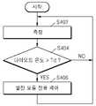
도 4는 본 발명의 일 실시예에 따른 운송 수단의 제어 방법을 나타낸 흐름도이다.4 is a flowchart illustrating a control method of a vehicle according to an embodiment of the present invention.
본 발명의 일 실시예에 따르면, 배터리 팩(110)이 동작하는 동안, 온도 검출부(240)는 다이오드(D1)의 온도를 측정한다(S402). 다이오드(D1)의 온도 측정은 계속적으로 수행되거나, 주기적으로 수행되는 등 다양한 형태로 수행될 수 있다.According to an embodiment of the present invention, while the
다이오드(D1)의 온도가 제1 기준 온도(Td)보다 큰 경우(S404), BMS(230)는 메인 제어부(140)에 발전 모듈(110)로부터 출력되는 충전 전류를 감소시키도록 요청할 수 있다(S406). 다른 예로서, 다이오드(D1)의 온도가 제1 기준 온도(Td)보다 큰 경우(S404), BMS(230)는 메인 제어부(140)에 다이오드(D1)의 온도 데이터를 제공하고, 메인 제어부(140)는 BMS(230)로부터 제공받은 다이오드(D1)의 온도 데이터에 따라 발전 모듈(110)로부터 공급되는 충전 전류를 조절할 수 있다.When the temperature of the diode D1 is greater than the first reference temperature Td (S404), the
도 5는 본 발명의 다른 실시예에 따른 배터리 팩(100b)의 구조를 나타낸 도면이다.5 is a view showing the structure of a
본 발명의 다른 실시예에 따른 배터리 팩(100b)은 배터리 셀(210), 다이오드(D1), 방전부(220), BMS(230), 온도 검출부(240), 및 바이패스부(410)를 포함할 수 있다.The
본 발명의 다른 실시예에 따르면, 다이오드(D1)와 바이패스부(410)가 제1 단자(P1)와 배터리 셀(210) 사이에 병렬로 연결되어, 배터리 셀의 충전 상태에 따라 바이패스부(410)를 연결시키거나 차단시킬 수 있다. 바이패스부(410)는 스위칭 소자를 포함하여 구성될 수 있다.According to another embodiment of the present invention, the diode D1 and the
BMS(230)는 배터리 팩(100b)이 동작하는 동안 배터리 셀(210)의 충전 상태를 측정한다. BMS(230)는 배터리 셀(210)의 충전 상태에 따라 제1 충전 경로(PATH1)를 통해 충전 전류를 도통시키거나, 제2 충전 경로(PATH2)를 통해 충전 전류를 도통시킨다.The
구체적으로, 배터리 셀(210)의 충전 상태가 기준 레벨 이하인 경우, BMS(230)는 바이패스부(410)의 스위칭 소자를 연결시켜 제1 충전 경로(PATH1)를 통해 충전 전류를 도통시킨다. 이로 인해 배터리 셀(210)의 충전 상태가 기준 레벨 이하이면, 다이오드(D1)를 통해서는 충전 전류가 거의 흐르지 않아, 다이오드(D1)에서 발열이 거의 발생하지 않게 된다.In detail, when the state of charge of the
배터리 셀(210)의 충전 상태가 기준 레벨을 초과하는 경우, BMS(230)는 바이패스부(410)의 스위칭 소자를 오프시켜, 제2 충전 경로(PATH2)를 통해 충전 전류를 도통시킨다. 이로 인해 배터리 셀(210)의 충전 상태가 기준 레벨을 초과하면, 다이오드(D1)를 통해 충전 전류를 공급받는다. 또한, BMS(230)는 제2 충전 경로(PATH2)를 통해 충전 전류를 도통시키는 경우, 온도 검출부(240)를 이용하여 다이오드(D1)의 온도를 모니터링하고, 다이오드(D1)의 온도가 제1 기준 온도 이상인 경우, 다이오드(D1)의 온도에 따라 발전 모듈(110)로부터 공급되는 충전 전류를 조절한다. 예를 들면, BMS(230)는 다이오드(D1)의 온도가 제1 기준 온도 이상인 경우, 발전 모듈(110)로부터 공급되는 충전 전류를 감소시키도록 메인 제어부(140)에 요청할 수 있다.When the state of charge of the
본 발명의 다른 실시예에 따르면, 배터리 셀(210)의 과충전이 문제되지 않는 충전 초기에는 다이오드(D1)를 통한 전압 강하를 수반하지 않고 바이패스부(410)를 통해 충전 전류를 공급받고, 배터리 셀(210)의 과충전이 문제되는 구간에서만 다이오드(D1)를 통해 충전 전류를 공급받아, 다이오드(D1)의 발열을 감소시키는 효과가 있다. 또한 본 발명의 다른 실시예에 따르면, 다이오드(D1)를 통해 충전 전류를 공급받는 동안에는 BMS(230)가 다이오드(D1)의 온도를 모니터링하고, 다이오드(D1)의 온도가 소정값 이상인 경우에 충전 전류를 감소시킴으로써, 다이오드(D1)의 발열로 인해 배터리 팩(100b)의 안정성이 저해되는 문제를 해결할 수 있다.According to another exemplary embodiment of the present invention, in the initial stage of charging in which overcharging of the
도 6은 본 발명의 다른 실시예에 따라, 시간에 따른 배터리 셀의 전압(Vbat), 다이오드 온도, 및 배터리 셀 온도의 변화를 나타낸 예시적인 그래프이다. 배터리 셀(210)의 전압(Vbat)은 배터리 셀(210)의 충전 상태(SOC)의 일례이다.6 is an exemplary graph illustrating a change in voltage Vbat, diode temperature, and battery cell temperature of a battery cell over time, according to another embodiment of the invention. The voltage Vbat of the
본 실시예에 따르면, 도 6과 같이 시간에 따라 배터리의 충전 상태가 만방전 상태로부터 만충전 상태로 변화하는 경우, 배터리 셀의 전압(Vbat)이 제1 기준값(Vref) 이하인 경우에는, 충전 전류를 제2 충전 경로(PATH2)를 통해 도통시키기 때문에, 다이오드(D1)의 온도는 거의 변화가 없고, 다이오드(D1)의 발열이 거의 없다. 배터리 셀의 전압(Vbat)이 제1 기준값(Vref)을 초과하는 경우, 충전 전류는 제1 충전 경로(PATH1)를 통해 도통되고, 다이오드(D1)의 온도가 상승하기 시작한다. 그런데 배터리 셀(210)의 충전 상태가 만충전 상태에 가까워짐에 따라, 다이오드(D1)를 통해 흐르는 충전 전류의 크기가 감소하여, 배터리 셀(210)의 충전 상태가 소정 상태 이상으로 가면, 다이오드(D1)에서 발열이 거의 발생하지 않고, 오히려 다이오드(D1)의 온도가 감소하기 시작한다. 이와 같이 본 발명의 다른 실시예에 따르면, 다이오드(D1)의 발열 자체가 감소하고, 다이오드(D1)에서 열이 발생하더라도 BMS(230)에서 다이오드(D1)의 온도에 따라 발전 모듈(110)로부터 공급되는 충전 전류를 조절하기 때문에, 다이오드(D1)의 발열로 인한 문제를 더욱 효과적으로 해결할 수 있다.According to the present exemplary embodiment, when the state of charge of the battery changes from the fully discharged state to the fully charged state as shown in FIG. 6, when the voltage Vbat of the battery cell is equal to or less than the first reference value Vref, the charging current Is conducted through the second charging path PATH2, the temperature of the diode D1 is almost unchanged, and there is little heat generation of the diode D1. When the voltage Vbat of the battery cell exceeds the first reference value Vref, the charging current is conducted through the first charging path PATH1, and the temperature of the diode D1 starts to rise. However, as the state of charge of the
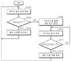
도 7은 본 발명의 다른 실시예에 따른 운송 수단의 제어 방법을 나타낸 흐름도이다.7 is a flowchart illustrating a control method of a vehicle according to another embodiment of the present invention.
본 발명의 다른 실시예에 따른 운송 수단의 제어 방법은, 배터리 팩(100b)이 동작하는 동안 배터리 셀(210)의 전압을 측정한다(S702).In the method of controlling a vehicle according to another exemplary embodiment of the present invention, the voltage of the
배터리 셀(210)의 전압(Vbat)이 제1 기준 전압(Vref) 이하인 경우(S704), 바이패스부(410)가 연결되어, 충전 전류가 제1 충전 경로(PATH1)를 통해 도통된다(S706).When the voltage Vbat of the
배터리 셀(210)의 전압(Vbat)이 제1 기준 전압(Vref)을 초과하는 경우(S704), 바이패스부(410)는 오프되고, 충전 전류는 제2 충전 경로(PATH2)를 통해 도통된다(S708). 이러한 경우, BMS(230)는 온도 측정부(240)를 이용하여 다이오드(D1)의 온도를 모니터링한다(S710). 다이오드(D1)의 온도가 제1 기준 온도(Td) 이상인 경우(S712), BMS(230)는 발전 모듈(110)로부터 공급되는 충전 전류를 감소시키도록 제어한다(S714).When the voltage Vbat of the
이제까지 본 발명에 대하여 바람직한 실시예를 중심으로 살펴보았다. 본 발명이 속하는 기술 분야에서 통상의 지식을 가진 자는 본 발명의 본질적인 특성에서 벗어나지 않는 범위에서 변형된 형태로 본 발명을 구현할 수 있음을 이해할 것이다. 그러므로 상기 개시된 실시예들은 한정적인 관점이 아니라 설명적인 관점에서 고려되어야 한다. 본 발명의 범위는 전술한 설명이 아니라 특허청구범위에 나타나 있으며, 특허청구범위에 의해 청구된 발명 및 청구된 발명과 균등한 발명들은 본 발명에 포함된 것으로 해석되어야 한다.The present invention has been described above with reference to preferred embodiments. It will be understood by those skilled in the art that the present invention may be embodied in various other forms without departing from the spirit or essential characteristics thereof. Therefore, the above-described embodiments should be considered in an illustrative rather than a restrictive sense. The scope of the present invention is defined by the appended claims rather than by the foregoing description, and the inventions claimed by the claims and the inventions equivalent to the claimed invention are to be construed as being included in the present invention.
10 운송 수단100, 100a, 100b 배터리 팩
110 발전 모듈120 스타터 모터
130 전기 부하140 메인 제어부
D1 다이오드210 배터리 셀
220 방전부230 배터리 제어부(BMS)
240 온도 검출부P1 제1 단자
P2 제2 단자P3 제3 단자
410 바이패스부PATH1 제1 충전 경로
PATH2 제2 충전 경로10
110
130
220
240 Temperature detector P1 first terminal
P2 Second Terminal P3 Third Terminal
410 bypass PATH1 first charging path
PATH2 Second charging path
Claims (18)
Translated fromKorean상기 배터리 팩은,
상기 발전 모듈로부터 충전 전류를 공급받아 전력을 충전하는 배터리 셀;
상기 발전 모듈과 상기 배터리 셀 사이에 직렬 연결되어 상기 충전 전류를 도통시키는 다이오드; 및
상기 다이오드의 온도에 따라 상기 발전 모듈로부터 공급되는 상기 충전 전류를 조절하는 제어부를 포함하는 운송 수단.As a vehicle comprising a power generation module and a battery pack for receiving the charging current generated from the power generation module to store electrical energy,
The battery pack (100)
A battery cell configured to charge power by receiving a charging current from the power generation module;
A diode connected in series between the power generation module and the battery cell to conduct the charging current; And
And a controller for adjusting the charging current supplied from the power generation module according to the temperature of the diode.
상기 다이오드의 온도를 측정하는 온도 검출부를 더 포함하는 운송 수단.The method of claim 1,
And a temperature detector for measuring the temperature of the diode.
상기 배터리 셀은 리튬-이온 배터리 셀인, 운송 수단.The method of claim 1,
The battery cell is a lithium-ion battery cell.
상기 발전 모듈의 출력 전압은 상기 리튬-이온 배터리 셀의 정격 전압보다 높고,
상기 다이오드는 상기 발전 모듈의 출력 전압과 상기 리튬-이온 배터리 셀의 정격 전압의 전압 차에 대응하는 전압 강하를 수반하는, 운송 수단.The method of claim 3,
The output voltage of the power generation module is higher than the rated voltage of the lithium-ion battery cell,
The diode carries a voltage drop corresponding to a voltage difference between an output voltage of the power generation module and a rated voltage of the lithium-ion battery cell.
상기 제어부는 상기 다이오드의 온도가 제1 기준 온도 이상이면 상기 발전 모듈로부터 공급되는 충전 전류를 감소시키는, 운송 수단.The method of claim 1,
And the control unit reduces the charging current supplied from the power generation module when the temperature of the diode is equal to or greater than a first reference temperature.
엔진; 및
상기 엔진으로부터 공급되는 에너지로부터 전기 에너지를 생성하는 발전 모듈을 더 포함하는, 운송 수단.The method of claim 1,
engine; And
And a power generation module for generating electrical energy from energy supplied from the engine.
상기 운송 수단의 엔진 시동을 위한 시동 동력을 제공하고, 상기 배터리 셀로부터 방전 전류를 공급받는 스타터 모터를 더 포함하는, 운송 수단.The method according to claim 6,
And a starter motor providing starting power for starting the engine of the vehicle and receiving discharge current from the battery cell.
상기 운송 수단은 상기 발전 모듈과 상기 배터리 셀 사이에서, 상기 다이오드와 병렬로 연결되는 스위치를 구비하는 바이패스부를 더 포함하고,
상기 제어부는, 상기 배터리 셀의 충전 상태가 제1 기준값 이하이면 상기 바이패스부를 도통시키고, 상기 제1 기준값을 초과하면 상기 바이패스부를 차단시키는, 운송 수단.The method of claim 1,
The vehicle further includes a bypass unit having a switch connected in parallel with the diode between the power generation module and the battery cell.
And the control unit conducts the bypass unit when the state of charge of the battery cell is equal to or less than a first reference value, and blocks the bypass unit when the battery cell exceeds the first reference value.
상기 제어부는, 상기 배터리 셀의 충전 상태가 상기 제1 기준값을 초과하는 경우에만 상기 다이오드의 온도에 따라 상기 발전 모듈로부터 공급되는 충전 전류를 조절하는, 운송 수단.9. The method of claim 8,
And the control unit adjusts the charging current supplied from the power generation module according to the temperature of the diode only when the state of charge of the battery cell exceeds the first reference value.
상기 발전 모듈과 상기 배터리 셀 사이에서, 상기 다이오드와 병렬로 연결되고, 상기 배터리 셀로부터 출력되는 방전 전류를 도통시키는 방전부를 더 포함하는, 운송 수단.The method of claim 1,
And a discharge unit connected in parallel with the diode between the power generation module and the battery cell and conducting a discharge current output from the battery cell.
상기 운송 수단은 상기 배터리 팩에 포함된 다이오드를 통해 상기 발전 모듈로부터 배터리 셀로 충전 전류를 공급하고, 상기 운송 수단의 제어 방법은,
상기 다이오드의 온도를 측정하는 단계; 및
상기 다이오드의 온도에 따라 상기 발전 모듈로부터 공급되는 상기 충전 전류를 조절하는 단계를 포함하는, 운송 수단의 제어 방법.In the control method of the vehicle comprising a power generation module and a battery pack for receiving the charging current generated from the power generation module to store electrical energy,
The vehicle supplies a charging current from the power generation module to the battery cell through a diode included in the battery pack, the control method of the vehicle,
Measuring the temperature of the diode; And
Adjusting the charging current supplied from the power generation module according to the temperature of the diode.
상기 배터리 셀은 리튬-이온 배터리 셀인, 운송 수단의 제어 방법.12. The method of claim 11,
And said battery cell is a lithium-ion battery cell.
상기 발전 모듈의 출력 전압은 상기 리튬-이온 배터리 셀의 정격 전압보다 높고,
상기 다이오드는 상기 발전 모듈의 출력 전압과 상기 리튬-이온 배터리 셀의 정격 전압의 전압 차에 대응하는 전압 강하를 수반하는, 운송 수단의 제어 방법.The method of claim 12,
The output voltage of the power generation module is higher than the rated voltage of the lithium-ion battery cell,
And the diode carries a voltage drop corresponding to the voltage difference between the output voltage of the power generation module and the rated voltage of the lithium-ion battery cell.
상기 발전 모듈로부터 공급되는 충전 전류를 조절하는 단계는, 상기 다이오드 온도가 제1 기준 온도 이상이면 상기 발전 모듈로부터 공급되는 충전 전류를 감소시키도록 조절하는, 운송 수단의 제어 방법.12. The method of claim 11,
And adjusting the charging current supplied from the power generation module to adjust to reduce the charging current supplied from the power generation module when the diode temperature is equal to or greater than a first reference temperature.
상기 발전 모듈은 상기 운송 수단의 엔진으로부터 공급되는 에너지로부터 전기 에너지를 생성하고,
상기 발전 모듈로부터 공급되는 충전 전류를 조절하는 단계는, 상기 운송 수단의 메인 제어부에 의해 수행되는, 운송 수단의 제어 방법.12. The method of claim 11,
The power generation module generates electrical energy from energy supplied from an engine of the vehicle,
Adjusting the charging current supplied from the power generation module is performed by a main controller of the vehicle.
상기 배터리 셀은 상기 운송 수단의 엔진 시동을 위한 시동 동력을 제공하는 스타터 모터에 방전 전류를 공급하는, 운송 수단의 제어 방법.16. The method of claim 15,
And the battery cell supplies a discharge current to a starter motor that provides starting power for starting the engine of the vehicle.
상기 배터리 셀의 충전 상태를 감지하는 단계;
상기 배터리 셀의 충전 상태가 제1 기준값 이하이면, 상기 충전 전류를 상기 다이오드와 병렬 연결된 바이패스 경로로 바이패스시키는 단계; 및
상기 배터리 셀의 충전 상태가 상기 제1 기준값을 초과하면, 상기 바이패스 경로를 차단하는 단계를 더 포함하는, 운송 수단의 제어 방법.12. The method of claim 11,
Detecting a state of charge of the battery cell;
Bypassing the charging current through a bypass path connected in parallel with the diode when the state of charge of the battery cell is equal to or less than a first reference value; And
Blocking the bypass path if the state of charge of the battery cell exceeds the first reference value.
상기 발전 모듈로부터 공급되는 충전 전류를 조절하는 단계는, 상기 배터리 셀의 충전 상태가 상기 제1 기준값을 초과하는 경우에만 수행되는, 운송 수단의 제어 방법.18. The method of claim 17,
Adjusting the charging current supplied from the power generation module is performed only when the state of charge of the battery cell exceeds the first reference value.
Priority Applications (4)
| Application Number | Priority Date | Filing Date | Title |
|---|---|---|---|
| KR1020120030236AKR101312263B1 (en) | 2012-03-23 | 2012-03-23 | Vehicle and method for controlling the same |
| US13/615,088US20130249493A1 (en) | 2012-03-23 | 2012-09-13 | Vehicle and method of controlling the same |
| JP2013037616AJP2013201889A (en) | 2012-03-23 | 2013-02-27 | Vehicle and method of controlling the same |
| CN2013100905216ACN103318045A (en) | 2012-03-23 | 2013-03-20 | Vehicle and method of controlling the same |
Applications Claiming Priority (1)
| Application Number | Priority Date | Filing Date | Title |
|---|---|---|---|
| KR1020120030236AKR101312263B1 (en) | 2012-03-23 | 2012-03-23 | Vehicle and method for controlling the same |
Publications (1)
| Publication Number | Publication Date |
|---|---|
| KR101312263B1true KR101312263B1 (en) | 2013-09-25 |
Family
ID=49187204
Family Applications (1)
| Application Number | Title | Priority Date | Filing Date |
|---|---|---|---|
| KR1020120030236AExpired - Fee RelatedKR101312263B1 (en) | 2012-03-23 | 2012-03-23 | Vehicle and method for controlling the same |
Country Status (4)
| Country | Link |
|---|---|
| US (1) | US20130249493A1 (en) |
| JP (1) | JP2013201889A (en) |
| KR (1) | KR101312263B1 (en) |
| CN (1) | CN103318045A (en) |
Cited By (2)
| Publication number | Priority date | Publication date | Assignee | Title |
|---|---|---|---|---|
| KR20210046974A (en)* | 2019-10-21 | 2021-04-29 | 에스케이이노베이션 주식회사 | System and method for protecting relays |
| CN113978311A (en)* | 2021-10-15 | 2022-01-28 | 潍柴动力股份有限公司 | A battery temperature correction method, device and electronic device |
Families Citing this family (10)
| Publication number | Priority date | Publication date | Assignee | Title |
|---|---|---|---|---|
| EP2645527A1 (en)* | 2012-03-26 | 2013-10-02 | Samsung SDI Co., Ltd. | Battery pack |
| US9318910B2 (en)* | 2012-09-06 | 2016-04-19 | Samsung Sdi Co., Ltd. | Cell balancing circuit and cell balancing method using the same |
| DE102016214484A1 (en)* | 2016-08-04 | 2018-02-08 | Audi Ag | Method for preparing a battery of a motor vehicle for a transport and motor vehicle |
| US10322688B2 (en) | 2016-12-30 | 2019-06-18 | Textron Innovations Inc. | Controlling electrical access to a lithium battery on a utility vehicle |
| US10391864B2 (en)* | 2017-02-08 | 2019-08-27 | Toyota Motor Engineering & Manufacturing North America, Inc. | System to balance high voltage battery for vehicle |
| US10195948B2 (en)* | 2017-03-07 | 2019-02-05 | Textron Innovations Inc. | Controlling charge on a lithium battery of a utility vehicle |
| DE102018218596B4 (en)* | 2018-10-30 | 2020-06-04 | Conti Temic Microelectronic Gmbh | Method for charging a starter battery and charging device for charging a starter battery |
| JP7420224B2 (en)* | 2020-03-26 | 2024-01-23 | 株式会社村田製作所 | Energy storage devices, electric vehicles and power systems |
| CN112994191B (en)* | 2021-04-30 | 2021-09-24 | 深圳市永联科技股份有限公司 | Current control unit, power supply unit and vehicle |
| CN114123374A (en)* | 2021-09-30 | 2022-03-01 | 岚图汽车科技有限公司 | A power battery voltage control method and related equipment |
Citations (2)
| Publication number | Priority date | Publication date | Assignee | Title |
|---|---|---|---|---|
| JP2009177903A (en)* | 2008-01-23 | 2009-08-06 | Denso Corp | Vehicle system |
| JP2011217549A (en)* | 2010-04-01 | 2011-10-27 | Hitachi Automotive Systems Ltd | Battery charge controller |
Family Cites Families (14)
| Publication number | Priority date | Publication date | Assignee | Title |
|---|---|---|---|---|
| JPH05182696A (en)* | 1991-12-27 | 1993-07-23 | Japan Storage Battery Co Ltd | Charge control device for storage battery |
| EP0644642A3 (en)* | 1993-07-30 | 1995-05-24 | Texas Instruments Inc | Improvements in or relating to power sources. |
| JPH07222370A (en)* | 1994-01-28 | 1995-08-18 | Sanyo Electric Co Ltd | Charger with temperature sensor |
| JPH08126222A (en)* | 1994-10-28 | 1996-05-17 | Yamaha Motor Co Ltd | Charger |
| JP3845261B2 (en)* | 2001-02-28 | 2006-11-15 | 矢崎総業株式会社 | Electric load drive controller for automobile |
| JP4329326B2 (en)* | 2002-10-30 | 2009-09-09 | パナソニック株式会社 | Secondary battery and secondary battery pack with temperature protection element unit |
| JP4121511B2 (en)* | 2004-03-30 | 2008-07-23 | 三洋電機株式会社 | Power supply |
| JP4816552B2 (en)* | 2007-04-12 | 2011-11-16 | 株式会社デンソー | Disconnection detection device and control system |
| US8080900B2 (en)* | 2007-07-18 | 2011-12-20 | Exaflop Llc | Direct-coupled IT load |
| JP2010035371A (en)* | 2008-07-30 | 2010-02-12 | Kokusan Denki Co Ltd | Battery charging apparatus |
| CN102246386B (en)* | 2008-12-09 | 2014-06-11 | 丰田自动车株式会社 | Vehicle Power System |
| CN201556966U (en)* | 2009-06-10 | 2010-08-18 | 上海攀业氢能源科技有限公司 | A backup power system composed of a modular fuel cell and an energy storage battery |
| JP5359604B2 (en)* | 2009-06-26 | 2013-12-04 | 株式会社デンソー | Control device for power conversion circuit |
| JP2011223755A (en)* | 2010-04-09 | 2011-11-04 | Honda Motor Co Ltd | DC-DC converter |
- 2012
- 2012-03-23KRKR1020120030236Apatent/KR101312263B1/ennot_activeExpired - Fee Related
- 2012-09-13USUS13/615,088patent/US20130249493A1/ennot_activeAbandoned
- 2013
- 2013-02-27JPJP2013037616Apatent/JP2013201889A/enactivePending
- 2013-03-20CNCN2013100905216Apatent/CN103318045A/enactivePending
Patent Citations (2)
| Publication number | Priority date | Publication date | Assignee | Title |
|---|---|---|---|---|
| JP2009177903A (en)* | 2008-01-23 | 2009-08-06 | Denso Corp | Vehicle system |
| JP2011217549A (en)* | 2010-04-01 | 2011-10-27 | Hitachi Automotive Systems Ltd | Battery charge controller |
Cited By (4)
| Publication number | Priority date | Publication date | Assignee | Title |
|---|---|---|---|---|
| KR20210046974A (en)* | 2019-10-21 | 2021-04-29 | 에스케이이노베이션 주식회사 | System and method for protecting relays |
| KR102780655B1 (en)* | 2019-10-21 | 2025-03-12 | 에스케이온 주식회사 | System and method for protecting relays |
| CN113978311A (en)* | 2021-10-15 | 2022-01-28 | 潍柴动力股份有限公司 | A battery temperature correction method, device and electronic device |
| CN113978311B (en)* | 2021-10-15 | 2024-05-17 | 潍柴动力股份有限公司 | Battery temperature correction method, device and electronic equipment |
Also Published As
| Publication number | Publication date |
|---|---|
| US20130249493A1 (en) | 2013-09-26 |
| CN103318045A (en) | 2013-09-25 |
| JP2013201889A (en) | 2013-10-03 |
Similar Documents
| Publication | Publication Date | Title |
|---|---|---|
| KR101312263B1 (en) | Vehicle and method for controlling the same | |
| KR101397023B1 (en) | Battery pack and method for controlling the same | |
| KR102016752B1 (en) | Battery pack and method for controlling the same | |
| KR101420340B1 (en) | Vehicle operating system and method for controlling the same | |
| KR101074785B1 (en) | Energy storage systems, including battery management systems and control methods thereof, and battery management systems | |
| US8085051B2 (en) | Abnormality detecting device for storage element, abnormality detecting method for storage element, abnormality detecting program for storage element, and computer-readable recording medium storing abnormality detecting program | |
| US9263900B2 (en) | Battery pack including a battery management system configured to control charging and discharging thereof | |
| EP2645467A1 (en) | Battery pack charging system and method of controlling the same | |
| US11063447B2 (en) | Battery pack and energy storage system comprising same | |
| JP3931446B2 (en) | Battery charge state adjustment device | |
| JP2014006251A (en) | Battery pack, and soc algorithm applied to battery pack | |
| KR101342602B1 (en) | Battery pack | |
| JP2003092805A (en) | Power supply unit for hybrid car | |
| WO2013008814A1 (en) | Power supply device and vehicle equipped with power supply device | |
| KR102020044B1 (en) | Battery charging system, and method for controlling maximum capacity charging in battery module using the same | |
| KR20160067600A (en) | Apparatus and method for protecting overcharge of battery cell | |
| KR20220090206A (en) | Device and method for preventing battery abnormalities using diodes | |
| JP7004385B2 (en) | Management device and power supply system |
Legal Events
| Date | Code | Title | Description |
|---|---|---|---|
| A201 | Request for examination | ||
| PA0109 | Patent application | St.27 status event code:A-0-1-A10-A12-nap-PA0109 | |
| PA0201 | Request for examination | St.27 status event code:A-1-2-D10-D11-exm-PA0201 | |
| D13-X000 | Search requested | St.27 status event code:A-1-2-D10-D13-srh-X000 | |
| D14-X000 | Search report completed | St.27 status event code:A-1-2-D10-D14-srh-X000 | |
| E902 | Notification of reason for refusal | ||
| PE0902 | Notice of grounds for rejection | St.27 status event code:A-1-2-D10-D21-exm-PE0902 | |
| P11-X000 | Amendment of application requested | St.27 status event code:A-2-2-P10-P11-nap-X000 | |
| P13-X000 | Application amended | St.27 status event code:A-2-2-P10-P13-nap-X000 | |
| E701 | Decision to grant or registration of patent right | ||
| PE0701 | Decision of registration | St.27 status event code:A-1-2-D10-D22-exm-PE0701 | |
| GRNT | Written decision to grant | ||
| PR0701 | Registration of establishment | St.27 status event code:A-2-4-F10-F11-exm-PR0701 | |
| PR1002 | Payment of registration fee | St.27 status event code:A-2-2-U10-U11-oth-PR1002 Fee payment year number:1 | |
| PG1601 | Publication of registration | St.27 status event code:A-4-4-Q10-Q13-nap-PG1601 | |
| R18-X000 | Changes to party contact information recorded | St.27 status event code:A-5-5-R10-R18-oth-X000 | |
| LAPS | Lapse due to unpaid annual fee | ||
| PC1903 | Unpaid annual fee | St.27 status event code:A-4-4-U10-U13-oth-PC1903 Not in force date:20160914 Payment event data comment text:Termination Category : DEFAULT_OF_REGISTRATION_FEE | |
| PC1903 | Unpaid annual fee | St.27 status event code:N-4-6-H10-H13-oth-PC1903 Ip right cessation event data comment text:Termination Category : DEFAULT_OF_REGISTRATION_FEE Not in force date:20160914 | |
| R18-X000 | Changes to party contact information recorded | St.27 status event code:A-5-5-R10-R18-oth-X000 |