KR101311896B1 - Displacement adjustment method of stereoscopic image and stereoscopic image device applying the same - Google Patents
Displacement adjustment method of stereoscopic image and stereoscopic image device applying the sameDownload PDFInfo
- Publication number
- KR101311896B1 KR101311896B1KR1020060112298AKR20060112298AKR101311896B1KR 101311896 B1KR101311896 B1KR 101311896B1KR 1020060112298 AKR1020060112298 AKR 1020060112298AKR 20060112298 AKR20060112298 AKR 20060112298AKR 101311896 B1KR101311896 B1KR 101311896B1
- Authority
- KR
- South Korea
- Prior art keywords
- displacement
- range
- sum
- convolution
- amount
- Prior art date
- Legal status (The legal status is an assumption and is not a legal conclusion. Google has not performed a legal analysis and makes no representation as to the accuracy of the status listed.)
- Expired - Fee Related
Links
Images


Classifications
- H—ELECTRICITY
- H04—ELECTRIC COMMUNICATION TECHNIQUE
- H04N—PICTORIAL COMMUNICATION, e.g. TELEVISION
- H04N13/00—Stereoscopic video systems; Multi-view video systems; Details thereof
- H04N13/10—Processing, recording or transmission of stereoscopic or multi-view image signals
- H04N13/106—Processing image signals
- H04N13/128—Adjusting depth or disparity
- H—ELECTRICITY
- H04—ELECTRIC COMMUNICATION TECHNIQUE
- H04N—PICTORIAL COMMUNICATION, e.g. TELEVISION
- H04N13/00—Stereoscopic video systems; Multi-view video systems; Details thereof
- H04N13/10—Processing, recording or transmission of stereoscopic or multi-view image signals
- H04N13/106—Processing image signals
- H04N13/144—Processing image signals for flicker reduction
- H—ELECTRICITY
- H04—ELECTRIC COMMUNICATION TECHNIQUE
- H04N—PICTORIAL COMMUNICATION, e.g. TELEVISION
- H04N2213/00—Details of stereoscopic systems
- H04N2213/002—Eyestrain reduction by processing stereoscopic signals or controlling stereoscopic devices
Landscapes
- Engineering & Computer Science (AREA)
- Multimedia (AREA)
- Signal Processing (AREA)
- Testing, Inspecting, Measuring Of Stereoscopic Televisions And Televisions (AREA)
Abstract
Translated fromKoreanDescription
Translated fromKorean도 1은 일반적인 양안시차의 종류를 도시한 도면,1 is a diagram illustrating a type of a general binocular parallax;
도 2는 종래의 입체 카메라의 종류를 도시한 도면,2 is a view showing the type of a conventional stereoscopic camera,
도 3은 본 발명의 일 실시예에 따른 입체 영상장치가 적용된 입체 카메라 시스템의 블록도,3 is a block diagram of a stereoscopic camera system to which a stereoscopic imaging apparatus according to an embodiment of the present invention is applied;
도 4는 본 발명의 일 실시예에 따른 변위 추정에 의해 산출된 변위 히스토그램을 도시한 도면,4 is a diagram showing a displacement histogram calculated by displacement estimation according to an embodiment of the present invention;
도 5는 본 발명의 일 실시예에 따른 양안시차에 따른 깊이감의 범위를 산출하는 방법을 설명하기 위한 도면,5 is a view for explaining a method for calculating a range of depth according to binocular parallax according to an embodiment of the present invention;
도 6a는 본 발명의 일 실시예에 따른 컨벌루션 마스크를 도시한 도면,6A illustrates a convolution mask according to an embodiment of the present invention;
도 6b는 본 발명의 다른 실시예에 따른 컨벌루션 마스크를 도시한 도면,6B illustrates a convolution mask according to another embodiment of the present invention;
도 7은 도 6a의 컨벌루션 마스크를 이용하여 변위 히스토그램 에너지 분석을 설명하기 위한 도면,7 is a view for explaining a displacement histogram energy analysis using the convolution mask of FIG. 6A;
도 8은 도 7의 변위 히스토그램 에너지 분석을 이용하여 변위 조정량을 결정하는 방법을 설명하기 위한 도면,8 is a view for explaining a method of determining a displacement adjustment amount using the displacement histogram energy analysis of FIG. 7;
도 9는 도 8의 변위 조정량에 따라 입체 영상을 재생성하는 방법을 설명하기 위한 도면, 그리고9 is a view for explaining a method of reproducing a stereoscopic image according to the displacement adjustment amount of FIG. 8; and
도 10은 본 발명의 일 실시예에 따른 입체 영상장치의 입체 영상의 변위 조정방법의 설명에 제공되는 흐름도이다.10 is a flowchart provided to explain a method for adjusting displacement of a stereoscopic image of the stereoscopic image apparatus according to the exemplary embodiment of the present invention.
* 도면의 주요 부분에 대한 부호의 설명 *Explanation of symbols on the main parts of the drawings
200 : 입체 카메라 300 : 입체 영상장치200: stereoscopic camera 300: stereoscopic image device
310 : 입력부 320 : 좌영상 버퍼310: input unit 320: left image buffer
325 : 우영상 버퍼 330 : 변위 추정부325: right image buffer 330: displacement estimation unit
340 : 변위 조정부 350 : 입체 영상 재생성부340: displacement adjustment unit 350: stereoscopic image reproduction unit
360 : 지터 제거부 370 : 디스플레이부360: jitter removing unit 370: display unit
본 발명은 입체 영상의 변위 조정방법 및 이를 적용한 입체 영상장치에 관한 것으로, 더욱 상세하게는, 입체 영상 시청시 발생하는 시각 피로도를 줄이기 위해 입체 영상의 변위를 조정하는 입체 영상의 변위 조정방법 및 이를 적용한 입체 영상장치에 관한 것이다.The present invention relates to a method of adjusting a displacement of a stereoscopic image and a stereoscopic apparatus using the same, and more particularly, to a displacement adjustment method of a stereoscopic image for adjusting the displacement of a stereoscopic image in order to reduce visual fatigue generated when viewing a stereoscopic image. The present invention relates to an applied stereoscopic imaging apparatus.
일반적으로, 스테레오 카메라 또는 다시점 카메라와 같은 입체 카메라는 사람의 눈과 같이 2대 이상의 카메라를 사용하여 좌, 우의 영상을 얻고, 그 두 영상 사이의 거리 즉, 변위(disparity)에 의해 시청자로 하여금 영상에 입체감을 느끼게 한다. 구체적으로, 입체 카메라에 의해 촬상된 두 영상 사이의 변위로 인해 사용자는 두 눈 사이에 시차(parallax)를 느끼게 되고, 이러한 양안시차는 입체감을 느끼게 한다. 즉, 변위와 시차는 상관관계를 가진다.In general, a stereo camera such as a stereo camera or a multi-view camera uses two or more cameras, such as a human eye, to obtain left and right images, and the viewer is caused by the distance between the two images, that is, the disparity. Makes the image feel three-dimensional. In detail, the user may feel a parallax between the two eyes due to the displacement between the two images captured by the stereoscopic camera, and the binocular parallax may cause a three-dimensional feeling. That is, displacement and parallax have a correlation.
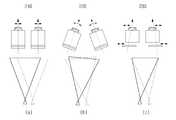
도 1은 일반적인 양안시차의 종류를 도시한 도면이다. 도 1를 참조하면, 입체 영상 시청시 사용자가 느끼는 양안시차는 (a)음의 시차, (b)양의 시차, 및 (c)제로 시차로 세가지가 있다. 구체적으로, (a)음의 시차는 영상에 포함된 오브젝트가 스크린으로부터 튀어 나온 것처럼 보이는 경우이다. 그리고, (b)양의 시차는 오브젝트가 스크린 속으로 들어간 것처럼 보이는 경우이며, (c)제로 시차는 오브젝트가 스크린과 동일한 깊이로 보이는 경우이다.1 is a diagram illustrating a type of general binocular disparity. Referring to FIG. 1, there are three binocular disparities felt by a user when viewing a stereoscopic image, such as (a) negative parallax, (b) positive parallax, and (c) zero parallax. Specifically, (a) the sound parallax is when the object included in the image appears to protrude from the screen. And (b) positive parallax is a case where the object appears to enter the screen, (c) a zero parallax is a case where the object appears to the same depth as the screen.
일반적으로, 입체 영상에서 음의 시차가 양의 시차보다 입체 효과가 더 크지만, 양안의 수렴각이 음의 시차에서 양의 시차일 때보다 크기 대문에 양안의 편안함은 양의 시차가 더 크다. 그러나, 양의 시차가 편안하더라도 입체 영상 내에 오브젝트들이 양의 시차만을 가지면 양안은 피로감을 느끼게 된다. 마찬가지로, 입체 영상 내에 오브젝트들이 음의 시차만을 가져도 양안은 피로감을 느끼게 된다.In general, although the negative parallax is larger in stereoscopic effect than the positive parallax in the stereoscopic image, the comfort of both eyes is larger because the convergence angle of the binocular is larger than the positive parallax in the negative parallax. However, even if the positive parallax is comfortable, both eyes feel fatigue when the objects in the stereoscopic image have only positive parallax. Similarly, both eyes feel fatigue even when objects in the stereoscopic image have only negative parallax.
도 2는 종래의 입체 카메라의 종류를 도시한 도면이다. 도 2를 참조하면, 종래의 입체 카메라로는 (a)평행형 입체 카메라(210), (b)교차(toe-in)형 입체 카메라(220), 및 (c)이종(hybrid)형 입체 카메라(230) 등이 있다.2 is a view showing the type of a conventional stereoscopic camera. Referring to FIG. 2, a conventional stereoscopic camera includes (a) a parallel
그런데, 평행형 입체 카메라(210)는 평행하게 배치되어 영상 압축/전송, 및 영상 처리에는 유리하지만, 사람의 눈처럼 한 점에 모아지는 수렴(convergence) 기능이 없다. 교차형 입체 카메라(220)의 경우에는 수렴 기능은 있으나, 입체 영상의 좌우 끝단에서 수직 시차가 발생하였다. 수직 시차로 인한 입체 영상의 왜곡은 시각의 피로감을 발생시켰다. 그리고, 이종형 입체 카메라(230)는 렌즈와 CCD를 분리하여 이동시킴으로써, 수직 시차없이 수렴 기능을 조절하여 시각의 피로감이 적은 입체 영상을 구현할 수 있다.By the way, the parallel
그러나, 다시점 카메라의 경우에는 이종형 입체 카메라(230)와 같은 기능을 구현하는 것이 어려울 뿐만 아니라, 다른 입체 카메라의 경우에는 마찬가지이다.However, in the case of a multi-view camera, not only it is difficult to implement the same function as the heterogeneous
따라서, 다시점 카메라와 같은 다른 입체 카메라로 촬상한 입체 영상도 이종형 입체 카메라(230)로 촬상한 입체 영상처럼 디스플레이하기 위한 방법이 요구된다.Therefore, there is a need for a method for displaying a stereoscopic image captured by another stereoscopic camera such as a multiview camera as a stereoscopic image captured by the heterogeneous
따라서, 본 발명의 목적은, 안정적이고 피로감이 적은 최적의 입체 영상을 제공하기 위한 입체 영상의 변위 조정방법 및 이를 적용한 입체 영상장치를 제공함에 있다.Accordingly, an object of the present invention is to provide a method for adjusting displacement of a stereoscopic image and a stereoscopic imaging apparatus using the same to provide an optimal stereoscopic image with stable and low fatigue.
그리고, 본 발명의 다른 목적은, 평행형 또는 다시점 카메라로 촬상한 입체 영상을 이종형 입체 카메라로 촬상한 입체 영상처럼 구현하기 위한 입체 영상의 변위 조정방법 및 이를 적용한 입체 영상장치를 제공함에 있다.Another object of the present invention is to provide a stereoscopic image displacement adjustment method and a stereoscopic imaging apparatus using the same to implement a stereoscopic image captured by a parallel or multi-view camera as a stereoscopic image captured by a heterogeneous stereoscopic camera.
상기 목적을 달성하기 위한 본 발명에 따른 입체 영상의 변위 조정방법은 입력되는 입체 영상의 변위를 추정하여 픽셀 단위의 변위 히스토그램을 산출하는 단계, 상기 변위 히스토그램의 소정 시차 범위의 에너지를 분석하여 변위 조정량을 산출하는 단계, 및 상기 변위 조정량에 따라 상기 입체 영상을 재생성하는 단계를 포함한다.Displacement adjustment method of a stereoscopic image according to the present invention for achieving the above object is to calculate a displacement histogram in units of pixels by estimating the displacement of the input stereoscopic image, the displacement adjustment by analyzing the energy of a predetermined parallax range of the displacement histogram Calculating an amount, and reproducing the stereoscopic image according to the displacement adjustment amount.
이때, 상기 변위 조정량 산출 단계는, 상기 변위 히스토그램의 소정 시차 범위에서 변위 에너지가 가장 높은 범위의 이동량을 상기 변위 조정량으로 결정하는 것이 바람직하다.At this time, the displacement adjustment amount calculating step, it is preferable to determine the movement amount of the range of the highest displacement energy in the predetermined parallax range of the displacement histogram as the displacement adjustment amount.
보다 구체적으로, 상기 소정 시차 범위는, 상기 소정 시차 범위는, 융합한계 ±7도 이내의 어느 범위인 것이 바람직하다.More specifically, it is preferable that the said predetermined parallax range is any range within +/- 7 degree of a fusion limit.
그리고, 상기 소정 시차 범위가 양안시차의 범위 ±1도의 범위 및 양안시차의 범위 ±2도의 범위이면, ±1도의 범위일 때의 컨벌루션 마스크와 변위 히스토그램의 컨벌루션 합이 최대가 되는 이동량 및 및 ±2도의 범위일 때의 컨벌루션 마스크와 변위 히스토그램의 컨벌루션 합이 최대가 되는 이동량의 절대값의 차가 임계값 이하이면, ±1도의 범위에 해당하는 변위 히스토그램의 이동량을 상기 변위 조정량으로 결정하는 것이 바람직하다.If the predetermined parallax range is in the range of ± 1 degree of binocular parallax and in the range of ± 2 degree of binocular parallax, the amount of movement where the convolution sum of the convolution mask and the displacement histogram when the range of ± 1 degree is maximum, and ± 2 If the difference between the absolute value of the amount of movement where the convolutional sum of the convolution mask and the displacement histogram is the maximum in the range of degrees is less than or equal to the threshold, it is preferable to determine the amount of movement of the displacement histogram corresponding to the range of ± 1 degree as the displacement adjustment amount. .
또는, ±1도의 범위일 때의 컨벌루션 마스크와 변위 히스토그램의 컨벌루션 합이 최대가 되는 이동량 및 ±2도의 범위일 때의 컨벌루션 마스크와 변위 히스토그램의 컨벌루션 합이 최대가 되는 이동량의 절대값의 차가 임계값보다 크고, ±1도의 범위에서 컨벌루션 합이 최대가 되는 만큼 이동했을 때 ±2도의 범위 이외의 영역에서의 변위 합이 ±2도에서 컨벌루션 합이 최대가 되는 만큼 이동했을 때 ±2도의 범위 이외의 영역에서의 변위 합보다 작으면, ±1도의 범위에 해당하는 이동량을 상기 변위 조정량으로 결정하는 것이 바람 직하다.Alternatively, the difference between the absolute value of the amount of movement where the convolutional sum of the convolutional mask and the displacement histogram becomes the maximum in the range of ± 1 degree and the amount of the maximum amount of the convolutional sum of the convolutional mask and the displacement histogram in the range of ± 2 degrees is the threshold. If the sum of displacements in an area outside the range of ± 2 degrees is greater than the maximum convolution sum in the range of ± 1 degrees, the deviation sum outside the range of ± 2 degrees is moved outside the range of ± 2 degrees when the convolution sum is maximized at ± 2 degrees. If it is smaller than the sum of displacements in the area, it is preferable to determine the displacement amount corresponding to the range of ± 1 degree as the displacement adjustment amount.
또는, ±1도의 범위일 때의 컨벌루션 마스크와 변위 히스토그램의 컨벌루션 합이 최대가 되는 이동량 및 ±2도의 범위일 때의 컨벌루션 마스크와 변위 히스토그램의 컨벌루션 합이 최대가 되는 이동량의 절대값의 차가 임계값보다 크고, ±1도의 범위에서 컨벌루션 합이 최대가 되는 만큼 이동했을 때 ±2도의 범위 이외의 영역에서의 변위 합이 ±2도의 범위에서 컨벌루션 합이 최대가 되는 만큼 이동했을 때 ±2도의 범위 이외의 영역에서의 변위 합보다 크면, ±2도 이내의 범위에 해당하는 이동량을 상기 변위 조정량으로 결정하는 것이 바람직하다.Alternatively, the difference between the absolute value of the amount of movement where the convolutional sum of the convolutional mask and the displacement histogram becomes the maximum in the range of ± 1 degree and the amount of the maximum amount of the convolutional sum of the convolutional mask and the displacement histogram in the range of ± 2 degrees is the threshold. If the sum of displacements in an area outside the range of ± 2 degrees is greater than the maximum convolution sum in the range of ± 1 degrees, the deviation sum outside the range of ± 2 degrees is outside the range of ± 2 degrees when the sum of the convolution sums is moved in the range of ± 2 degrees. When larger than the sum of the displacements in the region of, it is preferable to determine the displacement amount corresponding to the range within ± 2 degrees as the displacement adjustment amount.
그리고, 상기 소정 시차 범위 및 상기 임계값은 실험치인 것이 바람직하다.The predetermined parallax range and the threshold are preferably experimental values.
바람직하게는, 상기 입체 영상 재생성 단계는, 상기 입력되는 입체 영상의 좌 영상을 상기 변위 조정량의 절반만큼 클로핑하는 단계, 상기 입력되는 입체 영상의 우 영상을 상기 변위 조정량의 절반만큼 클로핑하는 단계, 및 상기 클로핑된 좌 영상 및 우 영상을 겹치는 단계를 포함한다.Preferably, the reproducing of the stereoscopic image comprises: clipping the left image of the input stereoscopic image by half of the displacement adjustment amount, and clipping the right image of the input stereoscopic image by half of the displacement adjustment amount. And overlapping the clipped left and right images.
또한, 상기 재생성된 입체 영상에 MA(Moving Average) 필터링을 적용하여 지터를 제거하는 단계를 더 포함하는 것이 바람직하다.The method may further include removing jitter by applying moving average filtering to the reproduced stereoscopic image.
그리고, 상기 픽셀 단위의 변위 히스토그램 산출 단계는, 조절각과 폭주각의 차이로 인해 발생하는 양안시차를 픽셀 단위의 변위로 변환하는 것이 바람직하다.In the step of calculating the displacement histogram in units of pixels, it is preferable to convert the binocular disparity generated by the difference between the adjustment angle and the constriction angle into displacements in units of pixels.
그리고, 상기 변위 히스토그램의 소정 시차 범위의 에너지는, 상기 소정 시차 범위를 갖는 컨벌루션 마스크와 상기 변위 히스토그램의 컨벌루션 합으로 산출 하는 것이 바람직하다.The energy of a predetermined parallax range of the displacement histogram is preferably calculated as a convolution sum of the convolution mask having the predetermined parallax range and the displacement histogram.
이때, 상기 컨벌루션 마스크는, 이산 컨벌루션 마스크, 삼각형 컨벌루션 마스크, 1차 컨벌루션 마스크, 2차 컨벌루션 마스크, 및 큐빅 컨벌루션 마스크 중 적어도 어느 하나인 것을 특징으로 한다.In this case, the convolution mask may be at least one of a discrete convolution mask, a triangular convolution mask, a primary convolution mask, a secondary convolution mask, and a cubic convolution mask.
한편, 본 발명의 입체 영상장치는, 입력되는 입체 영상의 변위를 추정하여 픽셀 단위의 변위 히스토그램을 산출하는 변위 추정부, 상기 변위 히스토그램의 소정 시차 범위의 에너지를 분석하여 변위 조정량을 산출하는 변위 조정부, 및 상기 변위 조정량에 따라 상기 입체 영상을 재생성하는 입체 영상 재생성부를 포함한다.On the other hand, the stereoscopic imaging apparatus of the present invention, the displacement estimator for estimating the displacement of the input stereoscopic image to calculate the displacement histogram in units of pixels, the displacement to calculate the displacement adjustment amount by analyzing the energy of a predetermined parallax range of the displacement histogram And an adjustment unit and a stereoscopic image reproducing unit for reproducing the stereoscopic image according to the displacement adjustment amount.
구체적으로, 상기 변위 조정부는, 상기 변위 히스토그램의 소정 시차 범위에서 변위 에너지가 가장 높은 범위의 이동량을 상기 변위 조정량으로 결정한다.Specifically, the displacement adjusting unit determines the movement amount in the range where the displacement energy is the highest in the predetermined parallax range of the displacement histogram as the displacement adjustment amount.
여기서, 상기 소정 시차 범위는, 상기 소정 시차 범위는, 융합한계 ±7도 이내의 어느 범위인 것이 바람직하다.Here, it is preferable that the said predetermined parallax range is any range within +/- 7 degree of a fusion limit.
그리고, 상기 소정 시차 범위가 양안시차의 범위 ±1도의 범위 및 양안시차의 범위 ±2도의 범위이면, 상기 변위 조정부는, 상기 소정 시차 범위가 양안시차의 범위 ±1도의 범위 및 양안시차의 범위 ±2도의 범위이면, ±1도의 범위일 때의 컨벌루션 마스크와 변위 히스토그램의 컨벌루션 합이 최대가 되는 이동량 및 및 ±2도의 범위일 때의 컨벌루션 마스크와 변위 히스토그램의 컨벌루션 합이 최대가 되는 이동량의 절대값의 차가 임계값 이하이면, ±1도의 범위에 해당하는 변위 히스토그램의 이동량을 상기 변위 조정량으로 결정하는 것이 바람직하다.And, if the predetermined parallax range is a range of the range ± 1 degree of binocular parallax and the range ± 2 degrees of the binocular parallax, the displacement adjustment unit, the predetermined parallax range is a range ± 1 degree of binocular parallax and the range ± binocular parallax In the range of 2 degrees, the absolute value of the amount of movement where the convolution sum of the convolution mask and the displacement histogram becomes the maximum in the range of ± 1 degree, and the amount of the movement that results in the sum of the convolution of the convolution mask and the displacement histogram in the range of ± 2 degrees. If the difference is less than or equal to the threshold value, it is preferable to determine the displacement amount of the displacement histogram corresponding to the range of ± 1 degree as the displacement adjustment amount.
또는, 상기 변위 조정부는, ±1도의 범위일 때의 컨벌루션 마스크와 변위 히스토그램의 컨벌루션 합이 최대가 되는 이동량 및 ±2도의 범위일 때의 컨벌루션 마스크와 변위 히스토그램의 컨벌루션 합이 최대가 되는 이동량의 절대값의 차가 임계값보다 크고, ±1도의 범위에서 컨벌루션 합이 최대가 되는 만큼 이동했을 때 ±2도의 범위 이외의 영역에서의 변위 합이 ±2도에서 컨벌루션 합이 최대가 되는 만큼 이동했을 때 ±2도의 범위 이외의 영역에서의 변위 합보다 작으면, ±1도의 범위에 해당하는 이동량을 상기 변위 조정량으로 결정하는 것이 바람직하다.Alternatively, the displacement adjusting unit may include an absolute amount of the movement amount of which the sum of the convolution of the convolution mask and the displacement histogram is in the range of ± 1 degree and the maximum amount of movement of the convolution mask and the displacement histogram in the range of ± 2 degree. When the difference in value is greater than the threshold and the convolution sum moves by the maximum in the range of ± 1 degree, the displacement sum outside the range of ± 2 degrees moves by the maximum of the convolution sum in ± 2 degrees If it is smaller than the sum of displacements in the region other than the range of 2 degrees, it is preferable to determine the displacement amount corresponding to the range of ± 1 degree as the displacement adjustment amount.
또는, 상기 변위 조정부는, ±1도의 범위일 때의 컨벌루션 마스크와 변위 히스토그램의 컨벌루션 합이 최대가 되는 이동량 및 ±2도의 범위일 때의 컨벌루션 마스크와 변위 히스토그램의 컨벌루션 합이 최대가 되는 이동량의 절대값의 차가 임계값보다 크고, ±1도의 범위에서 컨벌루션 합이 최대가 되는 만큼 이동했을 때 ±2도의 범위 이외의 영역에서의 변위 합이 ±2도의 범위에서 컨벌루션 합이 최대가 되는 만큼 이동했을 때 ±2도의 범위 이외의 영역에서의 변위 합보다 크면, ±2도 이내의 범위에 해당하는 이동량을 상기 변위 조정량으로 결정하는 것이 바람직하다.Alternatively, the displacement adjusting unit may include an absolute amount of the movement amount of which the sum of the convolution of the convolution mask and the displacement histogram is in the range of ± 1 degree and the maximum amount of movement of the convolution mask and the displacement histogram in the range of ± 2 degree. When the difference in value is larger than the threshold and the convolution sum moves by the maximum in the range of ± 1 degree, the displacement sum outside the range of ± 2 degrees moves by the maximum of the convolution sum in the range of ± 2 degrees If it is larger than the sum of displacements in the region other than the range of ± 2 degrees, it is preferable to determine the displacement amount corresponding to the range within ± 2 degrees as the displacement adjustment amount.
그리고, 상기 소정 시차 범위 및 상기 임계값은 실험치인 것이 바람직하다.The predetermined parallax range and the threshold are preferably experimental values.
바람직하게는, 상기 입체 영상 재생성부는, 상기 입력되는 입체 영상의 좌 영상을 상기 변위 조정량의 절반만큼 클로핑하고, 상기 입력되는 입체 영상의 우 영상을 상기 변위 조정량의 절반만큼 클로핑하여, 상기 클로핑된 좌 영상 및 우 영 상을 겹치게 한다.Preferably, the stereoscopic image reproducing unit clips the left image of the input stereoscopic image by half of the displacement adjustment amount, and closes the right image of the input stereoscopic image by half of the displacement adjustment amount. The overlapped left and right images are overlapped.
또한, 상기 재생성된 입체 영상에 MA(Moving Average) 필터링을 적용하여 지터를 제거하는 지터 제거부를 더 포함하는 것이 바람직하다.The apparatus may further include a jitter removing unit which removes jitter by applying moving average filtering to the reproduced stereoscopic image.
그리고, 상기 변위 추정부는, 조절각과 폭주각의 차이로 인해 발생하는 양안시차를 픽셀 단위의 변위로 변환하는 것이 바람직하다.The displacement estimating unit preferably converts the binocular parallax generated by the difference between the adjustment angle and the constriction angle into displacement in pixels.
바람직하게는, 상기 변위 히스토그램의 소정 시차 범위의 에너지는, 상기 소정 시차 범위를 갖는 컨벌루션 마스크와 상기 변위 히스토그램의 컨벌루션 합으로 산출하는 것이 바람직하다.Preferably, the energy of a predetermined parallax range of the displacement histogram is preferably calculated as the convolution sum of the convolution mask having the predetermined parallax range and the displacement histogram.
이때, 상기 컨벌루션 마스크는, 이산 컨벌루션 마스크, 삼각형 컨벌루션 마스크, 1차 컨벌루션 마스크, 2차 컨벌루션 마스크, 및 큐빅 컨벌루션 마스크 중 적어도 어느 하나인 것이 바람직하다.In this case, the convolution mask is preferably at least one of a discrete convolution mask, a triangular convolution mask, a primary convolution mask, a secondary convolution mask, and a cubic convolution mask.
이하에서는 도면을 참조하여 본 발명을 상세하게 설명한다.Hereinafter, the present invention will be described in detail with reference to the drawings.
도 3은 본 발명의 일 실시예에 따른 입체 영상장치가 적용된 입체 카메라 시스템의 블록도이다.3 is a block diagram of a stereoscopic camera system to which a stereoscopic imaging apparatus according to an exemplary embodiment of the present invention is applied.
본 입체 영상장치(300)는 편안하고, 시각의 피로감이 없는 최적의 입체 영상을 제공한다. 이때, 본 입체 영상장치(300)는 최적의 입체 영상을 제공하기 위해 3D 콘소시엄에서 제정된 '3D 안전 가이드 라인'에 기초하여 입체 영상의 변위 히스토그램을 분석하여 변위를 조절한다.The
도 3을 참조하면, 입체 카메라 시스템은 입체 카메라(200) 및 입체 영상장치(300)를 포함한다. 여기서, 입체 카메라(200)는 평행형 또는 다시점 카메라이며, 입체 카메라(200)에 의해 촬상된 입체 영상은 입체 영상장치(300)에 제공된다.Referring to FIG. 3, the stereoscopic camera system includes a
본 입체 영상장치(300)는 입력부(310), 좌영상 버퍼(320), 우영상 버퍼(325), 변위 추정부(330), 변위 조정부(340), 입체 영상 재생성부(350), 지터 제거부(360), 및 디스플레이부(370)를 포함한다.The
입력부(310)는 입체 카메라(200)로부터 입체 영상을 입력받아 좌 영상과 우 영상으로 분리한다. 이때, 입체 카메라(200)를 통해 입력된 입체 영상이 다시점 영상이어도 다시점 영상 중 임의의 두 개의 영상을 선택할 수 있다. 좌영상 버퍼(320)에는 입력부(310)에 의해 분리된 좌 영상이 임시 저장되며, 우영상 버퍼(325)에는 입력부(310)에 의해 분리된 우 영상이 임시 저장된다.The
변위 추정부(330)는 좌,우 영상에서 각각 대응되는 오브젝트의 위치 변화를 추정한다. 이때, 변위 추정부(330)는 좌 영상을 NXN개의 블록으로 분할한 후, 각각의 블록 별로 우 영상에서 가장 유사한 블록을 추정하고, 우 영상에서의 기준 블록과 추정된 블록과의 거리에 대한 변위 벡터를 추정한다. 변위 추정부(330)는 각 블록내의 픽셀에 대해 변위 벡터를 추정한다.The
그리고, 변위 추정부(330)는 픽셀 별 변위 벡터의 수평성분벡터의 히스토그램을 구한다. 이는, 변위 히스토그램을 통해서 입체 영상 내의 오브젝트들의 시차의분포를 분석하기 위함이며, 입체감은 수직 시차보다 수평 시차에 영향을 받기 때문이다. 변위 추정부(330)에 의해 구해진 변위 히스토그램은 도 4에 도시된 바와 같다.The
변위 조정부(340)는 변위 추정부(330)에 의해 구해진 변위 히스토그램에서 '3D 안전 가이드 라인'에 기초하여 변위 범위를 산출한다. 구체적으로, 3D 안전 가이드 라인에 따르면, 양안의 융합한계를 초과하는 영상을 표시하지 말 것을 권장하고 있으며, 쾌적한 입체 영상을 위해서는 오브젝트의 깊이감을 조절할 것을 권장하고 있다. 그리고, 양안의 융합한계 즉, 최대 융합범위를 양안시차 7도 이내, 무리없는 양안시차는 2도 이내, 쾌적한 양안시차는 1도 이하가 가장 적당하다고 규정하고 있다.The
변위 조정부(340)는 양안시차의 범위 ±1도 및 ±2도에 해당하는 컨벌루션 마스크를 이용해 변위 히스토그램을 컨벌루션하여 각각의 마스크 범위 내에서의 변위 히스토그램의 에너지를 분석한다. 그리고, 변위 조정부(340)는 변위 히스토그램의 에너지 분석을 통해 최적의 입체 구현이 가능하도록 변위를 조정한다.The
입체 영상 재생성부(350)는 변위 조정부(340)에 의해 조정된 변위량만큼 영체 영상의 끝부분을 클로핑하여 입체 영상을 재생성한다. 그리고, 지터 제거부(360)는 매 프레임마다 변위 조정량의 변화에 따라 지터 현상이 발생하는 것을 방지하기 위해 입체 영상의 변위 조정량에 대해 MA(Moving Average) 필터를 적용해 지터를 방지한다. 디스플레이부(370)에는 재생성된 입체 영상이 디스플레이된다.The stereoscopic
이상에서는, 입체 카메라(200)와 입체 영상장치(300)가 분리되어 구비되는 입체 카메라 시스템으로 도시하고 설명하였으나, 이는 일 실시예에 불과한 것으로, 하나의 장치에 입체 카메라(200)와 입체 영상장치(300)가 같이 구비될 수 있다. 즉, 하나의 장치에서 촬상된 입체 영상의 변위를 조정하여 입체 영상을 재생성하는 것으로도 구현 가능하다. 이때, 하나의 장치에서는 입력부(310)가 구비되지 않아도 된다.In the above description, the
그리고, 본 입체 영상장치(300)에 디스플레이부(370)가 구비되는 것으로 도시하고 설명하였으나, 재생성한 입체 영상을 외부의 디스플레이 기기에 디스플레이하는 것도 가능하다.In addition, although the
도 5는 본 발명의 일 실시예에 따른 양안시차에 따른 깊이감의 범위를 산출하는 방법을 설명하기 위한 도면이다.5 is a diagram for describing a method of calculating a range of depth according to binocular disparity according to an embodiment of the present invention.
도 5를 참조하면, 양안시차는 수정체의 조절각(b)과 양안의 폭주각(a,c)의 차이이다. 즉, 시청거리가 주어지면, 제2 코사인법칙으로 양안시차 1도, 2도, 7도에서의 깊이감의 범위를 구할 수 있다.Referring to FIG. 5, the binocular disparity is a difference between the adjustment angle b of the lens and the congestion angles a and c of both eyes. That is, given the viewing distance, the second cosine law can obtain a range of depth in binocular disparity 1 degree, 2 degree, and 7 degree.
이에 따라, 양안시차의 범위가 ±1도일 때의 깊이감의 범위는 d1~d2이고, 양안시차의 범위가 ±2도 일때의 깊이감의 범위는 d3~d4, 양안시차의 범위가 ±7도 일때의 깊이감의 범위는 d5~d6이다.Accordingly, the range of depth when the range of binocular disparity is ± 1 degree is d1 to d2, the range of depth when the range of binocular disparity is ± 2 degree is d3 to d4, and the range of binocular disparity is ± 7 degree Range of depth is d5 to d6.
여기서, 깊이감의 범위 d1~d2를 픽셀의 피치로 나누면, 양안시차의 범위 ±1도 즉, 깊이감의 범위 d1~d2에 해당하는 픽셀단위의 변위의 범위를 구할 수 있다. 이는, d3~d4, d5~d6에 대해서도 동일한 방법으로 변위의 범위를 구할 수 있다.Here, by dividing the depth range d1 to d2 by the pitch of the pixels, the range of displacement in pixels corresponding to the range ± 1 degree of binocular disparity, that is, the range d1 to d2 of the depth sense can be obtained. The range of displacement can be calculated | required by the same method also about d3-d4 and d5-d6.
도 6a는 본 발명의 일 실시예에 따른 컨벌루션 마스크를 도시한 도면이다.6A illustrates a convolutional mask according to an embodiment of the present invention.
도 6a를 참조하면, (a)h1[x]는 양안시차의 범위 ±1도에 해당하는 컨벌루션 마스크이고, (b)h2[x]는 양안시차의 범위 ±2도에 해당하는 컨벌루션 마스크를 나타낸다. 즉, (a)h1[x]는 깊이감의 범위 d1~d2에 해당하는 컨벌루션 마스크이고, (b)h2[x]는 깊이감의 범위 d3~d4에 해당하는 컨벌루션 마스크이다.Referring to FIG. 6A, (a) h1 [x] represents a convolution mask corresponding to a range of ± 1 degree of binocular disparity, and (b) h2 [x] represents a convolution mask corresponding to a range of ± 2 degrees of binocular disparity. . That is, (a) h1 [x] is a convolution mask corresponding to the depth range d1 to d2, and (b) h2 [x] is a convolution mask corresponding to the depth range d3 to d4.
이상에서는, 일반적인 이산 컨벌루션을 위한 마스크를 도시하였으나, 이는 일 실시예에 불과한 것으로, 도 6b는 본 발명의 다른 실시예에 따른 컨벌루션 마스크를 도시한 도면이다.In the above description, a mask for general discrete convolution is illustrated, but this is only an example, and FIG. 6B illustrates a convolution mask according to another embodiment of the present invention.
도 6b에 도시된 바와 같이, (a)삼각형 컨벌루션 마스크, (b)큐빅 컨벌루션 마스크, 및 (c)2차 컨벌루션 마스크 등의 형태를 이용하는 것도 가능하다. 또한, 도시하지는 않았으나, 1차 컨벌루션 마스크 등의 다른 모든 형태로도 설명 가능하다.As shown in FIG. 6B, it is also possible to use the form of (a) a triangular convolution mask, (b) a cubic convolution mask, and (c) a secondary convolution mask. Although not shown, all other forms such as a primary convolution mask may be described.
이때, 이산 컨벌루션 마스크를 이용하면, 입체 영상에서 가장 많은 부분을 차지하는 배경 위주로 변위가 조정된다. 따라서, 전경이나 오브젝트 등을 위주로 변위를 조정하고자 하면, 양의 방향에 치우쳐 존재하는 컨벌루션 마스크를 이용해야 한다.In this case, when the discrete convolution mask is used, the displacement is adjusted around the background, which occupies the largest portion of the stereoscopic image. Therefore, if the displacement is to be adjusted around the foreground or the object, a convolution mask existing in the positive direction must be used.
도 7은 도 6a의 컨벌루션 마스크를 이용하여 변위 히스토그램 에너지 분석을 설명하기 위한 도면이다.FIG. 7 is a diagram for describing displacement histogram energy analysis using the convolution mask of FIG. 6A.
도 7을 참조하면, 도 6a에 도시된 컨벌루션 마스크를 이용하여 컨벌루션한 변위 히스토그램을 나타낸다. 구체적으로, (a)는 도 4에서 도시한 변위 히스토그램과 도 6 (a)에 도시한 양안시차의 범위 ±1도에 해당하는 컨벌루션 마스크 h1[x]를컨벌루션한 히스토그램이고, (b)는 도 4에서 도시한 변위 히스토그램과 도 6 (b)에 도시한 양안시차의 범위 ±2도에 해당하는 컨벌루션 마스크 h2[x]를 컨벌루션한 히스토그램이다. 여기서, D1~D2는 깊이감의 범위 d1~d2에서의 변위 범위이고, D3~D4는 깊이감의 범위 d3~d4에서의 변위 범위이다.Referring to FIG. 7, a displacement histogram convolutioned using the convolution mask shown in FIG. 6A is shown. Specifically, (a) is a histogram obtained by convolution of the displacement histogram shown in FIG. 4 and the convolution mask h1 [x] corresponding to the range ± 1 degree of the binocular disparity shown in FIG. 6 (a), and (b) A histogram obtained by convolution of the displacement histogram shown in Fig. 4 and the convolution mask h2 [x] corresponding to the range ± 2 degrees of binocular disparity shown in Fig. 6B. Here, D1-D2 is a displacement range in the range d1-d2 of a sense of depth, and D3-D4 is a displacement range in the range d3-d4 of a sense of depth.
수학식 1은 컨벌루션한 변위 히스토그램에서 각각의 컨벌루션 마스크 범위에 해당하는 컨벌루션 합을 산출하는 식이다.Equation 1 calculates a convolution sum corresponding to each convolution mask range in the convolutional displacement histogram.


수학식 1에서의 Sa는 d[x]가 음의 방향으로 s1만큼 이동되었을 경우의 컨벌루션 합을 나타내고, Sb는 d[x]가 음의 방향으로 s2만큼 이동되었을 경우의 컨벌루션 합을 나타낸다.Sa in Equation 1 represents the convolution sum when d [x] is moved by s1 in the negative direction, and Sb represents the convolution sum when d [x] is moved by s2 in the negative direction. .
도 7과 수학식 1를 참조하면, 각각의 컨벌루션 마스크 범위에서 입체 영상의 변위 성분이 가장 많이 분포함을 알 수 있다. 즉, 각각의 컨벌루션 마스크 범위에서의 변위 에너지가 가장 크다. 이는, 안정적이고 입체감있는 최적의 입체 영상을 제공하기 위해서는 변위 히스토그램이 s1 또는 s2만큼 이동되어야 함을 의미한다.Referring to FIG. 7 and Equation 1, it can be seen that the displacement component of the stereoscopic image is most distributed in each convolution mask range. That is, the displacement energy in each convolutional mask range is largest. This means that the displacement histogram must be shifted by s1 or s2 to provide a stable stereoscopic optimal stereoscopic image.
이상에서는 변위 에너지를 산출하기 위해 컨벌루션 합을 이용하는 것으로 설명하였으나, 이는 일 실시예에 불과한 것으로, 특정 범위에서의 변위 히스토그램의 적분을 이용하거나, 에너지 산출을 위한 모든 방법이 적용 가능하다.In the above description, the convolution sum is used to calculate the displacement energy. However, this is only an example, and any method for calculating energy or using an integration of the displacement histogram in a specific range is applicable.
도 8은 도 7의 변위 히스토그램 에너지 분석을 이용하여 변위 조정량을 결정하는 방법을 설명하기 위한 도면이다.FIG. 8 is a diagram for describing a method of determining a displacement adjustment amount using the displacement histogram energy analysis of FIG. 7.
도 8을 참조하면, (a)는 d[x]가 음의 방향으로 s1만큼 이동되었을 경우에, [D4, D3] 영역 이외의 영역에서의 변위 합을 나타내고, (b)는 d[x]가 음의 방향으로 s2만큼 이동되었을 경우에, [D4, D3] 영역 이외의 영역에서의 변위 합을 나타낸다.Referring to Fig. 8, (a) represents the sum of displacements in regions other than the [D4, D3] regions when d [x] is moved by s1 in the negative direction, and (b) is d [x]. When is moved by s2 in the negative direction, it represents the sum of displacements in regions other than the [D4, D3] region.
수학식 2는 [D4, D3] 영역 이외의 영역에서의 변위 합을 산출하는 식이다.(2) is an expression for calculating the sum of displacements in regions other than the [D4, D3] region.


수학식 2에서, Ds1은 d[x]가 음의 방향으로 s1만큼 이동되었을 경우에, [D4, D3] 영역 이외의 영역에서의 변위 합을 나타내고, Ds2는 d[x]가 음의 방향으로 s2만큼 이동되었을 경우에, [D4, D3] 영역 이외의 영역에서의 변위 합을 나타낸다.In
수학식 3은 변위 조정량을 결정하기 위한 식이다.Equation 3 is an equation for determining the displacement adjustment amount.


수학식 3에서, 이동량 s1과 이동량 s2의 절대값의 차이가 임계값(Th)보다 작거나 같으면, 변위 조정량으로 s1을 선택한다. 만일, 이동량 s1과 이동량 s2의 절대값의 차이가 임계값(Th)보다 크면, Ds1과 Ds2중 작은 값의 이동량을 선택한다. 즉, [D4, D3] 영역을 초과하는 변위 영역이 적은 이동량을 변위 조정량으로 선택한다. 여기서, 임계값은 실험치이다.In equation (3), if the difference between the absolute value of the movement amount s1 and the movement amount s2 is less than or equal to the threshold value Th, s1 is selected as the displacement adjustment amount. If the difference between the absolute value of the moving amount s1 and the moving amount s2 is greater than the threshold Th, Ds1 and Ds2 Select the smaller amount of movement. That is, the displacement amount with a small displacement area exceeding the [D4, D3] area is selected as the displacement adjustment amount. Here, the threshold value is an experimental value.
도 8을 예를 들면, (a)의 변위 합(Ds1)이 (b)의 변위 합(Ds2)보다 작으므로, (a)의 이동량인 s1을 변위 조정량으로 선택한다.For example, in FIG. 8, since the displacement sum Ds1 of (a) is smaller than the displacement sum Ds2 of (b), s1 which is the movement amount of (a) is selected as the displacement adjustment amount.
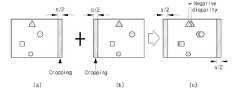
도 9는 도 8의 변위 조정량에 따라 입체 영상을 재생성하는 방법을 설명하기 위한 도면이다.FIG. 9 is a diagram for describing a method of reproducing a stereoscopic image according to the displacement adjustment amount of FIG. 8.
도 9를 참조하면, (a)의 우 영상, (b)의 좌 영상이 합쳐져 (c)의 입체 영상이 생성된다. 이때, 선택된 조정량에 따라 (a)의 우 영상의 우측 끝단에서 선택된 변위 조정량의 반에 해당하는 길이만큼 클로핑한다. 또한, (b)의 좌 영상의 좌측 끝단에서 선택된 변위 조정량의 반에 해당하는 길이만큼 클로핑한다. 그리고, 클로핑한 (a)의 우 영상, (b)의 좌 영상을 합쳐 (c)의 입체 영상을 재생성한다.Referring to FIG. 9, the right image of (a) and the left image of (b) are combined to generate a stereoscopic image of (c). At this time, according to the selected amount of adjustment is clipped by a length corresponding to half of the selected amount of displacement adjustment at the right end of the right image of (a). In addition, the length of the left side of the left image of (b) is clipped by a length corresponding to half of the selected displacement adjustment amount. Then, the stereoscopic image of (c) is regenerated by combining the right image of (a) and the left image of (b).
이로써, 입체 영상 전체에서의 변위량이 줄어들게 된다. 그리고, 시청자의 양안에 편안하고, 최적화된 입체감을 제공하게 된다.As a result, the displacement amount in the whole stereoscopic image is reduced. In addition, it provides a comfortable and optimized three-dimensional effect in both eyes of the viewer.
도 10은 본 발명의 일 실시예에 따른 입체 영상장치의 입체 영상의 변위 조정방법의 설명에 제공되는 흐름도이다.10 is a flowchart provided to explain a method for adjusting displacement of a stereoscopic image of the stereoscopic image apparatus according to the exemplary embodiment of the present invention.
도 10을 참조하면, 변위 추정부(330)는 입력 영상의 변위를 추정하여 변위 히스토그램을 산출한다(S1100). 변위 추정 및 변위 히스토그램 산출방법에 대해서는 도 3 및 도 4에서 설명하였으므로, 구체적인 설명은 생략하기로 한다.Referring to FIG. 10, the
그리고, 변위 조정부(340)는 변위 히스토그램을 이용하여 변위를 조정한다(S1200). 변위 조정방법에 대해서는 도 5 내지 도 8에서 설명하였으므로, 구체적인 설명은 생략하기로 한다.The
입체 영상 재생성부(350)는 조정된 변위에 따라 입체 영상을 재생성한다(S1300). 입체 영상을 재생성하는 방법에 대해서는 도 9를 예를 들어 설명하였으므로, 구체적인 설명은 생략하기로 한다.The
그리고, 지터 제거부(360)는 재생성된 입체 영상의 지터를 제거한다(S1400). 구체적으로, 지터 제거부(360)는 순차적으로 입력되는 입체 영상의 변위 조정량에 대해 윈도우를 적용하여 필터링한다. 그리고, 지터 제거부(360)는 필터링된 변위 조정량을 재생성된 입체 영상에 적용함으로써, 지터를 방지한다.The
재생성된 입체 영상이 디스플레이부(370)에 디스플레이된다(S1500).The reproduced stereoscopic image is displayed on the display unit 370 (S1500).
이상에서는, '3D 안전 가이드 라인'에 기초한 두 개의 변위 범위을 고려하는 것으로 설명하였으나, 이는 일 실시예에 불과한 것으로, 단일 구간으로 한정할 수도 있다. 즉, d[x]가 음의 방향으로 s1만큼 이동되었을 경우에, 변위 에너지가 최대가 되는 이동량을 변위 조정량으로 정할 수 있다.In the above, it has been described as considering two displacement ranges based on the '3D safety guideline', but this is only an example and may be limited to a single section. That is, when d [x] is moved by s1 in the negative direction, the amount of displacement at which the displacement energy is maximum can be determined as the displacement adjustment amount.
그리고, '3D 안전 가이드 라인'에 기초한 두 개의 변위 범위 즉, 쾌적한 양안시차의 범위 ±1도 및 무리없는 양안시차의 범위 ±2도에서의 변위 에너지를 분석하여 변위 조정량을 결정하였으나, 이 또한 일 실시예에 불과하다. 양안시차의 범위 ±1도 이내 및 양안시차의 범위 ±2도 이내의 어느 범위의 변위 에너지를 분석하는 것으로도 설명 가능하며, 융합한계 ±7도 이내에 포함된 어느 범위에서의 변위 에너지를 분석하는 것으로도 구현가능하다. 즉, 사용자마다 최적화된 입체감을 느낄 수 있는 양안시차는 다르기 때문에, 융합한계 ±7도 이내에서 일반적으로 최적화된 입체감을 느낄 수 있는 양안시차 범위를 구하는 실험을 통해 얻은 양안시차 범위의 변위 에너지를 분석하는 것이 가능하다.In addition, the displacement adjustment amount was determined by analyzing the displacement energy in two displacement ranges based on the '3D safety guideline', that is, the range of comfortable binocular disparity ± 1 degree and the range of binocular disparity ± 2 degrees. Only one embodiment. It can also be explained by analyzing displacement energy within a range of ± 1 degree within binocular disparity and within ± 2 degrees of binocular disparity, and by analyzing displacement energy within any range within ± 7 degrees of fusion limit. It is also possible to implement. In other words, the binocular disparity that can feel the optimized three-dimensional effect is different for each user, so the displacement energy of the binocular disparity range obtained through the experiment to obtain a binocular disparity range that can generally feel the optimized three-dimensional sense within the fusion limit ± 7 degrees It is possible to.
이상 설명한 바와 같이, 본 발명에 따르면, 변위 히스토그램의 변위 에너지를 분석하여 변위 조정량을 산출함으로써, 과도한 변위에 의해 발생하는 피로도를 감소시켜 시청자의 양안에 편안하고, 최적화된 입체감을 제공할 수 있다.As described above, according to the present invention, by calculating the displacement adjustment amount by analyzing the displacement energy of the displacement histogram, it is possible to reduce the fatigue caused by excessive displacement, thereby providing a comfortable and optimized three-dimensional feeling in both eyes of the viewer. .
그리고, 본 발명에 따르면, 평행형 또는 다시점 카메라로 촬상한 입체 영상을 이종형 입체 카메라로 촬상한 입체 영상처럼 구현 가능하다.According to the present invention, a stereoscopic image captured by a parallel or multi-view camera may be implemented as a stereoscopic image captured by a heterogeneous stereoscopic camera.
또한, 이상에서는 본 발명의 바람직한 실시예에 대하여 도시하고 설명하였지만, 본 발명은 상술한 특정의 실시예에 한정되지 아니하며, 청구범위에서 청구하는 본 발명의 요지를 벗어남이 없이 당해 발명이 속하는 기술분야에서 통상의 지식을 가진자에 의해 다양한 변형실시가 가능한 것은 물론이고, 이러한 변형실시들은 본 발명의 기술적 사상이나 전망으로부터 이해되어져서는 안 될 것이다.While the present invention has been particularly shown and described with reference to exemplary embodiments thereof, it is to be understood that the invention is not limited to the disclosed exemplary embodiments, but, on the contrary, It will be understood by those skilled in the art that various changes in form and details may be made therein without departing from the spirit and scope of the invention.
Claims (24)
Translated fromKoreanPriority Applications (3)
| Application Number | Priority Date | Filing Date | Title |
|---|---|---|---|
| KR1020060112298AKR101311896B1 (en) | 2006-11-14 | 2006-11-14 | Displacement adjustment method of stereoscopic image and stereoscopic image device applying the same |
| US11/853,166US8019146B2 (en) | 2006-11-14 | 2007-09-11 | Method for adjusting disparity in three-dimensional image and three-dimensional imaging device thereof |
| CN200710180225XACN101184252B (en) | 2006-11-14 | 2007-10-11 | Method for adjusting disparity in three-dimensional image and three-dimensional imaging device thereof |
Applications Claiming Priority (1)
| Application Number | Priority Date | Filing Date | Title |
|---|---|---|---|
| KR1020060112298AKR101311896B1 (en) | 2006-11-14 | 2006-11-14 | Displacement adjustment method of stereoscopic image and stereoscopic image device applying the same |
Publications (2)
| Publication Number | Publication Date |
|---|---|
| KR20080043576A KR20080043576A (en) | 2008-05-19 |
| KR101311896B1true KR101311896B1 (en) | 2013-10-14 |
Family
ID=39369269
Family Applications (1)
| Application Number | Title | Priority Date | Filing Date |
|---|---|---|---|
| KR1020060112298AExpired - Fee RelatedKR101311896B1 (en) | 2006-11-14 | 2006-11-14 | Displacement adjustment method of stereoscopic image and stereoscopic image device applying the same |
Country Status (3)
| Country | Link |
|---|---|
| US (1) | US8019146B2 (en) |
| KR (1) | KR101311896B1 (en) |
| CN (1) | CN101184252B (en) |
Families Citing this family (97)
| Publication number | Priority date | Publication date | Assignee | Title |
|---|---|---|---|---|
| KR101345303B1 (en)* | 2007-03-29 | 2013-12-27 | 삼성전자주식회사 | Dynamic depth control method or apparatus in stereo-view or multiview sequence images |
| KR101310213B1 (en)* | 2009-01-28 | 2013-09-24 | 한국전자통신연구원 | Method and apparatus for improving quality of depth image |
| JP4737573B2 (en)* | 2009-02-05 | 2011-08-03 | 富士フイルム株式会社 | 3D image output apparatus and method |
| JP4995854B2 (en)* | 2009-03-11 | 2012-08-08 | 富士フイルム株式会社 | Imaging apparatus, image correction method, and image correction program |
| JP4915456B2 (en) | 2009-04-03 | 2012-04-11 | ソニー株式会社 | Information processing apparatus, information processing method, and program |
| JP5409107B2 (en)* | 2009-05-13 | 2014-02-05 | 任天堂株式会社 | Display control program, information processing apparatus, display control method, and information processing system |
| KR20110005205A (en)* | 2009-07-09 | 2011-01-17 | 삼성전자주식회사 | Signal processing method and apparatus using screen size of display device |
| US8509519B2 (en)* | 2009-07-29 | 2013-08-13 | Intellectual Ventures Fund 83 Llc | Adjusting perspective and disparity in stereoscopic image pairs |
| US8213052B2 (en)* | 2009-07-31 | 2012-07-03 | Eastman Kodak Company | Digital image brightness adjustment using range information |
| US9380292B2 (en)* | 2009-07-31 | 2016-06-28 | 3Dmedia Corporation | Methods, systems, and computer-readable storage media for generating three-dimensional (3D) images of a scene |
| US8218823B2 (en)* | 2009-08-11 | 2012-07-10 | Eastman Kodak Company | Determining main objects using range information |
| KR20110018261A (en)* | 2009-08-17 | 2011-02-23 | 삼성전자주식회사 | Text subtitle data processing method and playback device |
| US20110052059A1 (en)* | 2009-08-27 | 2011-03-03 | Canon Kabushiki Kaisha | Generating image histogram by parallel processing |
| JP5444955B2 (en)* | 2009-08-31 | 2014-03-19 | ソニー株式会社 | Stereoscopic image display system, parallax conversion device, parallax conversion method, and program |
| JP2011066507A (en)* | 2009-09-15 | 2011-03-31 | Toshiba Corp | Image processing apparatus |
| US8284235B2 (en)* | 2009-09-28 | 2012-10-09 | Sharp Laboratories Of America, Inc. | Reduction of viewer discomfort for stereoscopic images |
| KR101699920B1 (en) | 2009-10-07 | 2017-01-25 | 삼성전자주식회사 | Apparatus and method for controling depth |
| US9699434B2 (en) | 2009-10-07 | 2017-07-04 | Samsung Electronics Co., Ltd. | Apparatus and method for adjusting depth |
| JP4754031B2 (en) | 2009-11-04 | 2011-08-24 | 任天堂株式会社 | Display control program, information processing system, and program used for stereoscopic display control |
| KR101626057B1 (en) | 2009-11-19 | 2016-05-31 | 삼성전자주식회사 | Method and device for disparity estimation from three views |
| US20110169818A1 (en)* | 2010-01-13 | 2011-07-14 | Sharp Laboratories Of America, Inc. | Reducing viewing discomfort |
| JP2011166285A (en)* | 2010-02-05 | 2011-08-25 | Sony Corp | Image display device, image display viewing system and image display method |
| JP2011164202A (en)* | 2010-02-05 | 2011-08-25 | Sony Corp | Image display device, image display system, and image display method |
| US9128367B2 (en)* | 2010-03-05 | 2015-09-08 | Panasonic Intellectual Property Management Co., Ltd. | 3D imaging device and 3D imaging method |
| JP5444452B2 (en) | 2010-03-05 | 2014-03-19 | パナソニック株式会社 | Stereo imaging device and stereo imaging method |
| JP5432365B2 (en) | 2010-03-05 | 2014-03-05 | パナソニック株式会社 | Stereo imaging device and stereo imaging method |
| US20110228051A1 (en)* | 2010-03-17 | 2011-09-22 | Goksel Dedeoglu | Stereoscopic Viewing Comfort Through Gaze Estimation |
| JPWO2011114739A1 (en)* | 2010-03-17 | 2013-06-27 | パナソニック株式会社 | Playback device |
| US8213708B2 (en)* | 2010-03-22 | 2012-07-03 | Eastman Kodak Company | Adjusting perspective for objects in stereoscopic images |
| JP2011203811A (en)* | 2010-03-24 | 2011-10-13 | Fujifilm Corp | Image processing apparatus, image processing method, image processing program, and compound eye digital camera |
| JP5467993B2 (en)* | 2010-03-30 | 2014-04-09 | 富士フイルム株式会社 | Image processing apparatus, compound-eye digital camera, and program |
| JP6073214B2 (en) | 2010-03-31 | 2017-02-01 | トムソン ライセンシングThomson Licensing | Method, apparatus and processor readable medium for processing parallax |
| US20110242342A1 (en) | 2010-04-05 | 2011-10-06 | Qualcomm Incorporated | Combining data from multiple image sensors |
| US8896668B2 (en) | 2010-04-05 | 2014-11-25 | Qualcomm Incorporated | Combining data from multiple image sensors |
| JP2011228862A (en)* | 2010-04-16 | 2011-11-10 | Sony Corp | Data structure, image processing apparatus, image processing method and program |
| JP2011228950A (en)* | 2010-04-20 | 2011-11-10 | Sony Corp | Data structure, image processing apparatus, image processing, method and program |
| GB2479931A (en)* | 2010-04-30 | 2011-11-02 | Sony Corp | A Camera Device, Arrangement and System |
| KR101682205B1 (en)* | 2010-05-03 | 2016-12-05 | 삼성전자주식회사 | Apparatus and method of reducing visual fatigue of 3-dimension image |
| US8970672B2 (en) | 2010-05-28 | 2015-03-03 | Qualcomm Incorporated | Three-dimensional image processing |
| JP5556394B2 (en)* | 2010-06-07 | 2014-07-23 | ソニー株式会社 | Stereoscopic image display system, parallax conversion device, parallax conversion method, and program |
| JP5494283B2 (en)* | 2010-06-24 | 2014-05-14 | ソニー株式会社 | 3D display device and 3D display device control method |
| CN102300105B (en)* | 2010-06-25 | 2013-12-25 | 深圳Tcl新技术有限公司 | Method for converting 2D content into 3D content |
| EP2586209A1 (en) | 2010-06-28 | 2013-05-01 | Thomson Licensing | Method and apparatus for customizing 3-dimensional effects of stereo content |
| US20110316972A1 (en)* | 2010-06-29 | 2011-12-29 | Broadcom Corporation | Displaying graphics with three dimensional video |
| KR101674956B1 (en) | 2010-07-12 | 2016-11-10 | 엘지전자 주식회사 | MOBILE TERMINAL AND METHOD FOR CONTROLLING A THREE DIMENSION IMAGE in thereof |
| KR101809479B1 (en)* | 2010-07-21 | 2017-12-15 | 삼성전자주식회사 | Apparatus for Reproducing 3D Contents and Method thereof |
| JP5336662B2 (en)* | 2010-07-26 | 2013-11-06 | 富士フイルム株式会社 | Image processing apparatus, method, and program |
| WO2012023330A1 (en)* | 2010-08-16 | 2012-02-23 | 富士フイルム株式会社 | Image processing device, image processing method, image processing program, and recording medium |
| EP2429199B1 (en)* | 2010-09-13 | 2018-02-21 | LG Electronics Inc. | Image display apparatus and method for operating the same |
| KR101702967B1 (en)* | 2010-09-13 | 2017-02-06 | 엘지전자 주식회사 | Apparatus for displaying image and method for operating the same |
| US8768044B2 (en)* | 2010-09-14 | 2014-07-01 | Texas Instruments Incorporated | Automatic convergence of stereoscopic images based on disparity maps |
| WO2012037075A1 (en)* | 2010-09-14 | 2012-03-22 | Thomson Licensing | Method of presenting three-dimensional content with disparity adjustments |
| JP5594067B2 (en)* | 2010-11-02 | 2014-09-24 | ソニー株式会社 | Image processing apparatus and image processing method |
| KR20120051308A (en)* | 2010-11-12 | 2012-05-22 | 삼성전자주식회사 | Method for improving 3 dimensional effect and reducing visual fatigue and apparatus of enabling the method |
| JP2014501086A (en)* | 2010-11-23 | 2014-01-16 | 深▲セン▼超多▲維▼光▲電▼子有限公司 | Stereo image acquisition system and method |
| CN102006493A (en)* | 2010-11-26 | 2011-04-06 | 北京新岸线网络技术有限公司 | Parallax adjustment method and device for 3D video image |
| CN102006494A (en)* | 2010-11-26 | 2011-04-06 | 北京新岸线网络技术有限公司 | Method and device for adjusting three-dimensional (3D) video signal |
| US9049423B2 (en)* | 2010-12-01 | 2015-06-02 | Qualcomm Incorporated | Zero disparity plane for feedback-based three-dimensional video |
| CN103404155A (en)* | 2010-12-08 | 2013-11-20 | 汤姆逊许可公司 | Method and system for 3d display with adaptive disparity |
| JP5682291B2 (en)* | 2010-12-20 | 2015-03-11 | ソニー株式会社 | Correction value calculation device, compound eye imaging device, and correction value calculation device control method |
| JP5050094B2 (en)* | 2010-12-21 | 2012-10-17 | 株式会社東芝 | Video processing apparatus and video processing method |
| AU2011356545B2 (en) | 2011-01-18 | 2013-12-19 | Hisense Electric Co., Ltd | Control method and apparatus for stereoscopic display |
| EP2574065B1 (en)* | 2011-01-26 | 2016-09-07 | FUJIFILM Corporation | Image processing device, image-capturing device, reproduction device, and image processing method |
| WO2012100434A1 (en)* | 2011-01-30 | 2012-08-02 | Nokia Corporation | Method, apparatus and computer program product for three-dimensional stereo display |
| KR101796663B1 (en) | 2011-02-07 | 2017-11-10 | 삼성전자 주식회사 | Image processing apparatus and control method thereof |
| JP2012204852A (en)* | 2011-03-23 | 2012-10-22 | Sony Corp | Image processing apparatus and method, and program |
| JP2012205148A (en)* | 2011-03-25 | 2012-10-22 | Kyocera Corp | Electronic apparatus |
| WO2012161734A1 (en) | 2011-05-26 | 2012-11-29 | Thomson Licensing | Scale-independent maps |
| CN103597822A (en)* | 2011-06-06 | 2014-02-19 | 富士胶片株式会社 | Image processing device, compound-eye imaging device, image processing method, and program |
| JP2013005238A (en)* | 2011-06-16 | 2013-01-07 | Sony Corp | Three-dimensional image processing apparatus, three-dimensional image processing method, display apparatus, and computer program |
| US10805625B2 (en)* | 2011-07-05 | 2020-10-13 | Texas Instruments Incorporated | Method, system and computer program product for adjusting a stereoscopic image in response to decoded disparities between views of the stereoscopic image |
| US20130009949A1 (en)* | 2011-07-05 | 2013-01-10 | Texas Instruments Incorporated | Method, system and computer program product for re-convergence of a stereoscopic image |
| JP2013038602A (en)* | 2011-08-08 | 2013-02-21 | Sony Corp | Image processor, image processing method, and program |
| US20130050420A1 (en)* | 2011-08-22 | 2013-02-28 | Ding-Yun Chen | Method and apparatus for performing image processing according to disparity information |
| CN103037236A (en)* | 2011-08-22 | 2013-04-10 | 联发科技股份有限公司 | Image processing method and device |
| KR101843450B1 (en)* | 2011-08-23 | 2018-03-29 | 엘지전자 주식회사 | Mobile terminal and method for controlling of the same |
| US8724896B2 (en) | 2011-08-30 | 2014-05-13 | Dolby Laboratories Licensing Corporation | Method and system for color-grading multi-view content |
| KR20130024504A (en)* | 2011-08-31 | 2013-03-08 | 삼성전기주식회사 | Stereo camera system and method for controlling convergence |
| US9560334B2 (en)* | 2011-09-08 | 2017-01-31 | Qualcomm Incorporated | Methods and apparatus for improved cropping of a stereoscopic image pair |
| CN102427540B (en)* | 2011-09-28 | 2014-04-09 | 深圳超多维光电子有限公司 | Three-dimensional image filtering method and corresponding image processing device as well as terminal equipment |
| CN103108199A (en)* | 2011-11-09 | 2013-05-15 | 宏碁股份有限公司 | Dynamic depth of field adjusting device and method thereof |
| TW201325204A (en)* | 2011-12-15 | 2013-06-16 | Ind Tech Res Inst | Stereoscopic image pickup and display quality estimation system and method applicable thereto |
| KR101872864B1 (en)* | 2011-12-19 | 2018-06-29 | 엘지전자 주식회사 | Electronic device and controlling method for electronic device |
| WO2013102790A2 (en)* | 2012-01-04 | 2013-07-11 | Thomson Licensing | Processing 3d image sequences cross reference to related applications |
| US8619148B1 (en)* | 2012-01-04 | 2013-12-31 | Audience, Inc. | Image correction after combining images from multiple cameras |
| TWI514849B (en)* | 2012-01-11 | 2015-12-21 | Himax Tech Ltd | Calibration device used in stereoscopic display system and calibration method of the same |
| US9070196B2 (en)* | 2012-02-27 | 2015-06-30 | Samsung Electronics Co., Ltd. | Apparatus and method for estimating disparity using visibility energy model |
| CN104185985A (en)* | 2012-03-30 | 2014-12-03 | 富士胶片株式会社 | Image pick-up device, method, storage medium, and program |
| US10178368B2 (en)* | 2012-10-23 | 2019-01-08 | Intuitive Surgical Operations, Inc. | Stereo imaging system with automatic disparity adjustment for displaying close range objects |
| TWI502544B (en)* | 2013-03-07 | 2015-10-01 | Acer Inc | Disparity estimation method of stereoscopic image |
| US9934451B2 (en) | 2013-06-25 | 2018-04-03 | Microsoft Technology Licensing, Llc | Stereoscopic object detection leveraging assumed distance |
| US9736467B2 (en)* | 2013-08-05 | 2017-08-15 | Samsung Display Co., Ltd. | Apparatus and method for adjusting stereoscopic images in response to head roll |
| KR102130123B1 (en)* | 2013-10-31 | 2020-07-03 | 삼성전자주식회사 | Multi view image display apparatus and control method thereof |
| JP6365153B2 (en)* | 2014-09-10 | 2018-08-01 | 株式会社ソシオネクスト | Image encoding method and image encoding apparatus |
| US9253442B1 (en)* | 2014-10-07 | 2016-02-02 | Sap Se | Holopresence system |
| CN108885335B (en)* | 2016-03-30 | 2021-10-22 | 索尼奥林巴斯医疗解决方案公司 | Medical stereoscopic viewing device, medical stereoscopic viewing method, and program |
| CN108924527A (en)* | 2017-03-31 | 2018-11-30 | 深圳市易快来科技股份有限公司 | A kind of twin-lens 3D shooting is to realize method, apparatus and the mobile terminal of the depth of field |
Citations (2)
| Publication number | Priority date | Publication date | Assignee | Title |
|---|---|---|---|---|
| KR20050046108A (en)* | 2003-11-13 | 2005-05-18 | 삼성전자주식회사 | Apparatus and method of temporal smoothing for intermediate image generation |
| KR20060063575A (en)* | 2004-12-06 | 2006-06-12 | 한국전자통신연구원 | Image distortion correction device and method of stereo camera |
Family Cites Families (12)
| Publication number | Priority date | Publication date | Assignee | Title |
|---|---|---|---|---|
| JP3539788B2 (en)* | 1995-04-21 | 2004-07-07 | パナソニック モバイルコミュニケーションズ株式会社 | Image matching method |
| DE19636028C1 (en)* | 1996-09-05 | 1997-11-20 | Daimler Benz Ag | Stereo image object detection, esp. for road vehicles |
| JP3255360B2 (en)* | 1999-09-22 | 2002-02-12 | 富士重工業株式会社 | Inspection method of distance data and its inspection device |
| US6606406B1 (en)* | 2000-05-04 | 2003-08-12 | Microsoft Corporation | System and method for progressive stereo matching of digital images |
| US8369607B2 (en)* | 2002-03-27 | 2013-02-05 | Sanyo Electric Co., Ltd. | Method and apparatus for processing three-dimensional images |
| EP2357841B1 (en)* | 2002-03-27 | 2015-07-22 | Sanyo Electric Co., Ltd. | Method and apparatus for processing three-dimensional images |
| US7623674B2 (en)* | 2003-11-05 | 2009-11-24 | Cognex Technology And Investment Corporation | Method and system for enhanced portal security through stereoscopy |
| EP1591963B1 (en)* | 2004-04-29 | 2008-07-09 | Mitsubishi Electric Information Technology Centre Europe B.V. | Adaptive quantisation of a depth map |
| JP2008537190A (en)* | 2005-01-07 | 2008-09-11 | ジェスチャー テック,インコーポレイテッド | Generation of three-dimensional image of object by irradiating with infrared pattern |
| JP4177826B2 (en)* | 2005-03-23 | 2008-11-05 | 株式会社東芝 | Image processing apparatus and image processing method |
| KR101185870B1 (en)* | 2005-10-12 | 2012-09-25 | 삼성전자주식회사 | Apparatus and method for processing 3 dimensional picture |
| WO2009020277A1 (en)* | 2007-08-06 | 2009-02-12 | Samsung Electronics Co., Ltd. | Method and apparatus for reproducing stereoscopic image using depth control |
- 2006
- 2006-11-14KRKR1020060112298Apatent/KR101311896B1/ennot_activeExpired - Fee Related
- 2007
- 2007-09-11USUS11/853,166patent/US8019146B2/ennot_activeExpired - Fee Related
- 2007-10-11CNCN200710180225XApatent/CN101184252B/ennot_activeExpired - Fee Related
Patent Citations (2)
| Publication number | Priority date | Publication date | Assignee | Title |
|---|---|---|---|---|
| KR20050046108A (en)* | 2003-11-13 | 2005-05-18 | 삼성전자주식회사 | Apparatus and method of temporal smoothing for intermediate image generation |
| KR20060063575A (en)* | 2004-12-06 | 2006-06-12 | 한국전자통신연구원 | Image distortion correction device and method of stereo camera |
Also Published As
| Publication number | Publication date |
|---|---|
| US20080112616A1 (en) | 2008-05-15 |
| US8019146B2 (en) | 2011-09-13 |
| CN101184252B (en) | 2012-08-29 |
| KR20080043576A (en) | 2008-05-19 |
| CN101184252A (en) | 2008-05-21 |
Similar Documents
| Publication | Publication Date | Title |
|---|---|---|
| KR101311896B1 (en) | Displacement adjustment method of stereoscopic image and stereoscopic image device applying the same | |
| KR100739730B1 (en) | 3D stereoscopic image processing apparatus and method | |
| JP5347717B2 (en) | Image processing apparatus, image processing method, and program | |
| US7983477B2 (en) | Method and apparatus for generating a stereoscopic image | |
| US8866884B2 (en) | Image processing apparatus, image processing method and program | |
| US8953023B2 (en) | Stereoscopic depth mapping | |
| KR101185870B1 (en) | Apparatus and method for processing 3 dimensional picture | |
| US6031564A (en) | Method and apparatus for monoscopic to stereoscopic image conversion | |
| EP2472883A1 (en) | Three-dimensional image display system, parallax conversion device, parallax conversion method, and program | |
| JP5963422B2 (en) | Imaging apparatus, display apparatus, computer program, and stereoscopic image display system | |
| US20110109731A1 (en) | Method and apparatus for adjusting parallax in three-dimensional video | |
| JP5299111B2 (en) | Image processing apparatus, image processing method, and program | |
| CN101276060A (en) | Method and device for controlling dynamic depth of stereoscopic view or multi-view sequence images | |
| KR20110083650A (en) | How to process parallax information contained in a signal | |
| Jung et al. | Visual comfort improvement in stereoscopic 3D displays using perceptually plausible assessment metric of visual comfort | |
| KR20120030005A (en) | Image processing device and method, and stereoscopic image display device | |
| KR100439341B1 (en) | Depth of field adjustment apparatus and method of stereo image for reduction of visual fatigue | |
| KR100392381B1 (en) | Method and apparatus controlling the disparity of objects in images and a parallel-axis stereo camera system using the apparatus | |
| US20130016187A1 (en) | Method and apparatus for auto-convergence for stereoscopic images and videos | |
| JP6017144B2 (en) | Image processing apparatus and method, program, and recording medium | |
| KR100597587B1 (en) | Vergence Control Device Using Corrected Image Signal Processing and Its Method and Parallel-Axis Stereoscopic Camera System Using the Same | |
| KR20040018858A (en) | Depth of field adjustment apparatus and method of stereo image for reduction of visual fatigue | |
| WO2012039340A1 (en) | Image processing device, image processing method, and program | |
| JP5569635B2 (en) | Image processing apparatus, image processing method, and program | |
| Zhang et al. | Auto convergence for stereoscopic 3D cameras |
Legal Events
| Date | Code | Title | Description |
|---|---|---|---|
| PA0109 | Patent application | St.27 status event code:A-0-1-A10-A12-nap-PA0109 | |
| PG1501 | Laying open of application | St.27 status event code:A-1-1-Q10-Q12-nap-PG1501 | |
| A201 | Request for examination | ||
| PA0201 | Request for examination | St.27 status event code:A-1-2-D10-D11-exm-PA0201 | |
| P11-X000 | Amendment of application requested | St.27 status event code:A-2-2-P10-P11-nap-X000 | |
| P13-X000 | Application amended | St.27 status event code:A-2-2-P10-P13-nap-X000 | |
| D13-X000 | Search requested | St.27 status event code:A-1-2-D10-D13-srh-X000 | |
| R18-X000 | Changes to party contact information recorded | St.27 status event code:A-3-3-R10-R18-oth-X000 | |
| D14-X000 | Search report completed | St.27 status event code:A-1-2-D10-D14-srh-X000 | |
| E902 | Notification of reason for refusal | ||
| PE0902 | Notice of grounds for rejection | St.27 status event code:A-1-2-D10-D21-exm-PE0902 | |
| T11-X000 | Administrative time limit extension requested | St.27 status event code:U-3-3-T10-T11-oth-X000 | |
| E701 | Decision to grant or registration of patent right | ||
| PE0701 | Decision of registration | St.27 status event code:A-1-2-D10-D22-exm-PE0701 | |
| GRNT | Written decision to grant | ||
| PR0701 | Registration of establishment | St.27 status event code:A-2-4-F10-F11-exm-PR0701 | |
| PR1002 | Payment of registration fee | St.27 status event code:A-2-2-U10-U11-oth-PR1002 Fee payment year number:1 | |
| PG1601 | Publication of registration | St.27 status event code:A-4-4-Q10-Q13-nap-PG1601 | |
| FPAY | Annual fee payment | Payment date:20160830 Year of fee payment:4 | |
| PR1001 | Payment of annual fee | St.27 status event code:A-4-4-U10-U11-oth-PR1001 Fee payment year number:4 | |
| FPAY | Annual fee payment | Payment date:20170830 Year of fee payment:5 | |
| PR1001 | Payment of annual fee | St.27 status event code:A-4-4-U10-U11-oth-PR1001 Fee payment year number:5 | |
| P22-X000 | Classification modified | St.27 status event code:A-4-4-P10-P22-nap-X000 | |
| FPAY | Annual fee payment | Payment date:20180830 Year of fee payment:6 | |
| PR1001 | Payment of annual fee | St.27 status event code:A-4-4-U10-U11-oth-PR1001 Fee payment year number:6 | |
| PC1903 | Unpaid annual fee | St.27 status event code:A-4-4-U10-U13-oth-PC1903 Not in force date:20190918 Payment event data comment text:Termination Category : DEFAULT_OF_REGISTRATION_FEE | |
| PC1903 | Unpaid annual fee | St.27 status event code:N-4-6-H10-H13-oth-PC1903 Ip right cessation event data comment text:Termination Category : DEFAULT_OF_REGISTRATION_FEE Not in force date:20190918 |