KR101305823B1 - Apparatus for relaying wireless power, method for transmitting wireless power and method for contorlling resonance frequency - Google Patents
Apparatus for relaying wireless power, method for transmitting wireless power and method for contorlling resonance frequencyDownload PDFInfo
- Publication number
- KR101305823B1 KR101305823B1KR1020110124419AKR20110124419AKR101305823B1KR 101305823 B1KR101305823 B1KR 101305823B1KR 1020110124419 AKR1020110124419 AKR 1020110124419AKR 20110124419 AKR20110124419 AKR 20110124419AKR 101305823 B1KR101305823 B1KR 101305823B1
- Authority
- KR
- South Korea
- Prior art keywords
- wireless power
- resonant
- coil
- resonance
- power receiver
- Prior art date
- Legal status (The legal status is an assumption and is not a legal conclusion. Google has not performed a legal analysis and makes no representation as to the accuracy of the status listed.)
- Expired - Fee Related
Links
Images


Classifications
- H—ELECTRICITY
- H02—GENERATION; CONVERSION OR DISTRIBUTION OF ELECTRIC POWER
- H02J—CIRCUIT ARRANGEMENTS OR SYSTEMS FOR SUPPLYING OR DISTRIBUTING ELECTRIC POWER; SYSTEMS FOR STORING ELECTRIC ENERGY
- H02J50/00—Circuit arrangements or systems for wireless supply or distribution of electric power
- H02J50/50—Circuit arrangements or systems for wireless supply or distribution of electric power using additional energy repeaters between transmitting devices and receiving devices
- H—ELECTRICITY
- H02—GENERATION; CONVERSION OR DISTRIBUTION OF ELECTRIC POWER
- H02J—CIRCUIT ARRANGEMENTS OR SYSTEMS FOR SUPPLYING OR DISTRIBUTING ELECTRIC POWER; SYSTEMS FOR STORING ELECTRIC ENERGY
- H02J50/00—Circuit arrangements or systems for wireless supply or distribution of electric power
- H02J50/80—Circuit arrangements or systems for wireless supply or distribution of electric power involving the exchange of data, concerning supply or distribution of electric power, between transmitting devices and receiving devices
- H—ELECTRICITY
- H02—GENERATION; CONVERSION OR DISTRIBUTION OF ELECTRIC POWER
- H02J—CIRCUIT ARRANGEMENTS OR SYSTEMS FOR SUPPLYING OR DISTRIBUTING ELECTRIC POWER; SYSTEMS FOR STORING ELECTRIC ENERGY
- H02J50/00—Circuit arrangements or systems for wireless supply or distribution of electric power
- H02J50/10—Circuit arrangements or systems for wireless supply or distribution of electric power using inductive coupling
- H02J50/12—Circuit arrangements or systems for wireless supply or distribution of electric power using inductive coupling of the resonant type
- H—ELECTRICITY
- H02—GENERATION; CONVERSION OR DISTRIBUTION OF ELECTRIC POWER
- H02J—CIRCUIT ARRANGEMENTS OR SYSTEMS FOR SUPPLYING OR DISTRIBUTING ELECTRIC POWER; SYSTEMS FOR STORING ELECTRIC ENERGY
- H02J50/00—Circuit arrangements or systems for wireless supply or distribution of electric power
- H02J50/90—Circuit arrangements or systems for wireless supply or distribution of electric power involving detection or optimisation of position, e.g. alignment
- H—ELECTRICITY
- H03—ELECTRONIC CIRCUITRY
- H03H—IMPEDANCE NETWORKS, e.g. RESONANT CIRCUITS; RESONATORS
- H03H3/00—Apparatus or processes specially adapted for the manufacture of impedance networks, resonating circuits, resonators
- H03H3/007—Apparatus or processes specially adapted for the manufacture of impedance networks, resonating circuits, resonators for the manufacture of electromechanical resonators or networks
- H03H3/0072—Apparatus or processes specially adapted for the manufacture of impedance networks, resonating circuits, resonators for the manufacture of electromechanical resonators or networks of microelectro-mechanical resonators or networks
- H03H3/0076—Apparatus or processes specially adapted for the manufacture of impedance networks, resonating circuits, resonators for the manufacture of electromechanical resonators or networks of microelectro-mechanical resonators or networks for obtaining desired frequency or temperature coefficients
- H03H3/0077—Apparatus or processes specially adapted for the manufacture of impedance networks, resonating circuits, resonators for the manufacture of electromechanical resonators or networks of microelectro-mechanical resonators or networks for obtaining desired frequency or temperature coefficients by tuning of resonance frequency
- H—ELECTRICITY
- H04—ELECTRIC COMMUNICATION TECHNIQUE
- H04B—TRANSMISSION
- H04B5/00—Near-field transmission systems, e.g. inductive or capacitive transmission systems
- H04B5/20—Near-field transmission systems, e.g. inductive or capacitive transmission systems characterised by the transmission technique; characterised by the transmission medium
- H04B5/24—Inductive coupling
- H04B5/26—Inductive coupling using coils
- H—ELECTRICITY
- H04—ELECTRIC COMMUNICATION TECHNIQUE
- H04B—TRANSMISSION
- H04B5/00—Near-field transmission systems, e.g. inductive or capacitive transmission systems
- H04B5/70—Near-field transmission systems, e.g. inductive or capacitive transmission systems specially adapted for specific purposes
- H04B5/79—Near-field transmission systems, e.g. inductive or capacitive transmission systems specially adapted for specific purposes for data transfer in combination with power transfer
Landscapes
- Engineering & Computer Science (AREA)
- Computer Networks & Wireless Communication (AREA)
- Power Engineering (AREA)
- Signal Processing (AREA)
- Manufacturing & Machinery (AREA)
- Charge And Discharge Circuits For Batteries Or The Like (AREA)
- Near-Field Transmission Systems (AREA)
Abstract
Translated fromKorean
Description
Translated fromKorean본 발명은 무선전력 중계장치, 무선전력 전송 방법 및 공진주파수 조절 방법 에 관한 것이다.The present invention relates to a wireless power repeater, a wireless power transmission method and a resonance frequency adjustment method.
무선으로 전기 에너지를 원하는 기기로 전달하는 무선전력전송 기술(wireless power transmission 또는 wireless energy transfer)은 이미 1800년대에 전자기유도 원리를 이용한 전기 모터나 변압기에 사용되기 시작했고, 그 후로는 라디오파(Radio Frequency)나 레이저를 방사해서 전기에너지를 전송하는 방법도 시도되었다. 우리가 흔히 사용하는 전동칫솔이나 일부 무선면도기도 실상은 전자기유도 원리로 충전된다. 현재까지 무선 방식에 의한 에너지 전달 방식은 자기 유도, 자기 공진 및 마이크로파를 이용한 원거리 송신 기술 등이 있다.Wireless power transmission (wireless power transmission or wireless energy transfer), which wirelessly transfers electrical energy to a desired device, has already been used in electric motors and transformers using electromagnetic induction principles in the 1800's, and since then The method of transmitting electrical energy by radiating a frequency or laser has also been attempted. Our electric toothbrushes and some wireless shavers are actually charged with electromagnetic induction. To date, wireless energy transfer methods include magnetic induction, magnetic resonance, and long-range transmission technology using microwaves.
최근에는 이와 같은 무선 전력 전송 기술 중 자기 공진을 이용한 에너지 전달 방식이 많이 사용되고 있다.In recent years, among such wireless power transmission techniques, energy transmission using self resonance is widely used.
자기 공진을 이용한 무선전력 전송 시스템은 송신 측과 수신 측에 형성된 전기신호가 코일을 통해 무선으로 전달되기 때문에 사용자는 휴대용 기기와 같은 전자기기를 손쉽게 충전할 수 있다.In the wireless power transmission system using self-resonance, since the electric signals formed on the transmission side and the reception side are wirelessly transmitted through the coil, the user can easily charge electronic devices such as portable devices.
그러나, 현재의 무선충전기술은 단일 소스를 사용하여 단일 휴대용 수신 기기만을 충전하고 있으며, 송신 측과 수신 측 사이의 거리는 매우 제한적인 단점이 있다.However, current wireless charging technology charges only a single portable receiving device using a single source, and the distance between the transmitting side and the receiving side has a very limited disadvantage.
특히, 다중 기기 무선 충전을 위하여 공진 코일의 면적을 크게 하는 방법도 있으나(특허공개번호 10-2010-0026075), 이 경우는 무선전력 수신장치가 존재하지 않는 부분에도 불필요한 자기장이 발생하여 전력전송 효율이 매우 낮고, 유해 전자기장의 크기가 높은 문제가 있다.In particular, there is a method of increasing the area of the resonant coil for wireless charging of multiple devices (Patent Publication No. 10-2010-0026075), but in this case, an unnecessary magnetic field is generated even in a portion where the wireless power receiver does not exist, thereby providing power transmission efficiency. This is a problem of very low and high magnitude of harmful electromagnetic field.
본 발명은 하나 이상의 공진 코일들을 선택적으로 동작시켜 전력전달 효율을 증가시키고, 자기장의 세기를 최소화하는 무선전력 중계장치, 무선전력 전송 방법 및 공진주파수 조절 방법의 제공을 목적으로 한다.An object of the present invention is to provide a wireless power repeater, a wireless power transmission method and a resonant frequency control method for selectively operating one or more resonant coils to increase power transmission efficiency and minimize magnetic field strength.
본 발명의 실시예에 따른 자기 공진을 이용하여 무선전력 수신장치에 전력을 전송하는 무선전력 중계장치는 전력소스로부터 전력을 수신하는 송신 공진 코일;According to an embodiment of the present invention, a wireless power relay apparatus for transmitting power to a wireless power receiver using magnetic resonance includes a transmission resonance coil receiving power from a power source;
상기 송신 공진 코일로부터 전력을 수신하고, 상기 수신한 전력을 상기 무선전력 수신장치에 전달하는 복수의 공진 코일들; 상기 무선전력 수신장치의 근접여부를 검출하는 검출부; 및 상기 검출부의 검출결과에 따라 상기 복수의 공진 코일들 중 상기 무선전력 수신장치가 검출된 영역 내의 공진 코일을 상기 송신 공진 코일에 연결 또는 분리시키는 복수의 스위치들을 포함하는 것을 특징으로 한다.A plurality of resonant coils receiving power from the transmission resonant coil and transferring the received power to the wireless power receiver; A detector for detecting proximity of the wireless power receiver; And a plurality of switches for connecting or disconnecting a resonant coil in an area in which the wireless power receiver is detected among the plurality of resonant coils to the transmission resonant coil according to a detection result of the detector.
본 발명의 또 다른 실시 예에 따른 자기공진을 이용한 무선전력 전송 방법은,Wireless power transmission method using a magnetic resonance according to another embodiment of the present invention,
제1 영역 내에서 제1 공진 코일을 통해 전력을 수신하는 제1 무선전력 수신장치를 검출하는 단계; 상기 제1 무선전력 수신장치가 검출된 경우, 상기 제1 공진 코일과 페어링되는 제1 스위치를 개방시키는 단계; 상기 제1 스위치의 개방에 따라 제1 무선전력 수신장치에 전력을 전송하는 단계; 상기 전력 전송 중 제2 영역 내에서 제2 공진 코일을 통해 전력을 수신하는 제2 무선전력 수신장치를 검출하는 단계; 상기 제2 무선전력 수신장치가 검출된 경우, 상기 제2 공진 코일과 페어링되는 제2 스위치를 개방시키는 단계; 및 상기 제2 스위치의 개방에 따라 제2 무선전력 수신장치에 전력을 전송하는 단계를 포함하는 것을 특징으로 한다.Detecting a first wireless power receiver receiving power through the first resonant coil in the first region; Opening the first switch paired with the first resonant coil when the first wireless power receiver is detected; Transmitting power to a first wireless power receiver according to the opening of the first switch; Detecting a second wireless power receiver receiving power through a second resonant coil in a second area of the power transmission; Opening a second switch paired with the second resonant coil when the second wireless power receiver is detected; And transmitting power to a second wireless power receiver according to the opening of the second switch.
본 발명의 또 다른 실시 예에 따른 자기공진을 이용한 무선전력 중계장치의 공진주파수 조절 방법에 있어서, 상기 무선전력 중계장치는, 송신 공진 코일, 복수의 공진 코일들, 상기 복수의 공진 코일들과 페어링된 복수의 스위치들을 포함하고, 하나 이상의 무선전력 수신장치를 검출하는 단계; 상기 검출된 하나 이상의 무선전력 수신장치에 전력을 전달하는 상기 복수의 공진 코일들을 상기 복수의 스위치들을 통해 상기 송신 공진 코일과 연결시키는 단계; 상기 무선전력 중계장치의 공진주파수가 변경되었는지 판단하는 단계; 상기 판단결과, 상기 공진주파수가 변경된 경우, 원래의 공진주파수로 재 변경시키는 단계를 포함하는 것을 특징으로 한다.In a method of adjusting a resonance frequency of a wireless power repeater using magnetic resonance according to another embodiment of the present invention, the wireless power repeater is paired with a transmission resonant coil, a plurality of resonant coils, and a plurality of resonant coils. Detecting at least one wireless power receiver including a plurality of switches; Coupling the plurality of resonant coils for transmitting power to the detected one or more wireless power receivers with the transmission resonant coils through the plurality of switches; Determining whether a resonant frequency of the wireless power repeater has been changed; As a result of the determination, if the resonant frequency is changed, characterized in that it comprises the step of changing back to the original resonant frequency.
한편, 상기 공진주파수 조절 방법은 컴퓨터에서 실행시키기 위한 프로그램으로 제작되어 컴퓨터가 읽을 수 있는 기록매체로 구현될 수 있다.On the other hand, the resonant frequency adjustment method may be implemented in a computer-readable recording medium produced as a program for execution in a computer.
본 발명의 실시예에 따르면, 다음과 같은 효과가 있다.According to the embodiment of the present invention, the following effects can be obtained.
첫째, 무선전력 수신장치가 배치되는 영역의 공진 코일만을 선택적으로 동작시켜서 전력전달 효율을 증가시키고, 자기장의 세기를 줄일 수 있다.First, it is possible to selectively operate only the resonant coil in the region where the wireless power receiver is disposed to increase the power transmission efficiency and reduce the strength of the magnetic field.
둘째, 가변 인덕터 및 가변 커패시터의 삽입을 통해 공진주파수를 지속적으로 유지할 수 있어 전력전달 효율을 증가시킨다.Second, the resonant frequency can be continuously maintained through the insertion of the variable inductor and the variable capacitor, thereby increasing the power transfer efficiency.
한편 그 외의 다양한 효과는 후술될 본 발명의 실시 예에 따른 상세한 설명에서 직접적 또는 암시적으로 개시될 것이다.Meanwhile, various other effects will be directly or implicitly disclosed in the detailed description according to the embodiment of the present invention to be described later.
도 1은 본 발명의 일 실시예에 따른 무선전력 전송 시스템을 나타낸다.
도 2는 본 발명의 일 실시예에 따른, 송신 유도 코일(210)의 등가 회로도이다.
도 3은 본 발명의 일 실시예에 따른, 전력 소스(100)와 무선전력 송신장치(200)의 등가회로이다.
도 4는 본 발명의 일 실시예에 따른 수신 공진 코일(310), 수신 유도 코일(320), 정류 회로(330) 및 부하(340)의 등가회로를 나타낸다.
도 5는 본 발명의 일 실시 예에 따른 무선전력 중계장치(400)의 구성도이다.
도 6은 본 발명의 일 실시 예에 따른 무선전력 중계장치(400)의 회로도이다.
도 7은 본 발명의 일 실시 예에 따른 무선전력 중계장치(400)를 이용한 무선전력 전송 방법의 흐름도이다.
도 8은 본 발명의 일 실시 예에 따른 공진주파수 조절 방법을 나타낸 흐름도이다.
도 9는 본 발명의 일 실시 예에 따른 루프형 공진 코일들을 포함하는 무선전력 중계장치(400)를 사용한 경우, 자기장의 세기를 검출한 시뮬레이션 결과를 나타낸 도면이다.
도 10은 도 9에 도시한 무선전력 중계장치(400)의 단면에 대한 자기장의 세기를 나타낸 그래프이다.1 shows a wireless power transmission system according to an embodiment of the present invention.
2 is an equivalent circuit diagram of a
3 is an equivalent circuit of the
4 illustrates an equivalent circuit of the
5 is a block diagram of a
6 is a circuit diagram of a
7 is a flowchart illustrating a wireless power transmission method using the
8 is a flowchart illustrating a resonant frequency adjusting method according to an exemplary embodiment of the present invention.
9 is a diagram illustrating a simulation result of detecting the strength of a magnetic field when a
FIG. 10 is a graph showing the strength of the magnetic field with respect to the cross section of the
이하에서는, 첨부된 도면을 참조하여 본 발명의 바람직한 실시예에 대하여 본 발명이 속하는 기술분야에서 통상의 지식을 가진 자가 용이하게 실시할 수 있도록 상세히 설명한다.
Hereinafter, exemplary embodiments of the present invention will be described in detail with reference to the accompanying drawings so that those skilled in the art may easily implement the present invention.
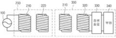
도 1은 본 발명의 일 실시예에 따른 무선 전력 전송 시스템을 나타낸다.1 shows a wireless power transmission system according to an embodiment of the present invention.
전력 소스(100)에서 생성된 전력은 무선전력 송신장치(200)로 전달되고, 자기 공진 현상에 의해 무선전력 송신장치(200)와 공진을 이루는 즉, 공진 주파수 값이 동일한 무선전력 수신장치(300)로 전달된다.The power generated by the
보다 구체적으로 살펴보면, 전력 소스(100)는 소정 주파수의 교류 전력을 제공하는 교류 신호 소스이다.More specifically, the
무선전력 송신장치(200)는 송신 유도 코일(210)과 송신 공진 코일(220)로 구성된다. 송신 유도 코일(210)은 전력 소스(100)와 연결되며, 교류 전류가 흐른다. 송신 유도 코일(210)에 교류 전류가 흐르면, 전자기 유도에 의해 물리적으로 이격되어 있는 송신 공진 코일(220)에도 교류 전류가 유도된다. 송신 공진 코일(220)로 전달된 전력은 자기 공진에 의해 무선전력 송신장치(200)와 공진 회로를 이루는 무선전력 수신장치(300)로 전달된다.The
임피던스가 매칭된 2개의 LC 회로 사이는 자기 공진에 의해 전력이 전송될 수 있다. 이와 같은 자기 공진에 의한 전력 전송은 전자기 유도에 의한 전력 전송보다 더 먼 거리까지 더 높은 효율로 전력 전달이 가능하게 한다.Power can be transmitted by self resonance between two LC circuits whose impedance is matched. Such power transmission by self-resonance enables power transmission to a higher efficiency, farther than the power transmission by electromagnetic induction.
무선전력 수신장치(300)는 수신 공진 코일(310), 수신 유도 코일(320), 정류회로(330) 및 부하(340)로 구성된다. 송신 공진 코일(220)에 의해 송신된 전력은 수신 공진 코일(310)에 의해 수신되어 수신 공진 코일(310)에 교류 전류가 흐르게 된다. 수신 공진 코일(310)로 전달된 전력은 전자기 유도에 의해 수신 유도 코일(320)로 전달된다. 수신 유도 코일(320)로 전달된 전력은 정류 회로(330)를 통해 정류되어 부하(340)로 전달된다.
The
도 2는 본 발명의 일 실시예에 따른, 송신 유도 코일(210)의 등가 회로도이다. 도 2에 도시된 바와 같이 송신 유도 코일(210)은 인덕터(L1)와 캐패시터(C1)로 구성될 수 있으며, 이들에 의해 적절한 인덕턴스와 캐패시턴스 값을 갖는 회로를 구성하게 된다. 캐패시터(C1)는 가변 캐패시터일 수 있으며, 가변 캐패시터를 조절하여 임피던스 매칭을 수행할 수 있다. 송신 공진 코일(220), 수신 공진 코일(310), 수신 유도 코일(320)의 등가 회로도 도 2에 도시된 것과 동일할 수 있다.
2 is an equivalent circuit diagram of a
도 3은 본 발명의 일 실시예에 따른, 전력 소스(100)와 무선전력 송신장치(200)의 등가회로이다. 도 3에 도시된 바와 같이, 송신 유도 코일(210)과 송신 공진 코일(220)은 각각 소정 인덕턴스 값과 캐패시턴스 값을 갖는 인덕터(L1, L2)와 캐패시터(C1, C2)로 구성될 수 있다.
3 is an equivalent circuit of the
도 4는 본 발명의 일 실시예에 따른, 수신 공진 코일(310), 수신 유도 코일(320), 정류회로(330) 및 부하(340)의 등가회로를 나타낸다.4 illustrates an equivalent circuit of the
도 4에 도시된 바와 같이 수신 공진 코일(310)과 수신 유도 코일(320)은 각각 소정 인덕턴스 값과 캐패시턴스 값을 갖는 인덕터(L3, L4)와 캐패시터(C3, C4)로 구성될 수 있다. 정류회로(330)는 다이오드(D1)와 정류 캐패시터(C5)로 구성될 수 있으며, 교류 전력을 직류 전력을 변환하여 출력한다. 부하(340)는 1.3V의 직류 전원으로 표시되어 있으나, 직류 전력을 필요로 하는 임의의 충전지 또는 장치일 수 있다.
As shown in FIG. 4, the
도 5는 본 발명의 일 실시 예에 따른 무선전력 중계장치(400)의 구성도이다.5 is a block diagram of a
도 5를 참조하면, 무선전력 중계장치(400)는 송신 공진 코일(410), 제1,2 공진 코일(421, 422), 제1,2 스위치(431, 432), 검출부(440) 및 제어부(450)를 포함할 수 있다.Referring to FIG. 5, the
도 5에서는 무선전력 중계장치(400)가 2개의 공진 코일을 포함하는 경우를 예로 들었으나, 이는 예시에 불과하고, 무선전력 중계장치(400)는 2개 이상의 복수의 공진 코일들을 포함할 수 있다. 또한, 2개의 스위치를 포함하는 경우를 예로 들었으나, 이는 예시에 불과하고, 2개 이상의 복수의 스위치들을 포함할 수 있다. 각 공진 코일들과 각 스위치는 하나씩 페어링되어 한 쌍을 이룰 수 있다.In FIG. 5, the
송신 공진 코일(410)은 전력소스(100)로부터 교류전력을 수신할 수 있고, 수신한 전력을 제1,2 공진 코일(421,422)에 동시에 또는 어느 하나에만 전달할 수 있다.The transmission
제1,2 공진 코일(421,422)은 송신 공진 코일(410)로부터 전력을 수신하고, 수신한 전력을 자기 공진에 의해 무선전력 수신장치에 전송할 수 있다. 제1,2 공진 코일들(421,422)은 도 2에 도시한 송신 유도 코일(210)의 등가 회로도와 같이 구현될 수 있다. 일 실시 예에서 제1,2 공진 코일(421,422)은 하나의 도선이 적어도 한 번 이상 감겨진 루프형태일 수 있고, 루프형태는 원형, 타원형, 사각형 등과 같은 다각형의 형태일 수 있으나, 이에 한정되지 않는다. 도 5에서는 제1,2 공진 코일(421,422)이 사각형의 루프형태로 구성됨을 보여준다.The first and second
일 실시 예에서 송신 공진 코일(410) 및 제1,2 공진 코일(421,422)은 다중 탭(Multi Tab)구조를 가질 수 있다. 다중 탭 구조란, 예를 들어, 제1 공진 코일(421)이 총 5번으로 감겨진 경우, 공진 코일의 외부 루프와 내부 루프 사이에 일정 공간을 두고, 외부 루프 및 내부 루프의 감겨진 횟수를 달리하는 구조를 의미할 수 있다. 일 실시 예에서 제1 공진 코일(421)의 외부 루프는 3번 감겨지고, 내부 루프는 2번 감겨질 수 있으나, 이는 예시에 불과하다.According to an embodiment, the transmission
송신 공진 코일(410) 및 제1,2 공진 코일(421,422)은 하나의 도선으로 연결될 수 있다. 즉, 송신 공진 코일(410) 및 제1,2 공진 코일(421,422)은 전기적으로 직렬연결 될 수 있다.The transmission
제1 스위치(431)는 후술할 제어부의 구동신호에 따라 송신 공진 코일(410)과 제1 공진 코일(421)을 전기적으로 연결하거나, 분리시킬 수 있다. 일 실시 예에서 스위치는 멤스(MEMS: Micro Electro Mechanical System) 기술을 이용한 스위치일 수 있다. 멤스(MEMS: Micro Electro Mechanical System)는 반도체 제조기술을 이용해 실리콘 기판 위에 3차원의 구조물을 형성하는 기술이다.The
검출부(440)는 무선전력 수신장치의 근접여부를 검출할 수 있다. 검출부(440)는 제1,2 공진 코일(421,422) 상면에 위치한 무선전력 수신장치를 검출할 수 있다. 검출부(440)는 각 제1,2 공진 코일(421,422)의 일면에 배치될 수 있다. 검출부(440)는 센싱 코일을 포함할 수 있다. 센싱 코일은 공진 코일의 일면에 위치하여 무선전력 수신장치내의 수신 공진 코일을 검출할 수 있다. 구체적으로, 센싱 코일은 수신 공진 코일(310)에 흐르는 전류를 검출하거나, 수신 공진 코일(310)에 형성되는 자기장을 검출하여 무선전력 수신장치(300)를 검출 할 수 있다. 일 실시 예에서 센싱 코일은 매트릭스 구조로 구성될 수 있다.The
제어부(450)는 무선전력 중계장치(400)의 전반적인 동작을 제어할 수 있다. 특히, 제어부(450)는 무선전력 수신장치가 검출된 영역 내에 해당하는 공진 코일만을 선택적으로 동작시키도록 제1,2 스위치(431,432)를 제어하는 구동신호를 생성한다. 제1,2 스위치(431,432)는 상기 구동신호에 따라 송신 공진 코일(410)과 제1,2 공진 코일(421,422)을 전기적으로 연결하거나 분리할 수 있다. 일 실시 예에서 검출부(440)가 제1 공진 코일(421) 상면에 위치한 무선전력 수신장치를 검출한 경우, 제어부(450)는 상기 검출결과에 따라 제1 스위치(431)를 개방시키는 구동신호를 생성하고, 생성된 구동신호를 제1 스위치(431)에 전달한다. 그 후, 제1 스위치(431)는 송신 공진 코일(410)과 제1 공진 코일(421)을 전기적으로 연결하고, 송신 공진 코일(410)은 제1 공진 코일(421)에 전력을 전달한다. 그 후, 무선전력 수신장치는 자기공진에 의해 제1 공진 코일(421)로부터 전력을 수신한다.The
만약, 제1,2 공진 코일들(421, 422) 상면에 각각 제1,2 무선전력 수신장치들이 위치한 것으로 검출된 경우, 제어부(450)는 제1 스위치(431)를 제1 공진 코일(421)에 전기적으로 연결시키고, 제2 스위치(432)를 제2 공진 코일(422)에 전기적으로 연결시키는 개방신호를 생성하여 제1,2 스위치들(431,432)에 전달한다. 그에 따라 송신 공진 코일(410)과 제1,2 공진 코일들(431,432)은 전기적으로 연결되고, 제1,2 공진 코일들(431,432)은 자기공진을 이용해 각 무선전력 수신장치들에 전력을 전송한다.If it is detected that the first and second wireless power receivers are located on the upper surfaces of the first and second
일 실시 예에서 제어부(450)는 주기적인 구동신호를 제1,2 스위치(431,432)에 순차적으로 전달하여 무선전력 수신장치를 검출할 수도 있다. 즉, 제어부(450)는 제1 스위치(431)를 개방시키는 구동신호를 생성하여, 제1 스위치(431)를 개방시킨다. 그 후, 제어부(450)는 송신 공진 코일(410)을 통해 제1 공진 코일(421)에 전력을 전송하여 제1 공진 코일(421)과 제1 무선전력 수신장치 사이에 자기 공진에 의한 전력 전달이 일어나는지를 확인한다.According to an embodiment, the
이 때, 제어부(450)는 제1 공진 코일(421)에 미소 전력을 전달하도록 전력소스(100)을 제어할 수 있다. 제1 공진 코일(421)과 제1 무선전력 수신장치 사이에 전력 전달이 일어나는 경우, 제어부(450)는 이를 확인하고, 제1 공진 코일(421)에 전달하는 전력량을 증가시키도록 전력소스(100)를 제어한다. 만약, 제1 공진 코일(421)과 제1 무선전력 수신장치 사이에 전력 전달이 일어나지 않는 경우, 제어부(450)는 이를 확인하고, 제2 스위치(432)를 개방시키는 구동신호를 생성하여 제2 스위치(432)를 개방시킨다. 일 실시 예에서 제1 공진 코일(421)과 제1 무선전력 수신장치 사이에 전력 전달이 일어나지 않는 경우란, 제1 무선전력 수신장치가 검출되지 않은 경우를 의미할 수 있다. 일 실시 예에서 제1 공진 코일(421)과 제1 무선전력 수신장치 사이에 전력 전달이 일어나지 않는 경우란, 제1 무선전력 수신장치의 배터리가 일정 값 이상 충전된 경우를 의미할 수 있다.In this case, the
그 후, 제어부(450)는 제2 공진 코일(422)과 제2 무선전력 수신장치 사이에 전력 전달이 일어나는지를 확인한다. 만약, 제어부(450)가 제2 공진 코일(422)과 제2 무선전력 수신장치 사이에 전력 전달이 일어나는 것을 확인하면, 제어부(450)는 제2 공진 코일(422)에서 제2 무선전력 수신장치로의 전력 전달량을 증가시키도록 전력소스(100)를 제어할 수 있다.Thereafter, the
상기와 같이 무선전력 수신장치가 위치하는 영역의 공진 코일만을 선택적으로 동작시켜서 전력전달 효율을 증가시킬 수 있고, 모든 공진 코일들이 동작하는 경우, 발생할 수 있는 자기장의 방사량을 감소시킬 수 있다.
As described above, only the resonant coils in the region where the wireless power receiver is located may be selectively operated to increase power transmission efficiency, and when all the resonant coils are operated, the amount of radiation of the magnetic field may be reduced.
도 6은 본 발명의 일 실시 예에 따른 무선전력 중계장치(400)의 회로도이다.6 is a circuit diagram of a
도 6은 도 5에 도시된 무선전력 중계장치(400)의 구성도를 회로의 형태로 구현한 회로도이다. 송신 공진 코일(410)은 양단이 각각 전력 소스(100)의 일단과 타단에 연결된다. 송신 공진 코일(410)은 캐패시터(미도시)를 추가로 포함할 수 있으며, 적절한 인덕턴스와 캐패시턴스 값을 갖는 회로를 구성하게 된다.FIG. 6 is a circuit diagram of the
제1,2,3 공진 코일들(421,422,423)은 각각 제1,2,3스위치들(431,432,433)과 대응되어 서로 전기적으로 연결되거나 분리된다.The first, second, and third
무선전력 중계장치(400)는 공진주파수를 일정하게 유지시키기 위한 가변 인덕터(461) 및 가변 캐패시터(462)를 포함할 수 있다. 가변 인덕터(461) 및 가변 캐패시터(462)는 직렬로 연결되고, 상기 스위치들과도 직렬로 연결될 수 있다. 일 실시 예에서 가변 인덕터(461)는 멤스(MEMS: Micro Electro Mechanical System) 기술을 이용하여 제작된 인덕터일 수 있다. 제1,2,3 공진 코일들(431,432,433)의 상면에 제1,2,3 무선전력 수신장치 중 하나 이상이 검출된 경우, 공진주파수는 동시에 동작하는 공진 코일들의 개수에 따라 변경된다. 이 때, 가변 인덕터(461) 및 가변 캐패시터(462)는 공진주파수가 변경되더라도, 자기 공진에 의한 전력 전송이 원활히 유지되도록 공진주파수를 일정하게 유지시킬 수 있다. 가변 캐패시터(462)의 캐패시턴스 값의 범위는 제한적이므로, 가변 인덕터(461)를 직렬로 연결하여 인덕턴스 값을 조절함으로써 공진주파수 값을 조절할 수 있다. 즉, 복수의 공진 코일들이 연결되어 인덕턴스 값이 변하더라도 가변 캐패시터(462) 및 가변 인덕터(461)를 통해 공진주파수 값은 일정하게 유지된다. 제어부(460)는 가변 캐패시터(462)의 캐패시턴스 및 가변 인덕터(461)의 인덕턴스 값을 변경시킨다.The
수식을 통해 무선전력 중계장치(400)의 공진주파수가 일정하게 유지됨을 살펴본다. 만약, 직렬로 연결된 인덕터들의 개수가 m개이고, 각 인덕턴스 값이 L1 부터 Lm이고, 가변 인덕터(461)의 인덕턴스 값은 La이고, 가변 캐패시터(462)의 캐패시턴스 값이 C인 경우, 상기 인덕터들이 모두 직렬 연결되면, 공진주파수 w는 다음의 [수학식 1]과 같이 표현될 수 있다.
The resonant frequency of the
[수학식 1]
[Equation 1]
[수학식 1]에서 보는 바와 같이, 공진 코일들의 연결 상태(연결 개수)에 따라 전체 인덕턴스 값의 합이 변경되고, 이에 따라 무선전력 중계장치(400)의 공진주파수 w 또한 변경될 수 있다. 공진주파수 w가 공진 코일들의 연결 또는 분리에 의해 변경되면, 자기 공진에 의한 전력전송이 원활하게 일어나지 않는다. 따라서, 제어부(460)는 공진주파수 w가 공진 코일들의 연결 또는 분리에 의해 영향 받지 않도록, 가변 인덕터(461)와 가변 캐패시터(462)를 통해 인덕턴스 값(La)과 캐패시턴스 값(C)을 변경시켜 공진주파수 값을 일정하게 유지시킨다.As shown in
도 6의 실시 예에서는 가변 인덕터(461)와 가변 캐패시터(462)가 직렬로 연결된 경우를 설명하였으나, 가변 인덕터(461) 또는 가변 캐패시터(462) 중 어느 하나만이 공진 코일들에 직렬 연결될 수 있다.6 illustrates a case in which the
상기와 같이 무선전력 중계장치(400)의 가변 인덕터(461) 및 가변 커패시터(462)의 삽입을 통해 공진주파수를 지속적으로 유지할 수 있어 공진주파수가 변함에 따라 발생하는 전력전송 효율의 문제를 해결할 수 있다.
As described above, the resonant frequency can be continuously maintained by inserting the
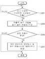
도 7은 본 발명의 일 실시 예에 따른 무선전력 중계장치(400)를 이용한 무선전력 전송 방법의 흐름도이다.7 is a flowchart illustrating a wireless power transmission method using the
먼저, 검출부(440)는 제1 영역 내에서 제1 무선전력 수신장치를 검출한다(S101). 검출부(440)는 센싱 코일을 포함할 수 있다. 센싱 코일은 각 공진 코일들의 일면에 위치할 수 있다. 여기서, 제1 영역은 제1 공진 코일(421)이 제1 무선전력 수신장치의 수신 공진 코일을 검출 할 수 있는 범위의 영역을 의미할 수 있다. 일 실시 예에서 제1 영역은 제1 공진 코일(421)이 감겨진 턴수, 제1 공진 코일의 지름, 직경 등에 따라 가변할 수 있는 범위의 영역일 수 있다.First, the
그 후, 제어부(450)는 제1 공진 코일(421)에 페어링된 제1 스위치(431)를 개방시킨다(S103). 제1 스위치(431)를 개방시키는 것은 도 6에서 도시한 바와 같이, 제1 공진 코일(421)을 회로에 연결시키는 것을 의미할 수 있다. 제1 스위치(431)가 개방되면, 송신 공진 코일(410)은 제1 공진 코일(421)에 전력을 전송하고, 제1 공진 코일(421)은 제1 무선전력 수신장치에 자기 공진에 의한 전력을 전송한다(S105).Thereafter, the
그 후, 검출부(440)는 제2 영역 내에서 제2 무선전력 수신장치를 검출한다(S107). 여기서, 제2 영역은 제2 공진 코일(422)이 제2 무선전력 수신장치의 수신 공진 코일을 검출 할 수 있는 범위의 영역을 의미할 수 있다. 일 실시 예에서 제2 영역은 제2 공진 코일(422)이 감겨진 턴수, 제2 공진 코일(422)의 지름, 직경 등에 따라 가변할 수 있는 범위의 영역일 수 있다.Thereafter, the
그 후, 제어부(450)는 제2 공진 코일(422)에 페어링된 제2 스위치(432)를 개방시킨다(S109). 제2 스위치(432)를 개방시키는 것은 도 6에서 도시한 바와 같이, 제2 공진 코일(422)을 회로에 연결시키는 것을 의미할 수 있다. 제2 스위치(432)가 개방되면, 송신 공진 코일은 제2 공진 코일(421)에 전력을 전송하고, 제2 공진 코일(421)은 제2 무선전력 수신장치에 자기 공진에 의한 전력을 전송한다(S111).
Thereafter, the
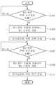
도 8은 본 발명의 일 실시 예에 따른 공진주파수 조절 방법을 나타낸 흐름도이다.8 is a flowchart illustrating a resonant frequency adjusting method according to an exemplary embodiment of the present invention.
먼저, 제어부(450)는 하나 이상의 무선전력 수신장치가 검출되었는지를 확인한다(S201). 무선전력 수신장치를 검출하는 방법은 각 공진 코일들의 일면에 센싱 코일을 설치하여 검출하는 방법과 각 스위치들을 교대로 동작시켜 공진 코일과 무선전력 수신장치 사이에 전력 전달이 일어나는지를 확인하여 검출하는 방법이 있다. 상세한 설명은 도 5 및 도 6에서 설명한 바와 같다.First, the
그 후, 제어부(450)는 각 공진 코일들에 대응하는 스위치를 회로에 직렬로 연결시킨다(S203). 무선전력 수신장치가 2개만 검출된 경우, 검출된 영역에 해당하는 2개의 공진 코일들만을 연결시킨다.Thereafter, the
그 후, 제어부(450)는 무선전력 중계장치(400)의 공진주파수가 변경되었는지 판단한다(S205). 연결된 공진 코일들에 의해 인덕턴스 값이 변경되고, 그에 따라 공진주파수도 변경될 수 있다. 공진주파수가 변경된 것으로 판단된 경우, 제어부(450)는 가변 인덕터(461)의 인덕턴스 값 및 가변 캐패시터(462)의 캐패시턴스 값을 변경시킨다(S207). 제어부(450)는 가변 인덕터(461)의 인덕턴스 값 및 가변 캐패시터(462)의 캐패시턴스 값을 변경시켜 무선전력 중계장치(400)의 공진주파수가 원래 값을 재 변경 시킨다.Thereafter, the
상기와 같이 무선전력 중계장치(400)의 가변 인덕터(461) 및 가변 커패시터(462)의 삽입을 통해 공진주파수를 지속적으로 유지할 수 있어 공진주파수가 변함에 따라 발생하는 전력전송 효율의 문제를 해결할 수 있다.
As described above, the resonant frequency can be continuously maintained by inserting the
도 9는 본 발명의 일 실시 예에 따른 루프형 공진 코일들을 포함하는 무선전력 중계장치(400)를 사용한 경우, 자기장의 세기를 검출한 시뮬레이션 결과를 나타낸 도면이다.9 is a diagram illustrating a simulation result of detecting the strength of a magnetic field when a
도 9의 시뮬레이션 결과는 전자파 해석 툴 ANSYS사의 HFSS를 사용하여 자기장의 세기를 시뮬레이션 한 결과로, 지면으로부터 10츠 떨어진 위치에서 측정된 결과이다. 시뮬레이션 결과를 살펴보면, 제1 공진 코일(421) 및 제2 공진 코일(422) 근처에만 자기장이 유기되는 것을 확인 할 수 있다.
The simulation result of FIG. 9 is the result of simulating the strength of the magnetic field using the HFSS of the electromagnetic wave analysis tool ANSYS, and is measured at a
도 10은 도 9에 도시한 무선전력 중계장치(400)의 단면에 대한 자기장의 세기를 나타낸 그래프이다.FIG. 10 is a graph showing the strength of the magnetic field with respect to the cross section of the
도 9에서 x축은 무선전력 중계장치(400) 단면의 가로 축이고, y축은 무선전력 중계장치(400) 단면의 세로 축이고, z축은 무선전력 중계장치(400) 단면의 수직방향의 축이다.In FIG. 9, the x axis is a horizontal axis of the cross section of the
도 10의 (a)는 y축의 원점에서 15cm, z축의 원점에서 10cm 떨어진 위치에서 x축의 거리에 따라 자기장의 세기를 측정한 그래프이다.10 (a) is a graph measuring the intensity of the magnetic field according to the distance of the x-axis at a
도 10의 (a)에서 도시한 바와 같이 제1 공진 코일(421)이 존재하는 곳(대략 x축으로부터 65~80cm 떨어진 곳)에서만 매우 큰 자기장이 존재하며 제1 공진 코일(421) 이외의 영역에서 자기장의 세기는 매우 작음을 확인할 수 있다.As shown in (a) of FIG. 10, a very large magnetic field exists only in a place where the first
도 10의 (b)는 x축의 원점에서 45cm, z축의 원점에서 10cm 떨어진 위치에서 y축의 거리에 따라 자기장의 세기를 측정한 그래프이다.FIG. 10B is a graph measuring the strength of the magnetic field according to the distance of the y-axis at a
도 10의 (b)에서 도시한 바와 같이 제2 공진 코일(421)이 존재하는 곳(대략 y 축으로부터 45~65cm 떨어진 곳)에서만 매우 큰 자기장이 존재하며 제2 공진 코일(422) 이외의 영역에서 자기장의 세기는 매우 작음을 확인할 수 있다.
As shown in (b) of FIG. 10, a very large magnetic field exists only in a place where the second
상술한 본 발명에 따른 공진주파수 조절 방법은 컴퓨터에서 실행되기 위한 프로그램으로 제작되어 컴퓨터가 읽을 수 있는 기록 매체에 저장될 수 있으며, 컴퓨터가 읽을 수 있는 기록 매체의 예로는 ROM, RAM, CD-ROM, 자기 테이프, 플로피디스크, 광 데이터 저장장치 등이 있으며, 또한 캐리어 웨이브(예를 들어 인터넷을 통한 전송)의 형태로 구현되는 것도 포함한다.The above-described resonant frequency adjusting method according to the present invention can be stored in a computer-readable recording medium that is produced as a program for execution on a computer, and examples of the computer-readable recording medium include ROM, RAM, CD-ROM. Magnetic tapes, floppy disks, optical data storage devices, and the like, and also include those implemented in the form of carrier waves (eg, transmission over the Internet).
컴퓨터가 읽을 수 있는 기록 매체는 네트워크로 연결된 컴퓨터 시스템에 분산되어, 분산방식으로 컴퓨터가 읽을 수 있는 코드가 저장되고 실행될 수 있다. 그리고, 상기 방법을 구현하기 위한 기능적인(function) 프로그램, 코드 및 코드 세그먼트들은 본 발명이 속하는 기술분야의 프로그래머들에 의해 용이하게 추론될 수 있다.
The computer readable recording medium may be distributed over a networked computer system so that computer readable code can be stored and executed in a distributed manner. And, functional programs, codes and code segments for implementing the above method can be easily inferred by programmers of the technical field to which the present invention belongs.
또한, 이상에서는 본 발명의 바람직한 실시예에 대하여 도시하고 설명하였지만, 본 발명은 상술한 특정의 실시예에 한정되지 아니하며, 청구범위에서 청구하는 본 발명의 요지를 벗어남이 없이 당해 발명이 속하는 기술분야에서 통상의 지식을 가진 자에 의해 다양한 변형 실시가 가능한 것은 물론이고, 이러한 변형 실시들은 본 발명의 기술적 사상이나 전망으로부터 개별적으로 이해 되어서는 안될 것이다.While the present invention has been particularly shown and described with reference to exemplary embodiments thereof, it is to be understood that the invention is not limited to the disclosed exemplary embodiments, but, on the contrary, It should be understood that various modifications may be made by those skilled in the art without departing from the spirit and scope of the present invention.
100: 전력 소스
200: 무선전력 송신장치
210: 송신 유도 코일
220: 송신 공진 코일
300: 무선전력 수신장치
310: 수신 공진 코일
320: 수신 유도 코일
330: 정류회로
340: 부하
400: 무선전력 중계장치
410: 송신 공진 코일
421: 제1 공진 코일
422: 제2 공진 코일
423: 제3 공진 코일
431: 제1 스위치
432: 제2 스위치
433: 제3 스위치
440: 검출부
450: 제어부100: Power source
200: Wireless power transmitting device
210: transmission induction coil
220: transmission resonance coil
300: Wireless power receiving device
310: Receive resonant coil
320: reception induction coil
330: rectifier circuit
340: Load
400: wireless power repeater
410: transmission resonance coil
421: first resonant coil
422: second resonant coil
423: third resonant coil
431: first switch
432: second switch
433: third switch
440: detector
450: control unit
Claims (21)
Translated fromKorean상기 무선전력 수신장치에 공진을 이용하여 전력을 전송하는 공진 코일; 및
상기 무선전력 수신장치의 근접여부를 검출하는 검출부를 포함하고,
상기 공진 코일은 복수의 공진 영역을 형성하고,
상기 무선전력 송신장치는
상기 복수의 공진 영역 중 상기 검출된 무선전력 수신장치의 위치에 대응하는 공진 영역을 스위칭을 통해 상기 검출된 무선전력 수신장치에 전력을 전송하며,
각 공진 영역은 상기 스위칭을 통해 직렬 연결 가능한 것을 특징으로 하는
무선전력 송신장치.A wireless power transmitter for wirelessly transmitting power to a wireless power receiver,
A resonance coil for transmitting power to the wireless power receiver by using resonance; And
It includes a detection unit for detecting whether the wireless power receiver close,
The resonant coil forms a plurality of resonant regions,
The wireless power transmission device
Transmitting power to the detected wireless power receiver by switching a resonance region corresponding to the position of the detected wireless power receiver among the plurality of resonance regions,
Each resonance region may be connected in series through the switching.
Wireless power transmitter.
상기 각 공진 영역은
내부 루프와
상기 내부 루프와 연결되고, 상기 내부 루프를 감싸는 형태를 갖는 외부 루프를 포함하고,
상기 내부 루프와 상기 외부 루프는 스위치 없이 직렬 연결된 것을 특징으로 하는
무선전력 송신장치.The method of claim 1,
Each resonance region is
With inner loops
An outer loop connected to the inner loop and having a shape surrounding the inner loop;
The inner loop and the outer loop are connected in series without a switch.
Wireless power transmitter.
상기 내부 루프의 권선수와 상기 외부 루프의 권선수는 동일하거나 다른 것을 특징으로 하는
무선전력 송신장치.The method of claim 2,
The number of turns of the inner loop and the number of turns of the outer loop is the same or different
Wireless power transmitter.
상기 내부 루프 및 상기 외부 루프 각각은
원형, 사각형, 타원형 중 어느 하나의 형태를 가지는 것을 특징으로 하는
무선전력 송신장치.The method of claim 2,
Each of the inner loop and the outer loop
Characterized in that it has a shape of any one of round, square, oval
Wireless power transmitter.
복수의 스위치를 더 포함하고,
상기 복수의 공진 영역 및 상기 복수의 스위치 각각은 서로 페어링된 것을 특징으로 하는
무선전력 송신장치.The method of claim 1,
Further comprising a plurality of switches,
The plurality of resonance regions and each of the plurality of switches are paired with each other.
Wireless power transmitter.
공진주파수를 일정하게 유지시키기 위한 가변 인덕터 및 가변 캐패시터를 더 포함하는 것을 특징으로 하는
무선전력 송신장치.The method of claim 1,
And further comprising a variable inductor and a variable capacitor for maintaining a constant resonant frequency.
Wireless power transmitter.
상기 무선전력 송신장치는
상기 복수의 공진 영역 중 상기 무선전력 수신장치가 검출된 공진 영역을 상기 스위칭을 통해 선택적으로 동작시키는 것을 특징으로 하는
무선전력 송신장치.The method of claim 1,
The wireless power transmission device
Characterized in that the wireless power receiving device of the plurality of resonant region to selectively detect the resonance region by the switching through
Wireless power transmitter.
멤스(MEMS) 스위치인 것을 특징으로 하는
무선전력 송신장치.The method of claim 5, wherein each switch is
MEMS switch, characterized in that
Wireless power transmitter.
상기 각 공진 영역 일측에 위치하고, 메트릭스 구조의 센싱 코일을 포함하는 것을 특징으로 하는
무선전력 송신장치.The apparatus according to claim 1,
Located on one side of each resonance region, characterized in that it comprises a sensing coil of the matrix structure
Wireless power transmitter.
제1 영역 내에서 제1 공진 코일을 통해 전력을 수신하는 제1 무선전력 수신장치를 검출하는 단계;
상기 제1 무선전력 수신장치가 검출된 경우, 상기 제1 공진 코일과 페어링되는 제1 스위치를 개방시키는 단계;
상기 제1 스위치의 개방에 따라 제1 무선전력 수신장치에 전력을 전송하는 단계;
상기 전력 전송 중 제2 영역 내에서 제2 공진 코일을 통해 전력을 수신하는 제2 무선전력 수신장치를 검출하는 단계;
상기 제2 무선전력 수신장치가 검출된 경우, 상기 제2 공진 코일과 페어링되는 제2 스위치를 개방시키는 단계; 및
상기 제2 스위치의 개방에 따라 제2 무선전력 수신장치에 전력을 전송하는 단계를 포함하는 것을 특징으로 하는 무선전력 전송 방법.In the wireless power transmission method using magnetic resonance,
Detecting a first wireless power receiver receiving power through the first resonant coil in the first region;
Opening the first switch paired with the first resonant coil when the first wireless power receiver is detected;
Transmitting power to a first wireless power receiver according to the opening of the first switch;
Detecting a second wireless power receiver receiving power through a second resonant coil in a second area of the power transmission;
Opening a second switch paired with the second resonant coil when the second wireless power receiver is detected; And
And transmitting power to a second wireless power receiver according to the opening of the second switch.
상기 제1,2 무선전력 수신장치를 검출하는 단계는,
주기적인 구동신호를 상기 제1,2 스위치에 순차적으로 전달하여 제1,2 무선전력 수신장치를 검출하는 것을 특징으로 하는 무선전력 전송 방법.12. The method of claim 11,
Detecting the first and second wireless power receivers,
And transmitting the periodic driving signal to the first and second switches sequentially to detect the first and second wireless power receivers.
상기 제1 영역은 상기 제1 공진 코일이 상기 제1 무선전력 수신장치를 검출할 수 있는 범위의 영역이고,
상기 제2 영역은 상기 제2 공진 코일이 상기 제2 무선전력 수신장치를 검출할 수 있는 범위의 영역인 것을 특징으로 하는 무선전력 전송 방법.12. The method of claim 11,
The first area is an area in which the first resonant coil can detect the first wireless power receiver.
The second area is a wireless power transmission method, characterized in that the second resonant coil is an area of the range that can detect the second wireless power receiver.
상기 제1,2 공진 코일이 감겨진 턴수, 상기 제1,2 공진 코일의 지름, 직경에 따라 가변할 수 있는 범위인 것을 특징으로 하는 무선전력 전송 방법.The method of claim 13, wherein the first and second regions,
And a range in which the first and second resonant coils are wound, the diameter of the first and second resonant coils, and the diameter of the first and second resonant coils.
하나의 도선으로 한 번 이상 감겨진 루프형태를 가지는 것을 특징으로 하는 무선전력 전송 방법.The method of claim 11, wherein each of the first and second resonant coils,
Wireless power transmission method characterized in that it has a loop form wound one or more times with one wire.
원형, 사각형, 타원형 중 어느 하나의 형태를 가지는 것을 특징으로 하는 무선전력 전송 방법.The method of claim 15, wherein the loop form
Wireless power transmission method characterized in that it has any one of a circle, a rectangle, an ellipse.
외부 루프와 내부 루프를 가지고, 상기 외부 루프 및 상기 내부 루프의 감겨진 횟수는 동일하거나 다른 것을 특징으로 하는 무선전력 전송 방법.The method of claim 11, wherein each of the first and second resonant coils,
And an outer loop and an inner loop, wherein the number of turns of the outer loop and the inner loop is the same or different.
상기 제1,2 스위치들은,
멤스(MEMS) 스위치로 구성되는 것을 특징으로 하는 무선전력 전송 방법.12. The method of claim 11,
The first and second switches,
Wireless power transmission method comprising a MEMS (MEMS) switch.
상기 무선전력 중계장치는, 송신 공진 코일, 복수의 공진 코일들, 상기 복수의 공진 코일들과 페어링된 복수의 스위치들을 포함하고,
하나 이상의 무선전력 수신장치를 검출하는 단계;
상기 검출된 하나 이상의 무선전력 수신장치에 전력을 전달하는 상기 복수의 공진 코일들을 상기 복수의 스위치들을 통해 상기 송신 공진 코일과 연결시키는 단계;
상기 무선전력 중계장치의 공진주파수가 변경되었는지 판단하는 단계;
상기 판단결과, 상기 공진주파수가 변경된 경우, 원래의 공진주파수로 재 변경시키는 단계를 포함하는 것을 특징으로 하는 공진주파수 조절 방법.In the resonance frequency control method of the wireless power repeater using magnetic resonance,
The wireless power repeater includes a transmission resonant coil, a plurality of resonant coils, a plurality of switches paired with the plurality of resonant coils,
Detecting at least one wireless power receiver;
Coupling the plurality of resonant coils for transmitting power to the detected one or more wireless power receivers with the transmission resonant coils through the plurality of switches;
Determining whether a resonant frequency of the wireless power repeater has been changed;
And re-changing the original resonant frequency when the resonant frequency is changed as a result of the determination.
가변 인덕터 및 가변 캐패시터를 이용하여 원래의 공진주파수로 재변경시키는 단계를 포함하는 것을 특징으로 하는 공진주파수 조절 방법.The method of claim 19, wherein when the resonance frequency is changed as a result of the determination, changing the original resonance frequency back to
And changing back to the original resonant frequency using the variable inductor and the variable capacitor.
A computer-readable recording medium produced by a program for executing a method according to any one of claims 19 to 20 as a computer.
Priority Applications (5)
| Application Number | Priority Date | Filing Date | Title |
|---|---|---|---|
| KR1020110124419AKR101305823B1 (en) | 2011-11-25 | 2011-11-25 | Apparatus for relaying wireless power, method for transmitting wireless power and method for contorlling resonance frequency |
| EP12192314.8AEP2597782B1 (en) | 2011-11-25 | 2012-11-13 | Wireless power transmitter and method of transmitting power thereof |
| TW101142231ATWI559340B (en) | 2011-11-25 | 2012-11-13 | Wireless power transmitter and method of transmitting power thereof |
| US13/685,305US9287736B2 (en) | 2011-11-25 | 2012-11-26 | Wireless power transmitter and method of transmitting power thereof |
| CN201210488498.1ACN103138406B (en) | 2011-11-25 | 2012-11-26 | Wireless power conveyer and the method transmitting electric power thereof |
Applications Claiming Priority (1)
| Application Number | Priority Date | Filing Date | Title |
|---|---|---|---|
| KR1020110124419AKR101305823B1 (en) | 2011-11-25 | 2011-11-25 | Apparatus for relaying wireless power, method for transmitting wireless power and method for contorlling resonance frequency |
Publications (2)
| Publication Number | Publication Date |
|---|---|
| KR20130058423A KR20130058423A (en) | 2013-06-04 |
| KR101305823B1true KR101305823B1 (en) | 2013-09-06 |
Family
ID=47257482
Family Applications (1)
| Application Number | Title | Priority Date | Filing Date |
|---|---|---|---|
| KR1020110124419AExpired - Fee RelatedKR101305823B1 (en) | 2011-11-25 | 2011-11-25 | Apparatus for relaying wireless power, method for transmitting wireless power and method for contorlling resonance frequency |
Country Status (5)
| Country | Link |
|---|---|
| US (1) | US9287736B2 (en) |
| EP (1) | EP2597782B1 (en) |
| KR (1) | KR101305823B1 (en) |
| CN (1) | CN103138406B (en) |
| TW (1) | TWI559340B (en) |
Cited By (2)
| Publication number | Priority date | Publication date | Assignee | Title |
|---|---|---|---|---|
| CN103545940A (en)* | 2013-11-11 | 2014-01-29 | 天津工业大学 | Asymmetric in-line wireless power coupler |
| KR101880267B1 (en) | 2017-02-07 | 2018-07-23 | (주)그린파워 | current collector converter switching method for broad resonance frequency allowed of wireless power transfer |
Families Citing this family (25)
| Publication number | Priority date | Publication date | Assignee | Title |
|---|---|---|---|---|
| KR101984811B1 (en) | 2012-10-23 | 2019-06-03 | 삼성전자주식회사 | Field controllable 3d flexible resonator for wireless power transfer system |
| US9362776B2 (en)* | 2012-11-27 | 2016-06-07 | Qualcomm Incorporated | Wireless charging systems and methods |
| US20140159673A1 (en)* | 2012-12-07 | 2014-06-12 | Samsung Electronics Co., Ltd. | Wireless charging apparatus and method |
| US20150091523A1 (en)* | 2013-10-02 | 2015-04-02 | Mediatek Singapore Pte. Ltd. | Wireless charger system that has variable power / adaptive load modulation |
| WO2015060570A1 (en)* | 2013-10-23 | 2015-04-30 | Lg Electronics Inc. | Wireless power transfer method, apparatus and system |
| US20160308393A1 (en)* | 2013-11-11 | 2016-10-20 | Powerbyproxi Limited | Contactless power receiver and method for operating same |
| US20150249343A1 (en) | 2014-03-03 | 2015-09-03 | The Wiremold Company | Wireless power stations |
| US11984731B2 (en)* | 2014-12-22 | 2024-05-14 | The Wiremold Company | Ecosystem for surface-based wireless charging system |
| EP3204999A4 (en)* | 2014-10-06 | 2018-06-13 | Robert Bosch GmbH | Wireless charging system for devices in a vehicle |
| US9742203B2 (en)* | 2014-10-20 | 2017-08-22 | Qualcomm Incorporated | Distributed resonators for wireless power transfer |
| KR20160051497A (en)* | 2014-11-03 | 2016-05-11 | 주식회사 한림포스텍 | Method and apparutus for controlling a power transmission coverage of wireless power transmission network |
| US10110018B2 (en) | 2014-12-23 | 2018-10-23 | Intel Corporation | Wireless power repeating |
| JP2016220421A (en)* | 2015-05-21 | 2016-12-22 | トヨタ自動車株式会社 | Non-contact power transmission device and power transmission system |
| US20160352133A1 (en)* | 2015-05-26 | 2016-12-01 | Intel Corporation | Wireless power transmitting coil disposed at an input device |
| US10714960B2 (en)* | 2015-12-22 | 2020-07-14 | Intel Corporation | Uniform wireless charging device |
| US10097046B2 (en)* | 2016-03-18 | 2018-10-09 | Global Energy Transmission, Co. | Wireless power assembly |
| US10000133B2 (en) | 2016-04-20 | 2018-06-19 | Qualcomm Incorporated | Systems and methods for identifying an ideal operation frequency for wireless power transfer |
| KR102560030B1 (en) | 2016-05-27 | 2023-07-26 | 삼성전자주식회사 | Wireless power receiver and method thereof |
| KR102621925B1 (en)* | 2016-11-01 | 2024-01-09 | 한국전자통신연구원 | An wireless power apparatuse using multiple receiving coils for efficiency and system including the same |
| KR20180101070A (en) | 2017-03-03 | 2018-09-12 | 삼성전기주식회사 | Coil module and wireless power transmitter using the same |
| KR102439878B1 (en)* | 2017-04-12 | 2022-09-05 | 삼성전자주식회사 | Wireless power transmitting device, electronic device for wirelessly receiving power and operation method thereof |
| US11641134B2 (en) | 2017-04-14 | 2023-05-02 | General Electric Company | Wireless charging device and a method for detecting a receiver device |
| KR102407897B1 (en)* | 2017-04-28 | 2022-06-13 | 삼성전자주식회사 | Wireless power transmitting device and electronic device for wirelessly receiving power |
| JP6802607B2 (en)* | 2017-11-20 | 2020-12-16 | 昭和飛行機工業株式会社 | Non-contact power supply device |
| US11159056B2 (en)* | 2019-09-12 | 2021-10-26 | Spark Connected LLC | Wireless power receiver circuit and method |
Citations (2)
| Publication number | Priority date | Publication date | Assignee | Title |
|---|---|---|---|---|
| KR20110019772A (en)* | 2011-02-14 | 2011-02-28 | 자동차부품연구원 | Transmitter receiver for a electric car and the electric power source system |
| KR20110062841A (en)* | 2009-12-04 | 2011-06-10 | 한국전자통신연구원 | Wireless power transmitter |
Family Cites Families (12)
| Publication number | Priority date | Publication date | Assignee | Title |
|---|---|---|---|---|
| FR2809235A1 (en)* | 2000-05-17 | 2001-11-23 | St Microelectronics Sa | ANTENNA FOR GENERATING AN ELECTROMAGNETIC FIELD FOR TRANSPONDER |
| JP3636113B2 (en) | 2001-08-10 | 2005-04-06 | オムロン株式会社 | Portable communication device, monitoring device, monitoring system, control program for portable communication device, control program for monitoring device, recording medium recording control program for portable communication device, and recording medium recording control program for monitoring device |
| EP2067148B1 (en)* | 2006-09-18 | 2011-06-29 | Philips Intellectual Property & Standards GmbH | An apparatus, a system and a method for enabling electromagnetic energy transfer |
| US8030888B2 (en)* | 2007-08-13 | 2011-10-04 | Pandya Ravi A | Wireless charging system for vehicles |
| KR20130025444A (en)* | 2008-07-17 | 2013-03-11 | 퀄컴 인코포레이티드 | Adaptive matching and tuning of hf wireless power transmit antenna |
| KR101088401B1 (en) | 2008-08-29 | 2011-12-01 | 안동대학교 산학협력단 | Wireless power transmitter |
| US8772973B2 (en)* | 2008-09-27 | 2014-07-08 | Witricity Corporation | Integrated resonator-shield structures |
| AU2010234396A1 (en)* | 2009-04-08 | 2011-10-27 | Access Business Group International Llc | Selectable coil array |
| CA2768397A1 (en)* | 2009-07-24 | 2011-01-27 | Access Business Group International Llc | Power supply |
| US8934857B2 (en)* | 2010-05-14 | 2015-01-13 | Qualcomm Incorporated | Controlling field distribution of a wireless power transmitter |
| CN102048367B (en)* | 2010-10-09 | 2013-01-02 | 惠州市德赛视听科技有限公司 | Wireless power supply desktop |
| WO2014111817A2 (en)* | 2013-01-06 | 2014-07-24 | Glenn Gulak | Method and system for maximum achievable efficiency in near-field coupled wireless power transfer systems |
- 2011
- 2011-11-25KRKR1020110124419Apatent/KR101305823B1/ennot_activeExpired - Fee Related
- 2012
- 2012-11-13EPEP12192314.8Apatent/EP2597782B1/enactiveActive
- 2012-11-13TWTW101142231Apatent/TWI559340B/enactive
- 2012-11-26CNCN201210488498.1Apatent/CN103138406B/enactiveActive
- 2012-11-26USUS13/685,305patent/US9287736B2/ennot_activeExpired - Fee Related
Patent Citations (2)
| Publication number | Priority date | Publication date | Assignee | Title |
|---|---|---|---|---|
| KR20110062841A (en)* | 2009-12-04 | 2011-06-10 | 한국전자통신연구원 | Wireless power transmitter |
| KR20110019772A (en)* | 2011-02-14 | 2011-02-28 | 자동차부품연구원 | Transmitter receiver for a electric car and the electric power source system |
Cited By (2)
| Publication number | Priority date | Publication date | Assignee | Title |
|---|---|---|---|---|
| CN103545940A (en)* | 2013-11-11 | 2014-01-29 | 天津工业大学 | Asymmetric in-line wireless power coupler |
| KR101880267B1 (en) | 2017-02-07 | 2018-07-23 | (주)그린파워 | current collector converter switching method for broad resonance frequency allowed of wireless power transfer |
Also Published As
| Publication number | Publication date |
|---|---|
| US20130134794A1 (en) | 2013-05-30 |
| TWI559340B (en) | 2016-11-21 |
| TW201338332A (en) | 2013-09-16 |
| CN103138406B (en) | 2016-08-03 |
| KR20130058423A (en) | 2013-06-04 |
| CN103138406A (en) | 2013-06-05 |
| EP2597782A1 (en) | 2013-05-29 |
| US9287736B2 (en) | 2016-03-15 |
| EP2597782B1 (en) | 2019-01-02 |
Similar Documents
| Publication | Publication Date | Title |
|---|---|---|
| KR101305823B1 (en) | Apparatus for relaying wireless power, method for transmitting wireless power and method for contorlling resonance frequency | |
| CN102484397B (en) | Wireless power transmission device | |
| KR101859191B1 (en) | Method and apparatus for controlling wireless power transmission and reception, and wireless power transmission system | |
| KR101241481B1 (en) | A wireless power transmission apparatus and method thereof | |
| JP4911148B2 (en) | Contactless power supply | |
| US20180054086A1 (en) | Method and device for adjusting position of coils in wireless power transmission system | |
| US11770027B2 (en) | Wireless power transmission device | |
| JP2013545430A (en) | Electronic device power supply method, source electronic device and target electronic device using the same | |
| TW201433039A (en) | Wireless power receiver and method of controlling the same | |
| KR20100042292A (en) | Long range low frequency resonator and materials | |
| KR20140093318A (en) | Apparatus for power and data transmission and data reception using mutual resonance, apparatus for power and data reception and data transmission using mutual resonance, method thereof | |
| KR20120127231A (en) | Apparatus and method for wireless power transmission | |
| KR20150032366A (en) | Resonator device with improved isoalation for stable wireless power transfer | |
| KR101659183B1 (en) | Wireless power transmitter and wireless power transmitting system | |
| US10291067B2 (en) | Computer modeling for resonant power transfer systems | |
| KR20140076993A (en) | Wireless power device | |
| KR20130033837A (en) | A wireless power transmission apparatus and method thereof | |
| KR102041988B1 (en) | Wireless power transfer device | |
| KR101241659B1 (en) | Apparatus for transmitting wireless power and method for transmitting wireless power | |
| KR20150055755A (en) | Hybrid wireless power transmission device which enables to transmit resonance power signal and induced power signal simultaneously and hybrid wireless power transmission system including the same | |
| KR101952604B1 (en) | Method and apparatus for controlling wireless power transmission and reception, and wireless power transmission system | |
| KR101883684B1 (en) | Apparatus and method for transmitting wireless power using resonant coupling therefor system | |
| KR20140014502A (en) | Wiress power transmission apparatus and method for constructing wiress charging space using the same | |
| KR20150143146A (en) | Method and apparatus of wireless power charging |
Legal Events
| Date | Code | Title | Description |
|---|---|---|---|
| A201 | Request for examination | ||
| PA0109 | Patent application | St.27 status event code:A-0-1-A10-A12-nap-PA0109 | |
| PA0201 | Request for examination | St.27 status event code:A-1-2-D10-D11-exm-PA0201 | |
| E902 | Notification of reason for refusal | ||
| PE0902 | Notice of grounds for rejection | St.27 status event code:A-1-2-D10-D21-exm-PE0902 | |
| E13-X000 | Pre-grant limitation requested | St.27 status event code:A-2-3-E10-E13-lim-X000 | |
| P11-X000 | Amendment of application requested | St.27 status event code:A-2-2-P10-P11-nap-X000 | |
| P13-X000 | Application amended | St.27 status event code:A-2-2-P10-P13-nap-X000 | |
| PG1501 | Laying open of application | St.27 status event code:A-1-1-Q10-Q12-nap-PG1501 | |
| E701 | Decision to grant or registration of patent right | ||
| PE0701 | Decision of registration | St.27 status event code:A-1-2-D10-D22-exm-PE0701 | |
| GRNT | Written decision to grant | ||
| PR0701 | Registration of establishment | St.27 status event code:A-2-4-F10-F11-exm-PR0701 | |
| PR1002 | Payment of registration fee | St.27 status event code:A-2-2-U10-U11-oth-PR1002 Fee payment year number:1 | |
| PG1601 | Publication of registration | St.27 status event code:A-4-4-Q10-Q13-nap-PG1601 | |
| PN2301 | Change of applicant | St.27 status event code:A-5-5-R10-R13-asn-PN2301 St.27 status event code:A-5-5-R10-R11-asn-PN2301 | |
| PN2301 | Change of applicant | St.27 status event code:A-5-5-R10-R13-asn-PN2301 St.27 status event code:A-5-5-R10-R11-asn-PN2301 | |
| FPAY | Annual fee payment | Payment date:20160805 Year of fee payment:4 | |
| PR1001 | Payment of annual fee | St.27 status event code:A-4-4-U10-U11-oth-PR1001 Fee payment year number:4 | |
| R18-X000 | Changes to party contact information recorded | St.27 status event code:A-5-5-R10-R18-oth-X000 | |
| FPAY | Annual fee payment | Payment date:20170804 Year of fee payment:5 | |
| PR1001 | Payment of annual fee | St.27 status event code:A-4-4-U10-U11-oth-PR1001 Fee payment year number:5 | |
| R18-X000 | Changes to party contact information recorded | St.27 status event code:A-5-5-R10-R18-oth-X000 | |
| FPAY | Annual fee payment | Payment date:20180809 Year of fee payment:6 | |
| PR1001 | Payment of annual fee | St.27 status event code:A-4-4-U10-U11-oth-PR1001 Fee payment year number:6 | |
| P22-X000 | Classification modified | St.27 status event code:A-4-4-P10-P22-nap-X000 | |
| P22-X000 | Classification modified | St.27 status event code:A-4-4-P10-P22-nap-X000 | |
| FPAY | Annual fee payment | Payment date:20190812 Year of fee payment:7 | |
| PR1001 | Payment of annual fee | St.27 status event code:A-4-4-U10-U11-oth-PR1001 Fee payment year number:7 | |
| R18-X000 | Changes to party contact information recorded | St.27 status event code:A-5-5-R10-R18-oth-X000 | |
| R18-X000 | Changes to party contact information recorded | St.27 status event code:A-5-5-R10-R18-oth-X000 | |
| PR1001 | Payment of annual fee | St.27 status event code:A-4-4-U10-U11-oth-PR1001 Fee payment year number:8 | |
| PN2301 | Change of applicant | St.27 status event code:A-5-5-R10-R13-asn-PN2301 St.27 status event code:A-5-5-R10-R11-asn-PN2301 | |
| P22-X000 | Classification modified | St.27 status event code:A-4-4-P10-P22-nap-X000 | |
| PC1903 | Unpaid annual fee | St.27 status event code:A-4-4-U10-U13-oth-PC1903 Not in force date:20210903 Payment event data comment text:Termination Category : DEFAULT_OF_REGISTRATION_FEE | |
| PC1903 | Unpaid annual fee | St.27 status event code:N-4-6-H10-H13-oth-PC1903 Ip right cessation event data comment text:Termination Category : DEFAULT_OF_REGISTRATION_FEE Not in force date:20210903 | |
| R18-X000 | Changes to party contact information recorded | St.27 status event code:A-5-5-R10-R18-oth-X000 | |
| P22-X000 | Classification modified | St.27 status event code:A-4-4-P10-P22-nap-X000 |