KR101305602B1 - Motion Recognition Apparatus for Switches of Vehicles - Google Patents
Motion Recognition Apparatus for Switches of VehiclesDownload PDFInfo
- Publication number
- KR101305602B1 KR101305602B1KR1020110061401AKR20110061401AKR101305602B1KR 101305602 B1KR101305602 B1KR 101305602B1KR 1020110061401 AKR1020110061401 AKR 1020110061401AKR 20110061401 AKR20110061401 AKR 20110061401AKR 101305602 B1KR101305602 B1KR 101305602B1
- Authority
- KR
- South Korea
- Prior art keywords
- unit
- motion recognition
- signal
- switch
- vehicle
- Prior art date
- Legal status (The legal status is an assumption and is not a legal conclusion. Google has not performed a legal analysis and makes no representation as to the accuracy of the status listed.)
- Active
Links
Images


Classifications
- B—PERFORMING OPERATIONS; TRANSPORTING
- B60—VEHICLES IN GENERAL
- B60K—ARRANGEMENT OR MOUNTING OF PROPULSION UNITS OR OF TRANSMISSIONS IN VEHICLES; ARRANGEMENT OR MOUNTING OF PLURAL DIVERSE PRIME-MOVERS IN VEHICLES; AUXILIARY DRIVES FOR VEHICLES; INSTRUMENTATION OR DASHBOARDS FOR VEHICLES; ARRANGEMENTS IN CONNECTION WITH COOLING, AIR INTAKE, GAS EXHAUST OR FUEL SUPPLY OF PROPULSION UNITS IN VEHICLES
- B60K35/00—Instruments specially adapted for vehicles; Arrangement of instruments in or on vehicles
- B60K35/80—Arrangements for controlling instruments
- B—PERFORMING OPERATIONS; TRANSPORTING
- B60—VEHICLES IN GENERAL
- B60K—ARRANGEMENT OR MOUNTING OF PROPULSION UNITS OR OF TRANSMISSIONS IN VEHICLES; ARRANGEMENT OR MOUNTING OF PLURAL DIVERSE PRIME-MOVERS IN VEHICLES; AUXILIARY DRIVES FOR VEHICLES; INSTRUMENTATION OR DASHBOARDS FOR VEHICLES; ARRANGEMENTS IN CONNECTION WITH COOLING, AIR INTAKE, GAS EXHAUST OR FUEL SUPPLY OF PROPULSION UNITS IN VEHICLES
- B60K35/00—Instruments specially adapted for vehicles; Arrangement of instruments in or on vehicles
- B60K35/10—Input arrangements, i.e. from user to vehicle, associated with vehicle functions or specially adapted therefor
- B—PERFORMING OPERATIONS; TRANSPORTING
- B60—VEHICLES IN GENERAL
- B60K—ARRANGEMENT OR MOUNTING OF PROPULSION UNITS OR OF TRANSMISSIONS IN VEHICLES; ARRANGEMENT OR MOUNTING OF PLURAL DIVERSE PRIME-MOVERS IN VEHICLES; AUXILIARY DRIVES FOR VEHICLES; INSTRUMENTATION OR DASHBOARDS FOR VEHICLES; ARRANGEMENTS IN CONNECTION WITH COOLING, AIR INTAKE, GAS EXHAUST OR FUEL SUPPLY OF PROPULSION UNITS IN VEHICLES
- B60K35/00—Instruments specially adapted for vehicles; Arrangement of instruments in or on vehicles
- B60K35/20—Output arrangements, i.e. from vehicle to user, associated with vehicle functions or specially adapted therefor
- B60K35/21—Output arrangements, i.e. from vehicle to user, associated with vehicle functions or specially adapted therefor using visual output, e.g. blinking lights or matrix displays
- B60K35/22—Display screens
- B—PERFORMING OPERATIONS; TRANSPORTING
- B60—VEHICLES IN GENERAL
- B60K—ARRANGEMENT OR MOUNTING OF PROPULSION UNITS OR OF TRANSMISSIONS IN VEHICLES; ARRANGEMENT OR MOUNTING OF PLURAL DIVERSE PRIME-MOVERS IN VEHICLES; AUXILIARY DRIVES FOR VEHICLES; INSTRUMENTATION OR DASHBOARDS FOR VEHICLES; ARRANGEMENTS IN CONNECTION WITH COOLING, AIR INTAKE, GAS EXHAUST OR FUEL SUPPLY OF PROPULSION UNITS IN VEHICLES
- B60K35/00—Instruments specially adapted for vehicles; Arrangement of instruments in or on vehicles
- B60K35/20—Output arrangements, i.e. from vehicle to user, associated with vehicle functions or specially adapted therefor
- B60K35/28—Output arrangements, i.e. from vehicle to user, associated with vehicle functions or specially adapted therefor characterised by the type of the output information, e.g. video entertainment or vehicle dynamics information; characterised by the purpose of the output information, e.g. for attracting the attention of the driver
- G—PHYSICS
- G06—COMPUTING OR CALCULATING; COUNTING
- G06F—ELECTRIC DIGITAL DATA PROCESSING
- G06F3/00—Input arrangements for transferring data to be processed into a form capable of being handled by the computer; Output arrangements for transferring data from processing unit to output unit, e.g. interface arrangements
- G06F3/01—Input arrangements or combined input and output arrangements for interaction between user and computer
- G06F3/017—Gesture based interaction, e.g. based on a set of recognized hand gestures
- G—PHYSICS
- G06—COMPUTING OR CALCULATING; COUNTING
- G06F—ELECTRIC DIGITAL DATA PROCESSING
- G06F3/00—Input arrangements for transferring data to be processed into a form capable of being handled by the computer; Output arrangements for transferring data from processing unit to output unit, e.g. interface arrangements
- G06F3/01—Input arrangements or combined input and output arrangements for interaction between user and computer
- G06F3/03—Arrangements for converting the position or the displacement of a member into a coded form
- G06F3/041—Digitisers, e.g. for touch screens or touch pads, characterised by the transducing means
- G06F3/0412—Digitisers structurally integrated in a display
- G—PHYSICS
- G06—COMPUTING OR CALCULATING; COUNTING
- G06F—ELECTRIC DIGITAL DATA PROCESSING
- G06F3/00—Input arrangements for transferring data to be processed into a form capable of being handled by the computer; Output arrangements for transferring data from processing unit to output unit, e.g. interface arrangements
- G06F3/01—Input arrangements or combined input and output arrangements for interaction between user and computer
- G06F3/048—Interaction techniques based on graphical user interfaces [GUI]
- G06F3/0487—Interaction techniques based on graphical user interfaces [GUI] using specific features provided by the input device, e.g. functions controlled by the rotation of a mouse with dual sensing arrangements, or of the nature of the input device, e.g. tap gestures based on pressure sensed by a digitiser
- G06F3/0488—Interaction techniques based on graphical user interfaces [GUI] using specific features provided by the input device, e.g. functions controlled by the rotation of a mouse with dual sensing arrangements, or of the nature of the input device, e.g. tap gestures based on pressure sensed by a digitiser using a touch-screen or digitiser, e.g. input of commands through traced gestures
- G06F3/04883—Interaction techniques based on graphical user interfaces [GUI] using specific features provided by the input device, e.g. functions controlled by the rotation of a mouse with dual sensing arrangements, or of the nature of the input device, e.g. tap gestures based on pressure sensed by a digitiser using a touch-screen or digitiser, e.g. input of commands through traced gestures for inputting data by handwriting, e.g. gesture or text
- G—PHYSICS
- G06—COMPUTING OR CALCULATING; COUNTING
- G06F—ELECTRIC DIGITAL DATA PROCESSING
- G06F3/00—Input arrangements for transferring data to be processed into a form capable of being handled by the computer; Output arrangements for transferring data from processing unit to output unit, e.g. interface arrangements
- G06F3/14—Digital output to display device ; Cooperation and interconnection of the display device with other functional units
- B—PERFORMING OPERATIONS; TRANSPORTING
- B60—VEHICLES IN GENERAL
- B60K—ARRANGEMENT OR MOUNTING OF PROPULSION UNITS OR OF TRANSMISSIONS IN VEHICLES; ARRANGEMENT OR MOUNTING OF PLURAL DIVERSE PRIME-MOVERS IN VEHICLES; AUXILIARY DRIVES FOR VEHICLES; INSTRUMENTATION OR DASHBOARDS FOR VEHICLES; ARRANGEMENTS IN CONNECTION WITH COOLING, AIR INTAKE, GAS EXHAUST OR FUEL SUPPLY OF PROPULSION UNITS IN VEHICLES
- B60K2360/00—Indexing scheme associated with groups B60K35/00 or B60K37/00 relating to details of instruments or dashboards
- B60K2360/143—Touch sensitive instrument input devices
- B60K2360/1446—Touch switches
- B—PERFORMING OPERATIONS; TRANSPORTING
- B60—VEHICLES IN GENERAL
- B60K—ARRANGEMENT OR MOUNTING OF PROPULSION UNITS OR OF TRANSMISSIONS IN VEHICLES; ARRANGEMENT OR MOUNTING OF PLURAL DIVERSE PRIME-MOVERS IN VEHICLES; AUXILIARY DRIVES FOR VEHICLES; INSTRUMENTATION OR DASHBOARDS FOR VEHICLES; ARRANGEMENTS IN CONNECTION WITH COOLING, AIR INTAKE, GAS EXHAUST OR FUEL SUPPLY OF PROPULSION UNITS IN VEHICLES
- B60K2360/00—Indexing scheme associated with groups B60K35/00 or B60K37/00 relating to details of instruments or dashboards
- B60K2360/146—Instrument input by gesture
Landscapes
- Engineering & Computer Science (AREA)
- Theoretical Computer Science (AREA)
- General Engineering & Computer Science (AREA)
- Chemical & Material Sciences (AREA)
- Combustion & Propulsion (AREA)
- Transportation (AREA)
- Mechanical Engineering (AREA)
- Human Computer Interaction (AREA)
- Physics & Mathematics (AREA)
- General Physics & Mathematics (AREA)
- Switches That Are Operated By Magnetic Or Electric Fields (AREA)
Abstract
Translated fromKoreanDescription
Translated fromKorean본 발명은 차량 스위치용 모션 인식장치에 관한 것으로서, 더욱 상세하게는 차량의 주행장치, 조명장치 및 편의장치 등의 작동과 작동상태를 운전자가 스위치를 보지 않고 사용자의 접촉에 따라 작동시킬 수 있는 차량 스위치용 모션 인식장치에 관한 것이다.
The present invention relates to a motion recognition device for a vehicle switch, and more particularly, a vehicle capable of operating an operation and an operation state of a traveling device, a lighting device, and a convenience device of a vehicle according to a user's contact without looking at a switch. It relates to a motion recognition device for a switch.
일반적으로 차량의 내부에는 방향지시등, 와이퍼 등을 제어하기 위한 스위치 또는 윈도우 스위치 등과 같이 차량 주행시 자주 사용하게 되는 스위치 외에 주행의 안전성 및 운전자의 편의를 위해 다양한 스위치가 그 용도에 따라 기계적으로 작동하도록 구비되어 있다.In general, in addition to the switches frequently used when driving a vehicle, such as a switch or window switch for controlling a direction indicator, a wiper, etc., various switches are mechanically operated according to their purpose for safety of driving and driver's convenience. It is.
더욱이, 특정 차량의 경우 차량의 내부 조명이나 안개등 또한 별도로 스위치를 구비시켜 조작 가능하도록 구성할 수 있다.In addition, in the case of a specific vehicle, the interior lights or fog lights of the vehicle may also be configured to be operated by separately providing a switch.
이와 같은 스위치들 중 일부는 그 기능이 수행되고 있는 상태를 확인하기 위해 스위치가 구비된 각각의 위치를 찾아 직접 그 상태를 확인해야 한다.Some of these switches must find their own position by looking at each position where the switch is provided to confirm the state in which the function is being performed.
그러나 운전자가 차량운전 중에 스위치를 작동시키기 위해서는 여러 부분으로 분산되어 있는 각각의 스위치로 손을 뻗어야하고, 스위치의 상태를 눈으로 확인한 후 작동시켜야 하므로 차량 운전자가 운전에 집중하지 못하는 원인을 제공하는 문제점이 있었다.
However, in order for the driver to operate the switch while driving the vehicle, the driver must reach out to each switch distributed in several parts, and the driver must check the state of the switch and operate the switch, which causes the driver to concentrate on driving. There was a problem.
전술한 문제점을 해결하기 위한 본 발명이 이루고자 하는 기술적 과제는, 운전자가 스위치를 보지 않고 사용자의 접촉에 따라 작동시킬 수 있도록 모션 인식장치를 구비함으로써 주행의 안전성 및 운전자의 편의를 증대시킨 차량 스위치용 모션 인식장치를 제공하기 위한 것이다.
The technical problem to be solved by the present invention for solving the above-mentioned problems, the vehicle switch for increasing the safety of the driver and the driver's convenience by providing a motion recognition device to enable the driver to operate according to the user's contact without looking at the switch It is to provide a motion recognition device.
전술한 기술적 과제를 달성하기 위한 수단으로서, 본 발명인 차량 스위치용 모션 인식장치는 사용자의 접촉을 감지하여 감지된 신호를 입력하는 모션 인식부; 및 상기 모션 인식부로부터 감지된 신호를 바탕으로 사용자가 인식할 수 있도록 정보를 출력하는 디스플레이부; 및 상기 디스플레이부와 모션인식부에 연결설치되어 입력된 신호에 따라 해당 작동신호를 차량으로 제공하는 동시에, 작동신호에 따른 해당 장치의 작동상태 또는 차량으로부터 제공되는 정보를 디스플레이부에 출력하는 제어부를 포함한다.
As a means for achieving the above-described technical problem, a motion recognition apparatus for a vehicle switch of the present invention includes a motion recognition unit for detecting a user's touch and inputs a detected signal; And a display unit for outputting information for the user to recognize based on the signal detected by the motion recognition unit. And a control unit connected to the display unit and the motion recognition unit to provide a corresponding operation signal to the vehicle according to the input signal, and to output the operation state of the corresponding device or information provided from the vehicle to the display unit according to the input signal. Include.
본 발명에 따른 모션 인식장치는 다양한 스위치를 하나의 장치로 통합한 차량용 스위치의 작동신호를 사용자의 접촉을 인식할 수 있는 장치로 입력 가능하도록 할 수 있다.
The motion recognition apparatus according to the present invention may enable input of an operation signal of a vehicle switch incorporating various switches into one device to a device capable of recognizing a user's contact.
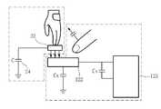
도 1은 본 발명에 따른 차량 스위치용 모션 인식장치를 도시한 도면.
도 2는 본 발명에 따른 모션 인식부를 도시한 사시도.
도 3은 본 발명에 따른 모션 인식장치의 센싱 센싱부의 작용을 나타내는 구성도,
도 4는 본 발명에 따른 모션 인식장치를 구성하는 정전용량형 터치 센싱부의 회로도,
도 5는 본 발명에 따른 모션 인식장치를 구성하는 정전용량형 터치 센싱부의 다른 회로도,
도 6은 본 발명에 따른 모션 인식장치의 사용상태를 나타내는 도이다.1 is a view showing a motion recognition device for a vehicle switch according to the present invention.
2 is a perspective view showing a motion recognition unit according to the present invention.
3 is a configuration diagram showing an operation of a sensing sensing unit of a motion recognition apparatus according to the present invention;
4 is a circuit diagram of a capacitive touch sensing unit constituting a motion recognition apparatus according to the present invention;
5 is another circuit diagram of the capacitive touch sensing unit constituting the motion recognition apparatus according to the present invention;
6 is a view showing a state of use of the motion recognition apparatus according to the present invention.
이와 같은 목적과 효과를 가지는 본 발명인 차량 스위치용 모션 인식장치는 사용자의 접촉을 감지하여 감지된 신호를 입력하는 모션 인식부; 및 상기 모션 인식부로부터 감지된 신호를 바탕으로 사용자가 인식할 수 있도록 정보를 출력하는 디스플레이부; 및 상기 디스플레이부와 모션인식부에 연결설치되어 입력된 신호에 따라 해당 작동신호를 차량으로 제공하는 동시에, 작동신호에 따른 해당 장치의 작동상태 또는 차량으로부터 제공되는 정보를 디스플레이부에 출력하는 제어부를 포함한다.The vehicle switch motion recognition apparatus having the above object and effect includes a motion recognition unit for detecting a user's touch and inputting a detected signal; And a display unit for outputting information for the user to recognize based on the signal detected by the motion recognition unit. And a control unit connected to the display unit and the motion recognition unit to provide a corresponding operation signal to the vehicle according to the input signal, and to output the operation state of the corresponding device or information provided from the vehicle to the display unit according to the input signal. Include.
모션 인식부는 케이스, 상기 케이스의 내부에 설치되고, 그 일측면에 적어도 하나 이상의 스위치수단이 구비되며, 상기 스위치수단과 인접하도록 형성되어 사용자의 접촉신호를 감지하는 터치 센싱부가 구비된 인쇄회로기판, 상기 인쇄회로기판에 구비된 터치 센싱부에 설치되어 사용자의 접촉신호를 터치 센싱부로 연장하는 센싱 연장부재, 상기 센싱 연장부재의 전방에 연결설치되고, 그 일측면에 인쇄회로기판의 스위치수단에 대응되는 위치에 버튼이 구비된 판상의 버튼부, 및 상기 버튼부의 전방에 연결설치되어 케이스와 체결되는 커버를 포함한다.The motion recognition unit includes a case, a printed circuit board installed in the case, and having at least one switch means on one side thereof, and formed to be adjacent to the switch means, and having a touch sensing unit configured to detect a user's contact signal; A sensing extension member installed in the touch sensing unit provided in the printed circuit board to extend a user's touch signal to the touch sensing unit, and connected to a front side of the sensing extension member and corresponding to switch means of the printed circuit board on one side thereof; It includes a plate-shaped button portion provided with a button in the position, and the cover is connected to the case is installed in front of the button portion.
상기 센싱 연장부재는 중공을 갖는 원통형으로 이루어진다.The sensing extension member is formed in a cylindrical shape having a hollow.
상기 센싱 연장부재는 도전성 러버로 이루어진다.The sensing extension member is made of a conductive rubber.
상기 터치 센싱부는 스위치수단에 인체 또는 도전체가 접촉할 때 발생하는 미세한 정전 용량의 변화치와 설정치간의 차이를 감지하여 최종 출력을 하이(High) 또는 로우(Low)로 나타낸다.The touch sensing unit detects the difference between the minute capacitance change and the set value generated when the human body or the conductor contacts the switch means, and displays the final output as high or low.
스위치수단은 인쇄회로기판에 다수 단계로 이루어진 하이(High) 스위치와 다수 단계로 이루어진 로우(Low) 스위치로 이루어진다.The switch means includes a high switch having a plurality of steps and a low switch having a plurality of steps on a printed circuit board.
이하, 첨부한 도면을 참조하여 본 발명이 속하는 기술분야에서 통상의 지식을 가진 자가 용이하게 실시할 수 있도록 본 발명의 실시예를 상세히 설명한다. 그러나 본 발명은 여러 가지 상이한 형태로 구현될 수 있으며 여기에서 설명하는 실시예에 한정되지 않는다. 그리고 도면에서 본 발명을 명확하게 설명하기 위해서 설명과 관계없는 부분은 생략하였으며, 명세서 전체를 통하여 유사한 부분에 대해서는 유사한 도면 부호를 붙였다.Hereinafter, embodiments of the present invention will be described in detail with reference to the accompanying drawings so that those skilled in the art can easily carry out the present invention. The present invention may, however, be embodied in many different forms and should not be construed as limited to the embodiments set forth herein. In the drawings, parts irrelevant to the description are omitted in order to clearly describe the present invention, and like reference numerals designate like parts throughout the specification.
본 발명에 따른 차량 스위치용 모션 인식장치는 도 1에 도시된 바와 같이, 사용자의 접촉을 감지하여 감지된 신호를 입력하는 모션 인식부(100), 상기 모션 인식부(100)로부터 감지된 신호를 바탕으로 사용자가 인식할 수 있도록 정보를 출력하는 디스플레이부(200) 및 상기 디스플레이부(200)와 모션인식부(100)에 연결설치되어 입력된 신호에 따라 해당 작동신호를 차량으로 제공하는 동시에, 작동신호에 따른 해당 장치의 작동상태 또는 차량으로부터 제공되는 정보를 디스플레이부(200)에 출력하는 제어부(300)를 포함한다.As shown in FIG. 1, the vehicle switch motion recognition apparatus according to the present invention detects a touch of a user and inputs a detected signal to the
모션 인식부(100)는 도 2 및 도 3에 도시된 바와 같이, 케이스(110), 상기 케이스(110)의 내부에 연결설치하고, 그 일측면에 적어도 하나 이상의 스위치수단(121)을 구비되고, 상기 스위치수단(121)과 인접하도록 형성하여 사용자의 접촉신호를 감지하는 터치 센싱부(122)를 구비한 인쇄회로기판(120), 상기 인쇄회로기판(120)에 구비한 터치 센싱부(122)에 연결설치하여 사용자의 접촉신호를 터치 센싱부(122)로 연장하는 센싱 연장부재(130), 상기 센싱 연장부재(130)의 전방에 연결설치하고, 그 일측면에 인쇄회로기판(120)의 스위치수단(121)에 대응되는 위치에 버튼을 구비한 판상의 버튼부(140), 및 상기 버튼부(140)의 전방에 연결설치하여 케이스(110)와 체결하는 커버(150)를 포함한다.As shown in FIGS. 2 and 3, the
케이스(110)는 모션 인식장치를 구성하는 구성부품이 내부에 안착될 수 있는 장소를 제공한다.The
이때, 상기 케이스(110)는 인쇄회로기판(120)이 차량을 전자적으로 제어하는 장치(미도시), 예를 들면 중앙처리장치 또는 마이크로프로세서 또는 차량 스위치, 예를 들면 차량용 터치 스위치 등과 서로 상호 통신할 수 있도록 하는 단자(미도시)가 관통할 수 있는 홈(미도시)이 구비될 수 있다.In this case, the
인쇄회로기판(120)은 스위치 작동을 위해 사용자가 버튼부(140)에 접근 또는 접촉함에 따라 접촉신호를 감지하고, 인쇄회로기판(120)에 연결설치되는 차량을 제어하는 장치, 예를 들면 중앙처리장치 또는 마이크로프로세서 또는 차량 스위치, 예를 들면 차량용 터치 스위치로 작동 신호를 입력할 수 있다.The printed
즉, 인쇄회로기판(120)에 입력된 접촉신호는 후술되는 제어부(300)로 입력되면서 차량의 스위치를 제어한다.That is, the contact signal input to the printed
이때, 상기 인쇄회로기판(120)은 차량의 중앙처리장치 또는 마이크로프로세서 또는 차량용 터치 스위치 등과 상호 통신하기 위한 단자(미도시)가 구비될 수 있다.In this case, the printed
이와 같은 인쇄회로기판(120)은 상술한 중앙처리장치 또는 마이크로프로세서 또는 차량 스위치, 예를 들면 차량용 터치 스위치로 작동 신호를 입력할 수 있도록 하는 적어도 하나 이상의 스위치수단(121)과, 상기 스위치수단(121)과 인접하도록 형성되어 사용자의 접촉신호를 감지하는 터치 센싱부(122)를 포함한다.The printed
여기서, 상기 스위치수단(121)은 스위치 조작에 따라 상/하로 이동하며 신호를 발생시키는 것이라면 특별히 한정되지 않지만, 바람직하게는 택트(tact) 스위치인 것이 좋다.Here, the switch means 121 is not particularly limited as long as it moves up and down according to a switch operation and generates a signal, but is preferably a tact switch.
또한, 상기 터치 센싱부(122)는 사용자의 접근 및/또는 접촉에 따른 신호, 즉 접촉신호를 감지할 수 있는 것으로서, 이러한 목적을 갖는 당업계의 통상적인 터치 감지장치라면 특별히 한정되지 않지만, 바람직하게는 사용자의 접촉에 따라 정전용량이 변화되는 것을 감지하는 것을 사용하는 것이 좋다.In addition, the
여기서 터치 센싱부(122), 바람직하게는 정전용량형 터치 센싱부(122)는 도 3 내지 도 5에 도시된 바와 같이, 신체 또는 특정 물체가 접근 및/또는 접촉했을 때 발생하는 정전용량(Capacitance)의 변화를 감지한다.Here, the
이때, 상기 도 4 및 도 5는 정전용량형 터치 센싱부(122)를 보다 용이하게 설명하기 위해 센싱 연장부재(130) 및 버튼부(140)를 도시하지 않았다.4 and 5 do not show the
상기 정전용량 터치 센싱부(122)는 터치할 면에 인체 또는 도전체(22) 등이 접촉할 때 발생하는 미세한 정전용량의 변화치와 설정치 간의 차이를 감지하여 최종 출력을 하이(High) 또는 로우(Low)로 나타낼 수 있다.The capacitive
한편, 상기 정전용량형 터치 센싱부(122)는 감지하는 부분이 도전체로 제조되며, 상기 도전체에 적은 양의 전류를 흘려주면 동작 대기상태가 된다. 이때, 사용자가 센싱부에 손을 가져다 대면 사람의 몸에 전기가 흘러 짧은 시간에 그 전압이 변하게 되고 내부의 회로는 그 전압에 반응하여 출력이 변하게 된다.On the other hand, the capacitive
이때, 상기 도전체(22)는 금속, 바람직하게는 금속판 또는 중공을 갖는 금속판일 수 있다.In this case, the conductor 22 may be a metal, preferably a metal plate or a metal plate having a hollow.
이와 같은 정전용량형 터치 센싱부(122)는 상기 정전용량의 변화를 감지하는 터치 드라이버(123)를 포함한다.The capacitive
따라서 본 발명에 따른 정전용량형 터치 센싱부(122)는 도 5에 도시된 바와 같이, 정전용량을 변화시킬 수 없는 물체, 예를 들면 장갑 등이 버튼부(140)에 접근 또는 접촉될 경우 상기 정전용량을 변화시킬 수 없는 물체가 정전용량을 변화시킬 수 있도록 버튼부(140)의 후방, 즉 내측에 도전체(22)를 더 구비시키고, 상기 도전체(22)를 콘덴서(24)에 연결설치하여 구성할 수 있다.Accordingly, as shown in FIG. 5, the capacitive
이때, 상기 버튼부(140)의 후방에 구비되는 도전체(22)는 평상시 센싱 연장부재(130)와 일정거리 이격되어 있고, 스위치를 작동시키기 위해 사용자가 버튼부(140)를 누르게 되면, 눌려진 버튼부(140)의 후방에 위치하는 도전체(22)가 센싱 연장부재(130)에 접근하여 정전용량을 변화시킨다.At this time, the conductor 22 provided at the rear of the
한편, 상기 정전용량형 터치 센싱부(122)는 정전용량의 변화를 감지하기 위해 터치 센싱부(122)와 근접하는 부분에서의 전류 흐름의 변화를 감지하는바, 통상 터치 센싱부(122)와 일정거리 이격된 부분에서는 전류 흐름이 존재하지 않으므로, 정전용량형 터치 센싱부(122)가 구비된 인쇄회로기판(120)을 사용자가 접근 또는 접촉하는 버튼부(140)의 근접한 후면에 설치하여야 한다.Meanwhile, the capacitive
그러나 정전용량형 터치 센싱부(122)의 원활한 동작을 위해서는 사용자가 접촉하는 부분, 예를 들면 버튼부(140)와 정전용량형 터치 센싱부(122) 사이의 유전율이 높아야 하므로 상기 버튼부(140)와 정전용량형 터치 센싱부(122) 사이를 최대한 밀착시키는 것이 좋다. 이때, 부품 등의 실장으로 인해 상기 버튼부(140)와 터치 센싱부(122), 특정적으로 정전용량형 터치 센싱부(122) 사이의 이격거리가 필요 이상일 경우 정전용량형 터치 센싱부(122)가 정전용량의 변화를 감지하기 곤란할 수 있다.However, in order to smoothly operate the capacitive
그러므로 본 발명에 따른 모션 인식장치는 상기 인쇄회로기판(120)에 구비된 정전용량형 터치 센싱부(122)에 연결설치되어 정전용량 변화를 감지하는 영역을 연장하기 위해 길이방향으로 확장된 센싱 연장부재(130)를 터치 센싱부(122)에 연결시켜 상기 버튼부(140)와 정전용량형 터치 센싱부(122) 사이의 이격거리를 조절할 수 있다.Therefore, the motion recognition device according to the present invention is connected to the capacitive
한편, 인쇄회로기판(120)의 일측면에는 조명을 제공하는 광원(124)이 더 구비될 수 있고, 상기 광원(124)으로는 LED를 사용하는 것이 바람직하다.On the other hand, one side of the printed
상기 센싱 연장부재(130)는 상기 정전용량형 터치 센싱부(122)로부터 제공되는 전류 흐름을 버튼부(140)까지 제공하여 사용자가 버튼부(140)에 접근 또는 접촉함에 따라 변화되는 정전용량 변화를 터치 센싱부(122)가 감지할 수 있도록 한다.The
상기 센싱 연장부재(130)는 전류가 흐르는 도전체로 이루어진 것이 좋으며, 바람직하게는 도전성 러버를 사용하는 것이 좋다.The
또한, 상기 센싱 연장부재(130)는 장력이 좋아 거리 조절이 용이한 금속으로 이루어진 스프링을 사용할 수도 있다.In addition, the
버튼부(140)는 상기 센싱 연장부재(130)의 전방에 연결설치하고, 그 일측면에 인쇄회로기판(120)의 스위치 수단(121)에 대응하는 위치에 버튼(미도시)이 구비되어 있다.The
이때, 상기 버튼은 상기 버튼부(140)의 내부에 일체로 내장되도록 구비되어 외부로 노출되지 않도록 형성할 수 있다.At this time, the button is provided to be integrally embedded in the
또한, 상기 버튼부(140)에 구비되는 버튼은 사용자의 작동에 따라 상/하로 이동하며 인쇄회로기판(120)에 구비된 스위치수단(121), 예를 들면 택트 스위치로 이루어진 스위치수단(121)을 작동시킨다.In addition, the button provided in the
여기서 버튼부(140)는 센싱 연장부재(130)가 안착되는 장소를 제공할 수 있도록 버튼부(140)의 후단에 중공을 갖는 안내부(141)가 더 구비될 수 있다.Here, the
이때, 상기 안내부(141)의 중공으로 버튼이 위치하여 상기 안내부(141)의 중공이 인쇄회로기판(120)의 스위치수단(121) 상면에 위치하여 상기 버튼조작에 따라 스위치수단(121)이 작동될 수 있도록 한다.At this time, the button is located in the hollow of the
한편, 버튼부(140)의 표면에는 기호, 글자 및/또는 도형 등이 인쇄될 수 있다.Meanwhile, symbols, letters, and / or figures may be printed on the surface of the
커버(150)는 버튼부(140)의 전방에 연결설치되어 케이스(110)와 체결됨으로써, 모션 인식장치의 외관을 제공한다.The
따라서 이와 같은 구성을 가지는 모션 인식부(100)를 통해 감지된 신호는 사용자가 인식할 수 있도록 디스플레이부(200)를 통해 정보를 출력한다.Therefore, the signal detected by the
디스플레이부(200)는 주행장치, 조명장치 및 편의장치를 화면에 표시하며, 모션 인식부(100)를 통해 감지된 신호에 따라 해당하는 주행장치, 조명장치 및 편의장치 중 하나를 선택하여 화면에 출력한다.The
제어부(300)는 모션 인식부(100)로부터 입력된 신호에 따라 해당 작동신호를 차량에 제공함과 동시에, 해당하는 장치의 작동신호에 따른 해당 장치의 작동상태 또는 차량으로부터 제공되는 정보를 디스플레이부(200)에 출력한다.The
이와 같은 구성을 갖는 본 발명에 따른 모션 인식장치의 작용을 살펴보면 다음과 같다.Looking at the operation of the motion recognition apparatus according to the present invention having such a configuration as follows.
먼저, 운전자의 선택에 따라 모션 인식부(100)에 구비된 버튼부(140)의 특정 위치에 신체, 특정적으로 손 또는 정전용량을 변화시킬 수 있는 물체를 접근 또는 접촉시킨다.First, a body, a hand, or an object capable of changing a capacitance may be approached or contacted at a specific position of the
이때, 상기 손 또는 물체의 접근에 의해 상기 버튼부(140)의 후면에 연결설치된 센싱 연장부재(130)에 제공되는 전류의 흐름이 간섭되어 정전용량이 변화된다.At this time, the capacitance of the current is changed by the interference of the current provided to the
그 다음, 변화되는 정전용량을 센싱 연장부재(130)에 연결설치된 정전용량형 터치 센싱부(122)가 감지하고, 감지된 정전용량은 정전용량형 터치 센싱부(122)에 구비된 터치 드라이버(123)에 의해 정전용량의 변화가 설정치 이상으로 감지되었는가를 판단하여, 스위치의 작동 여부 또는 접촉 위치 등의 신호값을 결정한다.Next, the capacitive
이때, 터치 센싱부(122)의 신호값에 따라 디스플레이부(200) 화면에 해당하는 장치를 선택한 화면을 출력한다.In this case, the screen corresponding to the screen of the
즉, 도 1에 도시된 바와 같이, 사용자의 손을 버튼부(140)에 접촉시킨 상태로 좌에서 우로 이동시키면, 버튼부(140)의 이동에 따른 정전용량의 변화를 터치 센싱부(122)가 감지하고, 터치 센싱부(122)는 감지한 신호값을 제어부(300)에 전달하며, 제어부(300)는 전달받은 신호값에 따라 스위치의 작동여부 및 접촉 위치의 변화를 디스플레이부(200)에 표시한다. 예를 들면 도 1에 도시된 바와 같이, 디스플레이부(200) 화면에 좌에서 우로 화면이 이동하게 출력한다.That is, as shown in FIG. 1, when the user's hand moves from the left to the right in contact with the
이와 같은 방법으로 모션 인식부(100)를 통해 디스플레이부(200)에 출력된 장치를 선택할 수 있다.In this manner, the device output to the
이와 같은 상태에서 사용자는 버튼부(140)에 구비된 버튼을 작동시켜 신호값을 발생시키면, 상기 버튼부(140)의 후단에 위치하는 인쇄회로기판(120)의 스위치수단(121)을 작동시킨다.In this state, when the user operates a button provided in the
그 다음, 스위치수단(121)의 작동에 따라 해당 신호는 제어부(300)에 전달되면서 제어부(300)는 디스플레이부(200)에 표시되고 선택된 장치를 구동시키며, 예를 들면 주행장치, 조명장치, 편의장치 중 적어도 하나 이상의 장치의 기능을 작동시키고, 이와 동시에 작동상태를 디스플레이부(200)를 통해 출력한다.Then, according to the operation of the switch means 121, the signal is transmitted to the
따라서 본 발명은 차량 스위치용 모션 인식장치를 통해 사용자는 각 장치들을 보기 않고도 간편하게 작동시킬 수 있으며, 이에 안정운전을 유도할 수 있다.Therefore, according to the present invention, the user can easily operate the vehicle recognition device without seeing each device, thereby inducing stable driving.
본 발명의 범위는 상기 상세한 설명보다는 후술하는 특허청구범위에 의하여 나타내어지며, 특허청구범위의 의미 및 범위 그리고 그 균등 개념으로부터 도출되는 모든 변경 또는 변형된 형태가 본 발명의 범위에 포함되는 것으로 해석되어야 한다.
The scope of the present invention is defined by the appended claims rather than the detailed description and all changes or modifications derived from the meaning and scope of the claims and their equivalents are to be construed as being included within the scope of the present invention do.
100: 모션 인식부 110: 케이스
120: 인쇄회로기판 121: 스위치수단
122: 터치 셍싱부 130: 센싱 연장부재
140: 버튼부 200: 디스플레이부
300: 제어부100: motion recognition unit 110: case
120: printed circuit board 121: switch means
122: touch sensing unit 130: sensing extension member
140: button portion 200: display portion
300:
Claims (5)
Translated fromKorean상기 모션 인식부로부터 감지된 신호를 바탕으로 사용자가 인식할 수 있도록 정보를 출력하는 디스플레이부; 및
상기 디스플레이부와 모션인식부에 연결설치되어 입력된 신호에 따라 해당 작동신호를 차량으로 제공하는 동시에, 작동신호에 따른 해당 장치의 작동상태 또는 차량으로부터 제공되는 정보를 디스플레이부에 출력하는 제어부를 포함하며,
상기 모션 인식부는 케이스, 상기 케이스의 내부에 설치되고, 그 일측면에 적어도 하나 이상의 스위치수단이 구비되며, 상기 스위치수단과 인접하도록 형성되어 사용자의 접촉신호를 감지하는 터치 센싱부가 구비된 인쇄회로기판, 상기 인쇄회로기판에 구비된 터치 센싱부에 설치되어 사용자의 접촉신호를 터치 센싱부로 연장하는 센싱 연장부재, 상기 센싱 연장부재의 전방에 연결설치되고, 그 일측면에 인쇄회로기판의 스위치수단에 대응되는 위치에 버튼이 구비된 판상의 버튼부, 및 상기 버튼부의 전방에 연결설치되어 케이스와 체결되는 커버를 포함하는 차량 스위치용 모션 인식장치.A motion recognition unit for detecting a touch of a user and inputting a detected signal; And
A display unit for outputting information to be recognized by a user based on the signal detected by the motion recognition unit; And
A control unit that is connected to the display unit and the motion recognition unit and provides a corresponding operation signal to the vehicle according to the input signal, and outputs the operation state of the corresponding device or information provided from the vehicle according to the operation signal to the display unit. ,
The motion recognition unit includes a case, a printed circuit board installed in the case, at least one switch means on one side thereof, and formed to be adjacent to the switch means and having a touch sensing unit for detecting a user's contact signal. A sensing extension member installed in the touch sensing unit provided in the printed circuit board to extend a user's touch signal to the touch sensing unit, and connected to a front side of the sensing extension member, and connected to a switch means of the printed circuit board on one side thereof. A plate-shaped button unit provided with a button at a corresponding position, and the cover is connected to the front of the button unit is connected to the case is fastened to the motion recognition device for a vehicle switch.
상기 센싱 연장부재는 중공을 갖는 원통형으로 이루어진 차량 스위치용 모션 인식장치.The method according to claim 1,
The sensing extending member is a vehicle switch motion recognition device made of a cylindrical having a hollow.
상기 센싱 연장부재는 도전성 러버로 이루어진 차량 스위치용 모션 인식장치.The method according to claim 1,
The sensing extending member is a vehicle switch motion recognition device made of a conductive rubber.
상기 터치 센싱부는 스위치수단에 인체 또는 도전체가 접촉할 때 발생하는 미세한 정전 용량의 변화치와 설정치 간의 차이를 감지하여 최종 출력을 하이(High) 또는 로우(Low)로 나타내는 차량 스위치용 모션 인식장치.The method according to claim 1,
And the touch sensing unit detects a difference between a small change in capacitance generated when a human body or a conductor contacts a switch means and a set value, and displays a final output as high or low.
Priority Applications (1)
| Application Number | Priority Date | Filing Date | Title |
|---|---|---|---|
| KR1020110061401AKR101305602B1 (en) | 2011-06-23 | 2011-06-23 | Motion Recognition Apparatus for Switches of Vehicles |
Applications Claiming Priority (1)
| Application Number | Priority Date | Filing Date | Title |
|---|---|---|---|
| KR1020110061401AKR101305602B1 (en) | 2011-06-23 | 2011-06-23 | Motion Recognition Apparatus for Switches of Vehicles |
Publications (2)
| Publication Number | Publication Date |
|---|---|
| KR20130000709A KR20130000709A (en) | 2013-01-03 |
| KR101305602B1true KR101305602B1 (en) | 2013-09-09 |
Family
ID=47834115
Family Applications (1)
| Application Number | Title | Priority Date | Filing Date |
|---|---|---|---|
| KR1020110061401AActiveKR101305602B1 (en) | 2011-06-23 | 2011-06-23 | Motion Recognition Apparatus for Switches of Vehicles |
Country Status (1)
| Country | Link |
|---|---|
| KR (1) | KR101305602B1 (en) |
Cited By (1)
| Publication number | Priority date | Publication date | Assignee | Title |
|---|---|---|---|---|
| KR101714997B1 (en) | 2015-08-27 | 2017-03-09 | 한국생산기술연구원 | Arm rest Interface System |
Families Citing this family (2)
| Publication number | Priority date | Publication date | Assignee | Title |
|---|---|---|---|---|
| KR101879870B1 (en)* | 2016-09-27 | 2018-07-19 | 현대자동차주식회사 | Input apparatus, vehicle and method of controlling thereof |
| KR102119664B1 (en)* | 2019-02-12 | 2020-06-05 | 주식회사 일흥 | A lamp module for vehicle |
Citations (4)
| Publication number | Priority date | Publication date | Assignee | Title |
|---|---|---|---|---|
| JPH11334493A (en)* | 1998-05-25 | 1999-12-07 | Fujikura Ltd | Automotive input device |
| KR20010022537A (en)* | 1997-08-01 | 2001-03-15 | 추후제출 | Centralized Control and Management System for Automobiles |
| KR20050030612A (en)* | 2003-09-25 | 2005-03-30 | 소니 가부시끼 가이샤 | On-board unit and controlling method thereof |
| KR20070032241A (en)* | 2005-09-16 | 2007-03-21 | 주식회사 맥산 | Automotive Multifunction Information Device |
- 2011
- 2011-06-23KRKR1020110061401Apatent/KR101305602B1/enactiveActive
Patent Citations (4)
| Publication number | Priority date | Publication date | Assignee | Title |
|---|---|---|---|---|
| KR20010022537A (en)* | 1997-08-01 | 2001-03-15 | 추후제출 | Centralized Control and Management System for Automobiles |
| JPH11334493A (en)* | 1998-05-25 | 1999-12-07 | Fujikura Ltd | Automotive input device |
| KR20050030612A (en)* | 2003-09-25 | 2005-03-30 | 소니 가부시끼 가이샤 | On-board unit and controlling method thereof |
| KR20070032241A (en)* | 2005-09-16 | 2007-03-21 | 주식회사 맥산 | Automotive Multifunction Information Device |
Cited By (1)
| Publication number | Priority date | Publication date | Assignee | Title |
|---|---|---|---|---|
| KR101714997B1 (en) | 2015-08-27 | 2017-03-09 | 한국생산기술연구원 | Arm rest Interface System |
Also Published As
| Publication number | Publication date |
|---|---|
| KR20130000709A (en) | 2013-01-03 |
Similar Documents
| Publication | Publication Date | Title |
|---|---|---|
| US9641172B2 (en) | Proximity switch assembly having varying size electrode fingers | |
| US8878438B2 (en) | Lamp and proximity switch assembly and method | |
| CN105593961B (en) | Switching device | |
| US20180267637A1 (en) | Finger-operated control bar, and use of the finger-operated control bar | |
| JP5753515B2 (en) | Automotive lighting system | |
| JP6009664B2 (en) | Vehicle manual switch device having sensor activation device | |
| CN105730320B (en) | Switching device | |
| RU2729127C2 (en) | Vehicle gear selector interface using non-contact reading | |
| JP5623140B2 (en) | Vehicle operation input device | |
| KR101305602B1 (en) | Motion Recognition Apparatus for Switches of Vehicles | |
| JP2007112170A (en) | Vehicle lighting device | |
| KR101489254B1 (en) | Capacitive Touch Switch for vehicle | |
| KR101945138B1 (en) | Infotainment systems, devices for manipulating infotainment systems of vehicles and vehicles | |
| KR20110085166A (en) | Car Touch Switch Device | |
| KR200471132Y1 (en) | Room lamp unit for a vehicle | |
| KR100872742B1 (en) | Automotive Power Window Switch Module | |
| CN110740895A (en) | Motor vehicle with equipment element and operating device | |
| US20230136017A1 (en) | Motion gesture sensing device and vehicle-mounted unit manipulation system having same | |
| KR101206218B1 (en) | Switch for Vehicle | |
| KR20080020846A (en) | Controller of electrical and electronic equipment | |
| JP2015130122A (en) | Capacitive operation device | |
| KR20130005582A (en) | Motion controller system for vehicle | |
| KR101392771B1 (en) | Easily operatative vehicle room lamp | |
| KR101116998B1 (en) | Switching unit for detecting spacial controlling motion | |
| CN110168479A (en) | Operating automobile equipment |
Legal Events
| Date | Code | Title | Description |
|---|---|---|---|
| A201 | Request for examination | ||
| PA0109 | Patent application | St.27 status event code:A-0-1-A10-A12-nap-PA0109 | |
| PA0201 | Request for examination | St.27 status event code:A-1-2-D10-D11-exm-PA0201 | |
| R18-X000 | Changes to party contact information recorded | St.27 status event code:A-3-3-R10-R18-oth-X000 | |
| R18-X000 | Changes to party contact information recorded | St.27 status event code:A-3-3-R10-R18-oth-X000 | |
| D13-X000 | Search requested | St.27 status event code:A-1-2-D10-D13-srh-X000 | |
| D14-X000 | Search report completed | St.27 status event code:A-1-2-D10-D14-srh-X000 | |
| PG1501 | Laying open of application | St.27 status event code:A-1-1-Q10-Q12-nap-PG1501 | |
| PN2301 | Change of applicant | St.27 status event code:A-3-3-R10-R13-asn-PN2301 St.27 status event code:A-3-3-R10-R11-asn-PN2301 | |
| E902 | Notification of reason for refusal | ||
| PE0902 | Notice of grounds for rejection | St.27 status event code:A-1-2-D10-D21-exm-PE0902 | |
| E13-X000 | Pre-grant limitation requested | St.27 status event code:A-2-3-E10-E13-lim-X000 | |
| P11-X000 | Amendment of application requested | St.27 status event code:A-2-2-P10-P11-nap-X000 | |
| P13-X000 | Application amended | St.27 status event code:A-2-2-P10-P13-nap-X000 | |
| E701 | Decision to grant or registration of patent right | ||
| PE0701 | Decision of registration | St.27 status event code:A-1-2-D10-D22-exm-PE0701 | |
| GRNT | Written decision to grant | ||
| PR0701 | Registration of establishment | St.27 status event code:A-2-4-F10-F11-exm-PR0701 | |
| PR1002 | Payment of registration fee | St.27 status event code:A-2-2-U10-U11-oth-PR1002 Fee payment year number:1 | |
| PG1601 | Publication of registration | St.27 status event code:A-4-4-Q10-Q13-nap-PG1601 | |
| PN2301 | Change of applicant | St.27 status event code:A-5-5-R10-R13-asn-PN2301 St.27 status event code:A-5-5-R10-R11-asn-PN2301 | |
| PN2301 | Change of applicant | St.27 status event code:A-5-5-R10-R13-asn-PN2301 St.27 status event code:A-5-5-R10-R11-asn-PN2301 | |
| R18-X000 | Changes to party contact information recorded | St.27 status event code:A-5-5-R10-R18-oth-X000 | |
| PR1001 | Payment of annual fee | St.27 status event code:A-4-4-U10-U11-oth-PR1001 Fee payment year number:4 | |
| R18-X000 | Changes to party contact information recorded | St.27 status event code:A-5-5-R10-R18-oth-X000 | |
| PR1001 | Payment of annual fee | St.27 status event code:A-4-4-U10-U11-oth-PR1001 Fee payment year number:5 | |
| FPAY | Annual fee payment | Payment date:20180829 Year of fee payment:6 | |
| PR1001 | Payment of annual fee | St.27 status event code:A-4-4-U10-U11-oth-PR1001 Fee payment year number:6 | |
| R18-X000 | Changes to party contact information recorded | St.27 status event code:A-5-5-R10-R18-oth-X000 | |
| FPAY | Annual fee payment | Payment date:20190827 Year of fee payment:7 | |
| PR1001 | Payment of annual fee | St.27 status event code:A-4-4-U10-U11-oth-PR1001 Fee payment year number:7 | |
| PN2301 | Change of applicant | St.27 status event code:A-5-5-R10-R13-asn-PN2301 St.27 status event code:A-5-5-R10-R11-asn-PN2301 | |
| PR1001 | Payment of annual fee | St.27 status event code:A-4-4-U10-U11-oth-PR1001 Fee payment year number:8 | |
| P22-X000 | Classification modified | St.27 status event code:A-4-4-P10-P22-nap-X000 | |
| PR1001 | Payment of annual fee | St.27 status event code:A-4-4-U10-U11-oth-PR1001 Fee payment year number:9 | |
| PR1001 | Payment of annual fee | St.27 status event code:A-4-4-U10-U11-oth-PR1001 Fee payment year number:10 | |
| PR1001 | Payment of annual fee | St.27 status event code:A-4-4-U10-U11-oth-PR1001 Fee payment year number:11 | |
| P22-X000 | Classification modified | St.27 status event code:A-4-4-P10-P22-nap-X000 | |
| PR1001 | Payment of annual fee | St.27 status event code:A-4-4-U10-U11-oth-PR1001 Fee payment year number:12 | |
| PR1001 | Payment of annual fee | St.27 status event code:A-4-4-U10-U11-oth-PR1001 Fee payment year number:13 | |
| P22-X000 | Classification modified | St.27 status event code:A-4-4-P10-P22-nap-X000 |