KR101301240B1 - Apparatus and method for velocity estimation in mobile communication system - Google Patents
Apparatus and method for velocity estimation in mobile communication systemDownload PDFInfo
- Publication number
- KR101301240B1 KR101301240B1KR1020090016164AKR20090016164AKR101301240B1KR 101301240 B1KR101301240 B1KR 101301240B1KR 1020090016164 AKR1020090016164 AKR 1020090016164AKR 20090016164 AKR20090016164 AKR 20090016164AKR 101301240 B1KR101301240 B1KR 101301240B1
- Authority
- KR
- South Korea
- Prior art keywords
- doppler frequency
- maximum doppler
- candidate
- function
- determined
- Prior art date
- Legal status (The legal status is an assumption and is not a legal conclusion. Google has not performed a legal analysis and makes no representation as to the accuracy of the status listed.)
- Active
Links
Images


Classifications
- H—ELECTRICITY
- H04—ELECTRIC COMMUNICATION TECHNIQUE
- H04W—WIRELESS COMMUNICATION NETWORKS
- H04W64/00—Locating users or terminals or network equipment for network management purposes, e.g. mobility management
- H—ELECTRICITY
- H04—ELECTRIC COMMUNICATION TECHNIQUE
- H04B—TRANSMISSION
- H04B7/00—Radio transmission systems, i.e. using radiation field
- H04B7/01—Reducing phase shift
Landscapes
- Engineering & Computer Science (AREA)
- Computer Networks & Wireless Communication (AREA)
- Signal Processing (AREA)
- Mobile Radio Communication Systems (AREA)
Abstract
Translated fromKoreanDescription
Translated fromKorean본 발명은 속도추정에 관한 것으로, 특히, 이동통신시스템에서 저속도로 이동하는 단말의 속도를 효율적으로 추정하기 위한 장치 및 방법에 관한 것이다.The present invention relates to speed estimation, and more particularly, to an apparatus and method for efficiently estimating the speed of a terminal moving at a low speed in a mobile communication system.
무선이동 통신시스템은 한정된 주파수 및 채널 자원 내에서 대용량 멀티미디어 패킷 서비스를 지원하기 위해서는 정확한 채널 정보를 이용한 자원할당이 필요하다. 채널상태를 나타내는 중요한 채널 특성 중의 하나로써, 효율적인 무선자원 관리를 위해 사용자의 속도가 이용된다. 예를 들어, 이동통신 시스템에서 자원할당할 이동 단말을 결정해야 하는 경우, 상기 이동 단말의 속도정보를 이용하여 자신의 셀 내에 오래 머물러 있을 단말인지를 결정할 수 있다.A wireless mobile communication system needs resource allocation using accurate channel information to support a large capacity multimedia packet service within limited frequency and channel resources. As one of important channel characteristics indicating channel status, the user's speed is used for efficient radio resource management. For example, when it is necessary to determine a mobile terminal to allocate resources in a mobile communication system, it may be determined whether the terminal will stay in its cell for a long time by using the speed information of the mobile terminal.
종래에 단말의 속도를 추정하기 위한 방법으로, 시간 영역에서 수신 신호의 자기 상관 함수(Auto-correlation)를 이용하는 방법과 공분산(Covariance) 함수를 이용하는 방법 등이 있다.Conventional methods for estimating the speed of a terminal include a method using auto-correlation of a received signal and a method using a covariance function in a time domain.
상기 수신 신호의 자기 상관 함수를 이용하는 방법과 공분산 함수를 이용하는 방법에서, 속도 추정은 수신신호의 최대 도플러 주파수(maximum Doppler frequency)를 측정하여 상기 최대 도플러 주파수와 일대일 대응(mapping)되는 속도를 찾는다. 즉, 종래의 속도 추정은 도플러 속도(Doppler spread)에 따른 자기 상관 함수나 공분산의 변화를 예측하여 속도를 추정한다.In the method of using the autocorrelation function of the received signal and the method of using the covariance function, the speed estimation measures the maximum Doppler frequency of the received signal to find a speed that is mapped one-to-one with the maximum Doppler frequency. That is, the conventional speed estimation estimates the speed by predicting a change in the autocorrelation function or covariance according to the Doppler spread.
이러한 속도추정 방법들은 충분한 측정시간을 가정할 경우, 고속, 중속, 혹은 저속의 환경에 상관없이 정확한 단말의 속도를 추정할 수 있다. 하지만, 실시간으로 변하고 있는 이동 단말의 속도를 측정하기 위해서는 시간에 제한을 받을 수밖에 없다. 특히 저속의 환경에서 속도 추정 오차가 커지는 단점이 있다. 또한 잡음에 의한 영향도 저속의 환경에서 심하게 받기 때문에, 저속의 이동 단말을 신뢰성 있게 구별할 수 없는 문제점이 발생하게 된다.These speed estimation methods can estimate the exact speed of the terminal regardless of the environment of high speed, medium speed, or low speed, assuming sufficient measurement time. However, in order to measure the speed of a mobile terminal that is changing in real time, it is inevitably limited in time. In particular, there is a disadvantage that the speed estimation error becomes large in a low speed environment. In addition, since the effects of noise are severely affected in a low speed environment, a problem arises in that a low speed mobile terminal cannot be reliably distinguished.
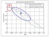
도 1은 종래기술에서 도플러 주파수에 따른 속도 추정 오류를 나타내는 그래프이다.1 is a graph showing a speed estimation error according to the Doppler frequency in the prior art.
상기 도 1을 참조하면, 가로축은 일반화된 도플러 주파수(fdTs)이고, 세로축은 평균 오차 값이다. fd는 최대 도플러 주파수이고, Ts는 샘플링 주기이다.Referring to FIG. 1, the horizontal axis represents a generalized Doppler frequency fd Ts and the vertical axis represents an average error value. fd is the maximum Doppler frequency and Ts is the sampling period.
실험환경은 레일리 페이딩(Rayleigh fading) 환경에서 신호대잡읍비(Signal to Noise Ratio: SNR)가 10dB와 20dB인 신호에 대하여 매 1000개의 샘플을 이용하여 추정한 결과에 대한 평균 오차 값이다.The experimental environment is the mean error value for the estimated result using every 1000 samples for signals with 10 dB and 20 dB Signal to Noise Ratio (SNR) in Rayleigh fading environment.
그래프 결과를 보면, SNR이 높은 20dB 환경에서 속도가 높은 영역인


실제로 2GHz 대역을 사용하는 이동통신시스템에서 1k의 심볼율(symbol rate)을 적용한 경우에 fdTs=0.05에 해당하는 이동 단말의 속도는 27km/h에 해당한다. 따라서 종래 기술을 적용한 경우에 SNR이 20dB 정도로 충분히 높다고 하여도
종래 기술에서, 저속도의 단말 속도 추정시 큰 오차를 보이는 현상은 크게 세 가지 원인으로 설명할 수 있다. 첫 번째 원인은 최대 도플러 주파수를 추정하기 위해 사용되는 베셀함수(Bessel function)의 역(inverse)이 저속도(
도 2는 종래 기술에 따른 베셀함수와 제곱 베셀함수(squared bessel function) 그래프를 도시하고 있다.2 illustrates a graph of a Bessel function and a squared Bessel function according to the prior art.
상기 도 1을 참조하면, 속도가 높은 'B' 영역


두 번째 원인은 부가잡음에 의한 오버 바이어스(over bias) 현상이 미치는 영향이 속도가 낮은 영역에서 더 두드러지게 나타나기 때문이다. 즉, 부가잡음은 이동 단말의 속도와 상관없이 샘플링 주기와 SNR에 의해 일정하게 나타나게 되므로, 낮은 속도 영역에서 측정값의 변화에 민감한 특징으로 부가잡음의 영향은 속도가 낮은 영역에서 상대적으로 커지게 된다.The second reason is that the effect of over bias caused by additional noise is more pronounced in the low speed region. That is, since the additional noise is constantly represented by the sampling period and the SNR irrespective of the speed of the mobile terminal, the effect of the additional noise becomes relatively large in the low speed region because it is sensitive to the change of the measured value in the low speed region. .
마지막으로, 만일 속도 추정시 SNR 값을 알고 있지 못할 경우, 잡음에 의해 측정값의 왜곡이 발생한다.Finally, if the SNR value is not known at the time of speed estimation, noise causes distortion of the measured value.
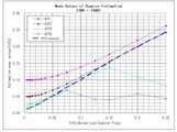
도 3은 종래기술에 다른 SNR이 10dB와 20dB인 경우에 추정 평균값을 나타내는 그래프이다.3 is a graph showing an estimated average value when the SNRs different from the prior art are 10 dB and 20 dB.
상기 도 3을 참조하면, 가로축은 일반화된 도플러 주파수(fdTs)이고, 세로축은 추정된 도플러 주파수이다. fd는 최대 도플러 주파수이고, Ts는 샘플링 주기이다. 결과를 보면 부가잡음이 있는 경우에 속도가 낮은 영역에서의 오버 바이어스 현상이 매우 심각하게 나타남을 알 수 있다.Referring to FIG. 3, the horizontal axis is a generalized Doppler frequency fd Ts and the vertical axis is an estimated Doppler frequency. fd is the maximum Doppler frequency and Ts is the sampling period. The results show that the over-biasing phenomenon in the low speed region is very serious when there is additional noise.
따라서, 이동통신시스템에서 저속도의 단말을 오차 없이 추정하기 위한 장치 및 방법이 필요하다.Accordingly, there is a need for an apparatus and method for estimating a low speed terminal without error in a mobile communication system.
본 발명의 목적은 이동통신시스템에서 속도추정 장치 및 방법을 제공함에 있다.An object of the present invention is to provide a speed estimation apparatus and method in a mobile communication system.
본 발명의 다른 목적은 이동통신시스템에서 저속도의 단말을 정확하게 추정하기 위한 장치 및 방법을 제공함에 있다.Another object of the present invention is to provide an apparatus and method for accurately estimating a low speed terminal in a mobile communication system.
상기한 목적들을 달성하기 위한 본 발명의 제 1 견지에 따르면, 이동통신시스템에서 속도추정 방법에 있어서, 다수의 서로 다른 샘플간격을 적용하여 수신신호를 지연시키는 과정과, 상기 다수의 서로 다른 샘플간격만큼 지연된 수신신호에 대해 각각 후보 최대 도플러 주파수를 추정하는 과정과, 상기 다수의 후보 최대 도플러 주파수 중에서 신뢰할 수 있는 구간에 있는 최대 도플러 주파수를 선택하는 과정을 포함하는 것을 특징으로 한다.According to a first aspect of the present invention for achieving the above object, a method for estimating a speed in a mobile communication system, the process of delaying a received signal by applying a plurality of different sample intervals, and the plurality of different sample intervals Estimating a candidate maximum Doppler frequency for each delayed received signal, and selecting a maximum Doppler frequency in a reliable interval among the plurality of candidate maximum Doppler frequencies.
상기한 목적들을 달성하기 위한 본 발명의 제 2 견지에 따르면, 이동통신시스템에서 속도추정 장치에 있어서, 다수의 서로 다른 샘플간격을 적용하여 수신신호를 지연시키는 다수의 지연기와, 상기 다수의 서로 다른 샘플간격만큼 지연된 수신신호에 대해 각각 후보 최대 도플러 주파수를 추정하는 추정기와, 상기 다수의 후보 최대 도플러 주파수 중에서 신뢰할 수 있는 구간에 있는 최대 도플러 주파수를 선택하는 선택기를 포함하는 것을 특징으로 한다.According to a second aspect of the present invention for achieving the above object, in the speed estimation apparatus in a mobile communication system, a plurality of delayers for delaying a received signal by applying a plurality of different sample intervals, and the plurality of different And an estimator for estimating a candidate maximum Doppler frequency for each received signal delayed by a sample interval, and a selector for selecting a maximum Doppler frequency in a reliable interval among the plurality of candidate maximum Doppler frequencies.
상술한 바와 같이, 이동통신시스템에서 높은 속도에 대해 낮은 샘플링 지연을 적용하고 낮은 속도에 대해 높은 샘플링 지연을 적용함으로써, 저속 이동국의 속도추정 및 부가잡음에 대하여 우수한 성능을 보인다.As described above, by applying a low sampling delay for a high speed and a high sampling delay for a low speed in a mobile communication system, it shows excellent performance against speed estimation and added noise of a low speed mobile station.
이하 본 발명의 바람직한 실시 예를 첨부된 도면의 참조와 함께 상세히 설명한다. 그리고, 본 발명을 설명함에 있어서, 관련된 공지기능 혹은 구성에 대한 구체적인 설명이 본 발명의 요지를 불필요하게 흐릴 수 있다고 판단된 경우 그 상세한 설명은 생략할 것이다. 그리고 후술되는 용어들은 본 발명에서의 기능을 고려하여 정의된 용어들로서 이는 사용자, 운용자의 의도 또는 관례 등에 따라 달라질 수 있다. 그러므로 그 정의는 본 명세서 전반에 걸친 내용을 토대로 내려져야 할 것이다.DETAILED DESCRIPTION OF THE PREFERRED EMBODIMENTS Reference will now be made in detail to the preferred embodiments of the present invention, examples of which are illustrated in the accompanying drawings. In the following description of the present invention, a detailed description of known functions and configurations incorporated herein will be omitted when it may make the subject matter of the present invention rather unclear. The following terms are defined in consideration of the functions of the present invention, and may be changed according to the intentions or customs of the user, the operator, and the like. Therefore, the definition should be based on the contents throughout this specification.
이하, 본 발명은 이동통신시스템에서 저속으로 이동하는 단말의 속도추정시 오차를 줄이기 위한 장치 및 방법에 대해 설명하기로 한다.Hereinafter, the present invention will be described an apparatus and method for reducing errors in the speed estimation of the terminal moving at a low speed in the mobile communication system.
본 발명은 자기상관(auto-correlation) 또는 공분산(covariance)을 이용하여 속도를 추정하는 경우에, 복수의 서로 다른 샘플 간격을 적용하여 최적의 단말 속도를 추정하는 방법이다.The present invention is a method of estimating an optimal terminal speed by applying a plurality of different sample intervals when estimating speed using auto-correlation or covariance.
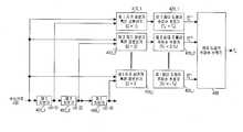
도 4는 본 발명의 실시 예에 따른 이동통신시스템에서 저속으로 이동하는 단말의 속도를 오차 없이 추정하기 위한 장치를 도시하고 있다.4 illustrates an apparatus for estimating the speed of a terminal moving at a low speed without error in a mobile communication system according to an exemplary embodiment of the present invention.
상기 도 4를 참조하면, 속도추정 장치는 제 1 내지 제 l 지연기(400_1 내지 400_l), 제 1 내지 제 l 자기상관기 혹은 공분산기(410_1 내지 410_l), 및 최대 도플러 주파수 선택기(430)를 포함하여 구성된다.Referring to FIG. 4, the speed estimating apparatus includes first to first delayers 400_1 to 400_l, first to first autocorrelators or covariators 410_1 to 410_l, and a maximum
상기 제 1 내지 제 l 지연기(400_1 내지 400_l)는 각각 해당 지연 샘플에 따라 수신신호를 지연시켜, 해당 제 1 내지 제 l 자기상관기 혹은 공분산기(410_1 내지 410_l)로 출력한다.The first to first delayers 400_1 to 400_l respectively delay the received signals according to the corresponding delay samples, and output the delayed signals to the corresponding first to first autocorrelators or covariators 410_1 to 410_l.
예를 들어, 상기 제 l 지연기(400_1)는 수신신호를 1개 샘플간격만큼 지연시켜 제 1 자기상관기 혹은 공분산기(410_1) 및 상기 제 2 지연기(400_2)로 출력한다. 그리고, 상기 제 2 지연기(400_2)는 상기 제 l 지연기(400_1)로부터의 출력신호를 1개 샘플간격만큼 지연시켜, 상기 제 3 자기상관기 혹은 공분산기(410_3) 및 상기 제 3 지연기(400_3)로 출력한다. 결국 상기 제 2 지연기(400_2)는 수신신호에 대해 2개 샘플간격만큼 지연된 신호를 상기 제 3 자기상관기 혹은 공분산기(410_3) 및 상기 제 3 지연기(400_3)로 출력한다. 구현에 따라, 상기 제 1 내지 제 l 지연기(400_1 내지 400_l)는 각각 해당 지연 값(1개 샘플, 2개 샘플,..., l개 샘플) 값을 적용하여, 수신신호를 지연시킬 수 있다.For example, the first delayer 400_1 delays the received signal by one sample interval and outputs the received signal to the first autocorrelator or covariator 410_1 and the second delayer 400_2. The second delay unit 400_2 delays the output signal from the first delay unit 400_1 by one sample interval, so that the third autocorrelator or covariator 410_3 and the third delay unit ( 400_3). As a result, the second delay unit 400_2 outputs a signal delayed by two sample intervals to the third autocorrelator or covariator 410_3 and the third delay unit 400_3. In some implementations, the first to lth delays 400_1 to 400_l may respectively apply corresponding delay values (1 sample, 2 samples, ..., l samples) to delay the received signal. have.
상기 제 1 내지 제 l 자기상관기 혹은 공분산기(410_1 내지 410_l)는 수신신호(C(i))와 해당 지연 샘플에 의해 지연된 수신신호(C(i-l)) 사이의 자기상 관(auto-correlation)과 공분산(covariance) 특성을 이용하여, 각각 최대 도플러 주파수를 산출한다.The first to l autocorrelators or covariators 410_1 to 410_l are auto-correlation between the received signal C (i) and the received signal C (il) delayed by the corresponding delay sample. Using the and covariance characteristics, the maximum Doppler frequencies are calculated, respectively.
여기서, 수신신호에 대한 자기상관 혹은 공분산을 측정시, 상기 측정 신호를


여기서,


여기서,

상기 <수학식1>과 상기 <수학식2>에서 최대 도플러 주파수에 대해 잡음에 의한 영향이 동일한 것은 샘플 간격이 커진 만큼 잡음(noise)의 대역폭이 줄기 때문이다.In
상기 <수학식1>과 상기 <수학식2>에서 보인 바와 같이, 지연이 커진 샘플을 이용한 최대 도플러 주파수 추정은 아래와 같은 몇 가지의 특징을 갖게 된다.As shown in
첫째, 낮은 속도에 해당하는 최대 도플러 주파수 추정 시, 베셀함수의 역을 적용함에 있어서, 상기 도 1에서 측정값 변화에 민감한 'A' 영역에서 측정값의 변화에 덜 민감한 'B' 영역의 특성이 적용된다. 따라서 저속의 이동 단말에 대한 속도 추정 값의 민감도가 중속 이상의 추정 값에 대한 민감도로 완화되는 특성을 보인다.First, in applying the inverse of the Bessel function in estimating the maximum Doppler frequency corresponding to a low speed, the characteristic of the 'B' region less sensitive to the change of the measured value in the 'A' region sensitive to the measured value change in FIG. Apply. Therefore, the sensitivity of the speed estimation value for the low speed mobile terminal is reduced to the sensitivity for the estimation value over the medium speed.
둘째, 낮은 속도에 해당하는 최대 도플러 주파수 추정 시, 페이딩(fading) 신호의 2차 특성으로 나타나는 자기상관이나 공분산의 변화가 잡음의 2차 특성으로 나타나는 자기상관이나 공분산의 특성과의 차이가 줄어들게 된다. 상기 <수학식1>과 상기 <수학식2>을 이용한 근사식 계산을 통하여 잡음과 레일레이 페이딩(Rayleigh fading) 신호의 자기상관 또는 공분산이 동일해지는 조건은 하기 <수학식 3>과 같이 유도된다.Second, when estimating the maximum Doppler frequency corresponding to a low speed, the change in autocorrelation or covariance represented by the secondary characteristics of the fading signal is reduced from the autocorrelation or covariance characteristic represented by the secondary characteristics of the noise. . The condition that the autocorrelation or covariance of the noise and Rayleigh fading signal are equal through the approximation

여기서, fd는 최대 도플러 주파수, Bm은 잡음 대역폭이다. 따라서, 샘플만큼 지연된 신호에 대해 잡음의 대역폭은
셋째, 지연된 샘플을 이용하는 경우, 관찰 가능한 최대 도플러 주파수가 줄어드는 현상이 발생한다. 이는 추정 시 사용되는 베셀함수의 역함수나 제곱 베셀함수의 역함수(squared inverse Bessel function)이 고유(unique) 영역이 줄어들게 되어 발생한다. 따라서 지연된 샘플을 이용한 측정의 신뢰성있는 범위는 지연이 커질수록 줄어드는 현상이 나타난다.Third, when using the delayed sample, the phenomenon that the maximum observable Doppler frequency decreases occurs. This occurs because the inverse of the Bessel function or the squared inverse Bessel function of the square Bessel function used in the estimation is reduced in the unique area. Therefore, the reliable range of measurements with delayed samples decreases as the delay increases.
상기 최대 도플러 주파수 선택기(430)는 상기 제 1 내지 제 l 자기상관기 혹은 공분산기(410_1 내지 410_l)로부터의 최대 도플러 주파수 값들 중, 가장 신뢰할 수 있는 구간에 있는 후보 최대 도플러 주파수를 선택하여, 이에 해당하는 단말의 속도를 추정한다. 즉, 상기 최대 도플러 주파수 선택기(430)는 높은 속도 영역에서는 지연이 적은 샘플을 적용한 결과를 이용하고, 낮은 속도 영역에서는 지연이 많은 샘플을 적용한 결과를 이용하여, 최대 도플러 주파수를 선택하게 된다.The maximum
도 5는 본 발명의 실시 예에 따른 이동통신시스템에서 저속으로 이동하는 단말의 속도를 오차 없이 추정하기 위한 흐름도를 도시하고 있다.5 is a flowchart illustrating an error-free estimation of a speed of a terminal moving at a low speed in a mobile communication system according to an exemplary embodiment of the present invention.
상기 도 5를 참조하면, 속도추정 장치는 500 단계에서 i=1로 설정한다. i값은 복수의 후보 최대 도플러 주파수를 선택하기 위한 파라미터다.Referring to FIG. 5, the speed estimating apparatus sets i = 1 in
이후, 상기 속도추정 장치는 502 단계에서 i값이 M 값보다 작거나 같은지를 비교한다. 상기 M은 최대 도플러 주파수 선택기(430)로부터 출력되는 총 후보 최대 도플러 주파수 개수이다.In
만약, i값이 M 값보다 작거나 같은 경우, 상기 속도추정 장치는 504 단계진행하여, i에 해당하는 지연 샘플(li) 값과 i에 해당하는 임계치(Thi)를 선택한다.If the i value is less than or equal to the M value, the speed estimating apparatus proceeds to step 504 to select a delay sample li value corresponding to i and a threshold value Thi corresponding toi .
이후, 상기 속도추정 장치는 506 단계에서 지연 샘플(li)을 적용한 자기상관 혹은 공분산에 의한 최대 도플러 주파수(

만약, 상기 속도추정 장치는 506 단계에서 지연 샘플(li)을 적용한 자기상관 혹은 공분산에 의한 최대 도플러 주파수(
만약, 502 단계에서 i값이 M 값보다 큰 경우, 상기 속도추정 장치는 510 단계로 진행하여, 최대 도플러 주파수를
이후, 본 발명의 절차를 종료한다.Thereafter, the procedure of the present invention is terminated.
상술한 바와 같이, 상기 도 5에서 M개의 후보 최대 도플러 주파수는 각각

또한, 상기 도 5에서 M-1개의 임계치(Th1, Th2,..., ThM-1)는 각각 해당 지연을 가지고 측정된 최대 도플러 주파수가 신뢰할 수 있는 구간의 최소 값이며,
도 6 내지 도 9는 본 발명에 따는 자기상관을 이용한 속도 추정 실험결과 그래프를 도시하고 있다.6 to 9 show graphs of results of velocity estimation experiments using autocorrelation according to the present invention.
상기 도 6과 상기 도 7에서 실험결과는 SNR 20dB의 환경에서 4개의 후보 최대 도플러 주파수 개수(M)를 이용한 결과 그래프이다. 이때 사용된 4개의 후보 최 대 도플러 주파수는 각각 1,2,4,8 샘플만큼 지연시키고
상기 도 6과 상기 도 7에서 'ACF', 'ACF2', 'ACF4', 'ACF8'는 각각 샘플 1, 2, 4, 8에 대한 지연에 대한 실험 결과이며, 'proposed'는 본 발명을 적용한 실험 결과이다.In FIGS. 6 and 7, 'ACF', 'ACF2', 'ACF4', and 'ACF8' are experimental results of delays for
상기 도 6은 일반화된 평균오차(normilized MSE)를 비교한 결과와 같이, 본 발명의 방법을 적용한 경우에는 종래 기술을 적용한 방법('ACF')이 가지는 저속에 대한 추정 오차가 크게 개선되어 있음을 확인할 수 있다.FIG. 6 shows that the estimation error for the low speed of the conventional method (ACF) is greatly improved when the method of the present invention is applied, as a result of comparing the normalized MSE. You can check it.
상기 도 7은 추정치의 평균값을 비교한 결과와 같이, 본 발명의 방법을 적용한 경우에는 종래 기술을 적용한 방법('ACF')이 가지는 오버 바이어스가 현저하게 감소함을 확인할 수 있다.As shown in FIG. 7, the overbias of the conventional method (ACF) is remarkably reduced when the method of the present invention is applied.
상기 도 8과 상기 도 9는 SNR 10dB의 환경에서의 실험 결과를 나타내었다. 상기 도 8과 상기 도 9의 실험환경은 임계치 설정을 제외하고 상기 도 6과 상기 도 7에서의 실험환경과 동일하다. SNR 10dB의 실험에서 사용된 임계치는 각각 Th1=0.27, Th2=0.13, Th3=0.061이다.8 and 9 show the experimental results in an environment of SNR 10dB. The experimental environment of FIGS. 8 and 9 is the same as the experimental environment of FIGS. 6 and 7 except for setting a threshold. The thresholds used in the SNR 10dB experiments were Th1 = 0.27, Th2 = 0.13, and Th3 = 0.061, respectively.
상기 도 6과 상기 도 7의 결과를 상기 도 8과 상기 도 9의 결과와 비교해 보면, 본 발명에 의한 성능 개선량이 잡음이 증가함에 따라 같이 증가함을 확인할 수 있다.Comparing the results of FIG. 6 and FIG. 7 with the results of FIGS. 8 and 9, it can be seen that the amount of performance improvement according to the present invention increases as the noise increases.
도 10 내지 도 13는 본 발명에 따는 공분산을 이용한 속도 추정 실험결과 그래프를 도시하고 있다.10 to 13 show graphs of results of velocity estimation experiments using covariance according to the present invention.
상기 도 10과 상기 도 11의 실험결과는 SNR 20dB의 환경에서 4개의 최대 도플러 주파수 개수(M=4)를 이용한 결과이다. 후보 최대 도플러 주파수에 적용된 지연 샘플은 상기 도 6 내지 상기 도 8과 동일하다
상기 도 10과 상기 도 11은 일반화된 평균 오차와 평균값을 비교한 그래프로써, 본 발명의 방법을 적용한 경우에는 종래 기술을 적용한 방법('COV')이 가지는 저속에 대한 추정 오차와 오버 바이어스 현상이 크게 개선되어 있음을 확인할 수 있다.10 and 11 are graphs comparing the averaged average value and the averaged value. When the method of the present invention is applied, the estimation error and the over bias phenomenon of the low speed of the conventional method ('COV') are It can be seen that it is greatly improved.
상기 도 12과 상기 도 13에서는 SNR 10dB의 환경에서의 실험 결과를 나타내었다. 상기 도 12과 상기 도 13의 실험환경은 임계치 설정을 제외하고 상기 도 10과 상기 도 11에서의 실험환경과 동일하다. SNR 10dB의 실험에서 사용된 임계치는 각각 Th1=0.18, Th2=0.085, Th3=0.04이다. 상기 도 10과 상기 도 11의 결과를 상기 도 12와 도 13의 결과와 비교해 보면, 본 발명에 의한 성능 개선량이 잡음이 증가함에 따라 같이 증가함을 확인할 수 있다.12 and 13 illustrate experimental results in an environment of SNR 10 dB. The experimental environment of FIGS. 12 and 13 is the same as the experimental environment of FIGS. 10 and 11 except for setting a threshold. The thresholds used in the experiments with SNR 10 dB are Th1 = 0.18, Th2 = 0.085 and Th3 = 0.04, respectively. Comparing the results of FIGS. 10 and 11 with the results of FIGS. 12 and 13, it can be seen that the amount of performance improvement according to the present invention increases as the noise increases.
한편 본 발명의 상세한 설명에서는 구체적인 실시 예에 관해 설명하였으나, 본 발명의 범위에서 벗어나지 않는 한도 내에서 여러 가지 변형이 가능함은 물론이다. 그러므로 본 발명의 범위는 설명된 실시 예에 국한되어 정해져서는 아니 되며 후술하는 특허청구의 범위뿐만 아니라 이 특허청구의 범위와 균등한 것들에 의해 정해져야 한다.While the present invention has been described in connection with what is presently considered to be the most practical and preferred embodiment, it is to be understood that the invention is not limited to the disclosed embodiments, but is capable of various modifications within the scope of the invention. Therefore, the scope of the present invention should not be limited to the described embodiments, but should be determined not only by the scope of the following claims, but also by the equivalents of the claims.
도 1은 종래기술에서 도플러 주파수에 따른 속도 추정 오류를 나타내는 그래프,1 is a graph showing a speed estimation error according to the Doppler frequency in the prior art,
도 2는 종래 기술에 따른 베셀함수와 제곱 베셀함수(squared bessel function) 그래프,2 is a graph of a Bessel function and a squared Bessel function according to the prior art,
도 3은 종래기술에 다른 SNR이 10dB와 20dB인 경우에 추정 평균값을 나타내는 그래프,3 is a graph showing an estimated average value when SNRs different from the prior art are 10 dB and 20 dB;
도 4는 본 발명의 실시 예에 따른 이동통신시스템에서 저속으로 이동하는 단말의 속도를 오차 없이 추정하기 위한 장치도,4 is an apparatus for estimating without error the speed of a terminal moving at a low speed in a mobile communication system according to an embodiment of the present invention;
도 5는 본 발명의 실시 예에 따른 이동통신시스템에서 저속으로 이동하는 단말의 속도를 오차 없이 추정하기 위한 흐름도,5 is a flowchart for estimating without error the speed of a terminal moving at a low speed in a mobile communication system according to an embodiment of the present invention;
도 6은 본 발명에 따른 자기상관을 이용한 속도 추정 실험결과 그래프,6 is a graph of a speed estimation experiment using autocorrelation according to the present invention;
도 7은 본 발명에 따른 자기상관을 이용한 속도 추정 실험결과 그래프,7 is a graph of a speed estimation experiment using autocorrelation according to the present invention;
도 8은 본 발명에 따는 자기상관을 이용한 속도 추정 실험결과 그래프,8 is a graph of a speed estimation experiment using autocorrelation according to the present invention;
도 9는 본 발명에 따는 자기상관을 이용한 속도 추정 실험결과 그래프,9 is a graph of a speed estimation experiment using autocorrelation according to the present invention;
도 10은 본 발명에 따른 자기상관을 이용한 속도 추정 실험결과 그래프,10 is a graph showing the results of speed estimation using autocorrelation according to the present invention;
도 11은 본 발명에 따른 자기상관을 이용한 속도 추정 실험결과 그래프,11 is a graph of a speed estimation experiment using autocorrelation according to the present invention;
도 12는 본 발명에 따는 자기상관을 이용한 속도 추정 실험결과 그래프 및,12 is a graph of a speed estimation experiment using autocorrelation according to the present invention;
도 13은 본 발명에 따는 자기상관을 이용한 속도 추정 실험결과 그래프.Figure 13 is a graph of the results of velocity estimation experiment using autocorrelation according to the present invention.
Claims (16)
Translated fromKorean


Priority Applications (2)
| Application Number | Priority Date | Filing Date | Title |
|---|---|---|---|
| KR1020090016164AKR101301240B1 (en) | 2009-02-26 | 2009-02-26 | Apparatus and method for velocity estimation in mobile communication system |
| US12/660,463US8290495B2 (en) | 2009-02-26 | 2010-02-26 | Apparatus and method for velocity estimation in mobile communication system |
Applications Claiming Priority (1)
| Application Number | Priority Date | Filing Date | Title |
|---|---|---|---|
| KR1020090016164AKR101301240B1 (en) | 2009-02-26 | 2009-02-26 | Apparatus and method for velocity estimation in mobile communication system |
Publications (2)
| Publication Number | Publication Date |
|---|---|
| KR20100097291A KR20100097291A (en) | 2010-09-03 |
| KR101301240B1true KR101301240B1 (en) | 2013-08-28 |
Family
ID=42631401
Family Applications (1)
| Application Number | Title | Priority Date | Filing Date |
|---|---|---|---|
| KR1020090016164AActiveKR101301240B1 (en) | 2009-02-26 | 2009-02-26 | Apparatus and method for velocity estimation in mobile communication system |
Country Status (2)
| Country | Link |
|---|---|
| US (1) | US8290495B2 (en) |
| KR (1) | KR101301240B1 (en) |
Families Citing this family (9)
| Publication number | Priority date | Publication date | Assignee | Title |
|---|---|---|---|---|
| US9297887B2 (en)* | 2012-02-29 | 2016-03-29 | Panasonic Corporation | Device for detecting intruding objects, and method for detecting intruding objects |
| CN104853367B (en)* | 2014-02-13 | 2018-07-24 | 普天信息技术有限公司 | A kind of moving velocity of terminal method of estimation and device |
| CN106707268A (en)* | 2015-11-13 | 2017-05-24 | 中兴通讯股份有限公司 | Speed estimation method and device for user terminal in wireless communication system |
| CN105848198B (en)* | 2016-03-18 | 2019-07-02 | 京信通信系统(中国)有限公司 | A method and device for determining terminal speed |
| US10187752B2 (en) | 2017-05-16 | 2019-01-22 | Apple Inc. | UE motion estimate based on cellular parameters |
| JP6926775B2 (en)* | 2017-07-24 | 2021-08-25 | 日本電気株式会社 | Moving target detection system and moving target detection method |
| US10075817B1 (en) | 2017-08-04 | 2018-09-11 | Apple Inc. | UE motion estimate in unconventional cell deployments |
| WO2019104542A1 (en)* | 2017-11-29 | 2019-06-06 | 北京小米移动软件有限公司 | Method and device for controlling mobile terminal to use network, base station, and user equipment |
| US11516051B2 (en)* | 2018-03-06 | 2022-11-29 | Samsung Electronics Co., Ltd. | Method and apparatus for AI-based UE speed estimation using uplink SRS measurements |
Citations (4)
| Publication number | Priority date | Publication date | Assignee | Title |
|---|---|---|---|---|
| US6542745B1 (en) | 1999-02-08 | 2003-04-01 | Mitsubishi Denki Kabushiki Kaisha | Method of estimating the speed of relative movement of a transmitter and a receiver, in communication with one another, of a telecommunication system |
| KR20050116010A (en)* | 2004-06-04 | 2005-12-08 | 삼성전자주식회사 | Velocity estimator in mobile communication system |
| US6987971B2 (en) | 2001-09-03 | 2006-01-17 | Stmicroelectronics N.V. | Process and device for estimating the speed of movement of a mobile terminal, in particular a cellular mobile telephone |
| KR20080023267A (en)* | 2005-07-04 | 2008-03-12 | 노키아 코포레이션 | Speed detection method in communication systems, receivers, network elements and processors |
Family Cites Families (12)
| Publication number | Priority date | Publication date | Assignee | Title |
|---|---|---|---|---|
| US6385460B1 (en)* | 1998-05-26 | 2002-05-07 | Conexant Systems, Inc. | Power management system for a mobile unit by reduced neighbor cell scanning |
| FI118877B (en)* | 2000-06-19 | 2008-04-15 | Valtion Teknillinen | Estimation of movement |
| US6862457B1 (en)* | 2000-06-21 | 2005-03-01 | Qualcomm Incorporated | Method and apparatus for adaptive reverse link power control using mobility profiles |
| KR100830495B1 (en)* | 2001-12-29 | 2008-05-21 | 엘지전자 주식회사 | Doppler transition estimation method and data transmission method using the same |
| US7369876B2 (en)* | 2003-03-04 | 2008-05-06 | Samsung Electronics Co., Ltd. | Apparatus and method for estimating a velocity of a mobile station in a mobile communication system |
| KR101009827B1 (en)* | 2003-09-16 | 2011-01-19 | 삼성전자주식회사 | Speed estimation device and method of mobile terminal in mobile communication system |
| KR101002857B1 (en)* | 2003-09-16 | 2010-12-21 | 삼성전자주식회사 | Method and device for estimating speed of mobile terminal in mobile communication system |
| KR100681260B1 (en)* | 2004-10-07 | 2007-02-09 | 삼성전자주식회사 | Speed Matched Channel Estimation Method Using Power Spectrum Based Speed Estimation and Demodulator of Mobile Communication Terminal Using the Same |
| US7541976B2 (en)* | 2005-01-20 | 2009-06-02 | New Jersey Institute Of Technology | System and/or method for estimating speed of a transmitting object |
| US7529319B2 (en)* | 2006-04-13 | 2009-05-05 | Mediatek Inc. | Speed estimation method for telecommunication system |
| US7647049B2 (en)* | 2006-07-12 | 2010-01-12 | Telefonaktiebolaget L M Ericsson (Publ) | Detection of high velocity movement in a telecommunication system |
| KR100929089B1 (en)* | 2006-11-28 | 2009-11-30 | 삼성전자주식회사 | Method and apparatus for estimating speed of mobile terminal using channel quality indicator information in mobile communication system |
- 2009
- 2009-02-26KRKR1020090016164Apatent/KR101301240B1/enactiveActive
- 2010
- 2010-02-26USUS12/660,463patent/US8290495B2/enactiveActive
Patent Citations (4)
| Publication number | Priority date | Publication date | Assignee | Title |
|---|---|---|---|---|
| US6542745B1 (en) | 1999-02-08 | 2003-04-01 | Mitsubishi Denki Kabushiki Kaisha | Method of estimating the speed of relative movement of a transmitter and a receiver, in communication with one another, of a telecommunication system |
| US6987971B2 (en) | 2001-09-03 | 2006-01-17 | Stmicroelectronics N.V. | Process and device for estimating the speed of movement of a mobile terminal, in particular a cellular mobile telephone |
| KR20050116010A (en)* | 2004-06-04 | 2005-12-08 | 삼성전자주식회사 | Velocity estimator in mobile communication system |
| KR20080023267A (en)* | 2005-07-04 | 2008-03-12 | 노키아 코포레이션 | Speed detection method in communication systems, receivers, network elements and processors |
Also Published As
| Publication number | Publication date |
|---|---|
| US8290495B2 (en) | 2012-10-16 |
| KR20100097291A (en) | 2010-09-03 |
| US20100216406A1 (en) | 2010-08-26 |
Similar Documents
| Publication | Publication Date | Title |
|---|---|---|
| KR101301240B1 (en) | Apparatus and method for velocity estimation in mobile communication system | |
| EP1480355B1 (en) | Velocity estimation apparatus and method using level crossing rate | |
| Kawabata et al. | Estimating velocity using diversity reception | |
| US8537759B2 (en) | Position adjusted guard time interval for OFDM-communications system | |
| RU2138909C1 (en) | Method and device for assessing channel quality in receiver | |
| KR102416604B1 (en) | Mehtod and device for precise positioning for wireless communication system | |
| US20070014254A1 (en) | Method and apparatus for measuring uplink data throughput in WiBro repeater | |
| KR102029930B1 (en) | Method and Apparatus for signal detection in Backscatter system | |
| US20080056220A1 (en) | System and method for determining a carrier to interference noise ratio | |
| JP5360205B2 (en) | Apparatus and method for evaluating Doppler spread in a mobile communication terminal | |
| CN1902873B (en) | Locating interfering devices in wireless networks using channel adaptation metrics | |
| KR101009827B1 (en) | Speed estimation device and method of mobile terminal in mobile communication system | |
| CN111786917A (en) | Channel estimation method, receiver and storage medium | |
| KR100725772B1 (en) | Method and apparatus for determining data rate | |
| US20050267370A1 (en) | Velocity estimation apparatus and method | |
| KR20060028131A (en) | Apparatus and method for delay spread estimation of multipath fading channel in wireless communication system | |
| US20090016472A1 (en) | Method and apparatus for signal quality estimation | |
| EP1052820B1 (en) | Method and apparatus to determine the speed of mobile communications apparatus | |
| KR20120047694A (en) | Methods of position tracking of mobile terminal using observed time difference of arrival and mobile terminal using the same | |
| US8442165B2 (en) | Method and apparatus for estimating Doppler frequency in a mobile terminal | |
| JP6180496B2 (en) | Terminal speed estimation method | |
| EP2854312A1 (en) | Receiver for a cellular communications network | |
| JP6239671B2 (en) | Terminal speed estimation method using Doppler spectrum | |
| KR100605940B1 (en) | Estimating apparatus and method of mobile station speed in a mobile communication system | |
| Adnani et al. | Analysis of wideband measurement data to assess and predict system performance for IMT2000 systems |
Legal Events
| Date | Code | Title | Description |
|---|---|---|---|
| PA0109 | Patent application | St.27 status event code:A-0-1-A10-A12-nap-PA0109 | |
| PG1501 | Laying open of application | St.27 status event code:A-1-1-Q10-Q12-nap-PG1501 | |
| A201 | Request for examination | ||
| PA0201 | Request for examination | St.27 status event code:A-1-2-D10-D11-exm-PA0201 | |
| R18-X000 | Changes to party contact information recorded | St.27 status event code:A-3-3-R10-R18-oth-X000 | |
| D13-X000 | Search requested | St.27 status event code:A-1-2-D10-D13-srh-X000 | |
| D14-X000 | Search report completed | St.27 status event code:A-1-2-D10-D14-srh-X000 | |
| PE0902 | Notice of grounds for rejection | St.27 status event code:A-1-2-D10-D21-exm-PE0902 | |
| P11-X000 | Amendment of application requested | St.27 status event code:A-2-2-P10-P11-nap-X000 | |
| P13-X000 | Application amended | St.27 status event code:A-2-2-P10-P13-nap-X000 | |
| E701 | Decision to grant or registration of patent right | ||
| PE0701 | Decision of registration | St.27 status event code:A-1-2-D10-D22-exm-PE0701 | |
| GRNT | Written decision to grant | ||
| PR0701 | Registration of establishment | St.27 status event code:A-2-4-F10-F11-exm-PR0701 | |
| PR1002 | Payment of registration fee | St.27 status event code:A-2-2-U10-U11-oth-PR1002 Fee payment year number:1 | |
| PG1601 | Publication of registration | St.27 status event code:A-4-4-Q10-Q13-nap-PG1601 | |
| FPAY | Annual fee payment | Payment date:20160728 Year of fee payment:4 | |
| PR1001 | Payment of annual fee | St.27 status event code:A-4-4-U10-U11-oth-PR1001 Fee payment year number:4 | |
| PR1001 | Payment of annual fee | St.27 status event code:A-4-4-U10-U11-oth-PR1001 Fee payment year number:5 | |
| FPAY | Annual fee payment | Payment date:20180727 Year of fee payment:6 | |
| PR1001 | Payment of annual fee | St.27 status event code:A-4-4-U10-U11-oth-PR1001 Fee payment year number:6 | |
| FPAY | Annual fee payment | Payment date:20190730 Year of fee payment:7 | |
| PR1001 | Payment of annual fee | St.27 status event code:A-4-4-U10-U11-oth-PR1001 Fee payment year number:7 | |
| PR1001 | Payment of annual fee | St.27 status event code:A-4-4-U10-U11-oth-PR1001 Fee payment year number:8 | |
| PR1001 | Payment of annual fee | St.27 status event code:A-4-4-U10-U11-oth-PR1001 Fee payment year number:9 | |
| PR1001 | Payment of annual fee | St.27 status event code:A-4-4-U10-U11-oth-PR1001 Fee payment year number:10 | |
| L13-X000 | Limitation or reissue of ip right requested | St.27 status event code:A-2-3-L10-L13-lim-X000 | |
| PR1001 | Payment of annual fee | St.27 status event code:A-4-4-U10-U11-oth-PR1001 Fee payment year number:11 | |
| PR1001 | Payment of annual fee | St.27 status event code:A-4-4-U10-U11-oth-PR1001 Fee payment year number:12 | |
| PR1001 | Payment of annual fee | St.27 status event code:A-4-4-U10-U11-oth-PR1001 Fee payment year number:13 |