KR101299360B1 - Led driving circuit for regulating the drive currents of a plurality of led - Google Patents
Led driving circuit for regulating the drive currents of a plurality of ledDownload PDFInfo
- Publication number
- KR101299360B1 KR101299360B1KR1020120124297AKR20120124297AKR101299360B1KR 101299360 B1KR101299360 B1KR 101299360B1KR 1020120124297 AKR1020120124297 AKR 1020120124297AKR 20120124297 AKR20120124297 AKR 20120124297AKR 101299360 B1KR101299360 B1KR 101299360B1
- Authority
- KR
- South Korea
- Prior art keywords
- led
- unit
- power supply
- led lighting
- driving circuit
- Prior art date
- Legal status (The legal status is an assumption and is not a legal conclusion. Google has not performed a legal analysis and makes no representation as to the accuracy of the status listed.)
- Expired - Fee Related
Links
Images


Classifications
- Y—GENERAL TAGGING OF NEW TECHNOLOGICAL DEVELOPMENTS; GENERAL TAGGING OF CROSS-SECTIONAL TECHNOLOGIES SPANNING OVER SEVERAL SECTIONS OF THE IPC; TECHNICAL SUBJECTS COVERED BY FORMER USPC CROSS-REFERENCE ART COLLECTIONS [XRACs] AND DIGESTS
- Y02—TECHNOLOGIES OR APPLICATIONS FOR MITIGATION OR ADAPTATION AGAINST CLIMATE CHANGE
- Y02B—CLIMATE CHANGE MITIGATION TECHNOLOGIES RELATED TO BUILDINGS, e.g. HOUSING, HOUSE APPLIANCES OR RELATED END-USER APPLICATIONS
- Y02B20/00—Energy efficient lighting technologies, e.g. halogen lamps or gas discharge lamps
- Y02B20/30—Semiconductor lamps, e.g. solid state lamps [SSL] light emitting diodes [LED] or organic LED [OLED]
Landscapes
- Circuit Arrangement For Electric Light Sources In General (AREA)
Abstract
Translated fromKorean
Description
Translated fromKorean본 발명은 엘이디별 전류 공급 조절 기능을 갖는 엘이디 조명 구동회로에 관한 것으로서, 특히 교류 다이렉트 방식 LED 구동회로의 각 전류채널에 접지저항을 개별 설치하고 이러한 개별 접지저항에 걸리는 전압값을 임의로 설정하는 동시에 각 접지저항의 설정된 임계 전압값을 기준으로 이전 채널의 스위칭 소자를 오/오프 제어하는 방식을 통해 각 전류채널의 전류 구동 특성을 자유롭게 조절할 수 있는 엘이디별 전류 공급 조절 기능을 갖는 엘이디 조명 구동회로에 관한 것이다.The present invention relates to an LED lighting driving circuit having a current supply control function for each LED. In particular, the ground resistance is individually installed in each current channel of the AC direct type LED driving circuit, and the voltage value applied to the individual ground resistance is arbitrarily set. The LED lighting driving circuit has a current supply control function for each LED that can freely adjust the current driving characteristics of each current channel by controlling on / off of the switching element of the previous channel based on the set threshold voltage value of each ground resistance. It is about.
LED(Light Emitting Diode)는 전류 구동 소자로써, 정전류가 안정적으로 공급되어야 정상적으로 동작할 수 있다. 특히 고전력을 요구하는 LED는 구동 전류가 크기 때문에(보통 350㎃ 이상) LED 자체에서 많은 열이 발생되고, 따라서 휘도의 열화율이 저전력에서의 LED보다 크다. 이는 LED의 수명과 직접적으로 연결되며 조명 시장에서 매우 중요한 요소로 작용하게 된다.LED (Light Emitting Diode) is a current driving device, and can be operated normally if a constant current is supplied stably. In particular, LEDs requiring high power have a large driving current (typically, 350 mA or more), so that the LED itself generates a lot of heat, and therefore, the deterioration rate of brightness is larger than that of LEDs at low power. This is directly linked to the lifetime of the LED and is very important in the lighting market.
초기 LED 조명의 경우 통상 SMPS(Switched mode power supply)의 buck type으로 구현되었고, 최근에는 대용량의 무효분(reactive component) 수를 획기적으로 줄인 교류 다이렉트 방식의 LED 조명 구동 방식이 제안 및 실시되고 있다.Initially, LED lighting is implemented as a buck type of a switched mode power supply (SMPS), and recently, an AC direct driving method of LED lighting, which dramatically reduces the number of reactive components, has been proposed and implemented.
상기 교류 다이렉트 방식의 LED 조명 구동 방식은 교류 전원이 직접 LED의 열에 인가되고, 시간상으로 변화하는 교류 전원의 전압값에 적합한 개수의 LED가 선택된 후, 선택된 LED만이 점등되도록 전류원을 평행 배치하여 제어하는 방식이다. 이는 근본적으로 직렬 연결된 LED들의 중간 노드들과 접지 사이에 다수의 전류원을 배치하고, 이를 통해 입력 교류 전압의 크기에 맞게 켜지는 LED의 수를 능동적으로 조절하기 위한 것이다.In the AC direct driving method of LED lighting, AC power is directly applied to the heat of the LED, and a number of LEDs suitable for the voltage value of the AC power that changes in time is selected, and then the current source is arranged in parallel so that only the selected LED is turned on. That's the way. This is essentially by placing multiple current sources between the intermediate nodes of the LEDs in series and ground, thereby actively controlling the number of LEDs that are turned on to match the magnitude of the input AC voltage.
교류 다이렉트 방식의 LED 조명 구동회로를 개념적으로 설명하면, 교류 다이렉트 방식의 LED 조명 구동회로는 AC전원과 디머 및 정파정류기를 포함하는 전원부 그리고 동작 제어부와 다수의 LED 및 이러한 LED의 수에 대응되는 전류원을 포함하는 구동부로 구성되어 있다. 그리고 동작 제어부는 전원부에서 발생된 전파 정류된 교류 전압을 입력받고, 이렇게 입력되는 교류 전압이 사전 설정된 값에 도달되면 해당 전류원의 점등과 점멸을 제어한다.The AC direct LED lighting driving circuit is conceptually described. An AC direct LED lighting driving circuit includes an AC power supply, a power supply unit including a dimmer and a rectifier, an operation control unit, a plurality of LEDs, and a current source corresponding to the number of such LEDs. It is composed of a drive unit including a. The operation control unit receives the full-wave rectified AC voltage generated from the power supply unit, and controls the lighting and blinking of the corresponding current source when the input AC voltage reaches a preset value.
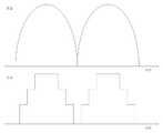
도 1은 종래 교류 다이렉트 방식 LED 구동회로의 일 예를 보인 도면이고, 도 2는 도 1에 따른 교류 다이렉트 방식 LED 구동회로의 전류 파형을 보인 도면이다.1 is a view showing an example of a conventional AC direct type LED driving circuit, Figure 2 is a view showing a current waveform of the AC direct type LED driving circuit according to FIG.
도 1의 교류 다이렉트 방식 LED 구동회로는 상술한 바와 같이 AC전원(11)과 디머(12) 및 정파정류기(13)를 포함하는 전원부(10) 그리고 다수의 LED(21~26)로 형성되는 LED 조명부(20) 및 LED 조명부(20)의 LED 출력단에 접속되는 전류원(30)을 포함하여 구성된다.As described above, the AC direct type LED driving circuit of FIG. 1 includes an
여기서 교류 다이렉트 방식 LED 구동회로는 V1 < V2 < V3의 조건이 만족될 경우, VAC 전압의 증가 시 OPA1, OPA2, OPA3의 순서로 동작하고 이와 반대로 VAC 전압의 감소 시 OPA3, OPA2, OPA1의 순서로 동작하게 되며, 이에 따라 전류 제어는 도 2의 형태가 된다.Here, AC direct type LED driving circuit operates in the order of OPA1, OPA2, OPA3 when the VAC voltage increases when the condition of V1 <V2 <V3 is satisfied, and OPA3, OPA2, OPA1 when the VAC voltage decreases. And thus the current control is in the form of FIG. 2.
즉, 도 2는 도 1에 따른 교류 다이렉트 방식 LED 구동회로의 구동 시 전압에 따른 전류 파형을 나타낸 것으로서, 이때 V3 > V2 > V1의 조건은 반드시 만족되어야 하므로 전류 파형은 중앙이 증가된 계단 형태의 파형이 된다.That is, FIG. 2 shows a current waveform according to voltage when the AC direct type LED driving circuit according to FIG. 1 is driven. In this case, since the condition of V3> V2> V1 must be satisfied, the current waveform has a stepped shape with an increased center. It becomes a waveform.
그러나 이는 교류 다이렉트 방식 LED 구동회로를 용도 등에 따라 다른 형태나 다른 크기의 전류값을 갖도록 설계 시 방해 요인이 된다. 다시 말해 교류 다이렉트 방식 LED 구동회로의 설계 시 상기 ‘V3 > V2 > V1’의 조건에 의해 제약을 받게 된다.However, this is an obstacle when designing an AC direct type LED driving circuit to have a current value of a different shape or size according to the use. In other words, when designing the AC direct type LED driving circuit, it is limited by the condition of 'V3> V2> V1'.
본 발명은 교류 다이렉트 방식 LED 구동회로의 각 전류채널에 접지저항을 개별 설치하고 이러한 개별 접지저항에 걸리는 전압값을 임의로 설정하는 동시에 각 접지저항의 설정된 임계 전압값을 기준으로 이전 채널의 스위칭 소자를 오/오프 제어하는 방식을 통해 각 전류채널의 전류 구동 특성을 자유롭게 조절할 수 있는 엘이디별 전류 공급 조절 기능을 갖는 엘이디 조명 구동회로를 제공하는데 목적이 있다.The present invention separately installs the grounding resistors in each current channel of the AC direct type LED driving circuit and arbitrarily sets the voltage value applied to the individual grounding resistors, while simultaneously switching the switching elements of the previous channel based on the set threshold voltage values of the respective grounding resistors. It is an object of the present invention to provide an LED lighting driving circuit having a current supply control function for each LED, which can freely adjust the current driving characteristics of each current channel through an on / off control method.
상기와 같은 목적을 달성하기 위해 본 발명에 따른 엘이디별 전류 공급 조절 기능을 갖는 엘이디 조명 구동회로는, 외부의 교류전원이 공급되는 전원공급부 및 상기 전원공급부를 통해 인가되는 교류전원의 정류회로를 포함하는 전원부와, 상기 전원부와의 접속점으로부터 최단 거리에 위치한 제1 LED를 시작으로 전원부에서 최장 거리에 위치한 제n LED를 포함하여 상기 제1 LED가 상기 전원부에 접속되는 동시에 각각의 LED가 직렬 연결되는 LED 조명부와, 상기 LED 조명부를 형성하는 각 LED의 출력단에 개별 접속되어 해당 LED에 대한 전류공급채널을 형성하며 접지저항을 개별적으로 구비하는 복수의 스위칭 회로부와, 상기 스위칭 회로부에 개별 접속되어 상기 접지저항에 걸리는 전압값이 사전 설정된 임계 전압값을 초과 시 상기 전원부에 상대적으로 근접된 이전 스위칭 회로부를 오프시키는 스위칭 회로 제어부를 포함하여 구성된다.In order to achieve the above object, an LED lighting driving circuit having a current supply control function for each LED according to the present invention includes a power supply unit to which external AC power is supplied and a rectifier circuit of AC power applied through the power supply unit. The first LED is connected to the power supply unit, including the power supply unit and the nth LED located at the longest distance from the power supply unit, including the first LED located at the shortest distance from the connection point with the power supply unit. A plurality of switching circuits individually connected to an LED lighting unit, an output terminal of each LED forming the LED lighting unit to form a current supply channel for the corresponding LEDs, and each of which has a grounding resistance; When the voltage value applied to the resistance exceeds a preset threshold voltage value, the power supply is relatively close to the power supply. A is configured to include a switching circuit control section for previously off the switching circuit portion.
또한, 상기 전원부는, 상기 전원공급부에 접속되어 교류전압을 인가받고 상기 정류회로에 출력전압을 인가하는 디머를 더 포함하는 것을 특징으로 한다.
또한, 상기 스위칭 회로부는 상기 LED 조명부의 LED 출력단에 접속되는 동시에 상기 접지저항에 접속되는 스위칭 소자 및 상기 LED 조명부의 LED에 대한 기준전압과 상기 접지저항에 걸리는 전압값을 비교하는 제1 비교기를 포함하며, 상기 스위칭 회로 제어부는 상기 스위칭 소자의 출력라인에 병렬 접속되어 상기 접지저항에 걸리는 전압값이 입력되고 입력된 접지저항의 전압값을 해당 접지저항의 사전 설정된 임계 전압값과 비교하는 제2 비교기 및 상기 제2 비교기의 출력단에 접속되는 반전버퍼 그리고 상기 제1 비교기의 출력단과 상기 스위칭 소자 간 접속라인에 직렬 연결되는 제1 스위치 및 상기 제1 스위치와 상기 스위칭 소자 간 접속라인에 병렬 연결되는 제2 스위치를 포함하여 상기 제1 스위치와 제2 스위치가 상기 제2 비교기 또는 반전버퍼의 출력신호에 의해 온/오프 되는 것을 특징으로 한다.The power supply unit may further include a dimmer connected to the power supply unit to receive an AC voltage and to apply an output voltage to the rectifier circuit.
The switching circuit unit may include a switching element connected to the LED output terminal of the LED lighting unit and a first comparator for comparing the reference voltage for the LED of the LED lighting unit with a voltage value applied to the ground resistance. The switching circuit controller is connected to an output line of the switching element in parallel to input a voltage value applied to the ground resistance, and compares the input voltage value of the ground resistance with a preset threshold voltage value of the ground resistance. And an inverting buffer connected to an output terminal of the second comparator, a first switch connected in series to a connection line between the output terminal of the first comparator and the switching element, and a second switch connected in parallel to the connection line between the first switch and the switching element. The first switch and the second switch including the second switch is the output of the second comparator or inverting buffer It is characterized in that the on / off by the output signal.
삭제delete
또한, 상기 스위칭 소자는 상기 LED 구동부의 LED 출력단에 드레인이 접속되고 상기 접지저항에 소스가 접속되며 상기 비교기에 게이트가 접속되는 전계효과 트랜지스터(MOS FET)인 것을 특징으로 한다.The switching element may be a field effect transistor (MOS FET) having a drain connected to an LED output terminal of the LED driver, a source connected to the ground resistor, and a gate connected to the comparator.
또한, 상기 스위칭 회로부는, 상기 LED 조명부의 모든 LED 출력단에 개별 접속되거나 또는 둘 이상의 LED가 직렬 연결되어 형성되는 LED 그룹별로 각 LED 그룹의 상기 전원부로부터 가장 먼 거리에 위치한 LED 출력단에 접속되는 것을 특징으로 한다.The switching circuit unit may be connected to all LED output terminals of the LED lighting unit individually or to an LED output terminal located farthest from the power supply unit of each LED group for each LED group formed by connecting two or more LEDs in series. It is done.
본 발명에 따르면, 교류 다이렉트 방식 LED 구동회로의 각 전류채널에 접지저항을 개별 설치하고 이러한 개별 접지저항에 걸리는 전압값을 임의로 설정하는 동시에 각 접지저항의 설정된 임계 전압값을 기준으로 이전 채널의 스위칭 소자를 오/오프 제어하는 방식을 통해 각 전류채널의 전류 구동 특성을 자유롭게 조절할 수 있다.According to the present invention, the ground resistance is individually installed in each current channel of the AC direct type LED driving circuit, and the voltage value applied to the individual ground resistance is arbitrarily set, while switching the previous channel based on the set threshold voltage value of each ground resistance. By controlling the device on and off, the current driving characteristics of each current channel can be freely adjusted.
도 1은 종래 교류 다이렉트 방식 LED 구동회로의 일 예를 보인 도면
도 2는 도 1에 따른 교류 다이렉트 방식 LED 구동회로의 전류 파형을 보인 도면
도 3은 본 발명의 일 실시예에 따른 엘이디별 전류 공급 조절 기능을 갖는 엘이디 조명 구동회로를 보인 도면
도 4는 도 3에 따른 엘이디별 전류 공급 조절 기능을 갖는 엘이디 조명 구동회로의 전류 파형을 보인 도면1 is a view showing an example of a conventional AC direct type LED driving circuit
2 is a view showing a current waveform of the AC direct type LED driving circuit according to FIG.
3 is a view showing the LED lighting driving circuit having a current supply control function for each LED according to an embodiment of the present invention
4 is a view showing the current waveform of the LED lighting driving circuit having the LED-specific current supply control function according to FIG.
이하에서는, 첨부된 도면을 참조하여 본 발명의 일 실시예에 따른 엘이디별 전류 공급 조절 기능을 갖는 엘이디 조명 구동회로를 상세하게 설명한다.Hereinafter, with reference to the accompanying drawings will be described in detail an LED lighting driving circuit having a current supply control function for each LED according to an embodiment of the present invention.
도 3은 본 발명의 일 실시예에 따른 엘이디별 전류 공급 조절 기능을 갖는 엘이디 조명 구동회로를 보인 도면이다.3 is a view showing an LED lighting driving circuit having a current supply control function for each LED according to an embodiment of the present invention.
도시된 바와 같이, 본 발명에 따른 엘이디별 전류 공급 조절 기능을 갖는 엘이디 조명 구동회로(100: 이하 “엘이디 조명 구동회로”라 함)는, 전원부(110), LED 조명부(120), 스위칭 회로부(130), 스위칭 회로 제어부(140)를 포함하여 구성된다.As shown, the LED lighting driving circuit 100 (hereinafter referred to as "LED lighting driving circuit") having the LED-specific current supply control function according to the present invention, the
전원부(110)는 전원공급부(111) 및 정류회로(112)를 포함하여 구성된다. 또한 전원부(110)는 디머(113)를 더 포함하여 구성될 수 있다. 전원공급부(111)는 외부의 교류전원(AC전원, 이하 ‘교류전원’이라 함)과 접속되어 해당 교류전원을 공급받으며, 정류회로(112)는 전원공급부(111)를 통해 인가되는 교류전원을 정류한다. 그리고 디머(113)는 전원공급부(111)와 정류회로(112) 간 접속라인에 직렬 접속되어 전원공급부(111)로부터 교류전압을 인가받은 후 정류회로(112)에 출력전압을 인가한다. 여기서 디머(113)는 통상의 디머 중 어느 한 종류가 선택되어 사용될 수 있으며, 따라서 본 실시예에서 이에 대한 구체적인 설명 및 도시는 생략한다.The
LED 조명부(120)는 복수의 LED(120-1~126)를 포함하여 형성되는 것으로서, 즉 전원부(110)와의 접속점으로부터 최단 거리에 위치한 제1 LED(121) 및 이러한 제1 LED(121)를 시작으로 전원부(110)로부터 최장 거리에 위치한 제6 LED(126)를 포함하여 구성된다. 여기서 본 실시예는 LED 조명부(120)가 제1 LED(121)부터 제6 LED(126)까지 6개의 LED가 포함되는 형태를 예로 하였으나, 본 발명이 이에 한정되는 것은 아니며, LED 구동부(120)는 둘 이상의 LED를 포함하는 조건을 만족하는 범위 내에서 다양한 수로 형성될 수 있다.The
그리고 제1 LED(121)는 전원부(110)에 전기적으로 접속되며, 이러한 제1 LED(121) 및 조명부(120)에 포함되는 모든 LED(121~126)는 서로 직렬 연결된다.The
스위칭 회로부(130)는 LED 조명부(120)를 형성하는 LED(121~126)의 출력단에 접속되며, 이러한 스위칭 회로부(130) 각각은 해당 LED(121~1206)에 대한 전류공급채널을 형성한다. 또한 스위칭 회로부(130) 각각은 접지저항(133)을 개별적으로 구비한다. 본 실시예에서는 두 개의 LED가 하나의 그룹을 형성하여 각 그룹의 전원부로부터 상대적으로 먼 LED의 출력단에 스위칭 회로부(130)가 접속되는 형태를 예로 하였으나, 본 발명이 이에 한정되는 것은 아니며, 스위칭 회로부(130)는 LED 조명부(120)의 모든 LED(121~126) 출력단에 개별 접속되거나 또는 셋 이상의 LED로 형성되는 그룹별로 각 그룹의 전원부로부터 상대적으로 먼 LED 출력단에 접속되는 형태 등 다양하게 변형 실시될 수 있다.The
그리고 이와 같은 스위칭 회로부(130)는 스위칭 소자(131)와 제1 비교기(132)를 포함하는 것으로서, 스위칭 소자(131)는 LED 구동부(120)의 LED 출력단에 접속되는 동시에 접지저항(133)에 접속되며, 제1 비교기(132)는 엘이디 조명 구동회로(100) 내의 기준전압과 접지저항(133)의 전압을 비교한다. 또한 스위칭 소자(131)는 제1 비교기(132)의 출력에 따라 LED 구동부(120)의 LED(121~126)에 접속되는 제1 전류경로 및 접지저항(133)에 접속되는 제2 전류경로 중 어느 한 쪽으로 스위칭 동작한다.The switching
본 실시예에서는 스위칭 소자(131)가 LED 조명부(120)의 LED 출력단에 드레인이 접속되고, 접지저항(133)에 소스가 접속되며, 제1 비교기(132)에 게이트가 접속되는 전계효과 트랜지스터(MOS FET)인 것을 예로 하였으나, 본 발명이 이에 한정되는 것은 아니다.In this embodiment, the switching
스위칭 회로 제어부(140)는 스위칭 회로부(130)에 개별 접속되어 접지저항(13)에 걸리는 전압값이 사전 설정된 임계 전압값을 초과 시 전원부(110)에 상대적으로 근접된 이전 스위칭 회로부(130)를 오프시킨다.The switching
도면을 참조하면, 제6 LED 출력단(126)의 스위칭 회로부(130)에 접속된 스위칭 회로 제어부(140)가 접지저항 R3에 걸리는 전압값이 사전 설정된 임계 전압값을 초과 시 제4 LED(124)의 출력단에 접속된 스위칭 회로부(130)를 오프시킨다. 또한 제4 LED(124) 출력단의 스위칭 회로부(130)에 접속된 스위칭 회로 제어부(140)가 접지저항 R2에 걸리는 전압값이 사전 설정된 임계 전압값을 초과 시 제2 LED(124)의 출력단에 접속된 스위칭 회로부(130)를 오프시킨다.Referring to the drawings, when the voltage value applied to the ground resistance R3 of the
이와 같은 스위칭 회로 제어부(140)는 제2 비교기(141), 반전버퍼(142), 제1 스위치(143), 제2 스위치(144)를 포함하여 구성된다.The
제2 비교기(141)는 스위칭 소자(131)의 출력라인에 병렬 접속되어 접지저항(133)에 걸리는 전압값이 입력되며, 이에 따라 제2 비교기(141)는 입력되는 접지저항(133)의 전압값을 해당 접지저항(133)의 사전 설정된 임계 전압값과 비교하여 그 비교 결과에 따라 제1 및 제2 스위치(143,144)를 오프(OFF) 시키는 제어신호를 출력한다.The
반전버퍼(142)는 제2 비교기(141)의 출력단에 접속되며, 이와 같은 반전버퍼(142)는 제2 비교기(141)의 출력 신호에 따라 제1 및 제2 스위치(143,144)를 온(ON) 시키는 제어신호를 출력한다.The inverting
제1 스위치(143)는 제1 비교기(132)의 출력단과 스위칭 소자(131) 간 접속라인에 직렬 연결된다.The
제 2 스위치(144)는 제1 스위치(143) 및 제1 스위치(143)와 스위칭 소자(131) 간 접속라인에 병렬 연결된다.The
이에 따라, 제1 스위치(143)와 제2 스위치(144)가 제2 비교기(141) 또는 반전버퍼(142)의 출력신호에 의해 온/오프된다.Accordingly, the
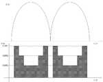
이와 같은 스위칭 회로 제어부(140)의 구성에 의해서, 각 전류채널의 전류 I1, I2, I3는 각각 V1/R1, V2/R2, V3/R3의 값을 가지게 되며, 결과적으로 기존 교류 다이렉트 방식 LED 구동회로에서 V3>V2>V1의 조건으로 인해 제약을 받는 것과는 전혀 상관없이 엘이디 조명 구동회로(100)의 각 전류채널의 전류 구동 특성을 자유롭게 조절할 수 있다. 그리고 이는 도 4를 통해서도 확인할 수 있다.By the configuration of the
도 4는 도 3에 따른 엘이디별 전류 공급 조절 기능을 갖는 엘이디 조명 구동회로의 전류 파형을 보인 도면으로서, 도 2에 따른 기존 교류 다이렉트 방식 LED 구동회로의 계단 형태 전류파형과 확연히 대비되도록 엘이디 조명 구동회로(100)의 전류채널에 의한 전류 구동 특성을 극단적인 형태로 설계한 예에 해당한다.Figure 4 is a view showing the current waveform of the LED lighting driving circuit having a current supply control function according to the LED according to Figure 3, LED lighting driving circuit so as to clearly contrast with the step-shaped current waveform of the conventional AC direct type LED driving circuit according to FIG. This corresponds to an example in which the current driving characteristic of the
상술한 도 3 및 4를 참조한 실시예의 설명에서 알 수 있는 바와 같이, 본 발명에 따른 엘이디별 전류 공급 조절 기능을 갖는 엘이디 조명 구동회로는, 교류 다이렉트 방식 LED 구동회로의 각 전류채널에 접지저항을 개별 설치하고 이러한 개별 접지저항에 걸리는 전압값을 임의로 설정하는 동시에 각 접지저항의 설정된 임계 전압값을 기준으로 이전 채널의 스위칭 소자를 오/오프 제어하는 방식을 통해 각 전류채널의 전류 구동 특성을 자유롭게 조절할 수 있도록 한다.As can be seen from the description of the embodiment with reference to FIGS. 3 and 4 described above, the LED lighting driving circuit having the LED-specific current supply control function according to the present invention, the ground resistance to each current channel of the AC direct type LED driving circuit It is possible to freely control the current driving characteristics of each current channel by individually installing and arbitrarily setting the voltage value applied to the individual ground resistors, and controlling the switching elements of the previous channel on / off based on the set threshold voltage value of each ground resistor. Make it adjustable.
이상에서 설명한 것은 본 발명에 따른 엘이디별 전류 공급 조절 기능을 갖는 엘이디 조명 구동회로를 실시하기 위한 하나의 실시예에 불과한 것으로서, 본 발명은 상기한 실시 예에 한정되지 않고, 이하의 특허청구범위에서 청구하는 바와 같이 본 발명의 요지를 벗어 남이 없이 당해 발명이 속하는 분야에서 통상의 지식을 가진 자라면 누구든지 다양한 변경 실시가 가능한 범위까지 본 발명의 기술적 정신이 있다고 할 것이다.What has been described above is only one embodiment for implementing the LED lighting driving circuit having the LED-specific current supply control function according to the present invention, the present invention is not limited to the above-described embodiment, in the following claims As claimed, any person having ordinary skill in the art without departing from the gist of the present invention will have the technical spirit of the present invention to the extent that various modifications can be made.
100 : 엘이디 구동회로 110 : 전원부
111 : 전원공급부 112 : 정류회로
113 : 디머 120 : LED 조명부
121~126 : LED 130 : 스위칭 회로부
131 : 스위칭 소자 132 : 제1 비교기
133 : 접지저항 140 : 스위칭 회로부
131 : 스위칭 소자 132 : 비교기
133 : 접지저항 140 : 스위칭 회로 제어부
141 : 제2 비교기 142 : 반전버퍼
143 : 제1 스위치 144 : 제2 스위치100: LED driving circuit 110: power supply
111: power supply unit 112: rectifier circuit
113: dimmer 120: LED lighting part
121 ~ 126: LED 130: switching circuit
131: switching element 132: first comparator
133: grounding resistance 140: switching circuit
131: switching element 132: comparator
133: ground resistance 140: switching circuit control
141: second comparator 142: inverting buffer
143: first switch 144: second switch
Claims (5)
Translated fromKorean상기 전원부와의 접속점으로부터 최단 거리에 위치한 제1 LED를 시작으로 전원부에서 최장 거리에 위치한 제n LED를 포함하여 상기 제1 LED가 상기 전원부에 접속되는 동시에 각각의 LED가 직렬 연결되는 LED 조명부;
상기 LED 조명부를 형성하는 LED의 출력단에 개별 접속되어 해당 LED에 대한 전류공급채널을 형성하며 접지저항을 개별적으로 구비하는 복수의 스위칭 회로부;
상기 스위칭 회로부에 개별 접속되어 상기 접지저항에 걸리는 전압값이 사전 설정된 임계 전압값을 초과 시 상기 전원부에 상대적으로 근접된 이전 스위칭 회로부를 오프시키는 스위칭 회로 제어부를 포함하는 엘이디별 전류 공급 조절 기능을 갖는 엘이디 조명 구동회로.A power supply unit including a power supply unit to which an external AC power is supplied and a rectification circuit of an AC power supply to be applied through the power supply unit;
An LED lighting unit including an n-th LED located at a longest distance from a power source, the first LED being located at a shortest distance from a connection point with the power source unit, the first LED being connected to the power source unit and each LED being connected in series;
A plurality of switching circuit units connected to an output terminal of the LED forming the LED lighting unit to form a current supply channel for the LED, and each having a ground resistance;
And a switching circuit control unit which is individually connected to the switching circuit unit and turns off the previous switching circuit unit relatively close to the power supply unit when the voltage value applied to the ground resistance exceeds a preset threshold voltage value. LED lighting driving circuit.
상기 전원부는, 상기 전원공급부에 접속되어 교류전압을 인가받고 상기 정류회로에 출력전압을 인가하는 디머를 더 포함하는 것을 특징으로 하는 엘이디별 전류 공급 조절 기능을 갖는 엘이디 조명 구동회로.The method of claim 1,
And the power supply unit further includes a dimmer connected to the power supply unit to receive an AC voltage and to apply an output voltage to the rectifier circuit.
상기 스위칭 회로부는 상기 LED 조명부의 LED 출력단에 접속되는 동시에 상기 접지저항에 접속되는 스위칭 소자 및 상기 LED 조명부의 LED에 대한 기준전압과 상기 접지저항에 걸리는 전압값을 비교하는 제1 비교기를 포함하며,
상기 스위칭 회로 제어부는 상기 스위칭 소자의 출력라인에 병렬 접속되어 상기 접지저항에 걸리는 전압값이 입력되고 입력된 접지저항의 전압값을 해당 접지저항의 사전 설정된 임계 전압값과 비교하는 제2 비교기 및 상기 제2 비교기의 출력단에 접속되는 반전버퍼 그리고 상기 제1 비교기의 출력단과 상기 스위칭 소자 간 접속라인에 직렬 연결되는 제1 스위치 및 상기 제1 스위치와 상기 스위칭 소자 간 접속라인에 병렬 연결되는 제2 스위치를 포함하여 상기 제1 스위치와 제2 스위치가 상기 제2 비교기 또는 반전버퍼의 출력신호에 의해 온/오프 되는 것을 특징으로 하는 엘이디별 전류 공급 조절 기능을 갖는 엘이디 조명 구동회로.3. The method according to claim 1 or 2,
The switching circuit unit includes a switching element connected to the LED output terminal of the LED lighting unit and connected to the ground resistance and a first comparator for comparing a reference voltage for the LED of the LED lighting unit with a voltage value applied to the ground resistance,
The switching circuit controller is connected to an output line of the switching element in parallel and a voltage value applied to the ground resistance is input, and a second comparator for comparing the voltage value of the input ground resistance with a predetermined threshold voltage value of the ground resistance; An inverting buffer connected to the output terminal of the second comparator and a first switch connected in series to the connection line between the output terminal of the first comparator and the switching element and a second switch connected in parallel to the connection line between the first switch and the switching element LED lighting driving circuit having a current supply control function for each LED, characterized in that the first switch and the second switch is turned on / off by the output signal of the second comparator or inverting buffer.
상기 스위칭 소자는 상기 LED 조명부의 LED 출력단에 드레인이 접속되고 상기 접지저항에 소스가 접속되며 상기 제1 비교기에 게이트가 접속되는 전계효과 트랜지스터(MOS FET)인 것을 특징으로 하는 엘이디별 전류 공급 조절 기능을 갖는 엘이디 조명 구동회로.The method of claim 3, wherein
The switching element is a field effect transistor (MOS FET) characterized in that the drain is connected to the LED output terminal of the LED lighting unit, the source is connected to the ground resistor, the gate is connected to the first comparator (MOS FET) LED lighting driving circuit having a.
상기 스위칭 회로부는, 상기 LED 조명부의 모든 LED 출력단에 개별 접속되거나 또는 둘 이상의 LED가 직렬 연결되어 형성되는 LED 그룹별로 각 LED 그룹의 상기 전원부로부터 가장 먼 거리에 위치한 LED 출력단에 접속되는 것을 특징으로 하는 엘이디별 전류 공급 조절 기능을 갖는 엘이디 조명 구동회로.3. The method according to claim 1 or 2,
The switching circuit unit may be connected to all LED output terminals of the LED lighting unit individually or to the LED output terminal located farthest from the power unit of each LED group for each LED group formed by two or more LEDs connected in series. LED lighting driving circuit having a current supply control function for each LED.
Priority Applications (1)
| Application Number | Priority Date | Filing Date | Title |
|---|---|---|---|
| KR1020120124297AKR101299360B1 (en) | 2012-11-05 | 2012-11-05 | Led driving circuit for regulating the drive currents of a plurality of led |
Applications Claiming Priority (1)
| Application Number | Priority Date | Filing Date | Title |
|---|---|---|---|
| KR1020120124297AKR101299360B1 (en) | 2012-11-05 | 2012-11-05 | Led driving circuit for regulating the drive currents of a plurality of led |
Publications (1)
| Publication Number | Publication Date |
|---|---|
| KR101299360B1true KR101299360B1 (en) | 2013-08-22 |
Family
ID=49221099
Family Applications (1)
| Application Number | Title | Priority Date | Filing Date |
|---|---|---|---|
| KR1020120124297AExpired - Fee RelatedKR101299360B1 (en) | 2012-11-05 | 2012-11-05 | Led driving circuit for regulating the drive currents of a plurality of led |
Country Status (1)
| Country | Link |
|---|---|
| KR (1) | KR101299360B1 (en) |
Cited By (4)
| Publication number | Priority date | Publication date | Assignee | Title |
|---|---|---|---|---|
| KR101555775B1 (en) | 2014-02-13 | 2015-09-30 | 메를로랩 주식회사 | AC LED driving circuit |
| KR20160126526A (en) | 2015-04-24 | 2016-11-02 | 엘이디엔진주식회사 | Free voltage controlled driving device of led optical module |
| US9585215B2 (en) | 2014-11-20 | 2017-02-28 | Silicon Works Co., Ltd. | Lighting apparatus |
| US9913337B2 (en) | 2013-09-17 | 2018-03-06 | Silicon Works Co., Ltd. | Control circuit of light emitting diode lighting apparatus |
Citations (4)
| Publication number | Priority date | Publication date | Assignee | Title |
|---|---|---|---|---|
| KR20110090201A (en)* | 2010-02-03 | 2011-08-10 | (주)로그인디지탈 | LED lighting drive |
| KR20110120623A (en)* | 2010-04-29 | 2011-11-04 | 주식회사 실리콘웍스 | Electric load driving circuit and its driving method |
| KR20110123864A (en)* | 2010-05-10 | 2011-11-16 | 주식회사 실리콘웍스 | Electric load driving circuit and its driving method |
| KR101175934B1 (en) | 2012-04-02 | 2012-08-22 | 주식회사 실리콘웍스 | Led driving circuit and led lighting system of ac direct type |
- 2012
- 2012-11-05KRKR1020120124297Apatent/KR101299360B1/ennot_activeExpired - Fee Related
Patent Citations (4)
| Publication number | Priority date | Publication date | Assignee | Title |
|---|---|---|---|---|
| KR20110090201A (en)* | 2010-02-03 | 2011-08-10 | (주)로그인디지탈 | LED lighting drive |
| KR20110120623A (en)* | 2010-04-29 | 2011-11-04 | 주식회사 실리콘웍스 | Electric load driving circuit and its driving method |
| KR20110123864A (en)* | 2010-05-10 | 2011-11-16 | 주식회사 실리콘웍스 | Electric load driving circuit and its driving method |
| KR101175934B1 (en) | 2012-04-02 | 2012-08-22 | 주식회사 실리콘웍스 | Led driving circuit and led lighting system of ac direct type |
Cited By (4)
| Publication number | Priority date | Publication date | Assignee | Title |
|---|---|---|---|---|
| US9913337B2 (en) | 2013-09-17 | 2018-03-06 | Silicon Works Co., Ltd. | Control circuit of light emitting diode lighting apparatus |
| KR101555775B1 (en) | 2014-02-13 | 2015-09-30 | 메를로랩 주식회사 | AC LED driving circuit |
| US9585215B2 (en) | 2014-11-20 | 2017-02-28 | Silicon Works Co., Ltd. | Lighting apparatus |
| KR20160126526A (en) | 2015-04-24 | 2016-11-02 | 엘이디엔진주식회사 | Free voltage controlled driving device of led optical module |
Similar Documents
| Publication | Publication Date | Title |
|---|---|---|
| TWI708523B (en) | Control circuit for a led lighting system, and method for controlling a led lighting system | |
| WO2013172006A1 (en) | Light source control device | |
| US9320098B2 (en) | Lighting device and light-emitting device | |
| US20120146523A1 (en) | Light emitting diode driver | |
| US20120049741A1 (en) | Current balance scheme for driving led strings and the method thereof | |
| CN108235507B (en) | Lighting fixtures and lighting fixtures | |
| US9204510B2 (en) | Current steering module for use with LED strings | |
| KR20170117372A (en) | Current splitter for led lighting system | |
| KR101299360B1 (en) | Led driving circuit for regulating the drive currents of a plurality of led | |
| KR20150070792A (en) | Light emitting diode driving apparatus and light emitting diode lighting apparatus | |
| US9585215B2 (en) | Lighting apparatus | |
| JP2016219147A (en) | Light source control circuit and illumination device | |
| KR101400606B1 (en) | LED lighting driving circuit | |
| KR101478782B1 (en) | LED Driving Circuit for AC Driving and Dimming Based on Constant Current of Sine Wave | |
| US10616985B2 (en) | Solid state lighting assembly | |
| EP3448125B1 (en) | Lighting system, and related lighting module | |
| KR101326988B1 (en) | Bleed circuit, lighting control circuit and method thereof | |
| KR102320590B1 (en) | Dimmable led lghiting device | |
| KR20190006804A (en) | Led apparatus | |
| US20160079863A1 (en) | Power converter and driving method for the same | |
| KR20180054113A (en) | Led lighting apparatus | |
| KR100878852B1 (en) | Dimmer of AC drive LED | |
| KR101964681B1 (en) | A free voltage led driving device with high uniformity ratio between LEDs | |
| US11229100B2 (en) | Light source driving device and method therefor | |
| JP2020107433A (en) | Illumination control system and illumination system |
Legal Events
| Date | Code | Title | Description |
|---|---|---|---|
| A201 | Request for examination | ||
| PA0109 | Patent application | St.27 status event code:A-0-1-A10-A12-nap-PA0109 | |
| PA0201 | Request for examination | St.27 status event code:A-1-2-D10-D11-exm-PA0201 | |
| A302 | Request for accelerated examination | ||
| PA0302 | Request for accelerated examination | St.27 status event code:A-1-2-D10-D17-exm-PA0302 St.27 status event code:A-1-2-D10-D16-exm-PA0302 | |
| D13-X000 | Search requested | St.27 status event code:A-1-2-D10-D13-srh-X000 | |
| D14-X000 | Search report completed | St.27 status event code:A-1-2-D10-D14-srh-X000 | |
| E902 | Notification of reason for refusal | ||
| PE0902 | Notice of grounds for rejection | St.27 status event code:A-1-2-D10-D21-exm-PE0902 | |
| P11-X000 | Amendment of application requested | St.27 status event code:A-2-2-P10-P11-nap-X000 | |
| P13-X000 | Application amended | St.27 status event code:A-2-2-P10-P13-nap-X000 | |
| E90F | Notification of reason for final refusal | ||
| PE0902 | Notice of grounds for rejection | St.27 status event code:A-1-2-D10-D21-exm-PE0902 | |
| P11-X000 | Amendment of application requested | St.27 status event code:A-2-2-P10-P11-nap-X000 | |
| P13-X000 | Application amended | St.27 status event code:A-2-2-P10-P13-nap-X000 | |
| E701 | Decision to grant or registration of patent right | ||
| PE0701 | Decision of registration | St.27 status event code:A-1-2-D10-D22-exm-PE0701 | |
| GRNT | Written decision to grant | ||
| PR0701 | Registration of establishment | St.27 status event code:A-2-4-F10-F11-exm-PR0701 | |
| PR1002 | Payment of registration fee | St.27 status event code:A-2-2-U10-U11-oth-PR1002 Fee payment year number:1 | |
| PG1601 | Publication of registration | St.27 status event code:A-4-4-Q10-Q13-nap-PG1601 | |
| R18-X000 | Changes to party contact information recorded | St.27 status event code:A-5-5-R10-R18-oth-X000 | |
| LAPS | Lapse due to unpaid annual fee | ||
| PC1903 | Unpaid annual fee | St.27 status event code:A-4-4-U10-U13-oth-PC1903 Not in force date:20160817 Payment event data comment text:Termination Category : DEFAULT_OF_REGISTRATION_FEE | |
| PC1903 | Unpaid annual fee | St.27 status event code:N-4-6-H10-H13-oth-PC1903 Ip right cessation event data comment text:Termination Category : DEFAULT_OF_REGISTRATION_FEE Not in force date:20160817 | |
| R18-X000 | Changes to party contact information recorded | St.27 status event code:A-5-5-R10-R18-oth-X000 | |
| R18-X000 | Changes to party contact information recorded | St.27 status event code:A-5-5-R10-R18-oth-X000 | |
| P22-X000 | Classification modified | St.27 status event code:A-4-4-P10-P22-nap-X000 | |
| P22-X000 | Classification modified | St.27 status event code:A-4-4-P10-P22-nap-X000 | |
| PN2301 | Change of applicant | St.27 status event code:A-5-5-R10-R13-asn-PN2301 St.27 status event code:A-5-5-R10-R11-asn-PN2301 | |
| R18-X000 | Changes to party contact information recorded | St.27 status event code:A-5-5-R10-R18-oth-X000 | |
| P22-X000 | Classification modified | St.27 status event code:A-4-4-P10-P22-nap-X000 | |
| R18-X000 | Changes to party contact information recorded | St.27 status event code:A-5-5-R10-R18-oth-X000 |