KR101298237B1 - Surgical devices - Google Patents
Surgical devicesDownload PDFInfo
- Publication number
- KR101298237B1 KR101298237B1KR1020110055600AKR20110055600AKR101298237B1KR 101298237 B1KR101298237 B1KR 101298237B1KR 1020110055600 AKR1020110055600 AKR 1020110055600AKR 20110055600 AKR20110055600 AKR 20110055600AKR 101298237 B1KR101298237 B1KR 101298237B1
- Authority
- KR
- South Korea
- Prior art keywords
- probe
- support
- movable
- pivot pin
- support tube
- Prior art date
- Legal status (The legal status is an assumption and is not a legal conclusion. Google has not performed a legal analysis and makes no representation as to the accuracy of the status listed.)
- Expired - Fee Related
Links
- 0CCC(CC(C1)CC[C@@](CCC2)C(CC(CN)O)CCC2CCCC1C1)C1*(C)C*Chemical compoundCCC(CC(C1)CC[C@@](CCC2)C(CC(CN)O)CCC2CCCC1C1)C1*(C)C*0.000description1
Images


Classifications
- A—HUMAN NECESSITIES
- A61—MEDICAL OR VETERINARY SCIENCE; HYGIENE
- A61B—DIAGNOSIS; SURGERY; IDENTIFICATION
- A61B17/00—Surgical instruments, devices or methods
- A61B17/32—Surgical cutting instruments
- A61B17/320068—Surgical cutting instruments using mechanical vibrations, e.g. ultrasonic
- A61B17/320092—Surgical cutting instruments using mechanical vibrations, e.g. ultrasonic with additional movable means for clamping or cutting tissue, e.g. with a pivoting jaw
- A—HUMAN NECESSITIES
- A61—MEDICAL OR VETERINARY SCIENCE; HYGIENE
- A61B—DIAGNOSIS; SURGERY; IDENTIFICATION
- A61B17/00—Surgical instruments, devices or methods
- A61B17/28—Surgical forceps
- A61B17/285—Surgical forceps combined with cutting implements
- A—HUMAN NECESSITIES
- A61—MEDICAL OR VETERINARY SCIENCE; HYGIENE
- A61B—DIAGNOSIS; SURGERY; IDENTIFICATION
- A61B18/00—Surgical instruments, devices or methods for transferring non-mechanical forms of energy to or from the body
- A61B18/04—Surgical instruments, devices or methods for transferring non-mechanical forms of energy to or from the body by heating
- A61B18/12—Surgical instruments, devices or methods for transferring non-mechanical forms of energy to or from the body by heating by passing a current through the tissue to be heated, e.g. high-frequency current
- A61B18/14—Probes or electrodes therefor
- A61B18/1442—Probes having pivoting end effectors, e.g. forceps
- A—HUMAN NECESSITIES
- A61—MEDICAL OR VETERINARY SCIENCE; HYGIENE
- A61B—DIAGNOSIS; SURGERY; IDENTIFICATION
- A61B17/00—Surgical instruments, devices or methods
- A61B17/32—Surgical cutting instruments
- A61B17/320068—Surgical cutting instruments using mechanical vibrations, e.g. ultrasonic
- A61B17/320092—Surgical cutting instruments using mechanical vibrations, e.g. ultrasonic with additional movable means for clamping or cutting tissue, e.g. with a pivoting jaw
- A61B2017/320093—Surgical cutting instruments using mechanical vibrations, e.g. ultrasonic with additional movable means for clamping or cutting tissue, e.g. with a pivoting jaw additional movable means performing cutting operation
- A—HUMAN NECESSITIES
- A61—MEDICAL OR VETERINARY SCIENCE; HYGIENE
- A61B—DIAGNOSIS; SURGERY; IDENTIFICATION
- A61B18/00—Surgical instruments, devices or methods for transferring non-mechanical forms of energy to or from the body
- A61B2018/00571—Surgical instruments, devices or methods for transferring non-mechanical forms of energy to or from the body for achieving a particular surgical effect
- A61B2018/00607—Coagulation and cutting with the same instrument
Landscapes
- Health & Medical Sciences (AREA)
- Surgery (AREA)
- Life Sciences & Earth Sciences (AREA)
- Engineering & Computer Science (AREA)
- Molecular Biology (AREA)
- Animal Behavior & Ethology (AREA)
- Veterinary Medicine (AREA)
- Biomedical Technology (AREA)
- Heart & Thoracic Surgery (AREA)
- Medical Informatics (AREA)
- Public Health (AREA)
- Nuclear Medicine, Radiotherapy & Molecular Imaging (AREA)
- General Health & Medical Sciences (AREA)
- Physics & Mathematics (AREA)
- Plasma & Fusion (AREA)
- Otolaryngology (AREA)
- Dentistry (AREA)
- Mechanical Engineering (AREA)
- Ophthalmology & Optometry (AREA)
- Surgical Instruments (AREA)
Abstract
Translated fromKoreanDescription
Translated fromKorean본 발명은 수술 장치에 관한 것으로, 더욱 상세하게는 초음파 진동, 또는 고주파 전류가 공급되는 전단을 이용해 생체조직을 파지함으로써 생체조직이 응고되어 절단될 수 있도록 하는 수술 장치에 관한 것이다.
The present invention relates to a surgical device, and more particularly, to a surgical device that allows the tissue to be solidified and cut by gripping the tissue using ultrasonic vibration or a shear supplied with a high frequency current.
초음파 진동을 이용한 수술 장치는 초음파 진동으로 생체조직을 가열함으로써, 생체조직이 응고되도록 하고 응고된 생체조직이 절단되도록 한다. 고주파 전류를 이용한 수술 장치는 생체조직에 전류가 흐르는 전극을 접촉시킴으로써 생체조직이 응고되도록 하고 응고된 생체조직이 절단되도록 한다.Surgical apparatus using ultrasonic vibration heats the living tissue by the ultrasonic vibration, so that the living tissue is solidified and the solidified tissue is cut. The surgical device using a high frequency current causes the tissue to coagulate and the coagulated tissue to be cut by contacting the electrode through which the current flows.
상기 수술 장치들은 초음파 진동 및 고주파 전류를 제공하기에 앞서, 정확한 생체부위를 절단하기 위해 절단되어야 될 생체조직을 파지하는 작업이 선행되어야 한다. 이를 위해 상기 수술 장치들은 튜브와 같은 관체의 전단제 지지되는 지지 프로브와, 피봇 핀을 중심으로 지지 프로브를 향해 회전되는 가동 프로브를 포함하여 구성된다.Prior to providing the ultrasonic vibration and the high frequency current, the surgical devices must be preceded by the gripping of the biological tissue to be cut in order to cut the correct biological portion. To this end, the surgical devices comprise a shear-supported support probe of a tubular body, such as a tube, and a movable probe rotated toward the support probe about a pivot pin.
이와 같이 구성되는 상기 수술 장치들은 지지 프로부와 가동 프로브의 사이에 생체조직이 위치하도록 지지 프로브와 가동 프로브를 체내로 삽입하고, 가동 프로브를 지지 프로브를 향해 회전되도록 조작함으로써 생체조직이 파지되도록 운용되고 있다.The surgical devices configured as described above are operated so that the living tissue is gripped by inserting the supporting probe and the movable probe into the body such that the living tissue is positioned between the supporting probing portion and the movable probe and manipulating the movable probe toward the supporting probe. It is becoming.
하지만, 상기 수술 장치들은 피봇 핀을 기준으로 가동 프로브가 회전되면서 생체조직을 가압할 때, 가동 프로브와 지지 프로브는 전방으로 개방되어 있고 가압력은 후방으로부터 전방으로 작용하기 때문에 생체조직이 전방으로 쉽게 이탈되어 제대로 파지되지 않않는 문제점이 있다.However, when the surgical device pressurizes the tissue while the movable probe is rotated with respect to the pivot pin, the movable tissue and the support probe are open to the front and the pressing force acts from the rear to the front, so that the tissue is easily released from the front. There is a problem that is not properly gripped.
이러한 문제점은 고도로 숙련된 시술자가 해당 수술을 수행해야 하므로 인건비의 증가로 인한 수술 비용이 증가되는 문제점으로 연결될 수 있다.Such a problem may lead to a problem that an operation cost increases due to an increase in labor costs since a highly skilled practitioner must perform the operation.
또한, 상기 문제점들은 수술 시간의 연장에 따른 환자의 피로도 증가, 환자의 수술 기피현상 발생될 수 있는 문제점으로도 연결될 수 있다.
In addition, the above problems may also lead to an increase in the fatigue of the patient with an extension of the operation time, a problem that may occur in the patient avoidance of the operation.
본 발명의 목적은 가동 프로브와 지지 프로브의 사이에 위치하는 생체조직이 가동 프로브와 지지 프로브의 사이에서 이탈되는 것을 방지하고, 가동 프로브와 지지 프로브에 의해 원활하게 파지되도록 한 수술 장치를 제공하기 위한 것이다.
Disclosure of Invention An object of the present invention is to provide a surgical apparatus which prevents the biological tissue positioned between the movable probe and the support probe from being separated between the movable probe and the support probe, and which is smoothly gripped by the movable probe and the support probe. will be.
본 발명에 따른 수술 장치는 전, 후단이 개방되는 지지관, 상기 지지관에 지지되며, 제 1요철이 형성되는 지지 프로브(probe), 상기 지지관의 전단부에 상기 지지관의 지름방향으로 결합되는 제 1피봇 핀, 상기 제 1피봇 핀을 중심으로 회전가능하게 상기 지지관의 전단부에 결합되며, 상기 제 1요철의 오목부에 대응되는 볼록부와 상기 제 1요철의 볼록부에 대응되는 오목부로 이루어지는 제 2요철이 형성되는 가동 프로브 및 상기 지지관의 내부에 삽입되어 전단이 상기 가동 프로브에 연결되고 후단이 상기 지지관의 후방으로 노출되며, 상기 가동 프로브가 상기 제 1피봇 핀을 중심으로 회전되도록 견인되는 견인바를 포함한다.Surgical apparatus according to the present invention is supported on the support tube, the front and rear ends, the support tube, the first probe is formed with a probe (probe), coupled to the front end of the support tube in the radial direction of the support tube Is coupled to the first pivot pin, the front end of the support tube rotatably around the first pivot pin, the convex portion corresponding to the concave portion of the first concave and convex portion of the first concave and convex A movable probe having a concave portion having a second unevenness formed therein and inserted into the support tube so that a front end is connected to the movable probe and a rear end is exposed to the rear of the support tube, and the movable probe is centered on the first pivot pin. And a tow bar pulled to rotate.
상기 수술 장치는 상기 지지관의 후방에 배치되어 상기 지지관을 지지하는 지지핸들, 상기 견인바의 후단이 연결되고 상기 지지핸들에 회전가능하게 설치되어 상기 견인바가 견인되도록 상기 지지핸들에 대해 회전되는 가동핸들을 더 포함할 수 있다.The surgical device is disposed behind the support tube to support the support tube, the rear end of the tow bar is connected and rotatably installed on the support handle is rotated relative to the support handle so that the tow bar is towed It may further include a movable handle.
상기 가동 프로브는 상기 제 1피봇 핀을 중심으로 회전되도록 상기 지지관의 전단부에 결합되는 제 1프로브 및 상기 제 1피봇 핀과 동일한 방향으로 배치되는 제 2피봇 핀을 중심으로 회전되도록 상기 제 1프로브에 결합되는 제 2프로브를 포함할 수 있다.The movable probe is configured to rotate about a first probe coupled to a front end of the support tube so as to rotate about the first pivot pin and a second pivot pin disposed in the same direction as the first pivot pin. It may comprise a second probe coupled to the probe.
상기 수술 장치는 상기 제 1프로브로부터 상기 제 2프로브를 탄성지지하여 상기 제 2프로브가 상기 지지프로브와 상기 가동프로브의 사이에 위치하는 생체 조직을 가압하도록 하는 탄성체를 더 포함할 수 있다.The surgical device may further include an elastic body to elastically support the second probe from the first probe so that the second probe presses a living tissue positioned between the support probe and the movable probe.
상기 탄성체는 일단부가 상기 제 1프로브에 지지되고 타단부가 상기 제 2프로브에 지지되어 상기 제 2피봇 핀의 외경부에 설치되는 토션 스프링일 수 있다.The elastic body may be a torsion spring having one end supported by the first probe and the other end supported by the second probe, and installed on an outer diameter of the second pivot pin.
상기 제 2프로브는 상기 제 1프로브로부터 상기 지지 프로브를 향해 기울어지며, 상기 제 1프로브가 상기 제 1피봇 핀을 기준으로 상기 지지 프로브를 향해 회전됨에 따라 상기 제 1프로브와 함께 상기 지지 프로브에 접촉될 수 있다.The second probe is tilted from the first probe toward the support probe and contacts the support probe with the first probe as the first probe is rotated toward the support probe with respect to the first pivot pin. Can be.
상기 수술 장치는 상기 제 1프로브가 상기 제 2피봇 핀을 기준으로 상기 지지프로브를 향해 회전됨에 따라 상기 제 2프로브를 가압하도록 상기 제 1프로브로부터 전방으로 돌출되는 가압바를 더 포함할 수 있다.The surgical device may further include a pressure bar protruding forward from the first probe to press the second probe as the first probe is rotated toward the support probe with respect to the second pivot pin.
상기 가동 프로브에는 견인홈이 형성되며, 상기 수술 장치는 상기 견인홈에 구속되어 상기 견인바의 견인에 따라 상기 가동 프로브가 상기 제 1피봇 핀을 중심으로 회전되도록 상기 견인바로부터 상기 가동 프로브를 향해 돌출되는 견인돌기를 더 포함할 수 있다.
A traction groove is formed in the movable probe, and the surgical device is constrained to the traction groove so that the movable probe rotates about the first pivot pin toward the movable probe according to the traction of the traction bar. It may further include a protruding traction projection.
본 발명에 따른 수술 장치는 가동 프로브와 지지 프로브의 사이에 위치하는 생체조직이 가동 프로브와 지지 프로브의 사이에서 이탈되는 것이 방지되고 생체 조직이 원활하게 파지될 수 있으므로, 수술 시간의 단축, 환자의 피로도 감소, 환자의 수술 기피현상 해소, 수실 비용 절감의 효과가 있다.
Surgical device according to the present invention is to prevent the biological tissue located between the movable probe and the support probe is prevented from being separated between the movable probe and the support probe and the biological tissue can be gripped smoothly, shortening the operation time, the patient's It has the effect of reducing fatigue, eliminating patients' avoidance of surgery, and reducing the cost of surgery.
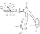
도 1은 본 실시예에 따른 수술 장치를 나타낸 사시도이다.
도 2는 본 실시예에 따른 수술 장치를 나타낸 측면도이다.
도 3은 본 실시예에 따른 수술 장치를 나타낸 단면도이다.
도 4는 본 실시예에 따른 수술 장치의 가동핸들이 조작되는 상태를 나타낸 측면도이다.
도 5는 본 실시예에 따른 수술 장치에서 생체조직이 파지되기 전, 지지 프로브의 전단과 가동 프로브의 전단이 먼저 폐쇄되는 상태를 나타낸 단면도이다.
도 6은 본 실시예에 따른 수술 장치에서 생체조직이 파지되는 상태를 나타낸 단면도이다.
도 7은 본 실시예에 따른 수술 장치에서 생체조직이 절단되는 상태를 나타낸 사시도이다.
도 8은 본 실시예에 따른 수술 장치에서 생체조직이 절단된 이후의 지지 프로브와 가동 프로브의 상태를 나타낸 사시도이다.1 is a perspective view showing a surgical device according to the present embodiment.
2 is a side view showing the surgical device according to the present embodiment.
3 is a cross-sectional view showing a surgical device according to the present embodiment.
4 is a side view showing a state in which the movable handle of the surgical device according to the present embodiment is operated.
5 is a cross-sectional view showing a state in which the front end of the support probe and the front end of the movable probe are first closed before the biological tissue is gripped in the surgical device according to the present embodiment.
6 is a cross-sectional view showing a state in which biological tissue is gripped in the surgical device according to the present embodiment.
7 is a perspective view showing a state in which the biological tissue is cut in the surgical device according to the present embodiment.
8 is a perspective view showing the state of the support probe and the movable probe after the cutting of the biological tissue in the surgical device according to the present embodiment.
이하, 본 실시예에 따른 수술 장치에 대해 첨부된 도면을 참조하여 상세히 설명하도록 한다.Hereinafter, the surgical device according to the present embodiment will be described in detail with reference to the accompanying drawings.
도 1은 본 실시예에 따른 수술 장치를 나타낸 사시도이며, 도 2는 본 실시예에 따른 수술 장치를 나타낸 측면도이며, 도 3은 본 실시예에 따른 수술 장치를 나타낸 단면도이다.1 is a perspective view showing a surgical device according to the present embodiment, Figure 2 is a side view showing a surgical device according to the present embodiment, Figure 3 is a cross-sectional view showing a surgical device according to the present embodiment.
도 1 내지 도 3을 참조하면, 본 실시예에 따른 수술 장치(100)는 지지핸들(110), 가동핸들(120), 지지관(130), 지지 프로브(140), 가동 프로브(150) 및 견인바(160)를 포함한다.1 to 3, the
지지핸들(110)에는 제 1손가락 삽입구(111)가 형성된다. 제 1손가락 삽입구(111)에는 시술자의 엄지손가락이 삽입될 수 있다. 가동핸들(120)은 지지핸들(110)에 대해 회전가능하게 결합된다. 즉, 지지핸들(110)의 상부에는 회전축(122)이 설치되고 가동핸들(120)은 회전축(122)을 중심으로 회전될 수 있도록 지지핸들(110)에 결합된다. 가동핸들(120)에는 제 2손가락 삽입구(121)가 형성된다. 제 2손가락 삽입구(121)에는 시술자의 엄지손가락을 제외한 나머지 손가락이 삽입할 수 있다.The
지지관(130)은 지지핸들(110)의 전방에 배치되어 지지핸들(110)에 결합된다. 지지관(130)의 전단은 전방을 향해 개방되며, 지지관(130)의 후단은 지지핸들(110)을 관통하여 가동핸들(120)을 향해 개방된다. 지지관(130)의 전단부에는 제 1피봇 핀(131)이 설치된다. 제 1피봇 핀(131)은 지지관(130)의 지름 방향으로 배치된다.The
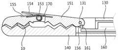
지지 프로브(140)는 지지관(130)의 전단부에 결합된다. 지지 프로브(140)의 일면에는 제 1요철(140a)이 형성된다. 제 1요철(140a)은 다수의 볼록부와, 다수의 오목부로 이루어진다. 그리고 가동 프로브(150)는 지지 프로브(140)를 향해 회전되로록 구성되는데, 지지 프로브(140)의 일면에 대향되는 가동 프로브(150)의 일면에는 제 1요철(140a)에 대응되는 제 2요철(150a)이 형성된다. 제 2요철(150a)은 가동 프로브(150)가 제 1피봇 핀(131)을 중심으로 지지 프로브(140)를 향해 회전됨에 따라 제 1요철(140a)의 오목부에 삽입되는 볼록부와, 제 1요철의 볼록부가 삽입되는 오목부로 이루어진다. 지지 프로브(140)와 가동 프로브(150)의 서로 대향되는 면에 각각 형성되는 제 1요철(140a)과 제 2요철(150a)은 지지 프로브(140)와 가동 프로브(150)의 사이에 위치하는 생체조직(10)(도 5 참조.)이 지지 프로브(140)와 가동 프로브(150)의 사이에서 이탈되는 것을 방지한다.The
한편, 가동 프로브(150)는 제 1프로브(151)와 제 2프로브(152)로 분리될 수 있다. 제 1프로브(151)는 후단부가 제 1피봇 핀(131)을 중심으로 회전되도록 지지관(130)의 전단부에 결합된다. 제 1프로브(151)의 전단부에는 제 2피봇 핀(153)이 설치된다. 제 2피봇 핀(153)은 제 1피봇 핀(131)과 동일한 방향으로 배치된다. 제 2프로브(152)는 제 2피봇 핀(153)을 중심으로 회전되도록 제 1프로브(151)에 결합된다.Meanwhile, the movable probe 150 may be separated into a
제 1프로브(151)와 제 2프로브(152)의 사이에는 탄성체(170)가 설치된다. 탄성체(170)로는 일단부가 제 1프로브(151)에 지지되고, 타단부가 제 2프로브(152)에 지지되며 제 2피봇 핀(153)의 외경부에 설치되는 토션 스프링을 사용할 수 있다.An
제 1프로브(151)가 지지 프로브(140)로부터 이격되어 있는 상태에서, 탄성체(170)는 제 2프로브(152)가 제 1프로브(151)로부터 지지 프로브(140)를 향해 기울어지는 자세가 유지되도록 한다. 따라서 탄성체(170)는 가동 프로브(150)가 지지 프로브(140)에 접촉되기 이전에 제 2프로브(152)의 전단과 지지 프로브(140)의 전단이 먼저 폐쇄되어 가동 프로브(150)와 지지 프로브(140)의 사이에 위치하는 생체조직(10)이 가동 프로브(150)가 지지 프로브(140)의 사이에서 이탈되는 것을 방지한다.In a state in which the
또한, 제 1프로브(151)에는 전방을 향해 돌출되는 가압바(154)가 형성된다. 가압바(154)는 제 1프로브(151)가 지지 프로브(140)를 향해 회전됨에 따라, 제 2프로브(152)에 작용하는 탄성력에 제 2프로브(152)를 가압하는 가압력이 부가되도록 한다. 따라서 가압바(154)는 가동 프로브(150)와 지지 프로브(140)가 생체조직을 견고하게 파지할 수 있도록 하며, 생체조직이 절단되기에 충분한 전단력이 작용되도록 한다. 제 2프로브(152)의 상부면에는 제 1프로브(151)가 지지 프로브(140)를 향해 회전됨에 따라 가압바(154)가 수용되는 수용홈(155)이 형성될 수 있다.In addition, the
한편, 견인바(160)는 지지관(130)의 내부에 삽입된다. 견인바(160)의 후단은 지지관(130)의 후방으로 노출되어 가동핸들(120)에 연결된다. 견인바(160)는 지지핸들(110)의 회전에 따라 전, 후방으로 견인되어 제 1프로브(151)가 제 1피봇 핀(131)을 중심으로 회전되도록 한다. 즉, 제 1프로브(151)의 후단부에는 견인홈(156)이 형성되며, 견인바(160)의 전단부에는 견인홈(156)에 구속되는 견인돌기(161)가 형성된다.Meanwhile, the
이에 따라, 회전축(122)을 중심으로 가동핸들(120)이 지지핸들(110)을 향해 회전되면, 견인바(160)는 후진된다. 이때, 견인홈(156)에 구속되는 견인돌기(161)는 견인바(160)와 함께 후진되어 제 1프로브(151)가 제 1피봇 핀(131)을 중심으로 지지 프로브(140)를 향해 회전되도록 한다. 이와 반대로, 회전축(122)을 중심으로 가동핸들(120)이 지지핸들(110)의 반대방향을 향해 회전되면 견인바(160)는 전진된다. 이때, 견인홈(156)에 구속되는 견인돌기(161)는 견인바(160)와 함께 전진되어 제 1프로브(151)가 지지 프로브(140)의 반대방향을 향해 회전되도록 한다.Accordingly, when the
한편, 지지 프로브(140)와 가동 프로브(150)는 전도성 재료로 이루지며, 도시 되지 않았지만, 지지 프로브(140)와 가동 프로브(150)에는 전원공급선(미도시)이 연결될 수 있다. 따라서 지지 프로브(140)와 가동 프로브(150)가 생체조직(10)을 파지함에 따라 지지 프로브(140)와 가동 프로브(150)는 통전될 수 있다. 이와 같이 지지 프로브(140)와 가동 프로브(150)의 사이가 통전되면, 생체조직(10)으로 초음파 진동 또는 고주파 전류가 가해져 생체조직(10)이 응고 및 절단 처리될 수 있다. 이와 같은 초음파 진동 또는 고주파 전류를 공급하는 구성은 이미 공지된 사항이므로 상세한 설명은 생략하도록 한다.
On the other hand, the
이하, 본 실시예에 따른 수술 장치의 동작에 대해 첨부된 도면을 참조하여 상세히 설명하도록 한다.Hereinafter, the operation of the surgical device according to the present embodiment will be described in detail with reference to the accompanying drawings.
도 4는 본 실시예에 따른 수술 장치의 가동핸들이 조작되는 상태를 나타낸 측면도이다.4 is a side view showing a state in which the movable handle of the surgical device according to the present embodiment is operated.
도 4를 참조하면, 시술자는 지지핸들(110)과 가동핸들(120)을 파지한다. 제 1손가락 삽입구(111)에 시술자의 엄지손가락이 삽입되고, 제 2손가락 삽입구(121)에 시술자의 엄지손가락을 제외한 나머지 손가락이 삽입될 수 있다.Referring to FIG. 4, the operator grips the support handle 110 and the
이때, 가동 프로브(150)는 지지 프로브(140)로부터 이격되어 전방을 향해 개방된 상태이다. 도시된 바와 같이 제 1프로브(151)는 지지 프로브(140)로에 대해 제 1피봇 핀(131)을 중심으로 대략 45도 정도의 각도로 기울어져 지지 프로브(140)로부터 이격되어 있으며, 제 2프로브(152)는 제 1프로브(151)로부터 지지 프로브(140)를 향해 기울어져 지지 프로브(140)와 거의 평행한 자세를 취하고 있다.At this time, the movable probe 150 is spaced apart from the
이와 같이 시술자가 지지핸들(110) 및 가동핸들(120)을 파지한 상태에서, 지지관(130)은 시술 대상이 되는 생체조직(10)을 향해 체내로 삽입된다. 지지관(130)이 체내로 삽입됨에 따라 지지 프로브(140)와 가동 프로브(150)의 사이에 생체조직(10)이 위치할 수 있다.As described above, in the state in which the operator grips the support handle 110 and the
시술자는 생체조직(10)을 파지하기 위해 가동핸들(120)을 조작한다.The operator manipulates the
도 5는 본 실시예에 따른 수술 장치에서 생체조직이 파지되기 전, 지지 프로브의 전단과 가동 프로브의 전단이 먼저 폐쇄되는 상태를 나타낸 단면도이다.5 is a cross-sectional view showing a state in which the front end of the support probe and the front end of the movable probe are first closed before the biological tissue is gripped in the surgical device according to the present embodiment.
도 5를 참조하면, 시술자의 조작에 의해 가동핸들(120)은 회전축(122)을 중심으로 지지핸들(110)을 향해 회전된다. 가동핸들(120)이 회전됨에 따라 견인바(160)는 후진된다. 견인홈(156)에 구속되는 견인돌기(161)는 견인바(160)와 함께 후진되며, 제 1프로브(151)는 제 1피봇 핀(131)을 중심으로 지지 프로브(140)를 향해 회전된다.Referring to FIG. 5, the
제 2프로브(152)는 제 2피봇 핀(153)에 의해 제 1프로브(151)에 결합되고 탄성체(170)에 의해 제 1프로브(151)로부터 탄성지지되므로, 제 1프로브(151)와 함께 회전되어 그 전단이 지지 프로브(140)의 전단에 먼저 접촉된다. 따라서 생체조직(10)이 지지 프로브(140)와 가동 프로브(150)의 사이에 위치하는 상태에서 지지 프로브(140)의 전단과 가동 프로브(150)의 전단이 폐쇄되어 생체조직(10)이 지지 프로브(140)와 가동 프로브(150)로부터 이탈되는 것이 방지된다.Since the
도 6은 본 실시예에 따른 수술 장치에서 생체조직이 파지되는 상태를 나타낸 단면도이며, 도 7은 본 실시예에 따른 수술 장치에서 생체조직이 절단되는 상태를 나타낸 사시도이며, 도 8은 본 실시예에 따른 수술 장치에서 생체조직이 절단된 이후의 지지 프로브와 가동 프로브의 상태를 나타낸 사시도이다.6 is a cross-sectional view showing a state in which the living tissue is gripped in the surgical device according to the present embodiment, Figure 7 is a perspective view showing a state in which the living tissue is cut in the surgical device according to the present embodiment, Figure 8 is an embodiment The perspective view showing the state of the support probe and the movable probe after the tissue is cut in the surgical device according to the.
도 6 내지 도 8을 참조하면, 계속해서 가동핸들(120)이 지지핸들(110)을 향해 회전되면, 제 1프로브(151)가 지지 프로브(140)를 향해 더 회전된다. 이때, 제 2프로브(152)의 전단은 지지 프로브(140)에 접촉되어 있으므로, 제 2프로브(152)는 후단이 지지 프로브(140)를 향해 회전된다. 이에 따라 제 1프로브(151)는 지지 프로브(140)와 함께 생체조직을 가압하여 지지 프로브(140)와 가동 프로브(150)의 사이에 위치하는 생체조직(10)이 파지되도록 한다.6 to 8, when the
이때, 제 1프로브(151)가 지지 프로브(140)를 향해 더 회전됨에 따라 가압바(154)는 제 2프로브(152)를 가압한다. 따라서 탄성체(170)에 의한 탄성력에, 가압바(154)에 의한 가압력이 제 2프로브(152)에 부가되어 제 2프로브(152)는 생체조직(10)을 절단하기에 충분한 전단력을 가지고 생체조직(10)을 가압할 수 있다.At this time, as the
이때, 도시되지 않은 전원공급선(미도시)에 의해 전원이 공급되면, 지지 프로브(140)와 가동 프로브(150)는 서로 통전될 수 있다. 따라서 생체조직(10)에는 초음파 진동 또는 고주파 전류가 전달되고 지지 프로브(140)와 가동 프로브(150)의 전단력에 의해 응고되고 절단될 수 있다.At this time, when the power is supplied by a power supply line (not shown) not shown, the
상술 한 바와 같이, 본 실시예에 따른 수술 장치(100)는 지지 프로브(140)와 가동 프로브(150)에 각각 제 1요철(140a)과 제 2요철(150a)이 형성되며, 가동 프로브(150)가 지지 프로브(140)를 향해 회전되는 과정에서 제 2프로브(152)의 전단이 지지 프로브(140)의 전단에 먼저 접촉되어 지지 프로브(140)와 가동 프로브(150)의 전단을 폐쇄한다.As described above, in the
따라서 본 실시예에 따른 수술 장치(100)는 지지 프로브(140)와 가동 프로브(150)의 사이에 위치하는 생체조직(10)이 지지 프로브(140)와 가동 프로브(150)의 사이에서 이탈되는 것이 방지되어 생체조직(10)이 원활하게 파지될 수 있도록 한다.Therefore, in the
또한, 본 실시예에 따른 수술 장치(100)는 제 1프로브(151)로부터 제 2프로브(152)를 탄성지지하고, 가압바(154)에 의해 제 2프로브(152)가 가압되도록 하여 생체조직(10)이 원활하게 절단되도록 한다.In addition, the
따라서 본 실시예에 따른 수술 장치(100)는 생체조직(10)을 파지하기 위한 용도로 사용될 수 있을 뿐만 아니라, 초음파를 이용한 수술에 사용되어 생체조직(10)이 원활하게 응고되도록 하며, 응고된 생체조직(10)이 원활하게 절단되도록 한다.
Therefore, the
100 :수술 장치 110 : 지지핸들
120 : 가동핸들122 : 회전축
130 : 지지관131 : 제 1피봇 핀
140 : 지지 프로브150 : 가동 프로브
151 : 제 1프로브152 : 제 2프로브
153 : 제 2피봇 핀154 : 가압바
160 : 견인바170 : 탄성체100: surgical device 110: support handle
120: movable handle 122: rotating shaft
130: support tube 131: first pivot pin
140: support probe 150: movable probe
151: first probe 152: second probe
153: second pivot pin 154: pressure bar
160: drawbar 170: elastic body
Claims (8)
Translated fromKorean상기 지지관에 지지되며, 제 1요철이 형성되는 지지 프로브(probe),
상기 지지관의 전단부에 상기 지지관의 지름방향으로 결합되는 제 1피봇 핀,
상기 제 1피봇 핀을 중심으로 회전가능하게 상기 지지관의 전단부에 결합되며, 상기 제 1요철의 오목부에 대응되는 볼록부와 상기 제 1요철의 볼록부에 대응되는 오목부로 이루어지는 제 2요철이 형성되는 가동 프로브 및
상기 지지관의 내부에 삽입되어 전단이 상기 가동 프로브에 연결되고 후단이 상기 지지관의 후방으로 노출되며, 상기 가동 프로브가 상기 제 1피봇 핀을 중심으로 회전되도록 견인되는 견인바를 포함하며,
상기 가동 프로브는
상기 제 1피봇 핀을 중심으로 회전되도록 상기 지지관의 전단부에 결합되는 제 1프로브 및
상기 제 1피봇 핀과 동일한 방향으로 배치되는 제 2피봇 핀을 중심으로 회전되도록 상기 제 1프로브에 결합되는 제 2프로브를 포함하는 것을 특징으로 하는 수술 장치.Support tube with open front and rear ends,
A support probe supported by the support tube and having a first unevenness formed therein;
A first pivot pin coupled to the front end of the support tube in a radial direction of the support tube,
A second concave-convex coupled to a front end of the support tube rotatably around the first pivot pin, the convex portion corresponding to the concave portion of the first concave-convex portion and the concave portion corresponding to the convex portion of the first concave-convex portion This is a movable probe and
A pull bar inserted into the support tube and having a front end connected to the movable probe and a rear end exposed to the rear of the support tube, the pull bar being pulled to rotate about the first pivot pin,
The movable probe
A first probe coupled to the front end of the support tube so as to rotate about the first pivot pin;
And a second probe coupled to the first probe to rotate about a second pivot pin disposed in the same direction as the first pivot pin.
상기 지지관의 후방에 배치되어 상기 지지관을 지지하는 지지핸들,
상기 견인바의 후단이 연결되고 상기 지지핸들에 회전가능하게 설치되어 상기 견인바가 견인되도록 상기 지지핸들에 대해 회전되는 가동핸들을 더 포함하는 것을 특징으로 하는 수술 장치.The method of claim 1,
A support handle disposed at the rear of the support tube to support the support tube;
And a movable handle connected to the rear end of the draw bar and rotatably installed on the support handle to rotate with respect to the support handle so that the draw bar is towed.
일단부가 상기 제 1프로브에 지지되고 타단부가 상기 제 2프로브에 지지되어 상기 제 2피봇 핀의 외경부에 설치되는 토션 스프링인 것을 특징으로 하는 수술 장치.The method of claim 4, wherein the elastic body
And a torsion spring having one end supported by the first probe and the other end supported by the second probe and installed on an outer diameter portion of the second pivot pin.
상기 제 1프로브로부터 상기 지지 프로브를 향해 기울어지며,
상기 제 1프로브가 상기 제 1피봇 핀을 기준으로 상기 지지 프로브를 향해 회전됨에 따라 상기 제 1프로브와 함께 상기 지지 프로브에 접촉되는 것을 특징으로 하는 수술 장치.The method of claim 1, wherein the second probe
Tilted from the first probe toward the support probe,
And the first probe contacts the support probe with the first probe as the first probe is rotated toward the support probe with respect to the first pivot pin.
상기 가동 프로브에는 견인홈이 형성되며,
상기 견인홈에 구속되어 상기 견인바의 견인에 따라 상기 가동 프로브가 상기 제 1피봇 핀을 중심으로 회전되도록 상기 견인바로부터 상기 가동 프로브를 향해 돌출되는 견인돌기를 더 포함하는 것을 수술 장치.
The method of claim 1,
Towing groove is formed in the movable probe,
And a traction protrusion protruding from the traction bar toward the movable probe such that the movable probe is rotated about the first pivot pin in response to the traction of the traction bar.
Priority Applications (1)
| Application Number | Priority Date | Filing Date | Title |
|---|---|---|---|
| KR1020110055600AKR101298237B1 (en) | 2011-06-09 | 2011-06-09 | Surgical devices |
Applications Claiming Priority (1)
| Application Number | Priority Date | Filing Date | Title |
|---|---|---|---|
| KR1020110055600AKR101298237B1 (en) | 2011-06-09 | 2011-06-09 | Surgical devices |
Publications (2)
| Publication Number | Publication Date |
|---|---|
| KR20120136584A KR20120136584A (en) | 2012-12-20 |
| KR101298237B1true KR101298237B1 (en) | 2013-08-22 |
Family
ID=47903935
Family Applications (1)
| Application Number | Title | Priority Date | Filing Date |
|---|---|---|---|
| KR1020110055600AExpired - Fee RelatedKR101298237B1 (en) | 2011-06-09 | 2011-06-09 | Surgical devices |
Country Status (1)
| Country | Link |
|---|---|
| KR (1) | KR101298237B1 (en) |
Cited By (28)
| Publication number | Priority date | Publication date | Assignee | Title |
|---|---|---|---|---|
| WO2021137010A1 (en)* | 2019-12-30 | 2021-07-08 | Ethicon Llc | Variation in electrode parameters and deflectable electrode to modify energy density and tissue interaction |
| EP3895644A1 (en)* | 2020-04-15 | 2021-10-20 | Erbe Elektromedizin GmbH | Surgical instrument |
| US11766287B2 (en) | 2015-09-30 | 2023-09-26 | Cilag Gmbh International | Methods for operating generator for digitally generating electrical signal waveforms and surgical instruments |
| US11779387B2 (en) | 2019-12-30 | 2023-10-10 | Cilag Gmbh International | Clamp arm jaw to minimize tissue sticking and improve tissue control |
| US11786294B2 (en) | 2019-12-30 | 2023-10-17 | Cilag Gmbh International | Control program for modular combination energy device |
| US11786291B2 (en) | 2019-12-30 | 2023-10-17 | Cilag Gmbh International | Deflectable support of RF energy electrode with respect to opposing ultrasonic blade |
| US11812957B2 (en) | 2019-12-30 | 2023-11-14 | Cilag Gmbh International | Surgical instrument comprising a signal interference resolution system |
| US11871982B2 (en) | 2009-10-09 | 2024-01-16 | Cilag Gmbh International | Surgical generator for ultrasonic and electrosurgical devices |
| US11871955B2 (en) | 2012-06-29 | 2024-01-16 | Cilag Gmbh International | Surgical instruments with articulating shafts |
| US11896280B2 (en) | 2016-01-15 | 2024-02-13 | Cilag Gmbh International | Clamp arm comprising a circuit |
| US11937863B2 (en) | 2019-12-30 | 2024-03-26 | Cilag Gmbh International | Deflectable electrode with variable compression bias along the length of the deflectable electrode |
| US11944366B2 (en) | 2019-12-30 | 2024-04-02 | Cilag Gmbh International | Asymmetric segmented ultrasonic support pad for cooperative engagement with a movable RF electrode |
| US11950797B2 (en) | 2019-12-30 | 2024-04-09 | Cilag Gmbh International | Deflectable electrode with higher distal bias relative to proximal bias |
| US11974801B2 (en) | 2019-12-30 | 2024-05-07 | Cilag Gmbh International | Electrosurgical instrument with flexible wiring assemblies |
| US11974772B2 (en) | 2016-01-15 | 2024-05-07 | Cilag GmbH Intemational | Modular battery powered handheld surgical instrument with variable motor control limits |
| US11986201B2 (en) | 2019-12-30 | 2024-05-21 | Cilag Gmbh International | Method for operating a surgical instrument |
| US11998230B2 (en) | 2016-11-29 | 2024-06-04 | Cilag Gmbh International | End effector control and calibration |
| US12023086B2 (en) | 2019-12-30 | 2024-07-02 | Cilag Gmbh International | Electrosurgical instrument for delivering blended energy modalities to tissue |
| US12076006B2 (en) | 2019-12-30 | 2024-09-03 | Cilag Gmbh International | Surgical instrument comprising an orientation detection system |
| US12082808B2 (en) | 2019-12-30 | 2024-09-10 | Cilag Gmbh International | Surgical instrument comprising a control system responsive to software configurations |
| RU2827951C2 (en)* | 2020-04-15 | 2024-10-04 | Эрбе Электромедицин Гмбх | Surgical instrument |
| US12114912B2 (en) | 2019-12-30 | 2024-10-15 | Cilag Gmbh International | Non-biased deflectable electrode to minimize contact between ultrasonic blade and electrode |
| US12193698B2 (en) | 2016-01-15 | 2025-01-14 | Cilag Gmbh International | Method for self-diagnosing operation of a control switch in a surgical instrument system |
| US12239360B2 (en) | 2016-01-15 | 2025-03-04 | Cilag Gmbh International | Modular battery powered handheld surgical instrument with selective application of energy based on button displacement, intensity, or local tissue characterization |
| US12262937B2 (en) | 2019-12-30 | 2025-04-01 | Cilag Gmbh International | User interface for surgical instrument with combination energy modality end-effector |
| US12336747B2 (en) | 2019-12-30 | 2025-06-24 | Cilag Gmbh International | Method of operating a combination ultrasonic / bipolar RF surgical device with a combination energy modality end-effector |
| US12343063B2 (en) | 2019-12-30 | 2025-07-01 | Cilag Gmbh International | Multi-layer clamp arm pad for enhanced versatility and performance of a surgical device |
| US12349961B2 (en) | 2019-12-30 | 2025-07-08 | Cilag Gmbh International | Electrosurgical instrument with electrodes operable in bipolar and monopolar modes |
Families Citing this family (1)
| Publication number | Priority date | Publication date | Assignee | Title |
|---|---|---|---|---|
| KR102706201B1 (en)* | 2022-06-16 | 2024-09-13 | 울산대학교 산학협력단 | Resection device for surgery |
Citations (3)
| Publication number | Priority date | Publication date | Assignee | Title |
|---|---|---|---|---|
| JPH1028693A (en)* | 1996-03-29 | 1998-02-03 | Ethicon Endo Surgery Inc | Bipolar scissors |
| US7264618B2 (en)* | 2002-08-02 | 2007-09-04 | Olympus Corporation | Ultrasonic treatment apparatus |
| KR20090073046A (en)* | 2007-12-28 | 2009-07-02 | 올림푸스 메디칼 시스템즈 가부시키가이샤 | Surgical surgical device |
- 2011
- 2011-06-09KRKR1020110055600Apatent/KR101298237B1/ennot_activeExpired - Fee Related
Patent Citations (3)
| Publication number | Priority date | Publication date | Assignee | Title |
|---|---|---|---|---|
| JPH1028693A (en)* | 1996-03-29 | 1998-02-03 | Ethicon Endo Surgery Inc | Bipolar scissors |
| US7264618B2 (en)* | 2002-08-02 | 2007-09-04 | Olympus Corporation | Ultrasonic treatment apparatus |
| KR20090073046A (en)* | 2007-12-28 | 2009-07-02 | 올림푸스 메디칼 시스템즈 가부시키가이샤 | Surgical surgical device |
Cited By (36)
| Publication number | Priority date | Publication date | Assignee | Title |
|---|---|---|---|---|
| US11871982B2 (en) | 2009-10-09 | 2024-01-16 | Cilag Gmbh International | Surgical generator for ultrasonic and electrosurgical devices |
| US12408967B2 (en) | 2009-10-09 | 2025-09-09 | Cilag Gmbh International | Surgical generator for ultrasonic and electrosurgical devices |
| US11871955B2 (en) | 2012-06-29 | 2024-01-16 | Cilag Gmbh International | Surgical instruments with articulating shafts |
| US11766287B2 (en) | 2015-09-30 | 2023-09-26 | Cilag Gmbh International | Methods for operating generator for digitally generating electrical signal waveforms and surgical instruments |
| US12239360B2 (en) | 2016-01-15 | 2025-03-04 | Cilag Gmbh International | Modular battery powered handheld surgical instrument with selective application of energy based on button displacement, intensity, or local tissue characterization |
| US11974772B2 (en) | 2016-01-15 | 2024-05-07 | Cilag GmbH Intemational | Modular battery powered handheld surgical instrument with variable motor control limits |
| US12402906B2 (en) | 2016-01-15 | 2025-09-02 | Cilag Gmbh International | Modular battery powered handheld surgical instrument and methods therefor |
| US12201339B2 (en) | 2016-01-15 | 2025-01-21 | Cilag Gmbh International | Modular battery powered handheld surgical instrument with selective application of energy based on tissue characterization |
| US12193698B2 (en) | 2016-01-15 | 2025-01-14 | Cilag Gmbh International | Method for self-diagnosing operation of a control switch in a surgical instrument system |
| US11896280B2 (en) | 2016-01-15 | 2024-02-13 | Cilag Gmbh International | Clamp arm comprising a circuit |
| US11998230B2 (en) | 2016-11-29 | 2024-06-04 | Cilag Gmbh International | End effector control and calibration |
| US11944366B2 (en) | 2019-12-30 | 2024-04-02 | Cilag Gmbh International | Asymmetric segmented ultrasonic support pad for cooperative engagement with a movable RF electrode |
| US12114912B2 (en) | 2019-12-30 | 2024-10-15 | Cilag Gmbh International | Non-biased deflectable electrode to minimize contact between ultrasonic blade and electrode |
| US11950797B2 (en) | 2019-12-30 | 2024-04-09 | Cilag Gmbh International | Deflectable electrode with higher distal bias relative to proximal bias |
| US11974801B2 (en) | 2019-12-30 | 2024-05-07 | Cilag Gmbh International | Electrosurgical instrument with flexible wiring assemblies |
| US11937863B2 (en) | 2019-12-30 | 2024-03-26 | Cilag Gmbh International | Deflectable electrode with variable compression bias along the length of the deflectable electrode |
| US11986234B2 (en) | 2019-12-30 | 2024-05-21 | Cilag Gmbh International | Surgical system communication pathways |
| US11986201B2 (en) | 2019-12-30 | 2024-05-21 | Cilag Gmbh International | Method for operating a surgical instrument |
| EP3845169A3 (en)* | 2019-12-30 | 2021-12-01 | Ethicon LLC | Variation in electrode parameters and deflectable electrode to modify energy density and tissue interaction |
| US12023086B2 (en) | 2019-12-30 | 2024-07-02 | Cilag Gmbh International | Electrosurgical instrument for delivering blended energy modalities to tissue |
| US12053224B2 (en) | 2019-12-30 | 2024-08-06 | Cilag Gmbh International | Variation in electrode parameters and deflectable electrode to modify energy density and tissue interaction |
| US12076006B2 (en) | 2019-12-30 | 2024-09-03 | Cilag Gmbh International | Surgical instrument comprising an orientation detection system |
| US12082808B2 (en) | 2019-12-30 | 2024-09-10 | Cilag Gmbh International | Surgical instrument comprising a control system responsive to software configurations |
| US11786291B2 (en) | 2019-12-30 | 2023-10-17 | Cilag Gmbh International | Deflectable support of RF energy electrode with respect to opposing ultrasonic blade |
| US11786294B2 (en) | 2019-12-30 | 2023-10-17 | Cilag Gmbh International | Control program for modular combination energy device |
| US11779387B2 (en) | 2019-12-30 | 2023-10-10 | Cilag Gmbh International | Clamp arm jaw to minimize tissue sticking and improve tissue control |
| US11812957B2 (en) | 2019-12-30 | 2023-11-14 | Cilag Gmbh International | Surgical instrument comprising a signal interference resolution system |
| WO2021137010A1 (en)* | 2019-12-30 | 2021-07-08 | Ethicon Llc | Variation in electrode parameters and deflectable electrode to modify energy density and tissue interaction |
| US12349961B2 (en) | 2019-12-30 | 2025-07-08 | Cilag Gmbh International | Electrosurgical instrument with electrodes operable in bipolar and monopolar modes |
| US12343063B2 (en) | 2019-12-30 | 2025-07-01 | Cilag Gmbh International | Multi-layer clamp arm pad for enhanced versatility and performance of a surgical device |
| US12262937B2 (en) | 2019-12-30 | 2025-04-01 | Cilag Gmbh International | User interface for surgical instrument with combination energy modality end-effector |
| US12336747B2 (en) | 2019-12-30 | 2025-06-24 | Cilag Gmbh International | Method of operating a combination ultrasonic / bipolar RF surgical device with a combination energy modality end-effector |
| US12251154B2 (en) | 2020-04-15 | 2025-03-18 | Erbe Elektromedizin Gmbh | Surgical instrument |
| JP7641805B2 (en) | 2020-04-15 | 2025-03-07 | エルベ エレクトロメディジン ゲーエムベーハー | Surgical instruments |
| RU2827951C2 (en)* | 2020-04-15 | 2024-10-04 | Эрбе Электромедицин Гмбх | Surgical instrument |
| EP3895644A1 (en)* | 2020-04-15 | 2021-10-20 | Erbe Elektromedizin GmbH | Surgical instrument |
Also Published As
| Publication number | Publication date |
|---|---|
| KR20120136584A (en) | 2012-12-20 |
Similar Documents
| Publication | Publication Date | Title |
|---|---|---|
| KR101298237B1 (en) | Surgical devices | |
| JP3686765B2 (en) | Ultrasonic treatment device | |
| JP4758519B2 (en) | Surgical instruments | |
| CN103702625B (en) | Detachable surgery pliers | |
| US7431720B2 (en) | Multi-function clamping device with stapler and ablation heads | |
| JP2504936B2 (en) | Medical forceps | |
| CN101176681B (en) | Surgical forceps with electrode and cable | |
| US11452560B2 (en) | Treatment tool with jaws | |
| JP2001057985A (en) | Ultrasonic treating tool | |
| EP2486862A3 (en) | Electrical surgical instrument | |
| CN108601602B (en) | Endoscopic treatment device | |
| JP2004057588A (en) | Surgical treatment instrument | |
| CN107427312B (en) | Combined medical apparatus | |
| CN104434298A (en) | Bipolar surgical instrument with tissue limiting piece | |
| JP2008508965A (en) | Electrosurgical instrument | |
| JP2015198933A (en) | Medical treatment tool gripping tool | |
| US20180296238A1 (en) | Surgical instrument and connector | |
| JP2015024038A (en) | Operation input device for endoscope treatment tool | |
| KR20210023786A (en) | laparoscopic instrument | |
| KR20160039605A (en) | Bipolar surgical instrument | |
| JP2013070861A (en) | forceps | |
| CN212281619U (en) | Electric coagulation forceps | |
| KR101365919B1 (en) | Ultrasound operating apparatus | |
| US20160345993A1 (en) | Surgical instruments and devices and methods facilitating the manufacture of the same | |
| CN104382622A (en) | Arc needle holding forceps that resets |
Legal Events
| Date | Code | Title | Description |
|---|---|---|---|
| A201 | Request for examination | ||
| PA0109 | Patent application | St.27 status event code:A-0-1-A10-A12-nap-PA0109 | |
| PA0201 | Request for examination | St.27 status event code:A-1-2-D10-D11-exm-PA0201 | |
| D13-X000 | Search requested | St.27 status event code:A-1-2-D10-D13-srh-X000 | |
| D14-X000 | Search report completed | St.27 status event code:A-1-2-D10-D14-srh-X000 | |
| PE0902 | Notice of grounds for rejection | St.27 status event code:A-1-2-D10-D21-exm-PE0902 | |
| PG1501 | Laying open of application | St.27 status event code:A-1-1-Q10-Q12-nap-PG1501 | |
| E13-X000 | Pre-grant limitation requested | St.27 status event code:A-2-3-E10-E13-lim-X000 | |
| P11-X000 | Amendment of application requested | St.27 status event code:A-2-2-P10-P11-nap-X000 | |
| P13-X000 | Application amended | St.27 status event code:A-2-2-P10-P13-nap-X000 | |
| R17-X000 | Change to representative recorded | St.27 status event code:A-3-3-R10-R17-oth-X000 | |
| E701 | Decision to grant or registration of patent right | ||
| PE0701 | Decision of registration | St.27 status event code:A-1-2-D10-D22-exm-PE0701 | |
| GRNT | Written decision to grant | ||
| PR0701 | Registration of establishment | St.27 status event code:A-2-4-F10-F11-exm-PR0701 | |
| PR1002 | Payment of registration fee | St.27 status event code:A-2-2-U10-U11-oth-PR1002 Fee payment year number:1 | |
| PG1601 | Publication of registration | St.27 status event code:A-4-4-Q10-Q13-nap-PG1601 | |
| FPAY | Annual fee payment | Payment date:20160805 Year of fee payment:4 | |
| PR1001 | Payment of annual fee | St.27 status event code:A-4-4-U10-U11-oth-PR1001 Fee payment year number:4 | |
| P22-X000 | Classification modified | St.27 status event code:A-4-4-P10-P22-nap-X000 | |
| FPAY | Annual fee payment | Payment date:20170811 Year of fee payment:5 | |
| PR1001 | Payment of annual fee | St.27 status event code:A-4-4-U10-U11-oth-PR1001 Fee payment year number:5 | |
| FPAY | Annual fee payment | Payment date:20180813 Year of fee payment:6 | |
| PR1001 | Payment of annual fee | St.27 status event code:A-4-4-U10-U11-oth-PR1001 Fee payment year number:6 | |
| P22-X000 | Classification modified | St.27 status event code:A-4-4-P10-P22-nap-X000 | |
| P22-X000 | Classification modified | St.27 status event code:A-4-4-P10-P22-nap-X000 | |
| FPAY | Annual fee payment | Payment date:20190808 Year of fee payment:7 | |
| PR1001 | Payment of annual fee | St.27 status event code:A-4-4-U10-U11-oth-PR1001 Fee payment year number:7 | |
| PR1001 | Payment of annual fee | St.27 status event code:A-4-4-U10-U11-oth-PR1001 Fee payment year number:8 | |
| PC1903 | Unpaid annual fee | St.27 status event code:A-4-4-U10-U13-oth-PC1903 Not in force date:20210814 Payment event data comment text:Termination Category : DEFAULT_OF_REGISTRATION_FEE | |
| PC1903 | Unpaid annual fee | St.27 status event code:N-4-6-H10-H13-oth-PC1903 Ip right cessation event data comment text:Termination Category : DEFAULT_OF_REGISTRATION_FEE Not in force date:20210814 |