KR101297024B1 - Method and apparatus for fault diagnosis network of car using can communication - Google Patents
Method and apparatus for fault diagnosis network of car using can communicationDownload PDFInfo
- Publication number
- KR101297024B1 KR101297024B1KR1020110132176AKR20110132176AKR101297024B1KR 101297024 B1KR101297024 B1KR 101297024B1KR 1020110132176 AKR1020110132176 AKR 1020110132176AKR 20110132176 AKR20110132176 AKR 20110132176AKR 101297024 B1KR101297024 B1KR 101297024B1
- Authority
- KR
- South Korea
- Prior art keywords
- ecu
- message
- failure diagnosis
- failure
- master
- Prior art date
- Legal status (The legal status is an assumption and is not a legal conclusion. Google has not performed a legal analysis and makes no representation as to the accuracy of the status listed.)
- Active
Links
Images


Classifications
- H—ELECTRICITY
- H04—ELECTRIC COMMUNICATION TECHNIQUE
- H04L—TRANSMISSION OF DIGITAL INFORMATION, e.g. TELEGRAPHIC COMMUNICATION
- H04L43/00—Arrangements for monitoring or testing data switching networks
- H04L43/08—Monitoring or testing based on specific metrics, e.g. QoS, energy consumption or environmental parameters
- H04L43/0805—Monitoring or testing based on specific metrics, e.g. QoS, energy consumption or environmental parameters by checking availability
- H04L43/0817—Monitoring or testing based on specific metrics, e.g. QoS, energy consumption or environmental parameters by checking availability by checking functioning
- H—ELECTRICITY
- H04—ELECTRIC COMMUNICATION TECHNIQUE
- H04L—TRANSMISSION OF DIGITAL INFORMATION, e.g. TELEGRAPHIC COMMUNICATION
- H04L12/00—Data switching networks
- H04L12/28—Data switching networks characterised by path configuration, e.g. LAN [Local Area Networks] or WAN [Wide Area Networks]
- H04L12/40—Bus networks
- H04L2012/40208—Bus networks characterized by the use of a particular bus standard
- H04L2012/40215—Controller Area Network CAN
- H—ELECTRICITY
- H04—ELECTRIC COMMUNICATION TECHNIQUE
- H04L—TRANSMISSION OF DIGITAL INFORMATION, e.g. TELEGRAPHIC COMMUNICATION
- H04L12/00—Data switching networks
- H04L12/28—Data switching networks characterised by path configuration, e.g. LAN [Local Area Networks] or WAN [Wide Area Networks]
- H04L12/40—Bus networks
- H04L2012/40267—Bus for use in transportation systems
- H04L2012/40273—Bus for use in transportation systems the transportation system being a vehicle
Landscapes
- Engineering & Computer Science (AREA)
- Environmental & Geological Engineering (AREA)
- Computer Networks & Wireless Communication (AREA)
- Signal Processing (AREA)
- Small-Scale Networks (AREA)
Abstract
Translated fromKoreanDescription
Translated fromKorean본 발명은 자동차 네트워크 시스템에 및 방법에 관한 것으로서 더욱 상세하게는 복수의 전자제어유니트(Electric Control Unit, ECU)의 고장을 진단하기 위한 메시지를 일괄 송신하고 결과 메시지를 일괄 수신함으로써, BCU의 고장진단을 수행하기 위한 캔통신을 이용한 자동차 고장진단 네트워크 시스템 및 방법에 관한 것이다.The present invention relates to a vehicle network system and method, and more particularly, to diagnose a failure of a BCU by collectively transmitting a message for diagnosing a failure of a plurality of electric control units (ECUs) and receiving a result message collectively. The present invention relates to a vehicle fault diagnosis network system and method using CAN communication.
최근 들어, 전자제어기술의 비약적인 발전에 따라 자동차에서도 기계적인 방법에 의해 동작하던 각종 장치들이 운전자의 편리성 및 운행의 안전성 등의 이유로 전기적인 방법에 의해 구동되고 있으며, 자동차의 시스템은 점차 고도화되고 최첨단화되어 가고 있다.Recently, with the rapid development of electronic control technology, various devices that were operated by mechanical methods in automobiles are being driven by electrical methods due to driver convenience and driving safety, and the system of automobiles is gradually advanced. It is becoming more advanced.
또한, 최근 들어 자동차에는 텔레매틱스 장치를 장착하여 차량위치정보 서비스, 차량도난 및 사고 감지, 원격 차량 진단, 긴급 구난, 교통정보 서비스와 더불어 무선인터넷을 이용한 모바일오피스 구현, 전자 메일 서비스 등을 제공하도록하고 있다.In addition, in recent years, the vehicle is equipped with a telematics device to provide vehicle location information service, vehicle theft and accident detection, remote vehicle diagnosis, emergency rescue, traffic information service, mobile office using wireless internet, and e-mail service. have.
텔레매틱스(telematics)는 통신(telecommunication)과 정보과학(informa- tion)을 합친 용어로 자동차와 컴퓨터·이통 통신 기술의 결합을 의미하는 것으로 이동통신과 인터넷 기술을 기반으로 자동차에 시기 적절한 위치정보 기반의 안전서비스, 사무환경을 제공을 통한 생산성 향상 서비스 및 금융, 예약, 상품구입, 기타 개인화된 서비스 등을 제공하는 것을 말한다.Telematics is a combination of telecommunication and information science. It means a combination of automobile, computer and telecommunication technologies. It is based on mobile communication and internet technology. Security services, productivity improvement services through providing an office environment, finance, reservations, purchase of goods, and other personalized services.
텔레매틱스의 대표적인 서비스는 네비게이션 기능, 실시간 교통정보 제공, 응급구조 그리고 각종 엔터테인먼트와 관련된 분야를 들 수 있다.Typical services of Telematics include navigation, real-time traffic information, emergency rescue, and various entertainment-related fields.
이와 같이 자동차가 점차 첨단화되면서 자동차의 고장형태도 다양화되고있으며, 이를 위한 고장 점검기술 및 고장진단 기술도 날로 향상되고 있다.As the automobile is gradually advanced, the failure forms of the automobiles are diversified, and the failure inspection technique and the diagnosis technique for the same are being improved day by day.
현재 시판되고 있는 대부분의 자동차에는 각종 센서로부터의 감지신호를 입력받아 이를 기초로 엔진의 동작을 제어하는 엔진 ECU(ENGINE ECU), 자동변속기의 동작을 제어하는 A/TM ECU(Automatic Transmission ECU), 브레이크의 동작을 제어하는 ABS ECU(Anti-lock Break System ECU) 등의 많은 전자제어유니트(ECU)들을 가지고 있다.Most of the vehicles currently on the market receive sensing signals from various sensors based on the engine ECU (ENGINE ECU) to control the operation of the engine, A / TM ECU (Automatic Transmission ECU) to control the operation of the automatic transmission, There are many electronic control units (ECUs), such as the Anti-lock Break System ECU (ABS ECU), which controls the operation of the brakes.
이와 같은 다수의 전자제어유니트(ECU)들 각각은 자기진단 기능을 가지고 있어서, 진단대상 장치에 부착된 각종센서로부터 감지신호를 입력받아 각 장치의 기능상태를 검출한 다음 그에 대응하는 진단코드를 내부의 메모리에 저장하고 있게 되며, 전자제어유니트에 저장되어 있는 진단코드는 다양한 방법에 의해 외부로 출력되도록 되어 있다.Each of these electronic control units (ECUs) has a self-diagnostic function, receives a detection signal from various sensors attached to the device to be detected, detects the functional state of each device, and then inserts a corresponding diagnostic code. The diagnostic code stored in the electronic control unit is output to the outside by various methods.
도 1은 종래의 자동차용 고장진단 시스템을 개략적으로 도시한 블록도이다.1 is a block diagram schematically showing a conventional vehicle troubleshooting system.
도 1을 참조하면, 종래의 자동차용 고장진단 시스템(100)은 제1 ECU 내지 제n ECU개로 구성된 복수의 ECU(110)와, 복수의 ECU(110)와 캔(Controller Area Network, CAN) 프로토콜로 통신을 수행하여 문제가 발생한 ECU 정보를 저장하는 마스터(Master) ECU(110)를 포함한다.Referring to FIG. 1, a conventional
도 1과 같이 구성된 종래의 자동차용 고장진단 시스템(100)의 동작은 다음과 같다.The operation of the conventional
우선, 두 개의 데이터 라인인 CAN Txd(a)와 CAN Rxd(b) 각각은 서로 다른 반전된 신호를 사용한다.First, each of the two data lines CAN Txd (a) and CAN Rxd (b) uses different inverted signals.
따라서 마스터 ECU(110)는 a로 제1 ECU의 고장상태를 알기 위한 체크메시지를 제1 ECU로 송신한다. 이 때 전송되는 메시지는 제1 ECU가 인식이 가능한 고유아이디를 포함한다.Therefore, the
그러면, 제1 ECU는 고장상태 유무에 따른 응답메시지를 b를 통해 마스터 ECU(120)로 송신하면, 마스터 ECU(110)는 응답메시지를 통해 제1 ECU의 고장유무를 확인할 수 있다.Then, when the first ECU transmits a response message according to the failure state to the
마찬가지로 마스터 ECU(12)는 제2 ECU 내지 제N ECU까지 순차적으로 송신하고, 각각의 응답메시지를 수신하여 복수의 ECU(110)의 고장상태를 확인할 수 있다.Likewise, the master ECU 12 may sequentially transmit the second ECU to the N-th ECU, and may receive failure responses of the plurality of
그러나, 종래 자동차용 고장진단 시스템(100)에의하면, 마스터 ECU(110)가 복수의 ECU의 고장상태를 체크하기 위한 메시지를 순차적으로 송신하고, 그에 따른 응답메시지 또한 순차적으로 수신받기 때문에 고장진단 시간이 길어진다는 문제점이 있었다.However, according to the conventional vehicle
또한 종래의 자동차용 고장진단 시스템(100)에 의하면, 마스터 ECU(110)가 고장인 경우, 복수의 ECU(110)의 고장을 진단할 수 있는 방법이 전무하다는 문제점이 있었다.In addition, according to the conventional vehicle
이로 인해 고장상태를 인지하지 못한 운전자는 고장으로 인해 대형사고를 유발하여 인적 물적 피해를 입을 수 있다는 문제점도 파생되고 있다.As a result, the driver who is not aware of the failure condition may also cause a large accident due to the failure may cause human injury.
본 발명은 상술한 바와 같은 종래기술의 문제점을 해결하기 위해 안출된 것으로서, 본 발명의 목적은, 특히 복수의 ECU의 고장여부를 신속하게 파악하고, 마스터 ECU의 고장 시에도 복수의 ECU의 고장여부를 파악하기 위한 캔통신을 이용한 자동차 고장진단 네트워크 시스템 및 방법을 제공하는 것이다.The present invention has been made to solve the problems of the prior art as described above, the object of the present invention, in particular, to quickly determine whether a plurality of ECU failure, the failure of a plurality of ECU even when the master ECU failure It is to provide a vehicle failure diagnosis network system and method using can communication to grasp the problem.
이를 위해 본 발명에 따르는 캔통신을 이용한 자동차 고장진단 네트워크 시스템은, 자동차 네트워크 시스템에 있어서, 상기 자동차 운전자가 시동을 걸면, 복수의 전자제어유니트(Electric Control Unit, ECU)로 제1 고장진단 메시지를 일괄 송신하여, 상기 제1 고장진단 메시지에 대한 제1 응답 메시지를 일괄 수신받는 마스터 ECU; 및 상기 시동을 건 후, 기 설정된 시간 내에 상기 제1 고장진단 메시지를 수신받지 못하면, 상기 마스터 ECU로 제2 고장진단 메시지를 송신하고, 상기 제2 고장진단 메시지에 대한 제2 응답 메시지가 기 설정된 시간 동안 수신되지 않거나 비정상적으로 수신되는 경우, 경고신호를 발생시키고, 상기 복수의 ECU로 상기 제1 고장진단 메시지를 일괄 송신하여, 상기 제1 고장진단 메시지에 대한 상기 제1 응답 메시지를 일괄 수신받는 세컨드 ECU;를 포함한다.To this end, the vehicle failure diagnosis network system using the can communication according to the present invention, in the vehicle network system, when the motor vehicle driver starts, the first failure diagnosis message is transmitted to a plurality of electric control units (Electric Control Unit, ECU) A master ECU configured to collectively transmit and receive a first response message in response to the first failure diagnosis message; And if the first failure diagnosis message is not received within a preset time after the start-up, transmits a second failure diagnosis message to the master ECU, and a second response message to the second failure diagnosis message is preset. If not received or abnormally received for a time, a warning signal is generated, the first failure diagnosis message is collectively transmitted to the plurality of ECUs, and the first response message to the first failure diagnosis message is collectively received. And a second ECU.
또한 이를 위해 본 발명에 따르는 캔통신을 이용한 자동차 고장진단 네트워크 방법은 자동차 네트워크 방법에 있어서, 사용자가 시동을 걸면, 세컨드 전자제어유니트(Electric Control Unit, ECU)가 기 설정된 시간 내에 마스터 ECU로부터 제1 고장진단 메시지를 수신하는지 확인하는 단계 상기 제1 고장진단 메시지가 수신되지 않거나 비정상적으로 수신되면, 상기 세컨드 ECU가 상기 마스터 ECU로 제2 고장진단 메시지를 송신하는 단계 상기 세컨드 ECU가 상기 마스터 ECU로 송신한 상기 제2 고장진단 메시지에 대한 제2 응답 메시지를 정상 수신하는 단계 상기 마스터 ECU가 세컨드 ECU 및 복수의 ECU로 제1 고장진단 메시지를 일괄 송신하는 단계 및 상기 마스터 ECU가 상기 제1 고장진단 메시지에 대한 제1 응답 메시지를 상기 세컨드 ECU 및 상기 복수의 ECU로부터 일괄 수신받는 단계를 포함한다.In addition, the vehicle failure diagnosis network method using the can communication according to the present invention for this purpose in the vehicle network method, when the user starts, the second electric control unit (ECC) is the first from the master ECU within a predetermined time from the master ECU Checking whether a failure diagnosis message is received; if the first troubleshooting message is not received or is abnormally received, sending, by the second ECU, a second troubleshooting message to the master ECU; sending by the second ECU to the master ECU Normally receiving a second response message to the second failure diagnosis message, wherein the master ECU collectively transmits a first failure diagnosis message to a second ECU and a plurality of ECUs, and the master ECU sends the first failure diagnosis message; Batches a first response message for the second ECU and the plurality of ECUs It includes a receiving step.
바람직하게는, 상기 제2 고장진단 메시지를 송신하는 단계는, 상기 제2 고장진단 메시지에 대한 응답 메시지가 수신되지 않거나 비정상적으로 수신되면, 상기 세컨드 ECU가, 상기 복수의 ECU로 제1 고장진단 메시지를 일괄 송신하는 단계 상기 세컨드 ECU가 송신한 상기 제1 고장진단 메시지에 대한 제1 응답 메시지를 상기 복수의 ECU로부터 수신받는 단계 및 상기 제1 응답 메시지에 따른 복수의 ECU 검사 결과정보와, 상기 마스터 ECU의 고장정보를 사용자에게 제공하는 단계를 더 포함한다.Preferably, in the transmitting of the second failure diagnosis message, when the response message to the second failure diagnosis message is not received or is abnormally received, the second ECU sends a first failure diagnosis message to the plurality of ECUs. Receiving a first response message for the first failure diagnosis message transmitted by the second ECU from the plurality of ECUs; and a plurality of ECU test result information according to the first response message; Providing fault information of the ECU to the user.
본 발명에 따르면, 일괄 송신된 ECU 고장진단 메시지에 따른 응답메시지를 일괄 수신받기 때문에 시스템의 효율을 증대시키는 효과가 있다.According to the present invention, since the response message according to the ECU failure diagnosis message transmitted collectively is received, there is an effect of increasing the efficiency of the system.
또한 본 발명에 따르면 마스터 ECU가 고장인 경우에도 복수의 ECU의 고장진단을 수행할 수 있고, 마스터 ECU의 고장정보를 운전자에게 제공할 수 있다는 효과도 있다.In addition, according to the present invention, even when the master ECU fails, failure diagnosis of the plurality of ECUs can be performed, and the failure information of the master ECU can be provided to the driver.
따라서 본 발명에 따르면, 궁극적으로 운전자에게 ECU 고장정보를 미리 제공하는 한편 그로 인해 발생할 수 있는 사고를 미연에 방지함으로써, 인적 물적 피해를 예방하는 효과가 있다.Therefore, according to the present invention, ultimately by providing the ECU failure information to the driver in advance, while preventing the accident that can occur in advance, there is an effect to prevent human physical damage.
도 1은 종래의 자동차용 고장진단 시스템을 개략적으로 도시한 블록도.
도 2는 본 발명의 일 실시 예에 따르는 캔통신을 이용한 자동차 고장진단 네트워크 장치를 보여주기 위한 블록도.
도 3은 도 1에 도시한 본 발명에 따르는 마스터 ECU(220)와 세컨드 ECU(230)에 내장된 캔통신 모듈(C)을 보여주는 블록도.
도 4는 본 발명의 일 실시 예에 따르는 마스터 ECU(220)를 자세하게 보여주기 위한 블록도.
도 5는 본 발명의 일 실시 예에 따르는 세컨드 ECU(230)를 보여주기 위한 블록도.
도 6은 본 발명의 일 실시 예에 따르는 캔통신을 이용한 자동차 고장진단 네트워크 방법을 보여주기 위한 순서도.1 is a block diagram schematically showing a conventional troubleshooting system for a vehicle.
FIG. 2 is a block diagram illustrating an apparatus for diagnosing a vehicle failure using can communication according to an exemplary embodiment of the present invention. FIG.
3 is a block diagram showing a can communication module C embedded in the
4 is a block diagram showing in detail a
5 is a block diagram illustrating a
6 is a flowchart illustrating a method for diagnosing vehicle failure using a can communication according to an exemplary embodiment of the present invention.
이하에서는 첨부된 도면들을 참조하여 본 발명의 실시 예에 따른 캔통신을 이용한 자동차 고장진단 네트워크 장치 및 방법을 상세히 설명한다.Hereinafter, with reference to the accompanying drawings will be described in detail a vehicle failure diagnosis network apparatus and method using a can communication according to an embodiment of the present invention.
도 1 내지 도 5의 동일 부재에 대해서는 동일한 도면 번호를 기재하였다.The same reference numerals are used for the same members in FIGS. 1 to 5.
본 발명의 기본 원리는 마스터 ECU가 복수의 ECU로 고장진단 메시지를 일괄적 송신하여 응답메시지를 일괄 수신받아 고장 ECU 정보를 운전자에게 제공하고, 마스터 ECU의 고장을 진단하기 위한 세컨드 ECU를 구비하는 것이다.The basic principle of the present invention is to provide a second ECU for diagnosing the failure of the master ECU by the master ECU collectively transmits a failure diagnosis message to a plurality of ECUs to receive a response message collectively to provide the failure ECU information to the driver. .
아울러, 본 발명을 설명함에 있어서, 관련된 공지 기능 혹은 구성에 대한 구체적인 설명이 본 발명의 요지를 불필요하게 흐릴 수 있다고 판단된 경우 그 상세한 설명은 생략한다.In the following description of the present invention, detailed description of known functions and configurations incorporated herein will be omitted when it may make the subject matter of the present invention rather unclear.
도 2는 본 발명의 일 실시 예에 따르는 캔통신을 이용한 자동차 고장진단 네트워크 장치를 보여주기 위한 블록도이다.2 is a block diagram illustrating an apparatus for diagnosing a vehicle failure using can communication according to an exemplary embodiment of the present invention.
도 2를 참조하면 본 발명에 따르는 캔통신을 이용한 자동차 고장진단 네트워크 장치(200)는 복수의 전자제어유니트(Electric Control Unit, ECU)(210)로 제1 고장진단 메시지를 일괄 송신하여, 제1 고장진단 메시지에 대한 제1 응답 메시지를 일괄 수신받는 마스터 ECU(220), 및 마스터 ECU(220)로 송신한 제2 고장진단 메시지에 대한 제2 응답 메시지가 기 설정된 시간 동안 수신되지 않는 경우, 경고신호를 생성하고, 마스터 ECU(220)의 역할을 대행하여 복수의 ECU(210)로 제1 고장진단 메시지를 일괄 송신하고, 제1 고장진단 메시지에 대한 제1 응답 메시지를 일괄 수신받는 세컨드 ECU(230)를 포함한다.Referring to FIG. 2, the vehicle failure
도 2와 같이 구성된 본 발명에 따르는 캔통신을 이용한 자동차 고장진단 네트워크 장치(200)의 동작은 다음과 같다. The operation of the vehicle fault
우선, 운전자가 시동을 건 후, 기 설정된 시간 내에 마스터 ECU(220)로부터 제1 고장진단 메시지가 세컨드 ECU(230)로 수신되지 않으면, 세컨드 ECU(230)는 마스터 ECU(220)의 고장을 진단하기 위해서 내장된 캔통신 모듈(C)을 통해 제2 고장진단 메시지를 송신한다. 이 제2 고장진단 메시지를 수신한 마스터 ECU(220)는 자가진단 결과가 정상이라면, 정상적인 제2 응답메시지를 내장된 캔통신 모듈(C)을 통해 세컨드 ECU(230)로 송신한다.First, if the first failure diagnosis message is not received from the
이 때 만약 마스터 ECU(220)는 자가진단 결과가 고장인 경우, 제2 응답 메시지를 보내지 않거나 비정상적인 제2 응답 메시지를 송신한다.At this time, if the self-diagnosis result is a failure, the
여기서 정상적인 제2 응답 메시지를 송신하는 경우, 마스터 ECU(220)는 복수의 ECU(210)의 고장유무를 판단하기 위해 제1 고장진단 메시지를 복수의 ECU(210)로 일괄 송신한다.In this case, when the normal second response message is transmitted, the
각각의 ECU는 제1 고장진단 메시지를 수신 받으면, 자가진단 결과인 제1 응답 메시지를 마스터 ECU(220)로 일괄 전송한다. 만약, 마스터 ECU(220)는 자가진단 결과가 고장인 ECU 정보를 수신받는다면, 해당 ECU에 대한 정보를 운전자에게 제공한다.When each ECU receives the first failure diagnosis message, each ECU collectively transmits the first response message, which is the result of the self-diagnosis, to the
예를 들면 마스터 ECU(220)는 경보신호를 스피커를 통해 출력하고, 고장으로 판명된 ECU에 대한 정보를 화면으로 디스플레이하여 사용자가 자동차의 어느 부품에 이상이 있는지 신속하게 인지할 수 있도록 한다.For example, the
한편, 마스터 ECU(220)가 제2 고장진단 메시지에 대해 응답하지 않거나 비정상적인 제2 응답 메시지를 세컨드 ECU(230)로 송신하면, 세컨드 ECU(230)는 마스터 ECU(220)가 고장이라고 판단하고, 제1 고장진단 메시지를 복수의 ECU(210)로 일괄 송신한다. 그러면 각각의 ECU는 자가진단 결과인 제1 응답 메시지를 세컨드 ECU(230)로 일괄 송신한다. 만약, 세컨드 ECU(220)는 자가진단 결과가 고장인 ECU 정보를 수신 받는다면, 해당 ECU에 대한 정보 및 선행된 마스터 ECU(220)의 고장결과 정보를 운전자에게 제공한다.On the other hand, if the
이 때 복수의 ECU(210)의 제1 응답 메시지가 모두 정상인 경우, 마스터 ECU(220)의 고장결과 정보만을 운전자에게 제공한다.In this case, when all of the first response messages of the plurality of
고장결과의 정보는 상술한 바와 같이, 마스터 ECU(220)와 동일하게 수행되어, 세컨드 ECU(230)는 고장으로 판명된 ECU와 마스터 ECU(220)에 대한 경보신호 정보를 스피커와 화면으로 출력하여 사용자가 자동차의 어느 부품에 이상이 있는지 신속하게 인지할 수 있도록 한다.As described above, the failure result information is performed in the same manner as the
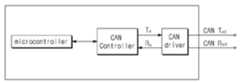
도 3은 도 1에 도시한 본 발명에 따르는 마스터 ECU(220)와 세컨드 ECU(230)에 내장된 캔통신 모듈(C)을 보여주는 블록도이다.3 is a block diagram illustrating a can communication module C embedded in the
도 3에 도시한 캔통신 모듈(C)의 동작을 설명하면 다음과 같다.Referring to the operation of the can communication module (C) shown in Figure 3 as follows.
우선 CAN Driver는CAN H, CAN L 신호를 차동제어하고, Rx를 통해 마이크로컨트롤러로 전달하고, Tx를 통해 받은 전송신호를 CAN H, CAN L 로 전달한다. 그리고 CAN Controller는 식별자(ID)를 비교하여 메시지 내용을 분석하고 우선순위를 결정한다. 또한, Data 영역(Field)의 데이터를 기억하여 데이터 분석을 위해 마이크로컨트롤러로 전송한다. 또한, 마이크로컨트롤러의 전송신호를 Tx를 통해 CAN 드라이버로 전송한다.First, the CAN driver differentially controls the CAN H and CAN L signals, transmits them to the microcontroller through Rx, and transmits the transmission signals received through Tx to CAN H and CAN L. CAN Controller then compares the identifier (ID) to analyze and prioritize message content. In addition, data of the data field (Field) is stored and transmitted to the microcontroller for data analysis. In addition, the microcontroller transmits the transmission signal to the CAN driver through Tx.
도 4는 본 발명의 일 실시 예에 따르는 마스터 ECU(220)를 자세하게 보여주기 위한 블록도이다.4 is a block diagram showing in detail a
도 4를 참조하면 본 발명에 따르는 마스터 ECU(220)는 제1 송신부(221)를 통해 제1 고장진단 메시지를 복수의 ECU(210)로 일괄 송신하고, 제1 수신부(221)를 통해 복수의 ECU(210)에서 송신한 제1 응답 메시지를 일괄 수신받는다.Referring to FIG. 4, the
이때 제1 제어부(224)는 복수의 ECU(210)중 어느 하나가 고장이라는 제1 응답 메시지로 해당 ECU를 판별하여 제1 경고부(223)를 통해 사용자에게 고장정보를 경보한다.At this time, the first control unit 224 determines the corresponding ECU by the first response message indicating that any one of the plurality of
바람직하게 제1 경고부(223)는 제1 제어부(224)가 제공하는 경보정보를 전기적으로 연결된 스피커와 디스플레이로 출력하여 사용자가 고장정보를 인지할 수 있도록 한다.Preferably, the first warning unit 223 outputs the alarm information provided by the first control unit 224 to the speaker and the display which are electrically connected so that the user can recognize the failure information.
한편, 제1 송신부(221)는 제1 고장진단 메시지를 세컨드 ECU(230)로도 송신한다. 따라서 세컨드 ECU(230)의 제1 응답 메시지에 따라 세컨드 ECU(230)의 고장정보도 함께 판별할 수 있다.Meanwhile, the
만약 캔통신 모듈(C)을 통해 수신되는 제1 응답 메시지가 기 설정된 시간을 초과해도 수신되지 않거나 비정상적인 제1 응답 메시지가 수신되는 경우, 세컨드 ECU(23)가 고장이라는 정보를 제1 경고부(223)를 통해 사용자에게 제공한다.If the first response message received through the can communication module C is not received even when the preset time exceeds a predetermined time or an abnormal first response message is received, the second ECU 23 informs that the first ECU 23 has failed. 223 to the user.
도 5는 본 발명의 일 실시 예에 따르는 세컨드 ECU(230)를 보여주기 위한 블록도이다.5 is a block diagram illustrating a
도 5를 참조하면 본 발명에 따르는 세컨드 ECU(230)는 운전자가 시동을 건 후, 기 설정된 시간 내에 마스터 ECU(220)로부터 제1 고장진단 메시지를 수신하지 못하면, 제2 송신부(231)를 통해 제2 고장진단 메시지를 마스터 ECU(220)로 송신하고, 제2 수신부(232)를 통해 마스터 ECU(220)에서 송신한 제2 응답 메시지를 수신받는다.Referring to FIG. 5, if the
이때 제2 제어부(234)는 마스터 ECU(220)로부터 기 설정된 시간이 초과해도 제2 응답 메시지를 수신받지 못하거나, 비정상적인 제2 응답 메시지를 수신하는 경우 마스터 ECU(220)가 고장이라고 판단한다.In this case, the
여기서 세컨드 ECU(230)와 마스터 ECU(220)는 각각에 내장된 캔통신 모듈(C)로 통신하기 때문에 통신 가능한 동일한 캔 프로토콜을 사용한다.Since the
한편, 세컨드 ECU(230)는 마스터 ECU(220)의 동작이 비정상인 경우, 마스터 ECU(220)의 역할을 대행한다.Meanwhile, when the operation of the
즉, 제2 제어부(234)는 제1 송신부(221)를 통해 제1 고장진단 메시지를 복수의 ECU(210)로 일괄 송신하고, 제1 수신부(222)를 통해 복수의 ECU(210)에서 송신한 제1 응답 메시지를 일괄 수신받는다.That is, the
이때 제2 제어부(234)는 복수의 ECU(210)중 어느 하나가 고장이라는 제1 응답 메시지로 해당 ECU를 판별하여 제2 경고부(233)를 통해 사용자에게 고장정보를 경보한다.In this case, the
바람직하게 제2 경고부(233)는 제2 제어부(234)가 제공하는 경보정보를 전기적으로 연결된 스피커와 디스플레이로 출력하여 사용자가 고장정보를 인지할 수 있도록 한다.Preferably, the second warning unit 233 outputs the alarm information provided by the
그리고 세컨드 ECU(230)에 내장된 제1 송신부(221)와 제1 수신부(222)는 마스터 ECU(230)에 내장된 제1 송신부(221)와 제1 수신부(222)와 동일한 기능과 동일한 구성을 갖는다.The
또한 제2 경고부(233)는 기 수행된 진단 결과인, 마스터 ECU(220)의 고장정보도 운전자에게 제공한다.In addition, the second warning unit 233 also provides the driver with failure information of the
도 6은 본 발명의 일 실시 예에 따르는 캔통신을 이용한 자동차 고장진단 네트워크 방법을 보여주기 위한 순서도이다.6 is a flowchart illustrating a method for diagnosing vehicle failure using a can communication according to an exemplary embodiment of the present invention.
도 6을 참조하면 본 발명에 따르는 캔통신을 이용한 자동차 고장진단 네트워크 방법(600)은, 운전자가 자동차에 시동을 걸면 세컨드 ECU(230)는 기 설정된 시간 이내에 마스터 ECU(220)로부터 제1 고장진단 메시지가 수신되는지 판단한다(S605).Referring to FIG. 6, the
만약 제1 고장진단 메시지가 수신되면 세컨드 ECU(230)는 제1 응답 메시지를 마스터 ECU(220)로 송신한다(S610).If the first failure diagnosis message is received, the
이와 같이 세컨드 ECU(230)가 기 설정된 시간 이내에 제1 고장진단 메시지를 수신받으면 마스터 ECU(220)가 정상동작하고 있다고 판단한다.As such, when the
그러나 마스터 ECU(220)로부터 제1 고장진단 메시지가 수신되지 않으면, 세컨드 ECU(230)는 마스터 ECU(220)로 제2 고장진단 메시지를 송신한다(S615).However, if the first failure diagnosis message is not received from the
마스터 ECU(220)는 수신된 제2 고장진단 메시지에 대한 제2 응답 메시지를 송신하고, 제2 응답 메시지가 세컨드 ECU로 정상 수신되면(S620), 마스터 ECU는 다음과 같이 정상 동작한다.The
즉, 마스터 ECU(220)는 세컨드 ECU 및 복수의 ECU로 제1 고장진단 메시지를 일괄 송신한다(S625).That is, the
그 후, 마스터 ECU(220)는 송신된 제1 고장진단 메시지에 대한 제1 응답 메시지를 세컨드 ECU 및 복수의 ECU로부터 일괄 수신받는다(S630).Thereafter, the
마지막으로 세컨드 ECU 및 복수의 ECU의 응답 메시지에 따른 검사결과를 운전자에게 제공 한다(S635).Finally, the inspection result according to the response message of the second ECU and the plurality of ECUs is provided to the driver (S635).
이 때 운전자는 자동차 내에 구비된 스피커나 디스플레이를 통해 고장이 발생한 ECU를 확인할 수 있기 때문에 고장으로 인한 교통사고를 미리 예방할 수 있다.At this time, the driver can check the ECU that has failed through the speaker or display provided in the vehicle, thereby preventing traffic accidents caused by the failure in advance.
반면에, 세컨드 ECU(230)가 마스터 ECU(220)로 송신한 제2 고장진단 메시지에 대한 제2 응답 메시지를 수신받지 못하거나, 비정상적인 제2 응답 메시지를 수신하면(S620), 세컨드 ECU(230)는 마스터 ECU(220)가 고장이라고 판단하여 다음과 같은 절차를 수행하여 마스터 ECU(220)의 역할을 대행한다.On the other hand, when the
우선, 세컨드 ECU(230)는 복수의 ECU로 제1 고장진단 메시지를 일괄 송신하고(S640), 세컨드 ECU(230)가 송신한 제1 고장 메시지에 대한 제1 응답 메시지를 복수의 ECU로부터 수신받는다(S645).First, the
그 후, 세컨드 ECU(230)는 제1 응답 메시지에 따라 복수의 ECU의 검사결과를 사용자에게 제공한다(S650).Thereafter, the
이 경우, 세컨드 ECU는 마스터 ECU의 고장정보 및 확인된 고장 ECU 정보를 사용자가 인지할 수 있도록 경보할 수 있다.In this case, the second ECU may alert the user to the fault information of the master ECU and the confirmed fault ECU information.
이상과 같이 본 발명은 비록 한정된 실시 예와 도면에 의해 설명되었으나, 본 발명은 상기의 실시 예에 한정되는 것은 아니며, 본 발명이 속하는 분야에서 통상의 지식을 가진 자라면 이러한 기재로부터 다양한 수정 및 변형이 가능하다.While the invention has been shown and described with reference to certain preferred embodiments thereof, it will be understood by those of ordinary skill in the art that various changes in form and details may be made therein without departing from the spirit and scope of the invention as defined by the appended claims. This is possible.
그러므로 본 발명의 범위는 설명된 실시 예에 국한되어 정해져서는 아니 되며, 후술하는 특허청구범위뿐만 아니라 특허청구범위와 균등한 것들에 의해 정해져야 한다.Therefore, the scope of the present invention should not be limited by the described embodiments, but should be determined by the scope of the appended claims as well as the appended claims.
210: 복수의 ECU 220: 마스터 ECU
230: 세컨드 ECU C: 캔통신모듈210: multiple ECU 220: master ECU
230: second ECU C: can communication module
Claims (8)
Translated fromKorean상기 자동차 운전자가 시동을 걸면, 복수의 전자제어유니트(Electric Control Unit, ECU)로 제1 고장진단 메시지를 일괄 송신하여, 상기 제1 고장진단 메시지에 대한 제1 응답 메시지를 일괄 수신받는 마스터 ECU; 및
상기 시동을 건 후, 기 설정된 시간 내에 상기 마스터 ECU로부터 상기 제1 고장진단 메시지를 수신받지 못하면, 상기 마스터 ECU로 제2 고장진단 메시지를 송신하고, 상기 제2 고장진단 메시지에 대한 제2 응답 메시지가 기 설정된 시간 동안 수신되지 않거나 비정상적으로 수신되는 경우, 경고신호를 발생시키고, 상기 복수의 ECU로 상기 제1 고장진단 메시지를 일괄 송신하여, 상기 제1 고장진단 메시지에 대한 상기 제1 응답 메시지를 일괄 수신받는 세컨드 ECU를 포함하는 것을 특징으로 하는 캔통신을 이용한 자동차 고장진단 네트워크 시스템.In the car diagnosis network system,
A master ECU which collectively transmits a first failure diagnosis message to a plurality of electric control units (ECUs) when the vehicle driver starts, and receives the first response message in response to the first failure diagnosis message; And
If the first failure diagnosis message is not received from the master ECU within a preset time after the start-up, a second failure diagnosis message is transmitted to the master ECU, and a second response message to the second failure diagnosis message is received. When not received for a predetermined time or abnormally received, a warning signal is generated, the first failure diagnosis message is collectively transmitted to the plurality of ECUs, and the first response message to the first failure diagnosis message is received. A vehicle fault diagnosis network system using can communication, comprising a second ECU receiving a batch.
상기 마스터 ECU와 캔(Controller Area Network, CAN) 통신을 하는 것을 특징으로 하는 캔통신을 이용한 자동차 고장진단 네트워크 시스템.The method of claim 1, wherein the second ECU
Car failure diagnosis network system using the can communication, characterized in that the CAN (Controller Area Network, CAN) communication with the master ECU.
상기 경고신호를 사용자가 인지하도록 출력하는 상기 마스터 ECU 및 상기 세컨드 ECU와 전기적으로 연결된 스피커와 디스플레이를 더 포함하는 것을 특징으로 하는 캔통신을 이용한 자동차 고장진단 네트워크 시스템.According to claim 1, The vehicle fault diagnosis network system using can communication
And a speaker and a display electrically connected to the master ECU and the second ECU for outputting the warning signal to the user.
사용자가 시동을 걸면, 세컨드 전자제어유니트(Electric Control Unit, ECU)가 기 설정된 시간 내에 마스터 ECU로부터 제1 고장진단 메시지를 수신하는지 확인하는 단계;
상기 마스터 ECU로부터 상기 제1 고장진단 메시지가 수신되지 않거나 비정상적으로 수신되면, 상기 세컨드 ECU가 상기 마스터 ECU로 제2 고장진단 메시지를 송신하는 단계;
상기 세컨드 ECU가 상기 마스터 ECU로 송신한 상기 제2 고장진단 메시지에 대한 제2 응답 메시지를 정상 수신하는 단계;
상기 마스터 ECU가 세컨드 ECU 및 복수의 ECU로 제1 고장진단 메시지를 일괄 송신하는 단계; 및
상기 마스터 ECU가 상기 제1 고장진단 메시지에 대한 제1 응답 메시지를 상기 세컨드 ECU 및 상기 복수의 ECU로부터 일괄 수신받는 단계를 포함하는 것을 특징으로 하는 캔통신을 이용한 자동차 고장진단 네트워크 방법.In the vehicle fault diagnosis network method,
When the user starts up, confirming whether the second electric control unit (ECU) receives the first failure diagnosis message from the master ECU within a preset time;
If the first troubleshooting message is not received or abnormally received from the master ECU, sending a second troubleshooting message to the master ECU by the second ECU;
Receiving, by the second ECU, a second response message to the second failure diagnosis message normally transmitted to the master ECU;
The master ECU collectively transmitting a first failure diagnosis message to a second ECU and a plurality of ECUs; And
And receiving, by the master ECU, a first response message for the first failure diagnosis message from the second ECU and the plurality of ECUs.
상기 제2 고장진단 메시지에 대한 응답 메시지가 수신되지 않거나 비정상적으로 수신되면,
상기 세컨드 ECU가, 상기 복수의 ECU로 제1 고장진단 메시지를 일괄 송신하는 단계
상기 세컨드 ECU가 송신한 상기 제1 고장진단 메시지에 대한 제1 응답 메시지를 상기 복수의 ECU로부터 수신받는 단계 및
상기 제1 응답 메시지에 따른 복수의 ECU 검사 결과정보와, 상기 마스터 ECU의 고장정보를 사용자에게 제공하는 단계를 더 포함하는 것을 특징으로 하는 캔통신을 이용한 자동차 고장진단 네트워크 방법.5. The method of claim 4, wherein transmitting the second troubleshooting message
If a response message to the second troubleshooting message is not received or is abnormally received,
The second ECU collectively transmitting a first failure diagnosis message to the plurality of ECUs
Receiving a first response message for the first failure diagnosis message transmitted by the second ECU from the plurality of ECUs;
And providing the plurality of ECU test result information and the failure information of the master ECU to the user according to the first response message.
상기 세컨드 ECU 및 상기 복수의 ECU의 응답 메시지에 따른 검사결과를 운전자에게 제공하는 단계를 더 포함하는 것을 특징으로 하는 캔통신을 이용한 자동차 고장진단 네트워크 방법.5. The method of claim 4, wherein the master ECU receives the first response message for the first failure diagnosis message from the second ECU and the plurality of ECUs.
And providing the driver with a test result according to the response message of the second ECU and the plurality of ECUs.
상기 마스터 ECU와 캔(Controller Area Network, CAN) 통신을 하는 것을 특징으로 하는 캔통신을 이용한 자동차 고장진단 네트워크 방법.The method of claim 4, wherein the second ECU is
Car failure diagnosis network method using the can communication, characterized in that the CAN (Controller Area Network, CAN) communication with the master ECU.
고장이 발생한 ECU에 대한 경고신호를 사용자가 인지하도록 상기 마스터 ECU 및 상기 세컨드 ECU와 전기적으로 연결된 스피커를 통해 출력하거나, 고장이 발생한 상기 마스터 ECU와 해당 ECU의 정보를 디스플레이하는 것을 특징으로 하는 캔통신을 이용한 자동차 고장진단 네트워크 방법.The method of claim 5, wherein the failure information
Can communication, characterized by outputting through a speaker electrically connected to the master ECU and the second ECU so as to recognize a warning signal for the ECU having a failure, or displaying the information of the master ECU and the ECU with the failure occurs Automotive fault diagnosis network method using
Priority Applications (1)
| Application Number | Priority Date | Filing Date | Title |
|---|---|---|---|
| KR1020110132176AKR101297024B1 (en) | 2011-12-09 | 2011-12-09 | Method and apparatus for fault diagnosis network of car using can communication |
Applications Claiming Priority (1)
| Application Number | Priority Date | Filing Date | Title |
|---|---|---|---|
| KR1020110132176AKR101297024B1 (en) | 2011-12-09 | 2011-12-09 | Method and apparatus for fault diagnosis network of car using can communication |
Publications (2)
| Publication Number | Publication Date |
|---|---|
| KR20130065353A KR20130065353A (en) | 2013-06-19 |
| KR101297024B1true KR101297024B1 (en) | 2013-08-14 |
Family
ID=48861986
Family Applications (1)
| Application Number | Title | Priority Date | Filing Date |
|---|---|---|---|
| KR1020110132176AActiveKR101297024B1 (en) | 2011-12-09 | 2011-12-09 | Method and apparatus for fault diagnosis network of car using can communication |
Country Status (1)
| Country | Link |
|---|---|
| KR (1) | KR101297024B1 (en) |
Cited By (2)
| Publication number | Priority date | Publication date | Assignee | Title |
|---|---|---|---|---|
| CN105700510A (en)* | 2014-12-09 | 2016-06-22 | 现代奥特劳恩株式会社 | Error variance detection method of CAN communication system and the CAN communication system |
| CN105818783A (en)* | 2015-01-28 | 2016-08-03 | 通用汽车环球科技运作有限责任公司 | Responding to electronic in-vehicle intrusions |
Families Citing this family (3)
| Publication number | Priority date | Publication date | Assignee | Title |
|---|---|---|---|---|
| KR102683789B1 (en)* | 2018-08-31 | 2024-07-10 | 현대자동차주식회사 | System and method for checking fault of can communication |
| KR102596471B1 (en)* | 2018-09-18 | 2023-11-02 | 한국전력공사 | Method for diagnosing and maintenancing of vehicle condition during electric vehicle charging |
| KR102637909B1 (en)* | 2019-01-23 | 2024-02-19 | 에이치엘만도 주식회사 | Redundancy circuit for electric power steering system |
Citations (3)
| Publication number | Priority date | Publication date | Assignee | Title |
|---|---|---|---|---|
| JP2002158668A (en)* | 2000-11-17 | 2002-05-31 | Denso Corp | Abnormality detector of network system for vehicle |
| JP2003256033A (en)* | 2002-02-28 | 2003-09-10 | Denso Corp | Vehicular communication system |
| KR20090000008A (en)* | 2006-12-14 | 2009-01-07 | 현대자동차주식회사 | Collision avoidance system and method for diagnosis terminal period in vehicle diagnosis |
- 2011
- 2011-12-09KRKR1020110132176Apatent/KR101297024B1/enactiveActive
Patent Citations (3)
| Publication number | Priority date | Publication date | Assignee | Title |
|---|---|---|---|---|
| JP2002158668A (en)* | 2000-11-17 | 2002-05-31 | Denso Corp | Abnormality detector of network system for vehicle |
| JP2003256033A (en)* | 2002-02-28 | 2003-09-10 | Denso Corp | Vehicular communication system |
| KR20090000008A (en)* | 2006-12-14 | 2009-01-07 | 현대자동차주식회사 | Collision avoidance system and method for diagnosis terminal period in vehicle diagnosis |
Cited By (4)
| Publication number | Priority date | Publication date | Assignee | Title |
|---|---|---|---|---|
| CN105700510A (en)* | 2014-12-09 | 2016-06-22 | 现代奥特劳恩株式会社 | Error variance detection method of CAN communication system and the CAN communication system |
| CN105700510B (en)* | 2014-12-09 | 2018-04-03 | 现代奥特劳恩株式会社 | The disperse errors detection method and CAN communication system of CAN communication system |
| US9947144B2 (en) | 2014-12-09 | 2018-04-17 | Hyundai Autron Co., Ltd. | Error variance detection method of CAN communication system and the CAN communication system |
| CN105818783A (en)* | 2015-01-28 | 2016-08-03 | 通用汽车环球科技运作有限责任公司 | Responding to electronic in-vehicle intrusions |
Also Published As
| Publication number | Publication date |
|---|---|
| KR20130065353A (en) | 2013-06-19 |
Similar Documents
| Publication | Publication Date | Title |
|---|---|---|
| US10670663B2 (en) | Warning method for a high-voltage battery of a motor vehicle in the case of an accident of the motor vehicle, a warning system for carrying out the warning method, and a motor vehicle that comprises components of the warning system | |
| EP3694738B1 (en) | Alternative display options for vehicle telltales | |
| US7889072B2 (en) | Failure information detection device, failure information detection system, server, and failure information detection method | |
| KR101297024B1 (en) | Method and apparatus for fault diagnosis network of car using can communication | |
| CN103810879A (en) | On-vehicle information service system and method for providing on-vehicle information service in the system | |
| CN111275920A (en) | Vehicle, user communication terminal and collision accident detection processing method | |
| KR20120129053A (en) | System and method for diagnosing vehicle using wireless network | |
| CN110949318A (en) | Vehicle anti-theft method and T-box with anti-theft function | |
| KR100205974B1 (en) | Remoute car management device and control method | |
| JP6191397B2 (en) | Communication relay device, communication relay processing | |
| JP4107238B2 (en) | Vehicle communication system | |
| KR20080036296A (en) | Method and device for preventing can ID collision in vehicle diagnostic device | |
| KR102201646B1 (en) | Apparatus and method for processing information of a vehicle for accident notification | |
| CN102350952B (en) | Automobile air bag restraint system monitoring system, air bag restraint system monitoring method and automobile | |
| KR101145556B1 (en) | examining system of car using wireless communication network and method thereof | |
| JP2004350137A (en) | Vehicle communication system | |
| KR100980973B1 (en) | Vehicle failure diagnosis system and method using wireless communication | |
| KR101053722B1 (en) | Automotive self-diagnosis system using telematics device and method | |
| KR101869512B1 (en) | Service Terminal Capable of Informing Car Accident through LPWAN Network and Method thereof | |
| JP2002316598A (en) | Data communication backup system | |
| KR100374153B1 (en) | System and method to diagnose and control condition car using telemetering system | |
| KR100499944B1 (en) | self diagnosis system for automobile using telematics apparatus | |
| KR20040011230A (en) | auto diagnosis system for automobile using telematics apparatus | |
| KR100499945B1 (en) | self diagnosis system for automobile | |
| KR200214343Y1 (en) | System to diagnose and control condition car using telemetering system |
Legal Events
| Date | Code | Title | Description |
|---|---|---|---|
| A201 | Request for examination | ||
| PA0109 | Patent application | Patent event code:PA01091R01D Comment text:Patent Application Patent event date:20111209 | |
| PA0201 | Request for examination | ||
| E902 | Notification of reason for refusal | ||
| PE0902 | Notice of grounds for rejection | Comment text:Notification of reason for refusal Patent event date:20121127 Patent event code:PE09021S01D | |
| E902 | Notification of reason for refusal | ||
| PE0902 | Notice of grounds for rejection | Comment text:Notification of reason for refusal Patent event date:20130513 Patent event code:PE09021S01D | |
| PG1501 | Laying open of application | ||
| E701 | Decision to grant or registration of patent right | ||
| PE0701 | Decision of registration | Patent event code:PE07011S01D Comment text:Decision to Grant Registration Patent event date:20130802 | |
| GRNT | Written decision to grant | ||
| PR0701 | Registration of establishment | Comment text:Registration of Establishment Patent event date:20130808 Patent event code:PR07011E01D | |
| PR1002 | Payment of registration fee | Payment date:20130808 End annual number:3 Start annual number:1 | |
| PG1601 | Publication of registration | ||
| FPAY | Annual fee payment | Payment date:20160809 Year of fee payment:6 | |
| PR1001 | Payment of annual fee | Payment date:20160809 Start annual number:4 End annual number:6 | |
| FPAY | Annual fee payment | Payment date:20190701 Year of fee payment:9 | |
| PR1001 | Payment of annual fee | Payment date:20190701 Start annual number:7 End annual number:9 | |
| PR1001 | Payment of annual fee | Payment date:20250625 Start annual number:13 End annual number:15 |