KR101296317B1 - Chemical vapor deposition system - Google Patents
Chemical vapor deposition systemDownload PDFInfo
- Publication number
- KR101296317B1 KR101296317B1KR1020107018869AKR20107018869AKR101296317B1KR 101296317 B1KR101296317 B1KR 101296317B1KR 1020107018869 AKR1020107018869 AKR 1020107018869AKR 20107018869 AKR20107018869 AKR 20107018869AKR 101296317 B1KR101296317 B1KR 101296317B1
- Authority
- KR
- South Korea
- Prior art keywords
- substrates
- processing apparatus
- substrate processing
- pedestal
- radiant heat
- Prior art date
- Legal status (The legal status is an assumption and is not a legal conclusion. Google has not performed a legal analysis and makes no representation as to the accuracy of the status listed.)
- Active
Links
Images


Classifications
- C—CHEMISTRY; METALLURGY
- C23—COATING METALLIC MATERIAL; COATING MATERIAL WITH METALLIC MATERIAL; CHEMICAL SURFACE TREATMENT; DIFFUSION TREATMENT OF METALLIC MATERIAL; COATING BY VACUUM EVAPORATION, BY SPUTTERING, BY ION IMPLANTATION OR BY CHEMICAL VAPOUR DEPOSITION, IN GENERAL; INHIBITING CORROSION OF METALLIC MATERIAL OR INCRUSTATION IN GENERAL
- C23C—COATING METALLIC MATERIAL; COATING MATERIAL WITH METALLIC MATERIAL; SURFACE TREATMENT OF METALLIC MATERIAL BY DIFFUSION INTO THE SURFACE, BY CHEMICAL CONVERSION OR SUBSTITUTION; COATING BY VACUUM EVAPORATION, BY SPUTTERING, BY ION IMPLANTATION OR BY CHEMICAL VAPOUR DEPOSITION, IN GENERAL
- C23C16/00—Chemical coating by decomposition of gaseous compounds, without leaving reaction products of surface material in the coating, i.e. chemical vapour deposition [CVD] processes
- C23C16/44—Chemical coating by decomposition of gaseous compounds, without leaving reaction products of surface material in the coating, i.e. chemical vapour deposition [CVD] processes characterised by the method of coating
- C23C16/448—Chemical coating by decomposition of gaseous compounds, without leaving reaction products of surface material in the coating, i.e. chemical vapour deposition [CVD] processes characterised by the method of coating characterised by the method used for generating reactive gas streams, e.g. by evaporation or sublimation of precursor materials
- C23C16/452—Chemical coating by decomposition of gaseous compounds, without leaving reaction products of surface material in the coating, i.e. chemical vapour deposition [CVD] processes characterised by the method of coating characterised by the method used for generating reactive gas streams, e.g. by evaporation or sublimation of precursor materials by activating reactive gas streams before their introduction into the reaction chamber, e.g. by ionisation or addition of reactive species
- C—CHEMISTRY; METALLURGY
- C23—COATING METALLIC MATERIAL; COATING MATERIAL WITH METALLIC MATERIAL; CHEMICAL SURFACE TREATMENT; DIFFUSION TREATMENT OF METALLIC MATERIAL; COATING BY VACUUM EVAPORATION, BY SPUTTERING, BY ION IMPLANTATION OR BY CHEMICAL VAPOUR DEPOSITION, IN GENERAL; INHIBITING CORROSION OF METALLIC MATERIAL OR INCRUSTATION IN GENERAL
- C23C—COATING METALLIC MATERIAL; COATING MATERIAL WITH METALLIC MATERIAL; SURFACE TREATMENT OF METALLIC MATERIAL BY DIFFUSION INTO THE SURFACE, BY CHEMICAL CONVERSION OR SUBSTITUTION; COATING BY VACUUM EVAPORATION, BY SPUTTERING, BY ION IMPLANTATION OR BY CHEMICAL VAPOUR DEPOSITION, IN GENERAL
- C23C16/00—Chemical coating by decomposition of gaseous compounds, without leaving reaction products of surface material in the coating, i.e. chemical vapour deposition [CVD] processes
- C23C16/44—Chemical coating by decomposition of gaseous compounds, without leaving reaction products of surface material in the coating, i.e. chemical vapour deposition [CVD] processes characterised by the method of coating
- C23C16/48—Chemical coating by decomposition of gaseous compounds, without leaving reaction products of surface material in the coating, i.e. chemical vapour deposition [CVD] processes characterised by the method of coating by irradiation, e.g. photolysis, radiolysis, particle radiation
- C23C16/481—Chemical coating by decomposition of gaseous compounds, without leaving reaction products of surface material in the coating, i.e. chemical vapour deposition [CVD] processes characterised by the method of coating by irradiation, e.g. photolysis, radiolysis, particle radiation by radiant heating of the substrate
- C—CHEMISTRY; METALLURGY
- C23—COATING METALLIC MATERIAL; COATING MATERIAL WITH METALLIC MATERIAL; CHEMICAL SURFACE TREATMENT; DIFFUSION TREATMENT OF METALLIC MATERIAL; COATING BY VACUUM EVAPORATION, BY SPUTTERING, BY ION IMPLANTATION OR BY CHEMICAL VAPOUR DEPOSITION, IN GENERAL; INHIBITING CORROSION OF METALLIC MATERIAL OR INCRUSTATION IN GENERAL
- C23C—COATING METALLIC MATERIAL; COATING MATERIAL WITH METALLIC MATERIAL; SURFACE TREATMENT OF METALLIC MATERIAL BY DIFFUSION INTO THE SURFACE, BY CHEMICAL CONVERSION OR SUBSTITUTION; COATING BY VACUUM EVAPORATION, BY SPUTTERING, BY ION IMPLANTATION OR BY CHEMICAL VAPOUR DEPOSITION, IN GENERAL
- C23C16/00—Chemical coating by decomposition of gaseous compounds, without leaving reaction products of surface material in the coating, i.e. chemical vapour deposition [CVD] processes
- C23C16/44—Chemical coating by decomposition of gaseous compounds, without leaving reaction products of surface material in the coating, i.e. chemical vapour deposition [CVD] processes characterised by the method of coating
- C23C16/52—Controlling or regulating the coating process
- H—ELECTRICITY
- H01—ELECTRIC ELEMENTS
- H01L—SEMICONDUCTOR DEVICES NOT COVERED BY CLASS H10
- H01L21/00—Processes or apparatus adapted for the manufacture or treatment of semiconductor or solid state devices or of parts thereof
- H01L21/67—Apparatus specially adapted for handling semiconductor or electric solid state devices during manufacture or treatment thereof; Apparatus specially adapted for handling wafers during manufacture or treatment of semiconductor or electric solid state devices or components ; Apparatus not specifically provided for elsewhere
- H01L21/67005—Apparatus not specifically provided for elsewhere
- H01L21/67242—Apparatus for monitoring, sorting or marking
- H01L21/67248—Temperature monitoring
- H—ELECTRICITY
- H01—ELECTRIC ELEMENTS
- H01L—SEMICONDUCTOR DEVICES NOT COVERED BY CLASS H10
- H01L21/00—Processes or apparatus adapted for the manufacture or treatment of semiconductor or solid state devices or of parts thereof
- H01L21/67—Apparatus specially adapted for handling semiconductor or electric solid state devices during manufacture or treatment thereof; Apparatus specially adapted for handling wafers during manufacture or treatment of semiconductor or electric solid state devices or components ; Apparatus not specifically provided for elsewhere
- H01L21/683—Apparatus specially adapted for handling semiconductor or electric solid state devices during manufacture or treatment thereof; Apparatus specially adapted for handling wafers during manufacture or treatment of semiconductor or electric solid state devices or components ; Apparatus not specifically provided for elsewhere for supporting or gripping
- H01L21/687—Apparatus specially adapted for handling semiconductor or electric solid state devices during manufacture or treatment thereof; Apparatus specially adapted for handling wafers during manufacture or treatment of semiconductor or electric solid state devices or components ; Apparatus not specifically provided for elsewhere for supporting or gripping using mechanical means, e.g. chucks, clamps or pinches
- H01L21/68714—Apparatus specially adapted for handling semiconductor or electric solid state devices during manufacture or treatment thereof; Apparatus specially adapted for handling wafers during manufacture or treatment of semiconductor or electric solid state devices or components ; Apparatus not specifically provided for elsewhere for supporting or gripping using mechanical means, e.g. chucks, clamps or pinches the wafers being placed on a susceptor, stage or support
- H01L21/68764—Apparatus specially adapted for handling semiconductor or electric solid state devices during manufacture or treatment thereof; Apparatus specially adapted for handling wafers during manufacture or treatment of semiconductor or electric solid state devices or components ; Apparatus not specifically provided for elsewhere for supporting or gripping using mechanical means, e.g. chucks, clamps or pinches the wafers being placed on a susceptor, stage or support characterised by a movable susceptor, stage or support, others than those only rotating on their own vertical axis, e.g. susceptors on a rotating caroussel
- H—ELECTRICITY
- H01—ELECTRIC ELEMENTS
- H01L—SEMICONDUCTOR DEVICES NOT COVERED BY CLASS H10
- H01L21/00—Processes or apparatus adapted for the manufacture or treatment of semiconductor or solid state devices or of parts thereof
- H01L21/67—Apparatus specially adapted for handling semiconductor or electric solid state devices during manufacture or treatment thereof; Apparatus specially adapted for handling wafers during manufacture or treatment of semiconductor or electric solid state devices or components ; Apparatus not specifically provided for elsewhere
- H01L21/683—Apparatus specially adapted for handling semiconductor or electric solid state devices during manufacture or treatment thereof; Apparatus specially adapted for handling wafers during manufacture or treatment of semiconductor or electric solid state devices or components ; Apparatus not specifically provided for elsewhere for supporting or gripping
- H01L21/687—Apparatus specially adapted for handling semiconductor or electric solid state devices during manufacture or treatment thereof; Apparatus specially adapted for handling wafers during manufacture or treatment of semiconductor or electric solid state devices or components ; Apparatus not specifically provided for elsewhere for supporting or gripping using mechanical means, e.g. chucks, clamps or pinches
- H01L21/68714—Apparatus specially adapted for handling semiconductor or electric solid state devices during manufacture or treatment thereof; Apparatus specially adapted for handling wafers during manufacture or treatment of semiconductor or electric solid state devices or components ; Apparatus not specifically provided for elsewhere for supporting or gripping using mechanical means, e.g. chucks, clamps or pinches the wafers being placed on a susceptor, stage or support
- H01L21/68771—Apparatus specially adapted for handling semiconductor or electric solid state devices during manufacture or treatment thereof; Apparatus specially adapted for handling wafers during manufacture or treatment of semiconductor or electric solid state devices or components ; Apparatus not specifically provided for elsewhere for supporting or gripping using mechanical means, e.g. chucks, clamps or pinches the wafers being placed on a susceptor, stage or support characterised by supporting more than one semiconductor substrate
Landscapes
- Chemical & Material Sciences (AREA)
- Engineering & Computer Science (AREA)
- Physics & Mathematics (AREA)
- Manufacturing & Machinery (AREA)
- Materials Engineering (AREA)
- Mechanical Engineering (AREA)
- Metallurgy (AREA)
- Organic Chemistry (AREA)
- General Chemical & Material Sciences (AREA)
- Condensed Matter Physics & Semiconductors (AREA)
- General Physics & Mathematics (AREA)
- Chemical Kinetics & Catalysis (AREA)
- Computer Hardware Design (AREA)
- Microelectronics & Electronic Packaging (AREA)
- Power Engineering (AREA)
- Health & Medical Sciences (AREA)
- Toxicology (AREA)
- Chemical Vapour Deposition (AREA)
- Drying Of Semiconductors (AREA)
Abstract
Translated fromKoreanDescription
Translated fromKorean본원 발명의 실시예는 개략적으로 기판 상에서 화학기상증착(CVD)을 하기 위한 장치 및 방법에 관한 것이며, 특히 화학기상증착에서 사용하기 위한 프로세스 챔버와 관련된 것이다.Embodiments of the present invention relate generally to apparatus and methods for chemical vapor deposition (CVD) on a substrate, and in particular to a process chamber for use in chemical vapor deposition.
그룹 Ⅲ-Ⅴ 필름은 단파장 발광 다이오드(LED), 레이저 다이오드(LD), 및 고전력, 고주파, 고온 트랜지스터 및 집적회로를 포함하는 전자 소자와 같은 다양한 반도체 소자의 개발 및 제조에 있어서 그 중요성이 커지고 있다. 예를 들어, 단파장(예를 들어, 청색/녹색으로부터 자외선까지) LED가 그룹 Ⅲ-질화물 반도체 물질 갈륨 질화물(GaN)을 이용하여 제조된다. GaN을 이용하여 제조된 단파장 LED는 그룹 Ⅱ-Ⅵ 원소를 포함하는 비-질화물 반도체 물질을 이용하여 제조된 단파장 LED에 비해서 상당히 높아진 효율 및 상당히 길어진 작동 수명을 제공할 수 있다는 것이 관찰되었다.Group III-V films are becoming increasingly important in the development and manufacture of various semiconductor devices such as short wavelength light emitting diodes (LEDs), laser diodes (LDs), and electronic devices including high power, high frequency, high temperature transistors, and integrated circuits. . For example, short wavelength (eg, blue / green to ultraviolet) LEDs are fabricated using group III-nitride semiconductor material gallium nitride (GaN). It has been observed that short wavelength LEDs fabricated using GaN can provide significantly higher efficiency and significantly longer operating life compared to short wavelength LEDs fabricated using non-nitride semiconductor materials containing group II-VI elements.
GaN과 같은 그룹 Ⅲ-질화물을 증착하기 위해서 이용되는 하나의 방법은 금속 유기 화학기상증착(MOCVD)이다. 일반적으로, 이러한 화학기상증착 방법은 갈륨(Ga)과 같은 하나 이상의 그룹 Ⅲ 원소를 포함하는 제 1 전구체 가스의 안정성을 보장하기 위해서 온도가 제어된 분위기를 제공하는 반응기 내에서 실시된다. 암모니아(NH3)와 같은 제 2 전구체 가스는 그룹 Ⅲ-질화물을 형성하는데 필요한 질소를 제공한다. 2개의 전구체 가스가 반응기 내의 프로세싱 영역으로 주입되고, 그러한 반응기 내에서 그 가스가 혼합되고 그리고 프로세싱 영역 내의 가열된 기판을 향해서 이동하게 된다. 기판을 향한 전구체 가스의 운반을 돕기 위해서 캐리어 가스가 이용될 수 있을 것이다. 전구체가 가열된 기판의 표면에서 반응하여 GaN과 같은 그룹 Ⅲ-질화물 층을 기판 표면 상에 형성한다. 필름의 품질은 부분적으로 증착 균일성에 따라 달라지며, 그러한 증착 균일성은 다시 기판에 걸친 전구체의 균일한 유동 및 혼합에 따라서 달라진다.One method used to deposit group III-nitrides, such as GaN, is metal organic chemical vapor deposition (MOCVD). In general, this chemical vapor deposition method is carried out in a reactor that provides a temperature controlled atmosphere to ensure the stability of the first precursor gas comprising one or more Group III elements such as gallium (Ga). A second precursor gas, such as ammonia (NH3 ), provides the nitrogen needed to form group III-nitrides. Two precursor gases are injected into the processing region in the reactor where they are mixed and moved towards the heated substrate in the processing region. Carrier gas may be used to assist in transporting the precursor gas towards the substrate. The precursor reacts at the surface of the heated substrate to form a group III-nitride layer such as GaN on the substrate surface. The quality of the film depends in part on the deposition uniformity, which in turn depends on the uniform flow and mixing of the precursors across the substrate.
LED, LD, 트랜지스터 및 집적 회로에 대한 수요가 증대됨에 따라, 고품질의 그룹 Ⅲ-질화물 필름을 증착하는 효율이 보다 중요해지고 있다. 그에 따라, 대형 기판 및 큰 증착 면적에 걸쳐 균일한 전구체 혼합 및 일정한 필름 품질을 제공할 수 있는 개선된 증착 장치 및 프로세스가 요구되고 있다 할 것이다.As the demand for LEDs, LDs, transistors, and integrated circuits increases, the efficiency of depositing high quality Group III-nitride films becomes more important. Accordingly, there is a need for improved deposition apparatus and processes that can provide uniform precursor mixing and consistent film quality over large substrates and large deposition areas.
개략적으로, 본원 발명은 기판 상에 화학기상증착(CVD)을 하기 위한 장치 및 방법에 관한 것이고, 특히 화학기상증착에서 사용하기 위한 프로세스 챔버 및 부품에 관한 것이다.In general, the present invention relates to apparatus and methods for chemical vapor deposition (CVD) on a substrate, and in particular to process chambers and components for use in chemical vapor deposition.
일 실시예에서, 기판 상에서 금속 유기 화학기상증착(CVD)을 하기 위한 장치가 제공된다. 그러한 프로세스 장치는 프로세스 체적부(volume)를 형성하는 챔버 본체를 포함한다. 제 1 평면 내의 샤워헤드가 프로세스 체적부의 상단 부분을 형성한다. 기판 캐리어 플레이트가 제 2 평면 내에서 프로세스 체적부를 가로질러 연장하여 샤워헤드와 받침대 플레이트 사이에서 상부 프로세스 체적부를 형성한다. 제 3 평면 내의 투명 물질이 프로세스 체적부의 바닥 부분을 형성하여 기판 캐리어 플레이트와 투명 물질 사이에 하부 프로세스 체적부를 형성한다. 복수의 램프가 투명 물질 아래쪽에 위치된 하나 또는 둘 이상의 영역을 형성한다. 상기 복수의 램프는 기판 캐리어 플레이트를 향해서 복사 열을 지향시켜 하나 또는 둘 이상의 복사 열 영역을 생성한다.In one embodiment, an apparatus for metal organic chemical vapor deposition (CVD) on a substrate is provided. Such process apparatus includes a chamber body forming a process volume. The showerhead in the first plane forms the upper portion of the process volume. The substrate carrier plate extends across the process volume in the second plane to form an upper process volume between the showerhead and the pedestal plate. Transparent material in the third plane forms the bottom portion of the process volume to form the lower process volume between the substrate carrier plate and the transparent material. The plurality of lamps form one or more regions located below the transparent material. The plurality of lamps direct radiant heat towards the substrate carrier plate to create one or more radiant heat regions.
다른 실시예에서, 금속 유기 화학기상증착을 위한 기판 프로세싱 장치가 제공된다. 그러한 프로세스 장치는 프로세스 체적부를 형성하는 챔버 본체를 포함한다. 제 1 평면 내의 샤워헤드가 프로세스 체적부의 상단 부분을 형성한다. 기판 캐리어 플레이트가 프로세스 체적부 내에서 제 1 평면 아래쪽의 제 2 평면 내에서 프로세스 체적부를 가로질러 연장한다. 각을 이루는 부분을 포함하는 광 차폐부가 기판 캐리어 플레이트의 둘레를 둘러싸며, 이때 광 차폐부가 기판 캐리어 플레이트를 향해서 복사 열을 지향시킨다.In another embodiment, a substrate processing apparatus for metal organic chemical vapor deposition is provided. Such process apparatus includes a chamber body forming a process volume. The showerhead in the first plane forms the upper portion of the process volume. The substrate carrier plate extends across the process volume in a second plane below the first plane in the process volume. A light shield comprising an angled portion surrounds the substrate carrier plate, with the light shield directing radiant heat towards the substrate carrier plate.
전술한 본원 발명의 특징이 보다 구체적으로 이해될 수 있도록 하기 위해서, 간략히 전술한 본원 발명에 대한 더욱 구체적인 설명을, 일부가 첨부 도면에 도시된 실시예를 참조하여 이하에 기재한다. 그러나, 본원 발명은 다른 균등한 실시예도 포함할 수 있으므로, 첨부 도면은 단지 본원 발명의 통상적인 실시예를 도시한 것이고 그에 따라 본원 발명의 범위를 제한하고자 하는 것이 아니라는 점을 주목하여야 할 것이다.BRIEF DESCRIPTION OF DRAWINGS To enable the above-described features of the present invention to be understood in more detail, the following briefly describes a more detailed description of the present invention with reference to the embodiments, some of which are illustrated in the accompanying drawings. It should be noted, however, that the present invention may also include other equivalent embodiments, so that the accompanying drawings are merely illustrative of typical embodiments of the invention and are not intended to limit the scope of the invention.
도 1은 본원 발명의 일 실시예에 따른 증착 챔버의 단면도이다.
도 2는 도 1의 증착 챔버의 부분 단면도이다.
도 3은 본원 발명의 일 실시예에 따른 캐리어 플레이트의 사시도이다.
도 4a는 본원 발명의 일 실시예에 따른 받침대 플레이트의 상부 표면의 사시도이다.
도 4b는 본원 발명의 일 실시예에 따른 받침대 플레이트의 하부 표면의 사시도이다.
도 5a는 본원 발명의 일 실시예에 따른 받침대 지지 샤프트를 도시한 사시도이다.
도 5b는 본원 발명의 다른 실시예에 따른 받침대 지지 샤프트를 도시한 사시도이다.
도 5c는 본원 발명의 다른 실시예에 따른 받침대 지지 샤프트를 도시한 사시도이다.
도 6은 본원 발명의 일 실시예에 따른 캐리어 승강 샤프트를 도시한 사시도이다.
도 7은 본원 발명의 일 실시예에 따른 배출 프로세스 키트를 개략적으로 도시한 도면이다.
도 8a는 본원 발명의 일 실시예에 따른 상부 라이너를 도시한 사시도이다.
도 8b는 본원 발명의 일 실시예에 따른 하부 라이너를 도시한 사시도이다.1 is a cross-sectional view of a deposition chamber in accordance with an embodiment of the present invention.
2 is a partial cross-sectional view of the deposition chamber of FIG. 1.
3 is a perspective view of a carrier plate according to an embodiment of the present invention.
4A is a perspective view of an upper surface of a pedestal plate according to one embodiment of the invention.
4B is a perspective view of the bottom surface of the pedestal plate according to an embodiment of the present invention.
5A is a perspective view illustrating a pedestal support shaft according to an embodiment of the present invention.
5B is a perspective view of a pedestal support shaft according to another embodiment of the present invention.
5C is a perspective view illustrating a pedestal support shaft according to another embodiment of the present invention.
6 is a perspective view showing a carrier lifting shaft according to an embodiment of the present invention.
7 is a schematic illustration of an exhaust process kit in accordance with an embodiment of the present invention.
8A is a perspective view illustrating an upper liner according to an embodiment of the present invention.
8B is a perspective view illustrating a lower liner according to an embodiment of the present invention.
본원 발명의 실시예는 전체적으로 MOCVD를 이용하여 그룹 Ⅲ-질화물 필름을 증착하는데 이용될 수 있는 장치 및 방법을 제공한다. 비록 MOCVD를 참조하여 설명하지만, 본원 발명의 실시예는 MOCVD로 제한되지 않는다. 도 1은 본원 발명의 일 실시예에 따라서 본원 발명을 실시하는데 이용될 수 있는 증착 장치의 단면도이다. 도 2는 도 1의 증착 챔버의 부분적인 단면도이다. 본원 발명을 실시하도록 구성될 수 있는 예시적인 시스템 및 챔버가 2006년 4월 14일자 및 2006년 5월 5일자로 각각 출원된 미국 특허 출원 11/404,516 및 11/429,022에 기재되어 있으며, 상기 양 출원은 인용에 의해 그 전체가 본원 명세서에 병합된다.Embodiments of the present invention provide an apparatus and method that can be used to deposit group III-nitride films using MOCVD as a whole. Although described with reference to MOCVD, embodiments of the present invention are not limited to MOCVD. 1 is a cross-sectional view of a deposition apparatus that may be used to practice the present invention in accordance with one embodiment of the present invention. 2 is a partial cross-sectional view of the deposition chamber of FIG. 1. Exemplary systems and chambers that may be configured to practice the invention are described in US patent applications 11 / 404,516 and 11 / 429,022, filed April 14, 2006 and May 5, 2006, respectively, both applications. Is incorporated herein in its entirety by reference.
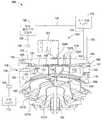
도 1 및 도 2를 참조하면, 장치(100)는 챔버(102), 가스 전달 시스템(125), 원격 플라즈마 공급원(126), 및 진공 시스템(112)을 포함한다. 챔버(102)는 프로세싱 체적부(108)를 둘러싸는 챔버 본체(103)를 포함한다. 챔버 본체(103)는 스테인리스 스틸 또는 알루미늄과 같은 물질을 포함할 수 있다. 샤워헤드 조립체(104) 또는 가스 분배 플레이트가 프로세싱 체적부(108)의 일 단부에 배치되고, 그리고 캐리어 플레이트(114)가 프로세싱 체적부(108)의 타 단부에 배치된다. 본원 발명을 실시하도록 구성될 수 있는 예시적인 샤워헤드가 2007년 10월 16일자로 출원된 'MULTI-GAS STRAIGHT CHANNEL SHOWERHEAD'라는 명칭의 미국 특허 출원 11/873,132, 2007년 10월 16일자로 출원된 'MULTI-GAS STRAIGHT CHANNEL SHOWERHEAD'라는 명칭의 미국 특허 출원 11/873,141, 및 2007년 10월 16일자로 출원된 'MULTI-GAS CONCENTRIC INJECTION SHOWERHEAD'라는 명칭의 미국 특허 출원 11/873,170에 기재되어 있으며, 상기 특허 출원은 인용에 의해 그 전체가 본원 명세서에 병합된다. 빛이 통과하여 기판(140)을 복사 가열할 수 있게 하도록 구성된 투명 물질(119)이 하부 체적부(110)의 일 단부에 배치되고 그리고 캐리어 플레이트(114)가 하부 체적부(110)의 타 단부에 배치된다. 투명 물질(119)은 돔 형상을 가질 수 있다. 캐리어 플레이트(114)가 프로세스 위치에서 도시되어 있으나, 예를 들어, 기판(140)이 로딩 또는 언로딩될 수 있는 하부 위치로 이동될 수도 있을 것이다.1 and 2,
도 3은 본원 발명의 일 실시예에 따른 캐리어 플레이트를 도시한 사시도이다. 일 실시예에서, 캐리어 플레이트(114)는 하나 또는 둘 이상의 리세스(116)를 포함할 수 있고, 그러한 리세스 내에서는 프로세싱 동안에 하나 또는 둘 이상의 기판(140)이 배치될 수 있다. 일 실시예에서, 캐리어 플레이트(114)가 6개 또는 그보다 많은 기판(140)을 운반하도록 구성된다. 다른 실시예에서, 캐리어 플레이트(114)가 8개의 기판(140)을 운반하도록 구성된다. 다른 실시예에서, 캐리어 플레이트(114)는 18개의 기판을 운반하도록 구성된다. 또 다른 실시예에서, 캐리어 플레이트(114)는 22개의 기판을 운반하도록 구성된다. 상기 개수 보다 많은 또는 그보다 적은 기판(140)이 캐리어 플레이트(114) 상에서 운반될 수 있다는 것을 이해할 수 있을 것이다. 통상적인 기판(140)에는 사파이어, 실리콘 카바이드(SiC), 실리콘, 또는 갈륨 질화물(GaN)이 포함될 수 있을 것이다. 다른 타입의 기판(140), 예를 들어 유리 기판(140)이 프로세싱될 수 있다는 것을 이해할 수 있을 것이다. 기판(140)의 크기는 직경이 50 mm - 100 mm 또는 그보다 클 수 있을 것이다. 캐리어 플레이트(114)의 크기는 200 mm-750 mm가 될 수 있을 것이다. 캐리어 플레이트(114)는 SiC 또는 SiC-코팅형 그라파이트를 포함하는 여러 가지 물질로 형성될 수 있을 것이다. 다른 크기의 기판(140)이 챔버(102) 내에서 그리고 본원 명세서에 기재된 프로세스에 따라서 처리될 수 있다는 것을 이해할 수 있을 것이다.3 is a perspective view showing a carrier plate according to an embodiment of the present invention. In one embodiment, the
캐리어 플레이트(114)는 프로세싱 동안에 축선을 중심으로 회전될 수 있다. 일 실시예에서, 캐리어 플레이트(114)는 약 2 RPM 내지 약 100 RPM으로 회전될 수 있다. 다른 실시예에서, 캐리어 플레이트(114)는 약 30 RPM으로 회전될 수 있다. 캐리어 플레이트(114)를 회전시키는 것은 기판(140)을 균일하게 가열하는 것 그리고 프로세싱 가스를 각 기판(140)에 균일하게 노출시키는 것에 도움을 준다. 일 실시예에서, 캐리어 플레이트(114)가 받침대 플레이트(115)를 포함하는 캐리어 지지 장치에 의해서 지지된다. 본원 발명을 실시하도록 구성될 수 있는 예시적인 기판 지지 구조물이 2006년 10월 24일자로 출원된 'SUBSTRATE SUPPORT STRUCTURE WITH RAPID TEMPERATURE CHANGE' 라는 명칭의 미국 특허 출원 11/552,474에 기재되어 있으며, 상기 출원은 인용에 의해 그 전체가 본원 명세서에 병합된다.The
도 4a는 본원 발명의 일 실시예에 따른 받침대 플레이트의 상부 표면을 도시한 사시도이다. 도 4b는 본원 발명의 일 실시예에 따른 받침대 플레이트의 하부 표면을 도시한 사시도이다. 받침대 플레이트(115)는 디스크 형태를 가지고 그리고 실리콘 카바이드가 코팅된 그라파이트 물질로 제조된다. 받침대 플레이트(115)의 상부 표면(156)은 원형 리세스(127)를 구비하도록 형성된다. 원형 리세스(127)는 캐리어 플레이트(114)를 수용하고 지지하기 위한 지지 면적으로서 기능한다. 받침대 플레이트(115)는 승강 핀을 수용하기 위한 3개의 관통홀(158)을 구비한다. 받침대 플레이트(115)는 챔버의 하부 체적부(110) 내에 배치되고 석영으로 제조된 받침대 지지 샤프트(118)에 의해서 하부로부터 3 지점에서 수평으로 지지된다. 받침대 플레이트의 하부 표면(159)은 받침대 지지 샤프트(118)의 승강 아암(arm)을 수용하기 위한 3개의 홀(167)을 구비한다. 받침대 플레이트(115)가 3개의 홀(167)을 구비하는 것으로 설명되었지만, 받침대 지지 샤프트(118)의 승강 아암의 개수에 상응하는 임의 개수의 홀이 이용될 수도 있을 것이다.4A is a perspective view illustrating an upper surface of a pedestal plate according to an embodiment of the present invention. Figure 4b is a perspective view of the lower surface of the pedestal plate according to an embodiment of the present invention. The
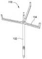
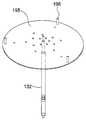
승강 기구(150)가 도 5a-5c 및 도 6을 참조하여 설명될 것이다. 도 5a는 받침대 지지 샤프트의 사시도이고 도 6은 캐리어 플레이트 승강 기구의 사시도이다. 받침대 지지 샤프트(118)는 중앙 샤프트(132)를 포함하고, 3개의 승강 아암(134)이 상기 중앙 샤프트(132)로부터 방사상으로 연장한다. 받침대 지지 샤프트(118)가 3개의 승강 아암(134)을 구비하는 것으로 설명되어 있지만, 3개 보다 많은 개수의 임의의 승강 아암이 이용될 수도 있을 것이며, 예를 들어, 받침대 지지 샤프트(118)가 도 5b에 도시된 바와 같이 6개의 승강 아암(192)을 구비할 수도 있을 것이다. 도 5c에 도시된 일 실시예에서, 승강 아암이 디스크(195)에 의해서 대체되며, 이때 지지 포스트(196)가 디스크(195)의 표면으로부터 연장하여 받침대 플레이트(115)를 지지한다.The
캐리어 플레이트 승강 기구(150)는 받침대 지지 샤프트(118)의 중앙 샤프트(132)를 둘러싸도록 정렬된 수직 가동(可動) 승강 튜브(152), 상기 승강 튜브(152)를 상하로 이동시키기 위한 구동 유닛(도시되지 않음), 상기 승강 튜브(152)로부터 방사상으로 연장하는 3개의 승강 아암(154), 및 관통하도록 형성된 각각의 관통 홀(158)을 통해서 받침대 플레이트(115)의 바닥 표면으로부터 현수(suspend)되는 승강 핀(157)을 포함한다. 이러한 구성에서 승강 튜브(152) 및 승강 아암(154)을 상승시키기 위해서 구동 유닛이 제어될 때, 승강 핀(157)은 승강 아암(154)의 말단부에 의해서 밀어 올려지며, 그에 따라 캐리어 플레이트(114)가 상승된다.The carrier
도 1에 도시된 바와 같이, 하부 돔(119) 아래쪽에 배치된 복수의 내측 램프(121A), 복수의 중앙 램프(121B), 및 복수의 외측 램프(121C)에 의해서 복사 가열이 제공될 수 있다. 반사부(166)를 이용하여 챔버(102)가 내측, 중앙, 외측 램프(121A, 121B, 121C)에 의해서 제공되는 복사 에너지에 대해서 노출되는 것에 대한 제어를 도울 수 있을 것이다. 또한, 기판(140)의 보다 미세한 온도 제어를 위해서 램프의 추가적인 영역을 이용할 수 있을 것이다. 일 실시예에서, 반사부(166)가 금으로 코팅된다. 다른 실시예에서, 반사부(166)가 알루미늄, 로듐, 니켈, 이들의 조합, 또는 다른 고반사 물질로 코팅된다. 일 실시예에서, 램프당 2 킬로와트의 24개의 램프가 영역마다 배치되어 총 72개의 램프가 제공된다. 일 실시예에서, 램프는 공냉식으로 냉각되고 램프의 베이스는 수냉식으로 냉각된다.As shown in FIG. 1, radiant heating may be provided by a plurality of
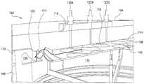
복수의 내측 램프, 중앙 램프 및 외측 램프(121A, 121B, 121C)가 동심적인 영역 또는 다른 영역(도시되지 않음)에 배열될 수 있고, 그리고 각각의 영역에 독립적으로 파워가 제공되어 온도 제어를 통한 증착 속도 및 성장 속도의 조정을 가능하게 할 수 있을 것이다. 일 실시예에서, 고온계(122A, 122B, 122C)와 같은 하나 또는 둘 이상의 온도 센서가 샤워헤드 조립체(104) 내에 배치되어 기판(140) 및 캐리어 플레이트(114)의 온도를 측정할 수 있을 것이고, 그러한 온도 데이터가 제어부(도시되지 않음)로 전송될 수 있을 것이며, 상기 제어부는 각 영역에 대한 파워를 조정하여 캐리어 플레이트(114)에 걸쳐 미리 규정된 온도 프로파일을 유지할 수 있을 것이다. 일 실시예에서, 불활성 가스가 고온계(122A, 122B, 122C) 주위를 돌아서 프로세싱 체적부(108) 내로 유동하여 고온계(122A, 122B, 122C) 상에서 증착 및 응축이 발생되는 것을 방지한다. 고온계(122A, 122B, 122C)는 표면에서의 증착으로 인한 방사율(emissivity) 변화를 자동적으로 보상할 수 있다. 3개의 고온계(122A, 122B, 122C)가 도시되어 있지만, 임의 개수의 고온계가 이용될 수 있다는 것을 이해해야 할 것이며, 예를 들어, 만약 추가적인 램프의 영역이 부가된다면, 각각의 추가적인 영역을 모니터링하기 위해서 추가적인 고온계를 부가하는 것이 바람직할 수 있다. 다른 실시예에서, 각 램프 영역에 대한 파워를 조정하여 전구체 유동 또는 전구체 농도 불균일성을 보상할 수 있을 것이다. 예를 들어, 만약 전구체 농도가 외측 램프 영역에 인접한 캐리어 플레이트(114) 지역에서 낮다면, 외측 램프 영역에 대한 파워를 조정하여 해당 지역에서의 전구체 고갈을 보상하는데 도움을 줄 수도 있을 것이다. 저항식 가열 방식보다 램프 가열 방식을 이용하는 이점 중에는 캐리어 플레이트(114) 표면에 걸친 온도 범위(range)가 작다는 것이 있는데, 이는 제품 수율을 향상시킨다. 신속 가열 및 신속 냉각이 가능한 램프의 능력은 처리량(throughput)을 증대시킬 것이고 그리고 또한 명확한(sharp) 필름 경계면을 생성하는데 도움이 될 것이다.A plurality of inner lamps, center lamps and
반사(reflectance) 모니터(123), 열전쌍(도시되지 않음), 또는 기타 온도 장치와 같은 다른 계량(metrology) 장치가 챔버(102)와 커플링될 수도 있을 것이다. 그러한 계량 장치를 이용하여 두께, 조도(roughness), 조성, 온도 또는 기타 특성과 같은 다양한 필름 특성을 측정할 수 있을 것이다. 이들 측정치를 자동화된 실시간 피드백 제어 루프에서 이용하여 증착 속도 및 상응하는 증착 두께와 같은 프로세스 조건을 제어할 수 있을 것이다. 일 실시예에서, 반사 모니터(123)가 중앙 도관(도시되지 않음)을 통해서 샤워헤드 조립체(104)와 커플링된다. 챔버 계량과 관련한 다른 내용이 2008년 1월 31일자로 출원된 'CLOSED LOOP MOCVD DEPOSITION CONTROL' 라는 명칭의 미국 특허 출원(attorney docket no. 011007)에 기재되어 있으며, 상기 특허는 인용에 의해 그 전체가 본원 명세서에 병합된다.Other metrology devices, such as reflection monitor 123, thermocouples (not shown), or other temperature devices may be coupled with
내측, 중앙 및 외측 램프(121A, 121B, 121C)가 기판(140)의 온도를 약 섭씨 400도 내지 약 섭씨 1200도까지 가열할 수 있을 것이다. 본원 발명이 이러한 내측, 중앙, 및 외측 램프(121A, 121B, 121C)의 어레이를 이용하는 것으로 제한되지 않는다는 것을 이해할 수 있을 것이다. 임의의 적절한 열 공급원을 이용하여 적절한 온도가 챔버(102) 및 그 내부의 기판(140)으로 적절하게 인가되도록 보장할 수도 있을 것이다. 예를 들어, 다른 실시예에서, 열 공급원에 캐리어 플레이트(114)와 열적으로 접촉하는 저항형 가열 요소(도시되지 않음)가 포함될 수도 있을 것이다.Inner, center and
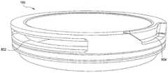
도 2 및 도 7을 참조하며, 도 7은 본원 발명의 일 실시예에 따른 배출(exhaust) 프로세스 키트의 사시도이다. 일 실시예에서, 프로세스 키트가 광 차폐부(117), 배출 링(120), 및 배출 실린더(160)를 포함할 수 있을 것이다. 도 2에 도시된 바와 같이, 광 차폐부(117)가 캐리어 플레이트(114)의 둘레 주위로 배치될 수 있다. 광 차폐부(117)는 내측 램프(121A), 중앙 램프(121B), 및 외측 램프(121C)로부터 받침대 직경의 외부로 벗어나는 에너지를 흡수하고 그리고 챔버(102)의 내부를 향해서 에너지를 재지향시키는 것을 돕는다. 광 차폐부(117)는 또한 직접적인 램프 복사 에너지가 계량 툴과 간섭하는 것을 차단한다. 일 실시예에서, 광 차폐부(117)는 내측 엣지 및 외측 엣지를 구비하는 환형 링을 일반적으로 포함한다. 일 실시예에서, 환형 링의 외측 엣지가 상향으로 각도를 이룬다. 광 차폐부(117)는 일반적으로 실리콘 카바이드를 포함한다. 광 차폐부(117)는 또한 세라믹과 같이 전자기 에너지를 흡수하는 대안적인 물질을 포함할 수도 있을 것이다. 광 차폐부(117)는 배출 실린더(160), 배출 링(120) 또는 챔버 본체(103)의 다른 부분과 커플링될 수 있을 것이다. 일반적으로, 광 차폐부(117)는 받침대 플레이트(115) 또는 캐리어 플레이트(114)와 접촉하지 않는다.2 and 7, which is a perspective view of an exhaust process kit according to one embodiment of the present invention. In one embodiment, the process kit may include a
일 실시예에서, 배출 링(120)이 캐리어 플레이트(114)의 둘레 주위로 배치되어 하부 체적부(110)에서 증착이 발생하지 않도록 돕고 그리고 또한 배출 가스를 챔버(102)로부터 배출 포트(109)로 지향하는 것을 돕는다. 일 실시예에서, 배출 링(120)이 실리콘 카바이드를 포함한다. 배출 링(120)은 또한 세라믹과 같이 전자기 에너지를 흡수하는 대안적인 물질을 포함할 수 있을 것이다.In one embodiment, the
일 실시예에서, 배출 링(120)이 배출 실린더(160)와 커플링된다. 일 실시예에서, 배출 실린더(160)는 배출 링(120)과 수직이 된다. 배출 실린더(160)는 중심으로부터 외측으로 캐리어 플레이트(114)의 표면을 가로지르는 균일하고 균등한 방사상 유동을 유지하는 것을 돕고 그리고 프로세스 체적부(108)의 외부로 그리고 환형 배출 채널(105) 내로 가스가 유동하는 것을 제어한다. 배출 실린더(160)는 내측 측벽(162) 및 외측 측벽(163)을 구비하는 환형 링(161)을 포함하며, 관통 홀 또는 슬롯(165)이 상기 측벽을 통해서 연장하고 그리고 링(161)의 둘레에 걸쳐서 균일한 간격으로 배치된다. 일 실시예에서, 배출 실린더(160) 및 배출 링(120)이 일체형 피스(piece)를 포함한다. 일 실시예에서, 배출 링(120) 및 배출 실린더(160)는 당업계에 공지된 부착 기술을 이용하여 서로 커플링될 수 있는 독립된 피스를 포함한다. 도 2를 참조하면, 프로세스 가스가 샤워헤드 조립체(104)로부터 캐리어 플레이트(114)를 향해서 아래쪽으로 유동하고, 그리고 광 차폐부(117)를 넘어 방사상 외측으로, 배출 실린더(160) 내의 슬롯(165)을 통해서 그리고 환형 배출 채널(105)내로 이동하며, 상기 배출 채널 내에서 상기 가스가 최종적으로 배출 포트(109)를 통해서 챔버(102)로부터 빠져나오게 된다. 배출 실린더(160) 내의 슬롯은 프로세스 가스의 유동을 초킹(choke; 통과 면적을 좁게 하는 것)하여, 전체 받침대 플레이트(115)에 걸쳐 균일한 방사상 유동이 되도록 돕는다. 일 실시예에서, 불활성 가스가 광 차폐부(117)와 배출 링(120) 사이에 형성된 갭을 통해서 상향 유동함으로써 프로세스 가스가 챔버(102)의 하부 체적부(110) 내로 유입되는 것을 방지하고 그리고 하부 돔(119) 상에 증착이 일어나는 것을 방지한다. 하부 돔(119) 상의 증착은 온도 균일도에 영향을 미칠 수 있고 그리고 일부 경우에 하부 돔(119)을 가열하여 그 하부 돔에 균열을 일으킬 수도 있을 것이다.In one embodiment, the
가스 전달 시스템(125)은 다수의 가스 공급원을 포함할 수 있고, 또는 실시되는 프로세스에 따라서 공급원 중 일부가 기체가 아닌 액체 공급원이 될 수도 있을 것이며, 그러한 경우에 가스 전달 시스템은 액체 주입 시스템 또는 액체를 기화시키기 위한 다른 수단(예를 들어, 버블러)을 포함할 수 있을 것이다. 이어서, 증기가 챔버(102)로 전달되기에 앞서서 캐리어 가스와 혼합될 수 있다. 전구체 가스, 캐리어 가스, 퍼지 가스, 세정/에칭 가스 등과 같은 여러 가지 가스가 가스 전달 시스템(125)으로부터 샤워헤드 조립체(104)로의 독립적인 공급 라인(131, 135)으로 공급될 것이다. 공급 라인은 차단 밸브 및 질량 유동 제어장치 또는 각 라인 내의 가스의 유동을 모니터링하고 조정 또는 차단하기 위한 다른 타입의 제어 장치를 포함할 수 있을 것이다. 일 실시예에서, 전구체 가스 농도는 증기압 곡선 그리고 가스 공급원의 위치에서 측정된 압력 및 온도를 기초로 추정된다. 다른 실시예에서, 가스 전달 시스템(125)은 가스 공급원의 하류에 위치되고 시스템 내의 전구체 가스 농도의 직접적인 측정을 제공하는 모니터를 포함한다.
도관(129)은 원격 플라즈마 공급원(126)으로부터 세정/에칭 가스를 제공받을 수 있다. 원격 플라즈마 공급원(126)은 공급 라인(124)을 통해서 가스 전달 시스템(125)으로부터 가스를 제공받을 수 있으며, 그리고 밸브(130)가 샤워헤드 조립체(104)와 원격 플라즈마 공급원(126) 사이에 배치될 수 있다. 플라즈마용 도관으로서 기능하도록 구성될 수 있는 공급 라인(133)을 통해서 세정 및/또는 에칭 가스 또는 플라즈마가 샤워헤드 조립체(104) 내로 유동할 수 있게 하기 위해, 밸브(130)가 개방될 수 있다. 다른 실시예에서, 세정/에칭 가스가 비-플라즈마(non-plasma) 세정 및/또는 에칭을 위해서 교호식(alternate) 공급 라인 구성을 이용하여 가스 전달 시스템(125)으로부터 샤워헤드 조립체(104)로 전달될 수 있을 것이다. 또 다른 실시예에서, 플라즈마가 샤워헤드 조립체(104)를 우회하고 그리고 샤워헤드 조립체(104)를 가로지르는(traverse) 도관(도시되지 않음)을 통해서 챔버(102)의 프로세싱 체적부(108)로 직접 유동된다.
원격 플라즈마 공급원(126)이 챔버(102) 세정 및/또는 기판(140) 에칭을 위해서 구성된 무선 주파수 또는 마이크로파 플라즈마 공급원일 수 있을 것이다. 세정 및/또는 에칭 가스가 공급 라인(124)을 통해서 원격 플라즈마 공급원(126)으로 공급되어 플라즈마 종(species)을 생성할 수 있을 것이며, 그러한 플라즈마 종은 도관(129) 및 공급 라인(133)을 통해서 전달되어 샤워헤드 조립체(104)를 통해서 챔버(102) 내로 분산될 수 있다. 세정 용도를 위한 가스는 불소, 염소 또는 기타 반응성 원소를 포함할 수 있을 것이다.The
다른 실시예에서, 전구체 가스가 원격 플라즈마 공급원(126)으로 공급되어 플라즈마 종을 생성하도록 가스 전달 시스템(125) 및 원격 플라즈마 공급원(126)이 적절하게 구성될 수 있을 것이며, 상기 플라즈마 종은 샤워헤드 조립체(104)를 통해서 전달되어 예를 들어 Ⅲ-Ⅴ 필름과 같은 CVD 층을 기판(140) 상에 증착할 수 있을 것이다.In other embodiments, the
퍼지 가스(예를 들어, 질소)가 캐리어 플레이트(114)의 아래쪽에 그리고 챔버 본체(103)의 바닥 부근에 배치된 유입구 포트나 튜브(도시되지 않음)로부터 및/또는 샤워헤드 조립체(104)로부터 챔버(102) 내로 전달될 수 있다. 퍼지 가스는 챔버(102)의 하부 체적부(110)로 유입되고 그리고 캐리어 플레이트(114) 및 배출 링(120)을 지나서 위쪽으로 그리고 환형 배출 채널(105) 주위에 배치된 다수의 배출 포트(109) 내로 유동한다. 배출 도관(106)은 진공 펌프(도시되지 않음)를 포함하는 진공 시스템(112)에 환형 배출 채널(105)을 연결한다. 배출 가스가 환형 배출 채널(105)로부터 인출되는 속도를 제어하는 밸브 시스템(107)을 이용하여 챔버(102) 압력을 제어할 수 있을 것이다.Purge gas (eg, nitrogen) is from an inlet port or tube (not shown) disposed below the
샤워헤드 조립체(104)는 기판(140)을 프로세싱하는 동안에 캐리어 플레이트(114) 부근에 위치된다. 일 실시예에서, 프로세싱 동안에 샤워헤드 조립체(104)로부터 캐리어 플레이트(114)까지의 거리는 약 4 mm 내지 약 40 mm일 수 있다.The
기판 프로세싱 동안에, 본원 발명의 일 실시예에 따라, 프로세스 가스가 샤워헤드 조립체(104)로부터 기판(140)의 표면을 향해서 유동한다. 프로세스 가스는 하나 또는 둘 이상의 전구체 가스 그리고 상기 전구체 가스와 혼합될 수 있는 캐리어 가스 및 도펀트 가스를 포함할 수 있다. 프로세스 가스가 기판(140)에 대해서 실질적으로 접선방향으로 유동하고 그리고 기판(140)의 증착 표면에 걸쳐서 방사상 방향으로 균일하게 층류 유동으로 분포될 수 있도록 환형 배출 채널(105)의 인출(draw)은 가스 유동에 영향을 미칠 수 있다. 프로세싱 체적부(108)는 약 760 Torr 내지 약 80 Torr 까지의 압력으로 유지될 수 있다.During substrate processing, in accordance with one embodiment of the present invention, process gas flows from the
기판(140) 표면에서의 또는 그 부근에서의 프로세스 가스 전구체의 반응은 GaN, 알루미늄 질화물(AlN), 및 인듐 질화물(InN)을 포함하는 여러 가지 금속 질화물 층을 기판(140) 상에 증착할 수 있다. 다수의 금속이 또한 AlGaN 및/또는 InGaN과 같은 다른 화합물 필름의 증착에 이용될 수 있을 것이다. 추가적으로, 실리콘(Si) 또는 마그네슘(Mg)과 같은 도펀트가 필름에 부가될 수 있을 것이다. 증착 프로세스 동안에 적은 양의 도펀트 가스를 부가함으로써 필름이 도핑될 수 있을 것이다. 실리콘 도핑의 경우에, 예를 들어, 실란(SiH4) 또는 디실란(Si2H6) 가스가 사용될 수 있고, 그리고 도펀트 가스가 마그네슘 도핑을 위해서 Bis(시클로펜타다에닐; cyclopentadienyl) 마그네슘(Cp2Mg 또는 (C5H5)2Mg)을 포함할 수 있을 것이다.The reaction of the process gas precursor at or near the surface of the
일 실시예에서, 불소계 또는 염소계 플라즈마를 에칭 또는 세정에 이용할 수 있을 것이다. 다른 실시예에서, Cl2, Br, 및 I2와 같은 할로겐 가스 또는 HCl, HBr, 및 HI와 같은 할라이드를 비-플라즈마 에칭에 이용할 수도 있을 것이다.In one embodiment, fluorine-based or chlorine-based plasma may be used for etching or cleaning. In other embodiments, halogen gases such as Cl2 , Br, and I2 or halides such as HCl, HBr, and HI may be used for non-plasma etching.
일 실시예에서, 질소 가스(N2), 수소 가스(H2), 아르곤(Ar) 가스, 기타 불활성 가스 또는 그들의 조합을 포함할 수 있는 캐리어 가스가 샤워헤드 조립체(104)로 전달되기에 앞서서 제 1 및 제 2 전구체 가스와 혼합될 수 있을 것이다.In one embodiment, a carrier gas, which may include nitrogen gas (N2 ), hydrogen gas (H2 ), argon (Ar) gas, or other inert gas, or a combination thereof, prior to delivery to the
일 실시예에서, 제 1 전구체 가스가 그룹 III 전구체를 포함할 수 있고, 그리고 제 2 전구체 가스가 그룹 V 전구체를 포함할 수 있을 것이다. 그룹 III 전구체는 트리메틸 갈륨("TMG"), 트리에틸 갈륨(TEG), 트리메틸 알루미늄("TMAl"), 및/또는 트리메틸 인듐("TMI")과 같은 금속 유기(metal organic; MO) 전구체일 수 있을 것이나, 다른 적절한 MO 전구체도 이용될 수 있을 것이다. 그룹 V 전구체는 암모니아(NH3)와 같은 질소 전구체일 수 있을 것이다.In one embodiment, the first precursor gas may comprise a Group III precursor, and the second precursor gas may comprise a Group V precursor. Group III precursors may be metal organic (MO) precursors such as trimethyl gallium ("TMG"), triethyl gallium (TEG), trimethyl aluminum ("TMAl"), and / or trimethyl indium ("TMI"). There may be other suitable MO precursors, though. The group V precursor may be a nitrogen precursor, such as ammonia (NH3 ).
도 8a는 본원 발명의 일 실시예에 따른 상부 라이너를 도시한 사시도이다. 도 8b는 본원 발명의 일 실시예에 따른 하부 라이너를 도시한 사시도이다. 일 실시예에서, 프로세스 챔버(102)는 프로세스 가스에 의한 에칭으로부터 챔버 본체(103)를 보호하도록 돕는 상부 프로세스 라이너(170) 및 하부 프로세스 라이너(180)를 더 포함한다. 일 실시예에서는, 상부 프로세스 라이너(170) 및 하부 프로세스 라이너(180)가 일체형 본체로 구성된다. 다른 실시예에서는, 상부 프로세스 라이너(170) 및 하부 프로세스 라이너(180)가 독립된 피스로 구성된다. 하부 프로세스 라이너(180)는 프로세스 챔버(102)의 하부 체적부(110) 내에 배치되고 그리고 상부 프로세스 라이너(170)는 샤워헤드 조립체(104)에 인접하여 배치된다. 일 실시예에서, 상부 프로세스 라이너(170)는 하부 프로세스 라이너(180) 상에 놓인다. 일 실시예에서, 하부 프로세스 라이너(180)는 배출 포트(109)의 일부를 형성할 수 있는 배출 포트(804) 개구부 및 슬릿 밸브 포트(802)를 구비한다. 상부 프로세스 라이너(170)는 환형 배출 채널(105)의 일부를 형성할 수 있는 배출 환형부(806)를 구비한다. 라이너는 불투명한 석영, 사파이어, PBN 물질, 세라믹, 이들의 유도체 또는 이들의 조합과 같은 열적 절연 물질을 포함할 수 있을 것이다.8A is a perspective view illustrating an upper liner according to an embodiment of the present invention. 8B is a perspective view illustrating a lower liner according to an embodiment of the present invention. In one embodiment, the
균일한 전구체 유동 및 혼합을 제공하면서도 보다 큰 기판 및 보다 큰 증착 영역에 걸친 균일한 온도를 유지하는 개선된 증착 장치 및 프로세스가 제공된다. 보다 큰 기판 및/또는 다수의 기판 그리고 보다 큰 증착 면적에 걸친 균일한 혼합 및 가열이 수율 및 처리량 증대에 있어서 바람직하다. 보다 균일한 가열 및 혼합이 중요한 요소인데, 이는 그들이 전자 소자의 생산비에 직접적으로 영향을 미치기 때문이고, 그리고 그에 따라 소자 제조업자의 시장에서의 경쟁력에 직접적으로 영향을 미치기 때문이다.Improved deposition apparatus and processes are provided that provide uniform precursor flow and mixing while maintaining uniform temperature across larger substrates and larger deposition areas. Larger substrates and / or multiple substrates and uniform mixing and heating over a larger deposition area are desirable in yield and throughput enhancement. More uniform heating and mixing is an important factor because they directly affect the production cost of electronic devices, and therefore directly affect the competitiveness of device manufacturers in the market.
이상에서 본원 발명의 실시예에 대해서 설명하였지만, 본원 발명의 다른 실시예 및 추가적인 실시예가 본원 발명의 기본적인 범위 내에서 안출될 수 있을 것이고, 그에 따라 본원 발명의 범위는 이하의 특허청구범위에 의해서 결정된다 할 것이다.
While the embodiments of the present invention have been described above, other and further embodiments of the present invention may be devised within the basic scope of the present invention, and thus the scope of the present invention is determined by the following claims. Will be done.
Claims (33)
Translated fromKorean복수의 기판이 배치되는 기판 캐리어 플레이트를 지지하도록 구성된 받침대;
상기 복수의 기판 중 각각의 표면을 향하여 하나 또는 둘 이상의 프로세스 가스를 유동시키기 위한 샤워헤드 조립체; 및
상기 받침대 아래에 위치되고 그리고 상기 복수의 기판을 향하여 복사 열을 지향시켜 하나 또는 둘 이상의 복사 열 영역을 생성하도록 구성된 복수의 램프; 및
하나 또는 둘 이상의 고온계;를 포함하고,
상기 하나 또는 둘 이상의 복사 열 영역은
내측 복사 열 영역,
상기 내측 복사 열 영역 위에 위치된 중앙 복사 열 영역,
상기 중앙 복사 열 영역 위에 위치된 외측 복사 열 영역을 포함하며,
각각의 복사 열 영역이 동심적인 램프의 어레이를 형성하고,
상기 하나 또는 둘 이상의 고온계는
상기 샤워헤드 조립체 내에 배치되어 기판 온도를 측정하고,
상기 하나 또는 둘 이상의 복사 열 영역의 각각과 연관되고 그리고
상기 복수의 기판에 걸쳐 미리결정된 온도 프로파일를 유지하기 위해서 상기 하나 또는 둘 이상의 복사 열 영역의 온도를 조정하도록 구성된 제어부에 연결되는,
기판 프로세싱 장치.
1. A substrate processing apparatus comprising:
A pedestal configured to support a substrate carrier plate on which a plurality of substrates are disposed;
A showerhead assembly for flowing one or more process gases toward each surface of the plurality of substrates; And
A plurality of lamps positioned below the pedestal and configured to direct radiant heat towards the plurality of substrates to create one or more radiant heat regions; And
One or more pyrometers;
The one or more radiant thermal areas
Inner radiant heat zone,
A central radiant heat zone located above said inner radiant heat zone,
An outer radiation heat zone located above said central radiation heat zone,
Each radiant heat zone forms an array of concentric lamps,
The one or more pyrometers
Disposed in the showerhead assembly to measure substrate temperature,
Associated with each of said one or more radiant thermal regions and
Coupled to a control configured to adjust the temperature of the one or more radiant heat zones to maintain a predetermined temperature profile across the plurality of substrates,
Substrate processing apparatus.
상기 하나 또는 둘 이상의 고온계의 적어도 부분적인 주위로 불활성 가스를 전달하도록 구성된 가스 공급원을 더 포함하는
기판 프로세싱 장치.
The method of claim 1,
Further comprising a gas source configured to deliver an inert gas to at least part of the surroundings of the one or more pyrometers
Substrate processing apparatus.
복수의 기판을 지지하도록 구성된 받침대;
상기 복수의 기판 중 각각의 표면을 향하여 하나 또는 둘 이상의 프로세스 가스를 유동시키기 위한 샤워헤드 조립체;
상기 받침대 아래에 위치되고 그리고 상기 복수의 기판을 향하여 복사 열을 지향시켜 하나 또는 둘 이상의 복사 열 영역을 생성하도록 구성된 복수의 램프; 및
상기 받침대 위쪽에 배치된 반사 모니터;를 포함하는
기판 프로세싱 장치.
1. A substrate processing apparatus comprising:
A pedestal configured to support the plurality of substrates;
A showerhead assembly for flowing one or more process gases toward each surface of the plurality of substrates;
A plurality of lamps positioned below the pedestal and configured to direct radiant heat towards the plurality of substrates to create one or more radiant heat regions; And
And a reflection monitor disposed above the pedestal.
Substrate processing apparatus.
상기 반사 모니터가 상기 샤워헤드 조립체와 커플링되고 복수의 기판 중 하나 또는 둘 이상의 기판 상에 배치된 필름의 두께, 조도 및 조성 중 하나 또는 둘 이상을 측정하도록 구성되는
기판 프로세싱 장치.
The method of claim 7, wherein
The reflective monitor is coupled to the showerhead assembly and configured to measure one or more of the thickness, roughness and composition of the film disposed on one or more substrates of the plurality of substrates
Substrate processing apparatus.
복수의 기판이 배치되는 기판 캐리어 플레이트를 지지하도록 구성된 받침대;
상기 복수의 기판 중 각각의 표면을 향하여 하나 또는 둘 이상의 프로세스 가스를 유동시키기 위한 샤워헤드 조립체;
상기 받침대 아래에 위치되고 그리고 상기 복수의 기판을 향하여 복사 열을 지향시켜 하나 또는 둘 이상의 복사 열 영역을 생성하도록 구성된 복수의 램프; 및
상기 받침대 직경의 외부로 벗어나는 에너지를 흡수하도록 상기 받침대의 둘레 주위에 배치된 광 차폐부;를 포함하는
기판 프로세싱 장치.
A substrate processing apparatus,
A pedestal configured to support a substrate carrier plate on which a plurality of substrates are disposed;
A showerhead assembly for flowing one or more process gases toward each surface of the plurality of substrates;
A plurality of lamps positioned below the pedestal and configured to direct radiant heat towards the plurality of substrates to create one or more radiant heat regions; And
And a light shield disposed around the perimeter of the pedestal to absorb energy escaping outside of the pedestal diameter.
Substrate processing apparatus.
상기 광 차폐부의 둘레를 둘러싸는 배출 링을 더 포함하는
기판 프로세싱 장치.
The method of claim 9,
And a discharge ring surrounding the light shielding portion.
Substrate processing apparatus.
상기 배출 링에 커플링된 배출 실린더를 더 포함하는
기판 프로세싱 장치.
11. The method of claim 10,
Further comprising a discharge cylinder coupled to the discharge ring
Substrate processing apparatus.
상기 배출 실린더가, 상기 기판 캐리어 플레이트의 표면을 가로질러 중앙으로부터 외측으로 하나 또는 둘 이상의 프로세스 가스의 균일하고 균등한 방사상 유동을 유지하기 위해서 관통 형성된 복수의 슬롯을 구비하는
기판 프로세싱 장치.
The method of claim 11,
The discharge cylinder has a plurality of slots formed therethrough so as to maintain a uniform and even radial flow of one or more process gases from the center outwards across the surface of the substrate carrier plate.
Substrate processing apparatus.
복수의 기판을 지지하도록 구성된 받침대;
상기 복수의 기판 중 각각의 표면을 향하여 하나 또는 둘 이상의 프로세스 가스를 유동시키기 위한 샤워헤드 조립체;
상기 받침대 아래에 위치되고 그리고 상기 복수의 기판을 향하여 복사 열을 지향시켜 하나 또는 둘 이상의 복사 열 영역을 생성하도록 구성된 복수의 램프; 및
상기 샤워 헤드 조립체에 커플링되고 상기 복수의 기판의 하나 또는 둘 이상의 특성을 측정하도록 구성된 하나 또는 둘 이상의 계량 장치;를 포함하는
기판 프로세싱 장치.
1. A substrate processing apparatus comprising:
A pedestal configured to support the plurality of substrates;
A showerhead assembly for flowing one or more process gases toward each surface of the plurality of substrates;
A plurality of lamps positioned below the pedestal and configured to direct radiant heat towards the plurality of substrates to create one or more radiant heat regions; And
One or more metering devices coupled to the shower head assembly and configured to measure one or more characteristics of the plurality of substrates;
Substrate processing apparatus.
상기 하나 또는 둘 이상의 복사 열 영역이 내측 영역, 중앙 영역, 및 외측 영역을 포함하며, 각각의 복사 열 영역이 동심적인 램프의 어레이를 형성하고, 그리고 상기 외측 영역이 상기 중앙 영역 위에 위치되는
기판 프로세싱 장치.
The method of claim 13,
Wherein said one or more radiant heat regions comprise an inner region, a central region, and an outer region, each radiant thermal region forming an array of concentric lamps, and wherein said outer region is located above said central region;
Substrate processing apparatus.
상기 하나 또는 둘 이상의 계량 장치가 하나 또는 둘 이상의 고온계를 더 포함하고,
상기 하나 또는 둘 이상의 고온계는,
상기 샤워헤드 조립체 내에 배치되고,
각각의 복사 열 영역과 연관되고 그리고
복수의 기판에 걸쳐 미리 결정된 온도 프로파일를 유지하기 위해서 복사 열 영역의 온도를 조정하도록 구성된 제어부에 연결되는
기판 프로세싱 장치.
The method of claim 15,
The one or more metering devices further comprise one or more pyrometers,
The one or more pyrometers,
Disposed in the showerhead assembly,
Associated with each radiant heat zone and
Coupled to a control configured to adjust the temperature of the radiant heat zone to maintain a predetermined temperature profile across the plurality of substrates.
Substrate processing apparatus.
상기 하나 또는 둘 이상의 계량 장치가 상기 샤워헤드 조립체와 커플링되는 반사 모니터를 포함하는
기판 프로세싱 장치.
The method of claim 13,
The one or more metering devices include a reflective monitor coupled with the showerhead assembly
Substrate processing apparatus.
상기 반사 모니터가 복수의 기판 중 하나 또는 둘 이상의 기판 상에 배치된 필름의 두께, 조도 및 조성 중 하나 또는 둘 이상을 측정하도록 구성되는
기판 프로세싱 장치.
The method of claim 17,
The reflective monitor is configured to measure one or more of the thickness, roughness and composition of the film disposed on one or more substrates of the plurality of substrates
Substrate processing apparatus.
상기 받침대 직경의 외부로 벗어나는 에너지를 흡수하도록 상기 받침대의 둘레 주위에 배치된 광 차폐부를 더 포함하는
기판 프로세싱 장치.
The method of claim 13,
And a light shield disposed around the perimeter of the pedestal to absorb energy deviating outside of the pedestal diameter.
Substrate processing apparatus.
복수의 기판을 지지하도록 구성된 받침대;
상기 복수의 기판 중 각각의 표면을 향하여 하나 또는 둘 이상의 프로세스 가스를 유동시키기 위한 샤워헤드 조립체;
상기 받침대 아래에 위치되고 그리고 상기 복수의 기판을 향하여 복사 열을 지향시켜 하나 또는 둘 이상의 복사 열 영역을 생성하도록 구성된 복수의 램프; 및
상기 샤워헤드 조립체에 커플링되고 상기 복수의 기판의 하나 또는 둘 이상의 특성을 측정하도록 구성된 하나 또는 둘 이상의 계량 장치; 및
상기 하나 또는 둘 이상의 계량 장치의 적어도 부분적인 주위로 불활성 가스를 전달하도록 구성된 가스 공급원;을 포함하는
기판 프로세싱 장치.
1. A substrate processing apparatus comprising:
A pedestal configured to support the plurality of substrates;
A showerhead assembly for flowing one or more process gases toward each surface of the plurality of substrates;
A plurality of lamps positioned below the pedestal and configured to direct radiant heat towards the plurality of substrates to create one or more radiant heat regions; And
One or more metering devices coupled to the showerhead assembly and configured to measure one or more characteristics of the plurality of substrates; And
A gas source configured to deliver an inert gas around at least part of the one or more metering devices
Substrate processing apparatus.
상기 하나 또는 둘 이상의 계량 장치가 상기 샤워헤드 조립체와 커플링되는 반사 모니터를 포함하는
기판 프로세싱 장치.
21. The method of claim 20,
The one or more metering devices include a reflective monitor coupled with the showerhead assembly
Substrate processing apparatus.
상기 하나 또는 둘 이상의 계량 장치가 하나 또는 둘 이상의 고온계를 포함하는
기판 프로세싱 장치.
22. The method of claim 21,
The one or more metering devices comprise one or more pyrometers
Substrate processing apparatus.
상기 받침대 직경의 외부로 벗어나는 에너지를 흡수하도록 상기 받침대의 둘레 주위에 배치된 광 차폐부를 더 포함하는
기판 프로세싱 장치.
21. The method of claim 20,
And a light shield disposed around the perimeter of the pedestal to absorb energy deviating outside of the pedestal diameter.
Substrate processing apparatus.
하나 또는 둘 이상의 기판을 가지는 기판 캐리어를 프로세싱 챔버의 프로세스 체적부 내의 받침대 상으로 위치시키는 단계;
하나 또는 둘 이상의 필름을 하나 또는 둘 이상의 기판 상에 증착(deposit)하기 위해서 샤워헤드 조립체를 통해서 상기 프로세스 체적부 내로 둘 또는 셋 이상의 프로세스 가스를 유동시키는 단계;
상기 받침대 아래에 위치된 복수의 램프를 이용하여 기판 캐리어를 가열하는 단계;
하나 또는 둘 이상의 고온계를 이용하여 프로세스 체적부 내의 온도를 측정하는 단계;
측정된 온도를 기초로 기판 캐리어에 걸쳐 온도 프로파일을 제어하는 단계; 그리고
상기 하나 또는 둘 이상의 고온계의 적어도 부분적인 주위로 불활성 가스를 유동시키는 단계를 포함하는
하나 또는 둘 이상의 기판을 프로세싱하는 방법.
As a method of processing one or more substrates:
Positioning a substrate carrier having one or more substrates onto a pedestal in a process volume of the processing chamber;
Flowing two or more process gases into the process volume through a showerhead assembly to deposit one or more films onto one or more substrates;
Heating the substrate carrier using a plurality of lamps positioned below the pedestal;
Measuring the temperature in the process volume using one or more pyrometers;
Controlling a temperature profile across the substrate carrier based on the measured temperature; And
Flowing an inert gas around at least a portion of the one or more pyrometers
A method of processing one or more substrates.
상기 복수의 램프가 복수의 동심적인 열 영역을 형성하도록 정렬되는
하나 또는 둘 이상의 기판을 프로세싱하는 방법.
The method of claim 25,
Wherein the plurality of lamps are arranged to form a plurality of concentric thermal regions
A method of processing one or more substrates.
상기 하나 이상의 고온계가 각각의 열 영역과 연관되는
하나 또는 둘 이상의 기판을 프로세싱하는 방법.
The method of claim 26,
The one or more pyrometers associated with each thermal zone
A method of processing one or more substrates.
상기 샤워헤드 조립체에 커플링된 계량 장치를 이용하여 하나 또는 둘 이상의 기판 상의 필름 특성을 측정하는 단계를 더 포함하는
하나 또는 둘 이상의 기판을 프로세싱하는 방법.
The method of claim 27,
Measuring film properties on one or more substrates using a metering device coupled to the showerhead assembly;
A method of processing one or more substrates.
상기 하나 또는 둘 이상의 필름 특성이 두께, 조도 및 조성 중 하나 또는 둘 이상을 포함하는
하나 또는 둘 이상의 기판을 프로세싱하는 방법.
29. The method of claim 28,
Wherein the one or more film properties comprise one or more of thickness, roughness and composition
A method of processing one or more substrates.
그룹 III 금속유기 전구체; 및
질소 전구체;를 포함하는 샤워헤드 조립체와 커플링되는 가스 전달 시스템을 더 포함하는
기판 프로세싱 장치.
The method of claim 1,
Group III metalorganic precursors; And
And a gas delivery system coupled with the showerhead assembly including a nitrogen precursor.
Substrate processing apparatus.
상기 하나 또는 둘 이상의 복사 열 영역이 내측 영역, 중앙 영역, 및 외측 영역을 포함하며, 각각의 복사 열 영역이 동심적인 램프의 어레이를 형성하고, 그리고 상기 외측 영역이 상기 중앙 영역 위에 위치되는
기판 프로세싱 장치.
The method of claim 8,
Wherein said one or more radiant heat regions comprise an inner region, a central region, and an outer region, each radiant thermal region forming an array of concentric lamps, and wherein said outer region is located above said central region;
Substrate processing apparatus.
상기 하나 또는 둘 이상의 복사 열 영역이 내측 영역, 중앙 영역, 및 외측 영역을 포함하며, 각각의 복사 열 영역이 동심적인 램프의 어레이를 형성하고, 그리고 상기 외측 영역이 상기 중앙 영역 위에 위치되는
기판 프로세싱 장치.
The method of claim 9,
Wherein said one or more radiant heat regions comprise an inner region, a central region, and an outer region, each radiant thermal region forming an array of concentric lamps, and wherein said outer region is located above said central region;
Substrate processing apparatus.
상기 하나 또는 둘 이상의 복사 열 영역이 내측 영역, 중앙 영역, 및 외측 영역을 포함하며, 각각의 복사 열 영역이 동심적인 램프의 어레이를 형성하고, 그리고 상기 외측 영역이 상기 중앙 영역 위에 위치되는
기판 프로세싱 장치.
21. The method of claim 20,
Wherein said one or more radiant heat regions comprise an inner region, a central region, and an outer region, each radiant thermal region forming an array of concentric lamps, and wherein said outer region is located above said central region;
Substrate processing apparatus.
Applications Claiming Priority (3)
| Application Number | Priority Date | Filing Date | Title |
|---|---|---|---|
| US12/023,520 | 2008-01-31 | ||
| US12/023,520US20090194024A1 (en) | 2008-01-31 | 2008-01-31 | Cvd apparatus |
| PCT/US2009/030858WO2009099720A1 (en) | 2008-01-31 | 2009-01-13 | Cvd apparatus |
Publications (2)
| Publication Number | Publication Date |
|---|---|
| KR20100124257A KR20100124257A (en) | 2010-11-26 |
| KR101296317B1true KR101296317B1 (en) | 2013-08-14 |
Family
ID=40930407
Family Applications (1)
| Application Number | Title | Priority Date | Filing Date |
|---|---|---|---|
| KR1020107018869AActiveKR101296317B1 (en) | 2008-01-31 | 2009-01-13 | Chemical vapor deposition system |
Country Status (6)
| Country | Link |
|---|---|
| US (1) | US20090194024A1 (en) |
| JP (1) | JP2011511459A (en) |
| KR (1) | KR101296317B1 (en) |
| CN (1) | CN101925980B (en) |
| TW (1) | TWI513852B (en) |
| WO (1) | WO2009099720A1 (en) |
Cited By (1)
| Publication number | Priority date | Publication date | Assignee | Title |
|---|---|---|---|---|
| KR101586937B1 (en)* | 2014-08-12 | 2016-01-19 | 주식회사 엘지실트론 | Reactor for EPI wafer |
Families Citing this family (36)
| Publication number | Priority date | Publication date | Assignee | Title |
|---|---|---|---|---|
| US20100206229A1 (en)* | 2008-05-30 | 2010-08-19 | Alta Devices, Inc. | Vapor deposition reactor system |
| US20100139554A1 (en)* | 2008-12-08 | 2010-06-10 | Applied Materials, Inc. | Methods and apparatus for making gallium nitride and gallium aluminum nitride thin films |
| KR20110131291A (en)* | 2009-03-16 | 2011-12-06 | 알타 디바이씨즈, 인크. | Heating lamp system and its method |
| US8110889B2 (en)* | 2009-04-28 | 2012-02-07 | Applied Materials, Inc. | MOCVD single chamber split process for LED manufacturing |
| US20110049779A1 (en)* | 2009-08-28 | 2011-03-03 | Applied Materials, Inc. | Substrate carrier design for improved photoluminescence uniformity |
| KR20120099632A (en)* | 2009-10-07 | 2012-09-11 | 어플라이드 머티어리얼스, 인코포레이티드 | Improved multichamber split processes for led manufacturing |
| WO2011052817A1 (en)* | 2009-10-28 | 2011-05-05 | 엘아이지에이디피 주식회사 | Metal organic chemical vapor deposition device and temperature control method therefor |
| CN104810257A (en)* | 2009-10-28 | 2015-07-29 | 丽佳达普株式会社 | Metal organic chemical vapor deposition equipment and temperature control method thereof |
| US20110256692A1 (en)* | 2010-04-14 | 2011-10-20 | Applied Materials, Inc. | Multiple precursor concentric delivery showerhead |
| US20120009765A1 (en)* | 2010-07-12 | 2012-01-12 | Applied Materials, Inc. | Compartmentalized chamber |
| KR101205433B1 (en)* | 2010-07-28 | 2012-11-28 | 국제엘렉트릭코리아 주식회사 | Substrate susceptor and depositon apparatus using sysceptor |
| WO2012071302A2 (en)* | 2010-11-22 | 2012-05-31 | Applied Materials, Inc. | Interchangeable pumping rings to control path of process gas flow |
| US20120227665A1 (en)* | 2011-03-11 | 2012-09-13 | Applied Materials, Inc. | Apparatus for monitoring and controlling substrate temperature |
| US8404048B2 (en) | 2011-03-11 | 2013-03-26 | Applied Materials, Inc. | Off-angled heating of the underside of a substrate using a lamp assembly |
| JP2014515789A (en)* | 2011-04-20 | 2014-07-03 | コーニンクレッカ フィリップス エヌ ヴェ | Measuring apparatus and method for vapor deposition applications |
| CN103088415B (en)* | 2011-11-03 | 2015-12-02 | 上海华虹宏力半导体制造有限公司 | Improve the method for temperature homogeneity in lamp heating cavity |
| US20130239894A1 (en)* | 2012-03-19 | 2013-09-19 | Pinecone Material Inc. | Chemical vapor deposition apparatus |
| CN102534567B (en)* | 2012-03-21 | 2014-01-15 | 中微半导体设备(上海)有限公司 | Device and method for controlling basal heating in chemical gaseous phase sedimentary chamber |
| JP2013222884A (en) | 2012-04-18 | 2013-10-28 | Furukawa Co Ltd | Vapor growth device and film forming method |
| US9401271B2 (en) | 2012-04-19 | 2016-07-26 | Sunedison Semiconductor Limited (Uen201334164H) | Susceptor assemblies for supporting wafers in a reactor apparatus |
| US9082801B2 (en)* | 2012-09-05 | 2015-07-14 | Industrial Technology Research Institute | Rotatable locating apparatus with dome carrier and operating method thereof |
| US9373534B2 (en) | 2012-09-05 | 2016-06-21 | Industrial Technology Research Institute | Rotary positioning apparatus with dome carrier, automatic pick-and-place system, and operating method thereof |
| TW201437421A (en)* | 2013-02-20 | 2014-10-01 | Applied Materials Inc | Apparatus and methods for carousel atomic layer deposition |
| CN105027275B (en)* | 2013-03-15 | 2018-06-26 | 应用材料公司 | Base supports bar with the uniformity adjustment lens for epitaxial process |
| US9837250B2 (en)* | 2013-08-30 | 2017-12-05 | Applied Materials, Inc. | Hot wall reactor with cooled vacuum containment |
| KR102434364B1 (en) | 2013-09-06 | 2022-08-19 | 어플라이드 머티어리얼스, 인코포레이티드 | Circular lamp arrays |
| US10047457B2 (en)* | 2013-09-16 | 2018-08-14 | Applied Materials, Inc. | EPI pre-heat ring |
| SG11201606004PA (en) | 2014-02-14 | 2016-08-30 | Applied Materials Inc | Upper dome with injection assembly |
| CN104911565B (en)* | 2014-03-11 | 2017-12-22 | 中微半导体设备(上海)有限公司 | A kind of chemical vapor deposition unit |
| US20160033070A1 (en)* | 2014-08-01 | 2016-02-04 | Applied Materials, Inc. | Recursive pumping member |
| JP6210382B2 (en)* | 2014-09-05 | 2017-10-11 | 信越半導体株式会社 | Epitaxial growth equipment |
| EP4138121A1 (en)* | 2015-10-09 | 2023-02-22 | Applied Materials, Inc. | Diode laser for wafer heating for epi processes |
| US10727094B2 (en)* | 2016-01-29 | 2020-07-28 | Taiwan Semiconductor Manufacturing Co., Ltd | Thermal reflector device for semiconductor fabrication tool |
| WO2017165550A1 (en)* | 2016-03-22 | 2017-09-28 | Tokyo Electron Limited | System and method for temperature control in plasma processing system |
| TWI677593B (en) | 2016-04-01 | 2019-11-21 | 美商應用材料股份有限公司 | Apparatus and method for providing a uniform flow of gas |
| WO2020072241A1 (en)* | 2018-10-01 | 2020-04-09 | Applied Materials, Inc. | Purged viewport for quartz dome in epitaxy reactor |
Citations (2)
| Publication number | Priority date | Publication date | Assignee | Title |
|---|---|---|---|---|
| KR20040085267A (en)* | 2003-03-31 | 2004-10-08 | 삼성전자주식회사 | Apparatus for forming an atomic layer on substrate |
| US7128785B2 (en)* | 2001-04-11 | 2006-10-31 | Aixtron Ag | Method for depositing especially crystalline layers from the gas phase onto especially crystalline substrates |
Family Cites Families (44)
| Publication number | Priority date | Publication date | Assignee | Title |
|---|---|---|---|---|
| WO1980000504A1 (en)* | 1978-08-18 | 1980-03-20 | Nat Res Dev | Control of deposition of thin films |
| JPH03129722A (en)* | 1989-06-30 | 1991-06-03 | Showa Denko Kk | Vapor growth apparatus |
| US5286296A (en)* | 1991-01-10 | 1994-02-15 | Sony Corporation | Multi-chamber wafer process equipment having plural, physically communicating transfer means |
| US5332442A (en)* | 1991-11-15 | 1994-07-26 | Tokyo Electron Kabushiki Kaisha | Surface processing apparatus |
| JPH05306466A (en)* | 1992-04-30 | 1993-11-19 | Matsushita Electric Ind Co Ltd | Plasma cvd apparatus |
| US5525160A (en)* | 1993-05-10 | 1996-06-11 | Tokyo Electron Kabushiki Kaisha | Film deposition processing device having transparent support and transfer pins |
| GB9411911D0 (en)* | 1994-06-14 | 1994-08-03 | Swan Thomas & Co Ltd | Improvements in or relating to chemical vapour deposition |
| US5551985A (en)* | 1995-08-18 | 1996-09-03 | Torrex Equipment Corporation | Method and apparatus for cold wall chemical vapor deposition |
| JPH09237763A (en)* | 1996-02-28 | 1997-09-09 | Tokyo Electron Ltd | Single wafer processing heat treatment apparatus |
| JPH09312267A (en)* | 1996-05-23 | 1997-12-02 | Rohm Co Ltd | Manufacturing method of semiconductor device and manufacturing apparatus thereof |
| US5951896A (en)* | 1996-12-04 | 1999-09-14 | Micro C Technologies, Inc. | Rapid thermal processing heater technology and method of use |
| JPH1145859A (en)* | 1997-07-28 | 1999-02-16 | Fujitsu Ltd | Epitaxial growth equipment |
| US6064799A (en)* | 1998-04-30 | 2000-05-16 | Applied Materials, Inc. | Method and apparatus for controlling the radial temperature gradient of a wafer while ramping the wafer temperature |
| US6289842B1 (en)* | 1998-06-22 | 2001-09-18 | Structured Materials Industries Inc. | Plasma enhanced chemical vapor deposition system |
| KR100319494B1 (en)* | 1999-07-15 | 2002-01-09 | 김용일 | Apparatus for Deposition of thin films on wafers through atomic layer epitaxial process |
| US6489241B1 (en)* | 1999-09-17 | 2002-12-03 | Applied Materials, Inc. | Apparatus and method for surface finishing a silicon film |
| US6259072B1 (en)* | 1999-11-09 | 2001-07-10 | Axcelis Technologies, Inc. | Zone controlled radiant heating system utilizing focused reflector |
| US6902622B2 (en)* | 2001-04-12 | 2005-06-07 | Mattson Technology, Inc. | Systems and methods for epitaxially depositing films on a semiconductor substrate |
| GB0115831D0 (en)* | 2001-06-28 | 2001-08-22 | Ceramaspeed Ltd | Radiant electric heater |
| JP3660897B2 (en)* | 2001-09-03 | 2005-06-15 | 株式会社ルネサステクノロジ | Manufacturing method of semiconductor device |
| JP4936621B2 (en)* | 2001-09-28 | 2012-05-23 | アプライド マテリアルズ インコーポレイテッド | Process chamber of film forming apparatus, film forming apparatus and film forming method |
| JP3982402B2 (en)* | 2002-02-28 | 2007-09-26 | 東京エレクトロン株式会社 | Processing apparatus and processing method |
| JP4544265B2 (en)* | 2002-02-28 | 2010-09-15 | 東京エレクトロン株式会社 | Shower head structure and film forming apparatus |
| US20040175893A1 (en)* | 2003-03-07 | 2004-09-09 | Applied Materials, Inc. | Apparatuses and methods for forming a substantially facet-free epitaxial film |
| JP3929939B2 (en)* | 2003-06-25 | 2007-06-13 | 株式会社東芝 | Processing apparatus, manufacturing apparatus, processing method, and electronic apparatus manufacturing method |
| US8536492B2 (en)* | 2003-10-27 | 2013-09-17 | Applied Materials, Inc. | Processing multilayer semiconductors with multiple heat sources |
| US7368368B2 (en)* | 2004-08-18 | 2008-05-06 | Cree, Inc. | Multi-chamber MOCVD growth apparatus for high performance/high throughput |
| US20060281310A1 (en)* | 2005-06-08 | 2006-12-14 | Applied Materials, Inc. | Rotating substrate support and methods of use |
| US20060286819A1 (en)* | 2005-06-21 | 2006-12-21 | Applied Materials, Inc. | Method for silicon based dielectric deposition and clean with photoexcitation |
| US7601652B2 (en)* | 2005-06-21 | 2009-10-13 | Applied Materials, Inc. | Method for treating substrates and films with photoexcitation |
| US8372203B2 (en)* | 2005-09-30 | 2013-02-12 | Applied Materials, Inc. | Apparatus temperature control and pattern compensation |
| US20070241351A1 (en)* | 2006-04-14 | 2007-10-18 | Applied Materials, Inc. | Double-sided nitride structures |
| US7575982B2 (en)* | 2006-04-14 | 2009-08-18 | Applied Materials, Inc. | Stacked-substrate processes for production of nitride semiconductor structures |
| US20070240631A1 (en)* | 2006-04-14 | 2007-10-18 | Applied Materials, Inc. | Epitaxial growth of compound nitride semiconductor structures |
| US7470599B2 (en)* | 2006-04-14 | 2008-12-30 | Applied Materials, Inc. | Dual-side epitaxy processes for production of nitride semiconductor structures |
| US20070254093A1 (en)* | 2006-04-26 | 2007-11-01 | Applied Materials, Inc. | MOCVD reactor with concentration-monitor feedback |
| US20070254100A1 (en)* | 2006-04-26 | 2007-11-01 | Applied Materials, Inc. | MOCVD reactor without metalorganic-source temperature control |
| US7364991B2 (en)* | 2006-04-27 | 2008-04-29 | Applied Materials, Inc. | Buffer-layer treatment of MOCVD-grown nitride structures |
| US7399653B2 (en)* | 2006-04-28 | 2008-07-15 | Applied Materials, Inc. | Nitride optoelectronic devices with backside deposition |
| JP5024923B2 (en)* | 2006-04-28 | 2012-09-12 | 株式会社リコー | Thin film manufacturing apparatus, thin film manufacturing method, and film thickness control method |
| US20070256635A1 (en)* | 2006-05-02 | 2007-11-08 | Applied Materials, Inc. A Delaware Corporation | UV activation of NH3 for III-N deposition |
| US7560364B2 (en)* | 2006-05-05 | 2009-07-14 | Applied Materials, Inc. | Dislocation-specific lateral epitaxial overgrowth to reduce dislocation density of nitride films |
| US7459380B2 (en)* | 2006-05-05 | 2008-12-02 | Applied Materials, Inc. | Dislocation-specific dielectric mask deposition and lateral epitaxial overgrowth to reduce dislocation density of nitride films |
| US20080050889A1 (en)* | 2006-08-24 | 2008-02-28 | Applied Materials, Inc. | Hotwall reactor and method for reducing particle formation in GaN MOCVD |
- 2008
- 2008-01-31USUS12/023,520patent/US20090194024A1/ennot_activeAbandoned
- 2009
- 2009-01-13CNCN200980103376.2Apatent/CN101925980B/enactiveActive
- 2009-01-13KRKR1020107018869Apatent/KR101296317B1/enactiveActive
- 2009-01-13WOPCT/US2009/030858patent/WO2009099720A1/enactiveApplication Filing
- 2009-01-13JPJP2010545050Apatent/JP2011511459A/enactivePending
- 2009-01-22TWTW098102538Apatent/TWI513852B/enactive
Patent Citations (2)
| Publication number | Priority date | Publication date | Assignee | Title |
|---|---|---|---|---|
| US7128785B2 (en)* | 2001-04-11 | 2006-10-31 | Aixtron Ag | Method for depositing especially crystalline layers from the gas phase onto especially crystalline substrates |
| KR20040085267A (en)* | 2003-03-31 | 2004-10-08 | 삼성전자주식회사 | Apparatus for forming an atomic layer on substrate |
Cited By (1)
| Publication number | Priority date | Publication date | Assignee | Title |
|---|---|---|---|---|
| KR101586937B1 (en)* | 2014-08-12 | 2016-01-19 | 주식회사 엘지실트론 | Reactor for EPI wafer |
Also Published As
| Publication number | Publication date |
|---|---|
| JP2011511459A (en) | 2011-04-07 |
| WO2009099720A1 (en) | 2009-08-13 |
| US20090194024A1 (en) | 2009-08-06 |
| CN101925980B (en) | 2013-03-13 |
| KR20100124257A (en) | 2010-11-26 |
| TW200946713A (en) | 2009-11-16 |
| CN101925980A (en) | 2010-12-22 |
| TWI513852B (en) | 2015-12-21 |
Similar Documents
| Publication | Publication Date | Title |
|---|---|---|
| KR101296317B1 (en) | Chemical vapor deposition system | |
| US20110121503A1 (en) | Cvd apparatus | |
| US20110259879A1 (en) | Multi-Zone Induction Heating for Improved Temperature Uniformity in MOCVD and HVPE Chambers | |
| CN101413112B (en) | Multi-gas straight channel showerhead | |
| TWI478771B (en) | Multi-gas concentric injection showerhead | |
| US9449859B2 (en) | Multi-gas centrally cooled showerhead design | |
| US8366830B2 (en) | Susceptor apparatus for inverted type MOCVD reactor | |
| US7122844B2 (en) | Susceptor for MOCVD reactor | |
| TW201246297A (en) | Metal-organic vapor phase epitaxy system and process | |
| US20090095222A1 (en) | Multi-gas spiral channel showerhead | |
| KR20070093493A (en) | Susceptor and Semiconductor Manufacturing Equipment | |
| KR20100106608A (en) | Closed loop mocvd deposition control | |
| JP2012525713A (en) | Cluster tool for LED | |
| CN107978552A (en) | Epitaxially growing equipment, annular support and method of vapor-phase growing | |
| US20120227667A1 (en) | Substrate carrier with multiple emissivity coefficients for thin film processing | |
| US20120017832A1 (en) | Vapor deposition apparatus and susceptor | |
| US20110171758A1 (en) | Reclamation of scrap materials for led manufacturing | |
| US20120073503A1 (en) | Processing systems and apparatuses having a shaft cover | |
| KR20190033439A (en) | Susceptor and mocvd apparatus using the same |
Legal Events
| Date | Code | Title | Description |
|---|---|---|---|
| PA0105 | International application | St.27 status event code:A-0-1-A10-A15-nap-PA0105 | |
| PG1501 | Laying open of application | St.27 status event code:A-1-1-Q10-Q12-nap-PG1501 | |
| A201 | Request for examination | ||
| P11-X000 | Amendment of application requested | St.27 status event code:A-2-2-P10-P11-nap-X000 | |
| P13-X000 | Application amended | St.27 status event code:A-2-2-P10-P13-nap-X000 | |
| PA0201 | Request for examination | St.27 status event code:A-1-2-D10-D11-exm-PA0201 | |
| PE0902 | Notice of grounds for rejection | St.27 status event code:A-1-2-D10-D21-exm-PE0902 | |
| T11-X000 | Administrative time limit extension requested | St.27 status event code:U-3-3-T10-T11-oth-X000 | |
| T11-X000 | Administrative time limit extension requested | St.27 status event code:U-3-3-T10-T11-oth-X000 | |
| T11-X000 | Administrative time limit extension requested | St.27 status event code:U-3-3-T10-T11-oth-X000 | |
| T11-X000 | Administrative time limit extension requested | St.27 status event code:U-3-3-T10-T11-oth-X000 | |
| E13-X000 | Pre-grant limitation requested | St.27 status event code:A-2-3-E10-E13-lim-X000 | |
| P11-X000 | Amendment of application requested | St.27 status event code:A-2-2-P10-P11-nap-X000 | |
| P13-X000 | Application amended | St.27 status event code:A-2-2-P10-P13-nap-X000 | |
| R17-X000 | Change to representative recorded | St.27 status event code:A-3-3-R10-R17-oth-X000 | |
| PE0902 | Notice of grounds for rejection | St.27 status event code:A-1-2-D10-D21-exm-PE0902 | |
| E13-X000 | Pre-grant limitation requested | St.27 status event code:A-2-3-E10-E13-lim-X000 | |
| P11-X000 | Amendment of application requested | St.27 status event code:A-2-2-P10-P11-nap-X000 | |
| P13-X000 | Application amended | St.27 status event code:A-2-2-P10-P13-nap-X000 | |
| E701 | Decision to grant or registration of patent right | ||
| PE0701 | Decision of registration | St.27 status event code:A-1-2-D10-D22-exm-PE0701 | |
| GRNT | Written decision to grant | ||
| PR0701 | Registration of establishment | St.27 status event code:A-2-4-F10-F11-exm-PR0701 | |
| PR1002 | Payment of registration fee | St.27 status event code:A-2-2-U10-U12-oth-PR1002 Fee payment year number:1 | |
| PG1601 | Publication of registration | St.27 status event code:A-4-4-Q10-Q13-nap-PG1601 | |
| FPAY | Annual fee payment | Payment date:20160629 Year of fee payment:4 | |
| PR1001 | Payment of annual fee | St.27 status event code:A-4-4-U10-U11-oth-PR1001 Fee payment year number:4 | |
| FPAY | Annual fee payment | Payment date:20170629 Year of fee payment:5 | |
| PR1001 | Payment of annual fee | St.27 status event code:A-4-4-U10-U11-oth-PR1001 Fee payment year number:5 | |
| FPAY | Annual fee payment | Payment date:20180801 Year of fee payment:6 | |
| PR1001 | Payment of annual fee | St.27 status event code:A-4-4-U10-U11-oth-PR1001 Fee payment year number:6 | |
| PR1001 | Payment of annual fee | St.27 status event code:A-4-4-U10-U11-oth-PR1001 Fee payment year number:7 | |
| PR1001 | Payment of annual fee | St.27 status event code:A-4-4-U10-U11-oth-PR1001 Fee payment year number:8 | |
| PR1001 | Payment of annual fee | St.27 status event code:A-4-4-U10-U11-oth-PR1001 Fee payment year number:9 | |
| PR1001 | Payment of annual fee | St.27 status event code:A-4-4-U10-U11-oth-PR1001 Fee payment year number:10 | |
| PR1001 | Payment of annual fee | St.27 status event code:A-4-4-U10-U11-oth-PR1001 Fee payment year number:11 | |
| P22-X000 | Classification modified | St.27 status event code:A-4-4-P10-P22-nap-X000 | |
| PR1001 | Payment of annual fee | St.27 status event code:A-4-4-U10-U11-oth-PR1001 Fee payment year number:12 | |
| R17-X000 | Change to representative recorded | St.27 status event code:A-5-5-R10-R17-oth-X000 | |
| PR1001 | Payment of annual fee | St.27 status event code:A-4-4-U10-U11-oth-PR1001 Fee payment year number:13 |