KR101295495B1 - Distance measuring device using radio waves - Google Patents
Distance measuring device using radio wavesDownload PDFInfo
- Publication number
- KR101295495B1 KR101295495B1KR1020120088819AKR20120088819AKR101295495B1KR 101295495 B1KR101295495 B1KR 101295495B1KR 1020120088819 AKR1020120088819 AKR 1020120088819AKR 20120088819 AKR20120088819 AKR 20120088819AKR 101295495 B1KR101295495 B1KR 101295495B1
- Authority
- KR
- South Korea
- Prior art keywords
- distance measuring
- distance
- objects
- portable
- communication unit
- Prior art date
- Legal status (The legal status is an assumption and is not a legal conclusion. Google has not performed a legal analysis and makes no representation as to the accuracy of the status listed.)
- Expired - Fee Related
Links
Images


Classifications
- G—PHYSICS
- G01—MEASURING; TESTING
- G01S—RADIO DIRECTION-FINDING; RADIO NAVIGATION; DETERMINING DISTANCE OR VELOCITY BY USE OF RADIO WAVES; LOCATING OR PRESENCE-DETECTING BY USE OF THE REFLECTION OR RERADIATION OF RADIO WAVES; ANALOGOUS ARRANGEMENTS USING OTHER WAVES
- G01S5/00—Position-fixing by co-ordinating two or more direction or position line determinations; Position-fixing by co-ordinating two or more distance determinations
- G01S5/02—Position-fixing by co-ordinating two or more direction or position line determinations; Position-fixing by co-ordinating two or more distance determinations using radio waves
- G01S5/14—Determining absolute distances from a plurality of spaced points of known location
- G—PHYSICS
- G01—MEASURING; TESTING
- G01S—RADIO DIRECTION-FINDING; RADIO NAVIGATION; DETERMINING DISTANCE OR VELOCITY BY USE OF RADIO WAVES; LOCATING OR PRESENCE-DETECTING BY USE OF THE REFLECTION OR RERADIATION OF RADIO WAVES; ANALOGOUS ARRANGEMENTS USING OTHER WAVES
- G01S19/00—Satellite radio beacon positioning systems; Determining position, velocity or attitude using signals transmitted by such systems
- G01S19/38—Determining a navigation solution using signals transmitted by a satellite radio beacon positioning system
- G01S19/39—Determining a navigation solution using signals transmitted by a satellite radio beacon positioning system the satellite radio beacon positioning system transmitting time-stamped messages, e.g. GPS [Global Positioning System], GLONASS [Global Orbiting Navigation Satellite System] or GALILEO
- G01S19/42—Determining position
- G01S19/48—Determining position by combining or switching between position solutions derived from the satellite radio beacon positioning system and position solutions derived from a further system
- G—PHYSICS
- G01—MEASURING; TESTING
- G01S—RADIO DIRECTION-FINDING; RADIO NAVIGATION; DETERMINING DISTANCE OR VELOCITY BY USE OF RADIO WAVES; LOCATING OR PRESENCE-DETECTING BY USE OF THE REFLECTION OR RERADIATION OF RADIO WAVES; ANALOGOUS ARRANGEMENTS USING OTHER WAVES
- G01S5/00—Position-fixing by co-ordinating two or more direction or position line determinations; Position-fixing by co-ordinating two or more distance determinations
- G01S5/0009—Transmission of position information to remote stations
- G—PHYSICS
- G01—MEASURING; TESTING
- G01S—RADIO DIRECTION-FINDING; RADIO NAVIGATION; DETERMINING DISTANCE OR VELOCITY BY USE OF RADIO WAVES; LOCATING OR PRESENCE-DETECTING BY USE OF THE REFLECTION OR RERADIATION OF RADIO WAVES; ANALOGOUS ARRANGEMENTS USING OTHER WAVES
- G01S5/00—Position-fixing by co-ordinating two or more direction or position line determinations; Position-fixing by co-ordinating two or more distance determinations
- G01S5/02—Position-fixing by co-ordinating two or more direction or position line determinations; Position-fixing by co-ordinating two or more distance determinations using radio waves
- G01S5/0205—Details
- G01S5/0236—Assistance data, e.g. base station almanac
- H—ELECTRICITY
- H04—ELECTRIC COMMUNICATION TECHNIQUE
- H04W—WIRELESS COMMUNICATION NETWORKS
- H04W64/00—Locating users or terminals or network equipment for network management purposes, e.g. mobility management
Landscapes
- Engineering & Computer Science (AREA)
- Radar, Positioning & Navigation (AREA)
- Remote Sensing (AREA)
- Physics & Mathematics (AREA)
- General Physics & Mathematics (AREA)
- Computer Networks & Wireless Communication (AREA)
- Signal Processing (AREA)
- Radar Systems Or Details Thereof (AREA)
Abstract
Translated fromKoreanDescription
Translated fromKorean본 발명은 전파를 이용한 거리측정장치에 관한 것으로, 더욱 상세하게는 전파를 이용하여 두 물체 사이의 거리를 간편하게 측정할 수 있으며, 제3의 물체가 존재하더라도 측정할 수 있는 편의성이 제공하는 전파를 이용한 거리측정장치에 관한 것이다.
The present invention relates to a distance measuring apparatus using radio waves, and more particularly, it is possible to easily measure the distance between two objects using radio waves, and to provide a radio wave that provides convenience for measuring even if a third object exists. It relates to a distance measuring device used.
일반적으로 항공기, 자동차 그리고 로봇 등과 같이 치수제어와 위치측정이 필요한 거리측정장치로는 레이저 트랙커가 사용되어 왔다. 레이저 트랙커의 구성은 크게 레이저빔을 주사하는 트랙커와 이 트랙커에서 측정된 데이터를 가공 및 표시하는 트랙커 프로세서 그리고 측정부분에 설치되어 트랙커로부터 발진한 레이저가 수신되는 리플렉터로 구성되어 있다.In general, a laser tracker has been used as a distance measuring device that requires dimensional control and position measurement, such as aircraft, automobiles, and robots. The structure of a laser tracker consists of a tracker for scanning a laser beam, a tracker processor for processing and displaying the data measured by the tracker, and a reflector installed in the measurement part to receive a laser oscillated from the tracker.
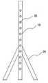
이러한 레이저 트랙커는 그 사용 전에 먼저 레이저 트랙커의 검교정이 이루어져야 한다. 그리고 검교정은 다양한 거리와 각도를 설정하여 작업이 이루어지는데, 도 9에 도시된 바와 같이 종래의 검교정용 장치를 살펴보면, 리플렉터가 안착되는 다수개의 어댑터(30)가 수직바(10) 상에 고정 설치되어 있고, 하단에는 다수개의 지지다리(20)가 설치되어 사용자가 이 검교정용 장치를 필요한 장소로 이동 설치하여 검교정 위치에 따라 각각의 어댑터(30)에 리플렉터를 설치하여 검교정 작업을 수행하도록 하고 있다.Such a laser tracker must first be calibrated with the laser tracker. And calibration is performed by setting a variety of distances and angles, as shown in the conventional calibration device as shown in Figure 9, a plurality of
이와 같은 종래의 레이저 트랙커는 단방향에 의한 거리측정에만 쓰이는 한계점이 있으며, 레이저 트랙커와 피측정 물체 사이에 제3의 물체가 있는 경우에는 측정을 할 수 없는 문제가 있다. 또한, 장비가 고가이고 설치비용 등이 과다하며, 검교정 과정이 복잡하다는 문제가 있다.
Such a conventional laser tracker has a limitation that is used only for distance measurement in one direction, and there is a problem in that a measurement cannot be performed when there is a third object between the laser tracker and the object under measurement. In addition, there is a problem that the equipment is expensive, the installation cost is excessive, and the calibration process is complicated.
따라서, 본 발명은 상기와 같은 종래기술의 문제점을 해결하기 위하여 안출된 것으로, 전파를 이용하여 두 물체 사이의 거리를 간편하게 측정할 수 있으며, 제3의 물체가 존재하더라도 측정할 수 있는 편의성을 제공하는 전파를 이용한 거리측정장치에 관한 것이다.
Accordingly, the present invention has been made to solve the above problems of the prior art, it is possible to easily measure the distance between the two objects by using radio waves, and provide a convenience that can be measured even if a third object exists It relates to a distance measuring device using a radio wave.
이를 위해 본 발명의 일 실시예에 따른 전파를 이용한 거리측정장치는 전파를 이용하여 두 물체 사이의 거리를 측정하고, 두 물체에 각각 장착되고, 무선통신을 통해 자신의 위치정보를 송신하는 한 쌍의 위치센서와 휴대가능하도록 구성되고, 상기 한 쌍의 위치센서로부터 위치정보를 수신하여 상기 두 물체 간의 거리를 산출 및 디스플레이하는 휴대용 거리측정 단말기를 포함하는 것을 특징으로 한다.To this end, a distance measuring apparatus using radio waves according to an embodiment of the present invention measures a distance between two objects by using radio waves, and is mounted on each of the two objects, and a pair for transmitting their location information through wireless communication. It is configured to be portable with a position sensor of the, characterized in that it comprises a portable distance measuring terminal for receiving the position information from the pair of position sensors to calculate and display the distance between the two objects.
또한, 본 발명에 따른 전파를 이용한 거리측정장치의 위치센서는 전파의 송수신 감도를 높이기 위해 투명 또는 반투명의 플라스틱 소재로 이루어지는 몸체와 상기 몸체에는 상기 휴대용 거리측정 단말기에서 송신하는 특정 주파수 대역에서 무선통신을 하는 통신부 및 상기 몸체의 일면에 형성되어 상기 물체에 고정되는 부착부를 포함하는 것을 특징으로 한다.In addition, the position sensor of the distance measuring apparatus using the radio wave according to the present invention has a body made of a transparent or semi-transparent plastic material to increase the transmission and reception sensitivity of the radio wave and the body has a wireless communication in a specific frequency band transmitted by the portable distance measuring terminal It is characterized in that it comprises a communication unit and an attachment portion formed on one surface of the body to be fixed to the object.
또한, 본 발명에 따른 전파를 이용한 거리측정장치의 휴대용 거리측정 단말기는 상기 두 물체 간의 거리정보를 요청할 수 있도록 구비되는 입력버튼과 사용자가 상기 입력버튼을 누르면 상기 한 쌍의 위치센서로 서로 다른 주파수 대역의 전파를 각각 송신하고, 상기 한 쌍의 위치센서로부터 위치정보를 수신하는 통신부와 상기 통신부에서 수신한 위치정보를 토대로 상기 두 물체 간의 거리를 산출하는 제어부 및 상기 제어부의 명령에 따라 산출된 두 물체 간의 거리를 시각적 또는 음성적으로 안내하는 디스플레이부를 포함하는 것을 특징으로 한다.In addition, the portable distance measuring terminal of the distance measuring apparatus using the radio wave according to the present invention is a frequency different from the input button and the pair of position sensors when the user presses the input button provided to request the distance information between the two objects; A control unit for transmitting a radio wave of a band, and receiving a position information from the pair of position sensors, and calculating a distance between the two objects based on the position information received from the communication unit, and two calculated according to the command of the control unit. It characterized in that it comprises a display unit for guiding the distance between the objects visually or voice.
또한, 본 발명에 따른 전파를 이용한 거리측정장치의 입력버튼은 상기 휴대용 거리측정 단말기와 각각의 물체와의 거리를 측정할 수 있도록 구비되는 제1입력버튼부 및 두 물체 간의 거리정보를 요청할 수 있도록 구비되는 제2입력버튼부를 포함하는 것을 특징으로 한다.In addition, the input button of the distance measuring apparatus using the radio wave according to the present invention, so as to request the distance information between the first input button unit and the two objects provided to measure the distance between the portable distance measuring terminal and each object. It characterized in that it comprises a second input button unit provided.
또한, 본 발명에 따른 전파를 이용한 거리측정장치의 휴대용 거리측정 단말기에서 한 쌍의 위치센서로 송신하는 전파는 각각 500~600kHz 및 800~900kHz 대역의 라디오파(RF, Radio Frequency)인 것을 특징으로 한다.In addition, the radio waves transmitted to the pair of position sensors in the portable ranging device of the distance measuring device using the radio wave according to the present invention is characterized in that the radio frequency (RF, Radio Frequency) of 500 ~ 600kHz and 800 ~ 900kHz band, respectively do.
또한, 본 발명에 따른 전파를 이용한 거리측정장치는 식별신호를 수신하여 위치정보를 산출하는 위치정보 제공수단과 상기 두 물체에 각각 장착되고, 상기 위치정보 제공수단으로 상기 자신의 위치를 확인할 수 있는 상기 식별신호 및 위치정보를 각각 송수신하며, 상기 수신된 위치정보를 특정 주파수 대역의 파장을 통해 송출하는 한 쌍의 위치센서 및 휴대가능하도록 구성되고, 상기 한 쌍의 위치센서로부터 위치정보를 수신하여 상기 두 물체 간의 거리를 산출 및 디스플레이하는 휴대용 거리측정 단말기를 포함하는 것을 특징으로 한다.In addition, the distance measuring apparatus using the radio wave according to the present invention is equipped with the position information providing means for receiving the identification signal to calculate the position information and the two objects, respectively, the position information providing means can identify the position of the own And a pair of position sensors for transmitting and receiving the identification signal and the position information, and transmitting the received position information through a wavelength of a specific frequency band, and being portable, and receiving position information from the pair of position sensors. It characterized in that it comprises a portable ranging terminal for calculating and displaying the distance between the two objects.
또한, 본 발명에 따른 전파를 이용한 거리측정장치의 위치정보 제공수단은 위성항법장치(GPS,Global Positioning System)인 것을 특징으로 한다.In addition, the position information providing means of the distance measuring apparatus using the radio wave according to the present invention is characterized in that the GPS (Global Positioning System).
또한, 본 발명에 따른 전파를 이용한 거리측정장치의 위치정보 제공수단은 소정 범위 내에 설치되어 상기 위치센서로부터 식별신호를 수신하는 복수의 고정단말기와, 상기 각각의 고정단말기로부터 수신한 식별신호를 분석해 산출된 각각의 위치센서에 대한 위치정보를 해당 위치센서로 송신하는 서버를 포함하는 것을 특징으로 한다.In addition, the position information providing means of the distance measuring apparatus using the radio wave according to the present invention is installed within a predetermined range and a plurality of fixed terminals for receiving the identification signal from the position sensor, and analyzes the identification signal received from each of the fixed terminals Characterized in that it comprises a server for transmitting the calculated position information for each position sensor to the corresponding position sensor.
또한, 본 발명에 따른 전파를 이용한 거리측정장치의 위치센서는 전파의 송수신 감도를 높이기 위해 투명 또는 반투명의 플라스틱 소재로 이루어지는 몸체와 상기 몸체에는 상기 휴대용 거리측정 단말기 및 위치정보 제공수단과 무선통신을 하는 통신부; 및 상기 몸체의 일면에 형성되어 상기 물체에 고정되는 부착부를 포함하는 것을 특징으로 한다.In addition, the position sensor of the distance measuring apparatus using the radio wave according to the present invention has a body made of a transparent or translucent plastic material and the body has a wireless communication with the portable distance measuring terminal and the position information providing means to increase the transmission and reception sensitivity of the radio wave A communication unit; And an attachment part formed on one surface of the body and fixed to the object.
또한, 본 발명에 따른 전파를 이용한 거리측정장치의 위치센서의 통신부는 상기 휴대용 거리측정 단말기로부터 수신하는 특정 주파수 대역의 전파를 통해 무선통신하는 제1통신부 및 상기 제1통신부의 주파수 대역과 다른 대역의 전파를 사용하여 상기 위치정보 제공수단과 무선통신하는 제2통신부를 포함하는 것을 특징으로 한다.
In addition, the communication unit of the position sensor of the distance measuring apparatus using the radio wave according to the present invention is a band different from the frequency band of the first communication unit and the first communication unit for wireless communication through the radio wave of a specific frequency band received from the portable distance measuring terminal It characterized in that it comprises a second communication unit for wireless communication with the location information providing means using the radio wave of the.
본 발명에 따른 전파를 이용한 거리측정장치에 의하면, 전파를 이용하여 두 물체 사이의 거리를 간편하게 측정할 수 있으며, 제3의 물체가 존재하더라도 측정할 수 있는 편의성을 제공하는 효과가 있다.
According to the distance measuring apparatus using the radio wave according to the present invention, it is possible to easily measure the distance between the two objects by using the radio wave, it has the effect of providing a convenience that can be measured even if a third object exists.
도 1은 본 발명의 일실시예에 따른 전파를 이용한 거리측정장치의 구성을 나타내는 블럭도이다.
도 2는 본 발명에 따른 위치센서를 도시하는 사시도이다.
도 3은 본 발명에 따른 위치센서의 구성을 나타내는 블럭도이다.
도 4는 본 발명에 따른 휴대용 거리측정 단말기를 도시하는 사시도이다.
도 5는 본 발명에 따른 휴대용 거리측정 단말기의 구성을 나타내는 블럭도이다.
도 6은 본 발명에 따른 위치정보 제공수단의 구성을 도시하는 블럭도이다.
도 7은 본 발명의 전파를 이용한 거리측정장치가 작동되는 모습을 도시하는 개략도이다.
도 8은 본 발명의 전파를 이용한 거리측정장치의 신호 흐름을 도시하는 도면이다.
도 9는 종래의 거리측정장치인 레이저 트랙커를 도시하는 도면이다.1 is a block diagram showing the configuration of a distance measuring apparatus using radio waves according to an embodiment of the present invention.
2 is a perspective view showing a position sensor according to the present invention.
3 is a block diagram showing the configuration of a position sensor according to the present invention.
4 is a perspective view showing a portable distance measuring terminal according to the present invention.
5 is a block diagram showing the configuration of a portable distance measuring terminal according to the present invention.
6 is a block diagram showing the configuration of the positional information providing means according to the present invention.
Figure 7 is a schematic diagram showing the operation of the distance measuring device using the radio wave of the present invention.
8 is a diagram illustrating a signal flow of a distance measuring device using radio waves of the present invention.
9 is a view showing a laser tracker which is a conventional distance measuring device.
이하, 첨부 도면을 참조하여 본 발명의 실시 예를 상세히 설명하면 다음과 같다.Hereinafter, embodiments of the present invention will be described in detail with reference to the accompanying drawings.
본 발명을 설명함에 있어서, 관련된 공지기능 혹은 구성에 대한 구체적인 설명이 본 발명의 요지를 불필요하게 흐릴 수 있다고 판단되는 경우 그 상세한 설명은 생략한다. 또한, 후술되는 용어들은 본 발명에서의 기능을 고려하여 정의된 용어들로서 이는 사용자, 운용자의 의도 또는 판례 등에 따라 달라질 수 있다. 그러므로 그 정의는 본 명세서 전반에 걸친 내용을 토대로 내려져야 할 것이다.
In the following description of the present invention, a detailed description of known functions and configurations incorporated herein will be omitted when it may make the subject matter of the present invention rather unclear. In addition, the terms described below are defined in consideration of the functions of the present invention, and these may vary depending on the intention of the user, the operator, or the precedent. Therefore, the definition should be based on the contents throughout this specification.
도 1은 본 발명의 일실시예에 따른 전파를 이용한 거리측정장치의 구성을 나타내는 블럭도이고, 도 2는 본 발명에 따른 위치센서를 도시하는 사시도이며, 도 3은 본 발명에 따른 위치센서의 구성을 나타내는 블럭도이다.1 is a block diagram showing a configuration of a distance measuring apparatus using radio waves according to an embodiment of the present invention, Figure 2 is a perspective view showing a position sensor according to the present invention, Figure 3 is a position sensor according to the present invention It is a block diagram which shows a structure.
그리고 도 4는 본 발명에 따른 휴대용 거리측정 단말기를 도시하는 사시도이고, 도 5는 본 발명에 따른 휴대용 거리측정 단말기의 구성을 나타내는 블럭도이며, 그리고 도 6은 본 발명에 따른 위치정보 제공수단의 구성을 도시하는 블럭도이다.4 is a perspective view showing a portable distance measuring terminal according to the present invention, FIG. 5 is a block diagram showing the configuration of the portable distance measuring terminal according to the present invention, and FIG. 6 is a view of the position information providing means according to the present invention. It is a block diagram showing a configuration.
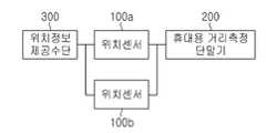
도 1을 참조하면, 본 실시예에 따른 전파를 이용한 거리측정장치는 기존의 레이저 트랙커와 달리 전파를 이용하여 두 물체 사이의 거리를 측정하는 것으로서, 한 쌍의 위치센서(100a,100b)와, 휴대용 거리측정 단말기(200) 및 위치정보 제공수단(300)을 포함한다.Referring to FIG. 1, unlike the conventional laser tracker, the distance measuring apparatus using the radio wave measures a distance between two objects using radio waves, and includes a pair of
구체적으로, 본 발명의 전파를 이용한 거리측정장치는 두 물체에 각각 장착되고, 무선통신을 통해 자신의 위치정보를 송신하는 한 쌍의 위치센서(100a,100b)와, 상기 한 쌍의 위치센서(100a,100b)로부터 식별신호를 수신하여 위치정보를 산출하는 위치정보 제공수단(300) 및 휴대가능하도록 구성되고, 상기 한 쌍의 위치센서(100a,100b)로부터 위치정보를 수신하여 상기 두 물체 간의 거리를 산출 및 디스플레이하는 휴대용 거리측정 단말기(200)를 포함한다.
Specifically, the distance measuring apparatus using the radio wave of the present invention is mounted on each of the two objects, a pair of position sensors (100a, 100b) for transmitting their position information through wireless communication, and the pair of position sensors ( A location
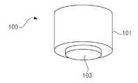
도 2 및 도 3을 참조하면, 본 발명에 따른 위치센서(100a,100b)는 거리 측정의 대상이 되는 두 물체에 각각 부착되어 위치정보를 상기 휴대용 거리측정 단말기(200)로 송신하는 역할을 하는 것으로서, 몸체(101)와 상기 몸체의 내부에 설치되는 통신부(120)와, 상기 통신부(120)의 송수신을 제어하는 제어부(110) 및 상기 몸체(101)의 일면에 고정되는 부착부(103)를 포함한다.2 and 3, the
상기 몸체(101)는 통신부(120)와 제어부(110)를 수용하는 것으로서, 본 실시예에서는 상기 몸체(101)가 원통 형상이고, 투명 또는 반투명의 플라스틱 소재인 것을 예시하였지만, 다양한 형상과 소재를 이용하여 구성할 수 있음은 물론이다.The
상기 통신부(120)는 자신의 위치를 확인할 수 있도록 식별신호 및 위치정보를 송신수신하는 역할을 한다.The
구체적으로, 상기 통신부(120)는 자신의 위치를 확인할 수 있는 식별신호를 지속적으로 송출하고, 상기 식별신호를 수신한 위치정보 제공수단으로부터 위치정보를 수신하여 이를 상기 휴대용 거리측정 단말기(200)로 송신한다. 이때, 상기 통신부(120)는 휴대용 거리측정 단말기(200)에서 위치정보를 요청하는 신호를 수신하는 경우에만 상기 위치정보 제공수단으로부터 수신한 위치정보를 휴대용 거리측정 단말기(200)로 송신하게 된다.Specifically, the
상기 위치센서(100a,100b)의 통신부(120)는 상기 휴대용 거리측정 단말기(200)로부터 수신하는 특정 주파수 대역의 전파를 통해 무선통신하는 제1통신부(121) 및 상기 제1통신부(121)의 주파수 대역과 다른 대역의 전파를 사용하여 상기 위치정보 제공수단(300)과 무선통신하는 제2통신부(122)를 포함하여 이루어질 수 있다.The
그리고 상기 제1통신부(121)는 휴대용 거리측정 단말기(200)와의 특정 주파수 대역의 전파를 통해 위치정보 요청 신호를 수신하고, 자신의 위치정보를 송신하게 된다.The
한편, 상기 제어부(110)는 상기 통신부(120)의 송수신을 전반적으로 제어하는 역할을 한다.
On the other hand, the
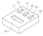
도 4 및 도 5를 참조하면, 본 발명에 따른 휴대용 거리측정 단말기(200)는 휴대가능하도록 배터리가 내장되도록 구성할 수 있고, 상기 한 쌍의 위치센서(100a,100b)로부터 위치정보를 수신하여 두 물체 간의 거리를 산출하고 디스플레이하는 역할을 한다.4 and 5, the portable
상기 휴대용 거리측정 단말기(200)는 두 물체 간의 거리정보를 요청할 수 있도록 구비되는 입력버튼(210)과, 사용자가 상기 입력버튼(210)을 누르면 상기 한 쌍의 위치센서(100a,100b)로 서로 다른 주파수 대역의 전파를 각각 송신하고, 상기 한 쌍의 위치센서(100a,100b)로부터 위치정보를 수신하는 통신부(230)와, 상기 통신부(230)에서 수신한 위치정보를 토대로 상기 두 물체 간의 거리를 산출하는 제어부(270) 및 상기 제어부(270)의 명령에 따라 산출된 두 물체 간의 거리를 시각적 또는 음성적으로 안내하는 디스플레이부(250)를 포함할 수 있다.The portable
상기 입력버튼(210)은 휴대용 거리측정 단말기(200)와 각각의 물체와의 거리를 측정할 수 있도록 구비되는 제1입력버튼부(211,212) 및 두 물체 간의 거리정보를 요청할 수 있도록 구비되는 제2입력버튼부(213)를 포함하여 구성할 수 있다.The
상기 휴대용 거리측정 단말기(200)에서는 제1입력버튼부(211,212)를 누름으로써, 위치센서(100a,100b)와의 거리를 측정할 수도 있다. 즉, 제1입력버튼부(211,212)를 누르는 간단한 동작만으로 물체(A 또는 B)와의 거리를 손쉽게 측정할 수 있으며, 거리 산출은 전파 이동 시간을 이용하는 것을 예시할 수 있다.In the portable
그리고 제1입력버튼부(211,212) 및 제2입력버튼부(213) 각각의 조작상태를 표시하는 LED 램프(200)를 형성할 수 있다. 예를 들어, 물체 A에 해당하는 제1입력버튼부(211)를 누르고, 물체 A와의 거리가 측정되면 LED 램프(221)가 켜지면서 거리측정이 완료되었음을 표시하고, 디스플레이부(250)에서는 그 거리 값을 안내하게 된다. 그리고 물체 A, B와의 거리를 측정하기 위해 제2입력버튼부(213)를 누르게 되면, 물체 A, B 각각에 대한 위치정보를 송신하도록 요청 신호를 송신하게 되고, 한 쌍의 위치센서(100a,100b)로부터 각각의 위치정보를 수신하게 되면 LED 램프(223)가 켜지면서, 디스플레이부(250)에서 A,B 사이의 거리 값이 디스플레이된다.In addition, the
상기 제어부(270)는 사용자가 입력버튼(210)을 통해 원하는 거리 또는 위치정보를 요청하게 되면 이를 통신부(230) 및 디스플레이부(250)에 전달하고 전반적으로 제어하는 역할을 한다.When the user requests the desired distance or location information through the
한편, 상기 통신부(230)에서 한 쌍의 위치센서(100a,100b)로 송신하는 전파는 각각 라디오파(RF, Radio Frequency)로 구성할 수 있으며, 각각의 위치센서로 송수신하는 주파수 대역이 서로 다르도록 예를 들어, 500~600kHz 및 800~900kHz 대역의 라디오파를 이용할 수 있다.
Meanwhile, the radio waves transmitted from the
도 6을 참조하면, 본 발명에 따른 위치정보 제공수단(300)은 위치센서(100a,100b)에서 송출하는 식별신호를 수신하여 각각의 위치센서(100a,100b)의 위치정보를 산출하게 된다.Referring to FIG. 6, the position
상기 위치정보 제공수단(300)은 위성항법장치(GPS,Global Positioning System)를 이용할 수도 있으며, 위성항법장치에 의해 위치센서의 위치 내지 위치정보를 확인하는 구성은 당업자에게 이미 공지된 사항에 해당하므로 그 자세한 설명은 생략한다.The position
또한, 위치정보 제공수단(300)은 소정 범위 내에 설치되어 상기 위치센서(100a,100b)로부터 식별신호를 수신하는 복수의 고정단말기(320)와, 상기 각각의 고정단말기(321,322,323,324)로부터 수신한 식별신호를 분석해 산출된 각각의 위치정보를 해당 위치센서(100a,100b)로 송신하는 서버(310)를 포함할 수 있다.In addition, the location
예를 들어, 상기 복수의 고정단말기(320) 각각은 소정 범위 내에 위치한 위치센서(100a,100b)의 식별신호를 수신하면 이를 서버(310)로 송신하게 된다. 그리고 서버(310)에서는 고정단말기(321,322,323,324)에서 수신한 식별신호에 대한 정보를 분석하여 위치센서의 위치정보를 산출하여 위치센서(100a,100b)로 송신하게 된다.
For example, each of the plurality of fixed
전술한 구성을 갖는 본 발명의 일 실시예에 따른 위치 조절 장치의 동작을 살펴보면 다음과 같다.Looking at the operation of the position adjusting device according to an embodiment of the present invention having the above-described configuration is as follows.
도 7은 본 발명의 전파를 이용한 거리측정장치가 작동되는 모습을 도시하는 개략도이고, 도 8은 본 발명의 전파를 이용한 거리측정장치의 신호 흐름을 도시하는 도면이다.7 is a schematic diagram showing the operation of the distance measuring device using the radio wave of the present invention, Figure 8 is a diagram showing the signal flow of the distance measuring device using the radio wave of the present invention.
도 7 및 도 8을 참조하면, 먼저 위치센서(100a,100b)에서는 근거리 무선통신 방식으로 자신의 위치를 확인할 수 있는 식별신호를 지속적으로 송신한다. 그리고 위치정보 제공수단(300)에서는 이 식별신호를 수신하고, 이를 위치센서(100a,100b)의 위치정보를 산출하여 전송하게 된다.Referring to FIGS. 7 and 8, first, the
다음으로, 위치정보 제공수단(300)으로부터 전송된 위치정보는 다시 위치센서(100a,100b)에서 수신하여 이를 휴대용 거리측정 단말기(200)로 전송하게 된다.Next, the position information transmitted from the position
상기 휴대용 거리측정 단말기(200)에서는 수신한 위치정보를 이용하여 A, B 물체 사이의 거리를 산출하고 디스플레이한다.
The portable
한편, 본 발명의 상세한 설명 및 첨부도면에서는 구체적인 실시예에 관해 설명하였으나, 본 발명은 개시된 실시예에 한정되지 않고 본 발명이 속하는 기술분야에서 통상의 지식을 가진 자에게 있어 본 발명의 기술적 사상을 벗어나지 않는 범위 내에서 여러 가지 치환, 변형 및 변경이 가능하다. 따라서, 본 발명의 범위는 설명된 실시예에 국한되어 정해져서는 안되며 후술하는 특허청구범위뿐만 아니라 이 특허청구범위와 균등한 것들을 포함하는 것으로 해석되어야 할 것이다.
While the present invention has been described in connection with what is presently considered to be practical exemplary embodiments, it is to be understood that the invention is not limited to the disclosed embodiments, but, on the contrary, It is to be understood that the invention is not limited to the disclosed embodiments, but, on the contrary, is intended to cover various modifications and similarities. Accordingly, the scope of the present invention should be construed as being limited to the embodiments described, and it is intended that the scope of the present invention encompasses not only the following claims, but also equivalents thereto.
100 : 위치센서101 : 몸체
103 : 부착부110 : 제어부
120 : 통신부121 : 제1통신부
122 : 제2통신부200 : 휴대용 거리측정 단말기
210 : 입력버튼211, 212 : 제1입력버튼부
213 : 제2입력버튼부220,221,222,223 : 램프
230 : 통신부250 : 디스플레이부
270 : 제어부300 : 위치정보 제공수단
310 : 서버320,321,322,323,324 : 고정단말기100: position sensor 101: body
103: attachment portion 110: control unit
120: communication unit 121: first communication unit
122: second communication unit 200: portable distance measuring terminal
210:
213: second
230: communication unit 250: display unit
270: control unit 300: location information providing means
310: server 320,321,322,323,324: fixed terminal
Claims (10)
Translated fromKorean상기 두 물체에 각각 장착되고, 무선통신을 통해 자신의 위치정보를 송신하는 한 쌍의 위치센서와;
휴대가능하도록 구성되고, 상기 한 쌍의 위치센서로부터 위치정보를 수신하여 상기 두 물체 간의 거리를 산출 및 디스플레이하는 휴대용 거리측정 단말기;
를 포함하는 것을 특징으로 하는 전파를 이용한 거리측정장치.
In the distance measuring device for measuring the distance between two objects using radio waves,
A pair of position sensors respectively mounted on the two objects and transmitting their position information through wireless communication;
A portable distance measuring terminal configured to be portable and configured to receive position information from the pair of position sensors to calculate and display a distance between the two objects;
Distance measuring device using a radio wave comprising a.
상기 위치센서는,
전파의 송수신 감도를 높이기 위해 플라스틱 소재로 이루어지는 몸체와;
상기 몸체에는 상기 휴대용 거리측정 단말기에서 송신하는 특정 주파수 대역에서 무선통신을 하는 통신부; 및
상기 몸체의 일면에 형성되어 상기 물체에 고정되는 부착부;
를 포함하는 것을 특징으로 하는 전파를 이용한 거리측정장치.
The method of claim 1,
The position sensor,
A body made of a plastic material to increase transmission and reception sensitivity of radio waves;
The body includes a communication unit for wireless communication in a specific frequency band transmitted by the portable distance measuring terminal; And
An attachment part formed on one surface of the body and fixed to the object;
Distance measuring device using a radio wave comprising a.
상기 휴대용 거리측정 단말기는,
상기 두 물체 간의 거리정보를 요청할 수 있도록 구비되는 입력버튼과;
사용자가 상기 입력버튼을 누르면 상기 한 쌍의 위치센서로 서로 다른 주파수 대역의 전파를 각각 송신하고, 상기 한 쌍의 위치센서로부터 위치정보를 수신하는 통신부와;
상기 통신부에서 수신한 위치정보를 토대로 상기 두 물체 간의 거리를 산출하는 제어부; 및
상기 제어부의 명령에 따라 산출된 두 물체 간의 거리를 시각적 또는 음성적으로 안내하는 디스플레이부;를 포함하는 것을 특징으로 하는 전파를 이용한 거리측정장치.
The method of claim 1,
The portable distance measuring terminal,
An input button provided to request distance information between the two objects;
A communication unit for transmitting radio waves of different frequency bands to the pair of position sensors when the user presses the input button, and receiving position information from the pair of position sensors;
A controller calculating a distance between the two objects based on the position information received by the communication unit; And
And a display unit for guiding the distance between two objects calculated in response to a command of the controller, visually or voicely.
상기 입력버튼은 상기 휴대용 거리측정 단말기와 각각의 물체와의 거리를 측정할 수 있도록 구비되는 제1입력버튼부 및 두 물체 간의 거리정보를 요청할 수 있도록 구비되는 제2입력버튼부를 포함하는 것을 특징으로 하는 전파를 이용한 거리측정장치.
The method of claim 3,
The input button may include a first input button unit provided to measure a distance between the portable distance measuring terminal and each object and a second input button unit provided to request distance information between two objects. Distance measuring device using radio waves.
상기 휴대용 거리측정 단말기에서 한 쌍의 위치센서로 송신하는 전파는 각각 500~600kHz 및 800~900kHz 대역의 라디오파(RF, Radio Frequency)인 것을 특징으로 하는 전파를 이용한 거리측정장치.
The method of claim 3,
The radio wave transmitted from the portable distance measuring terminal to the pair of position sensors is a radio wave (RF, Radio Frequency) in the band 500 ~ 600kHz and 800 ~ 900kHz, respectively.
식별신호를 수신하여 위치정보를 산출하는 위치정보 제공수단과;
상기 두 물체에 각각 장착되고, 상기 위치정보 제공수단으로 상기 자신의 위치를 확인할 수 있는 상기 식별신호 및 위치정보를 각각 송수신하며, 상기 수신된 위치정보를 특정 주파수 대역의 파장을 통해 송출하는 한 쌍의 위치센서; 및
휴대가능하도록 구성되고, 상기 한 쌍의 위치센서로부터 위치정보를 수신하여 상기 두 물체 간의 거리를 산출 및 디스플레이하는 휴대용 거리측정 단말기;
를 포함하는 것을 특징으로 하는 전파를 이용한 거리측정장치.
In the distance measuring device for measuring the distance between two objects using radio waves,
Location information providing means for receiving an identification signal and calculating location information;
A pair mounted on each of the two objects and transmitting and receiving the identification signal and the position information, respectively, to identify the position thereof by the position information providing means, and transmitting the received position information through a wavelength of a specific frequency band. Position sensor; And
A portable distance measuring terminal configured to be portable and configured to receive position information from the pair of position sensors to calculate and display a distance between the two objects;
Distance measuring device using a radio wave comprising a.
상기 위치정보 제공수단은 위성항법장치(GPS,Global Positioning System)인 것을 특징으로 하는 전파를 이용한 거리측정장치.
The method according to claim 6,
The position information providing means is a satellite navigation device (GPS, Global Positioning System) characterized in that the radio wave using a distance measuring apparatus.
상기 위치정보 제공수단은,
소정 범위 내에 설치되어 상기 위치센서로부터 식별신호를 수신하는 복수의 고정단말기와,
상기 각각의 고정단말기로부터 수신한 식별신호를 분석해 산출된 각각의 위치센서에 대한 위치정보를 해당 위치센서로 송신하는 서버;
를 포함하는 것을 특징으로 하는 전파를 이용한 거리측정장치.
The method according to claim 6,
The location information providing means,
A plurality of fixed terminals installed within a predetermined range and receiving an identification signal from the position sensor;
A server for analyzing the identification signal received from each fixed terminal and transmitting the position information of each position sensor to the corresponding position sensor;
Distance measuring device using a radio wave comprising a.
상기 위치센서는,
전파의 송수신 감도를 높이기 위해 투명 또는 반투명의 플라스틱 소재로 이루어지는 몸체와; 상기 몸체에 수용되고 상기 휴대용 거리측정 단말기 및 위치정보 제공수단과 무선통신을 하는 통신부; 및 상기 몸체의 일면에 형성되어 상기 물체에 고정되는 부착부;를 포함하는 것을 특징으로 하는 전파를 이용한 거리측정장치.
The method according to claim 6,
The position sensor,
A body made of transparent or translucent plastic material to increase the transmission and reception sensitivity of radio waves; A communication unit accommodated in the body and performing wireless communication with the portable distance measuring terminal and the location information providing means; And an attachment part formed on one surface of the body and fixed to the object.
상기 위치센서의 통신부는,
상기 휴대용 거리측정 단말기로부터 수신하는 특정 주파수 대역의 전파를 통해 무선통신하는 제1통신부; 및 상기 제1통신부의 주파수 대역과 다른 대역의 전파를 사용하여 상기 위치정보 제공수단과 무선통신하는 제2통신부;를 포함하는 것을 특징으로 하는 전파를 이용한 거리측정장치.10. The method of claim 9,
The communication unit of the position sensor,
A first communication unit performing wireless communication through radio waves of a specific frequency band received from the portable distance measuring terminal; And a second communication unit wirelessly communicating with the location information providing means by using radio waves in a band different from a frequency band of the first communication unit.
Priority Applications (1)
| Application Number | Priority Date | Filing Date | Title |
|---|---|---|---|
| KR1020120088819AKR101295495B1 (en) | 2012-08-14 | 2012-08-14 | Distance measuring device using radio waves |
Applications Claiming Priority (1)
| Application Number | Priority Date | Filing Date | Title |
|---|---|---|---|
| KR1020120088819AKR101295495B1 (en) | 2012-08-14 | 2012-08-14 | Distance measuring device using radio waves |
Publications (1)
| Publication Number | Publication Date |
|---|---|
| KR101295495B1true KR101295495B1 (en) | 2013-08-09 |
Family
ID=49220323
Family Applications (1)
| Application Number | Title | Priority Date | Filing Date |
|---|---|---|---|
| KR1020120088819AExpired - Fee RelatedKR101295495B1 (en) | 2012-08-14 | 2012-08-14 | Distance measuring device using radio waves |
Country Status (1)
| Country | Link |
|---|---|
| KR (1) | KR101295495B1 (en) |
Citations (4)
| Publication number | Priority date | Publication date | Assignee | Title |
|---|---|---|---|---|
| KR20090110839A (en)* | 2006-12-27 | 2009-10-22 | 트루포지션, 인크. | Mobile, Repeated Geolocation of RF Radiators |
| KR20110083223A (en)* | 2010-01-14 | 2011-07-20 | 주식회사 엘지유플러스 | Location information collection method for using GPS information and mobile communication terminal for location information collection |
| KR20120034771A (en)* | 2009-09-28 | 2012-04-12 | 가부시키가이샤 히타치세이사쿠쇼 | Positional information transmitter, communication terminal, and positioning system |
| JP2012509652A (en) | 2008-11-21 | 2012-04-19 | クアルコム,インコーポレイテッド | Wireless-based positioning adjustment using motion sensor |
- 2012
- 2012-08-14KRKR1020120088819Apatent/KR101295495B1/ennot_activeExpired - Fee Related
Patent Citations (4)
| Publication number | Priority date | Publication date | Assignee | Title |
|---|---|---|---|---|
| KR20090110839A (en)* | 2006-12-27 | 2009-10-22 | 트루포지션, 인크. | Mobile, Repeated Geolocation of RF Radiators |
| JP2012509652A (en) | 2008-11-21 | 2012-04-19 | クアルコム,インコーポレイテッド | Wireless-based positioning adjustment using motion sensor |
| KR20120034771A (en)* | 2009-09-28 | 2012-04-12 | 가부시키가이샤 히타치세이사쿠쇼 | Positional information transmitter, communication terminal, and positioning system |
| KR20110083223A (en)* | 2010-01-14 | 2011-07-20 | 주식회사 엘지유플러스 | Location information collection method for using GPS information and mobile communication terminal for location information collection |
Similar Documents
| Publication | Publication Date | Title |
|---|---|---|
| US10415950B2 (en) | Metrology device and method of performing an inspection | |
| US9803969B2 (en) | Metrology device and method of communicating with portable devices | |
| US9921046B2 (en) | Metrology device and method of servicing | |
| CN113794982B (en) | Storage medium position detection system and program | |
| US20150330765A1 (en) | Articulated arm coordinate measurement machine having a rotary switch | |
| US20150330766A1 (en) | Metrology device and method of changing operating system | |
| US20150330762A1 (en) | Metrology device and method of initiating communication | |
| US9212889B2 (en) | Apparatus for pointing spatial coordinates, comprising a movable hand-held probe and a portable base unit, and a related method | |
| KR100790084B1 (en) | Method and device for measuring distance of Bluetooth terminal | |
| CN101566528A (en) | Parameter detection system | |
| KR20150114106A (en) | The plant field operators outfit for plant operation by using augmented reality and the method for providing information for plant operator | |
| EP4102178A1 (en) | Vehicle service system and operating method thereof | |
| JPH10282204A (en) | Mobile object position detection equipment | |
| JP2018515754A (en) | POSITION INFORMATION PROVIDING DEVICE AND NODE NETWORK | |
| US20130162971A1 (en) | Optical system | |
| KR101295495B1 (en) | Distance measuring device using radio waves | |
| KR101239337B1 (en) | Apparatus for noncontact measurement | |
| US20190011527A1 (en) | Position detection system | |
| US20210080257A1 (en) | Survey pole with indicia for automatic tracking | |
| KR20170140009A (en) | Target position detection apparatus and distance, area, volume measuring devices | |
| US20170136952A1 (en) | Electronic compass device for vehicle, portable electronic compass calibration device, control program for portable electronic compass calibration device, and electronic compass calibration system for vehicle | |
| JP2015013330A5 (en) | Device with robot arm | |
| US9267794B2 (en) | Method of determining a target spatial coordinate using an apparatus comprising a movable hand-held probe and a portable base unit, and a related apparatus | |
| US12196554B2 (en) | Integrated GNSS and optical system | |
| KR20170101343A (en) | Parking position checking apparatus using mobile communication device and method thereof |
Legal Events
| Date | Code | Title | Description |
|---|---|---|---|
| A201 | Request for examination | ||
| PA0109 | Patent application | St.27 status event code:A-0-1-A10-A12-nap-PA0109 | |
| PA0201 | Request for examination | St.27 status event code:A-1-2-D10-D11-exm-PA0201 | |
| D13-X000 | Search requested | St.27 status event code:A-1-2-D10-D13-srh-X000 | |
| D14-X000 | Search report completed | St.27 status event code:A-1-2-D10-D14-srh-X000 | |
| E701 | Decision to grant or registration of patent right | ||
| PE0701 | Decision of registration | St.27 status event code:A-1-2-D10-D22-exm-PE0701 | |
| GRNT | Written decision to grant | ||
| PR0701 | Registration of establishment | St.27 status event code:A-2-4-F10-F11-exm-PR0701 | |
| PR1002 | Payment of registration fee | Fee payment year number:1 St.27 status event code:A-2-2-U10-U11-oth-PR1002 | |
| PG1601 | Publication of registration | St.27 status event code:A-4-4-Q10-Q13-nap-PG1601 | |
| LAPS | Lapse due to unpaid annual fee | ||
| PC1903 | Unpaid annual fee | Not in force date:20160806 Payment event data comment text:Termination Category : DEFAULT_OF_REGISTRATION_FEE St.27 status event code:A-4-4-U10-U13-oth-PC1903 | |
| P22-X000 | Classification modified | St.27 status event code:A-4-4-P10-P22-nap-X000 | |
| PC1903 | Unpaid annual fee | Ip right cessation event data comment text:Termination Category : DEFAULT_OF_REGISTRATION_FEE Not in force date:20160806 St.27 status event code:N-4-6-H10-H13-oth-PC1903 | |
| P22-X000 | Classification modified | St.27 status event code:A-4-4-P10-P22-nap-X000 | |
| PN2301 | Change of applicant | St.27 status event code:A-5-5-R10-R11-asn-PN2301 St.27 status event code:A-5-5-R10-R13-asn-PN2301 | |
| PN2301 | Change of applicant | St.27 status event code:A-5-5-R10-R11-asn-PN2301 St.27 status event code:A-5-5-R10-R13-asn-PN2301 |