KR101292958B1 - Holding Apparatus for Medical Tube - Google Patents
Holding Apparatus for Medical TubeDownload PDFInfo
- Publication number
- KR101292958B1 KR101292958B1KR1020110130912AKR20110130912AKR101292958B1KR 101292958 B1KR101292958 B1KR 101292958B1KR 1020110130912 AKR1020110130912 AKR 1020110130912AKR 20110130912 AKR20110130912 AKR 20110130912AKR 101292958 B1KR101292958 B1KR 101292958B1
- Authority
- KR
- South Korea
- Prior art keywords
- fixing
- attachment
- tube
- coupling
- nose
- Prior art date
- Legal status (The legal status is an assumption and is not a legal conclusion. Google has not performed a legal analysis and makes no representation as to the accuracy of the status listed.)
- Expired - Fee Related
Links
Images


Classifications
- A—HUMAN NECESSITIES
- A61—MEDICAL OR VETERINARY SCIENCE; HYGIENE
- A61M—DEVICES FOR INTRODUCING MEDIA INTO, OR ONTO, THE BODY; DEVICES FOR TRANSDUCING BODY MEDIA OR FOR TAKING MEDIA FROM THE BODY; DEVICES FOR PRODUCING OR ENDING SLEEP OR STUPOR
- A61M25/00—Catheters; Hollow probes
- A61M25/01—Introducing, guiding, advancing, emplacing or holding catheters
- A61M25/02—Holding devices, e.g. on the body
- A—HUMAN NECESSITIES
- A61—MEDICAL OR VETERINARY SCIENCE; HYGIENE
- A61M—DEVICES FOR INTRODUCING MEDIA INTO, OR ONTO, THE BODY; DEVICES FOR TRANSDUCING BODY MEDIA OR FOR TAKING MEDIA FROM THE BODY; DEVICES FOR PRODUCING OR ENDING SLEEP OR STUPOR
- A61M35/00—Devices for applying media, e.g. remedies, on the human body
- A—HUMAN NECESSITIES
- A61—MEDICAL OR VETERINARY SCIENCE; HYGIENE
- A61M—DEVICES FOR INTRODUCING MEDIA INTO, OR ONTO, THE BODY; DEVICES FOR TRANSDUCING BODY MEDIA OR FOR TAKING MEDIA FROM THE BODY; DEVICES FOR PRODUCING OR ENDING SLEEP OR STUPOR
- A61M25/00—Catheters; Hollow probes
- A61M25/01—Introducing, guiding, advancing, emplacing or holding catheters
- A61M25/02—Holding devices, e.g. on the body
- A61M2025/0213—Holding devices, e.g. on the body where the catheter is attached by means specifically adapted to a part of the human body
- A61M2025/0226—Holding devices, e.g. on the body where the catheter is attached by means specifically adapted to a part of the human body specifically adapted for the nose
- A—HUMAN NECESSITIES
- A61—MEDICAL OR VETERINARY SCIENCE; HYGIENE
- A61M—DEVICES FOR INTRODUCING MEDIA INTO, OR ONTO, THE BODY; DEVICES FOR TRANSDUCING BODY MEDIA OR FOR TAKING MEDIA FROM THE BODY; DEVICES FOR PRODUCING OR ENDING SLEEP OR STUPOR
- A61M2210/00—Anatomical parts of the body
- A61M2210/06—Head
- A61M2210/0618—Nose
Landscapes
- Health & Medical Sciences (AREA)
- Life Sciences & Earth Sciences (AREA)
- Animal Behavior & Ethology (AREA)
- Engineering & Computer Science (AREA)
- Anesthesiology (AREA)
- Biomedical Technology (AREA)
- Heart & Thoracic Surgery (AREA)
- Hematology (AREA)
- General Health & Medical Sciences (AREA)
- Public Health (AREA)
- Veterinary Medicine (AREA)
- Pulmonology (AREA)
- Biophysics (AREA)
- Media Introduction/Drainage Providing Device (AREA)
Abstract
Translated fromKoreanDescription
Translated fromKorean본 발명은 의료 분야에서 사용되는 튜브를 고정하기 위한 의료용 튜브 고정장치에 관한 것이다.The present invention relates to a medical tube holding device for fixing a tube used in the medical field.
여러 의료 분야에 있어서 레빈 튜브(Levin Tube) 등과 같은 의료용 튜브(Tube)가 사용된다. 예컨대, 위(胃)로부터 체액과 가스를 제거하여 감압하기 위한 경우, 수술 또는 외상 후에 위의 압력을 감소시켜 오심과 구토를 예방하거나 경감하기 위한 경우, 위장관(胃腸管) 수술 전후, 위장관의 운동기능 진단, 위의 심한 출혈 또는 독성을 세척하기 위한 경우, 장(腸)의 기계적 폐색을 치료하기 위한 경우, 약물을 투여하고 위장관으로 직접 영양(Gavage)을 공급하기 위한 경우, 유문 또는 장폐색이 의심될 때 검사를 위해 표본 채취를 하기 위한 경우 등에 의료용 튜브가 사용될 수 있다. 이러한 의료용 튜브는 일측이 위, 대장 등과 같은 위장관에 위치되고, 타측이 코를 통해 신체 외부에 위치된다.In many medical fields, medical tubes such as Levin tubes are used. For example, to remove body fluids and gases from the stomach and to reduce the pressure, to reduce or reduce the pressure of the stomach after surgery or trauma, to prevent or alleviate nausea and vomiting. Pylori or bowel obstruction is suspected for diagnosing the function, for cleaning the stomach severe bleeding or toxicity, for treating the mechanical obstruction of the intestine, for administering drugs and for feeding the nutrient directly into the gastrointestinal tract. Medical tubes may be used, for example, to take samples for examination. The medical tube is one side is located in the gastrointestinal tract, such as the stomach, colon, etc., the other side is located outside the body through the nose.
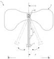
도 1은 종래 기술에 따라 의료용 튜브를 고정한 상태를 나타낸 도면이다.1 is a view showing a state in which the medical tube is fixed according to the prior art.
도 1을 참고하면, 종래에는 코를 통해 신체 외부에 위치한 튜브(10)를 반창고로 반복적으로 감은 후에 코에 부착함으로써 고정하였다. 이에 따라, 종래 기술에 따른 의료용 튜브 고정방법은 다음과 같은 문제가 있다.Referring to FIG. 1, conventionally, a
첫째, 종래 기술에 따른 의료용 튜브 고정방법은 반창고로 튜브(10)를 반복적으로 감은 후에 반창고의 남는 부분을 코에 부착하고, 결합력을 보강하기 위해 추가로 반창고를 덧대어 부착함으로써 튜브(10)를 고정하였다. 이에 따라, 종래 기술에 따른 의료용 튜브 고정방법은 튜브(10)를 고정하는 작업이 번거롭고, 튜브(10)를 고정하는 과정에서 환자에게 불편을 야기하게 되는 문제가 있다. 또한, 종래 기술에 따른 의료용 튜브 고정방법은 반창고가 튜브(10)에 반복적으로 감겨져 있어 외관상 보기에 좋지 못하고, 이로 인해 환자의 심리적 안정성을 저하시키는 문제가 있다.First, the method for fixing a medical tube according to the prior art wound the
둘째, 종래 기술에 따른 의료용 튜브 고정방법은 튜브(10)가 반창고에 고정되어 있기 때문에, 이동 범위가 상당히 제한적이다. 이에 따라, 환자가 옆으로 눕는 등 환자의 자세가 변경되는 경우에도, 튜브(10)가 반창고에 고정되어 이동하지 않기 때문에 튜브(10)가 반창고를 당기게 됨으로써, 환자에게 고통과 불편을 야기하게 되는 문제가 있다.Second, the medical tube fixing method according to the prior art, because the
본 발명의 배경이 되는 기술은 미국 특허공보 제4932943호(1990.06.12)에 개시되어 있다.Background art of the present invention is disclosed in US Patent No. 4932943 (June 12, 1990).
본 발명은 상술한 바와 같은 문제점을 해결하고자 안출된 것으로, 본 발명의 목적은 간단한 작업으로 튜브를 고정할 수 있는 의료용 튜브 고정장치를 제공하기 위한 것이다.The present invention has been made to solve the above problems, an object of the present invention is to provide a medical tube fixing device that can fix the tube in a simple operation.
본 발명의 다른 목적은 환자의 상태에 따라 튜브로 인해 환자에게 가해지는 부담을 줄일 수 있고, 이에 따라 환자에게 고통과 불편을 야기하는 것을 방지할 수 있는 의료용 튜브 고정장치를 제공하기 위한 것이다.Another object of the present invention is to provide a medical tube fixing device that can reduce the burden on the patient due to the tube according to the condition of the patient, thereby preventing the patient from causing pain and discomfort.
상술한 바와 같은 목적을 달성하기 위해서, 본 발명은 하기와 같은 구성을 포함할 수 있다.In order to achieve the above-mentioned object, the present invention can include the following configuration.
본 발명에 따른 의료용 튜브 고정장치는 코로부터 돌출된 튜브(Tube)를 고정하기 위한 고정부; 상기 고정부에 고정된 튜브를 지지하기 위해 피부에 부착되기 위한 부착부; 및 일측이 상기 고정부에 결합되고, 타측이 상기 부착부에 결합되는 연결부를 포함할 수 있다.Medical tube fixing device according to the invention the fixing portion for fixing the tube (Tube) protruding from the nose; An attachment portion for attaching to the skin to support the tube fixed to the fixing portion; And one side may be coupled to the fixing portion, the other side may include a connecting portion coupled to the attachment portion.
본 발명에 따르면, 다음과 같은 효과를 도모할 수 있다.According to the present invention, the following effects can be achieved.
본 발명은 간단한 작업으로 튜브를 고정할 수 있도록 구현됨으로써, 튜브를 고정하기 위한 작업의 용이성과 편의성을 향상시킬 수 있고, 튜브를 고정하는 과정에서 환자에게 가해지는 불편을 줄일 수 있다.The present invention is implemented to fix the tube by a simple operation, it is possible to improve the ease and convenience of the operation for fixing the tube, it is possible to reduce the inconvenience to the patient in the process of fixing the tube.
본 발명은 튜브를 고정하는 작업에 걸리는 시간을 줄일 수 있고, 이에 따라 튜브를 고정하는 작업을 수행하는 시술자와 환자 모두에게 편리함을 제공할 수 있다.The present invention can reduce the time taken to fix the tube, thereby providing convenience to both the operator and the patient performing the operation of fixing the tube.
본 발명은 코에 튜브가 삽입되어 고정되고 난 후에 환자의 외관을 향상시킬 수 있고, 이에 따라 환자의 심리적 안정성을 향상시키는데 기여할 수 있다.The present invention can improve the appearance of the patient after the tube is inserted and fixed in the nose, thereby contributing to improving the psychological stability of the patient.
도 1은 종래 기술에 따라 의료용 튜브를 고정한 상태를 나타낸 도면
도 2는 본 발명에 따른 의료용 튜브 고정장치의 개략적인 사시도
도 3은 본 발명에 따른 의료용 튜브 고정장치가 사용된 상태를 나타낸 개략적인 측면도
도 4 및 도 5는 본 발명에 따른 고정부에 대한 도 2의 I-I 선을 기준으로 한 단면도
도 6은 본 발명에 따른 의료용 튜브 고정장치의 개략적인 정면도
도 7은 도 6의 Ⅱ-Ⅱ 선을 기준으로 한 본 발명에 따른 의료용 튜브 고정장치의 개략적인 결합 단면도
도 8은 도 6의 Ⅱ-Ⅱ 선을 기준으로 한 본 발명에 따른 의료용 튜브 고정장치의 개략적인 분해 단면도
도 9는 본 발명에 따른 부착부에 대한 개략적인 분해 사시도1 is a view showing a state in which the medical tube fixed according to the prior art
Figure 2 is a schematic perspective view of the medical tube holding device according to the present invention
Figure 3 is a schematic side view showing a state in which a medical tube fixing device according to the invention is used
4 and 5 are cross-sectional views based on line II of FIG. 2 for the fixing part according to the present invention.
Figure 6 is a schematic front view of a medical tube holding device according to the present invention
Figure 7 is a schematic cross-sectional view of the medical tube holding device according to the present invention based on the line II-II of Figure 6
Figure 8 is a schematic exploded cross-sectional view of the medical tube holding device according to the present invention based on line II-II of Figure 6
9 is a schematic exploded perspective view of the attachment portion according to the present invention;
이하에서는 본 발명에 따른 의료용 튜브 고정장치의 바람직한 실시예를 첨부된 도면을 참조하여 상세히 설명한다.Hereinafter, with reference to the accompanying drawings a preferred embodiment of the medical tube fixing device according to the present invention will be described in detail.
도 2는 본 발명에 따른 의료용 튜브 고정장치의 개략적인 사시도, 도 3은 본 발명에 따른 의료용 튜브 고정장치가 사용된 상태를 나타낸 개략적인 측면도, 도 4 및 도 5는 본 발명에 따른 고정부에 대한 도 2의 I-I 선을 기준으로 한 단면도, 도 6은 본 발명에 따른 의료용 튜브 고정장치의 개략적인 정면도, 도 7은 도 6의 Ⅱ-Ⅱ 선을 기준으로 한 본 발명에 따른 의료용 튜브 고정장치의 개략적인 결합 단면도, 도 8은 도 6의 Ⅱ-Ⅱ 선을 기준으로 한 본 발명에 따른 의료용 튜브 고정장치의 개략적인 분해 단면도, 도 9는 본 발명에 따른 부착부에 대한 개략적인 분해 사시도이다.Figure 2 is a schematic perspective view of a medical tube fixing device according to the present invention, Figure 3 is a schematic side view showing a state in which the medical tube fixing device according to the invention is used, Figures 4 and 5 is a fixing part according to the
도 2 및 도 3을 참고하면, 본 발명에 따른 의료용 튜브 고정장치(1)는 튜브(10, 도 3에 도시됨)를 고정하기 위한 것이다. 상기 튜브(10)는 여러 의료 분야에 사용되는 것으로, 예컨대 레빈 튜브(Levin Tube)일 수 있다. 상기 튜브(10)는 위(胃)로부터 체액과 가스를 제거하여 감압하기 위한 경우, 수술 또는 외상 후에 위의 압력을 감소시켜 오심과 구토를 예방하거나 경감하기 위한 경우, 위장관(胃腸管) 수술 전후, 위장관의 운동기능 진단, 위의 심한 출혈 또는 독성을 세척하기 위한 경우, 장(腸)의 기계적 폐색을 치료하기 위한 경우, 약물을 투여하고 위장관으로 직접 영양(Gavage)을 공급하기 위한 경우, 유문 또는 장폐색이 의심될 때 검사를 위해 표본 채취를 하기 위한 경우 등에 사용될 수 있다. 이러한 튜브(10)는 일측이 위, 대장 등과 같은 위장관에 위치되고, 타측이 코(100, 도 3에 도시됨)를 통해 신체 외부에 위치된다.2 and 3, the medical
도 2 및 도 3을 참고하면, 본 발명에 따른 의료용 튜브 고정장치(1)는 코(100)로부터 돌출된 튜브(10)를 고정하기 위한 고정부(2), 상기 고정부(2)에 결합된 연결부(3), 및 상기 고정부(2)에 고정된 튜브(10)를 지지하기 위해 피부에 부착되기 위한 부착부(4)를 포함한다. 상기 연결부(3)는 상기 고정부(2)와 상기 부착부(4)를 연결한다. 상기 연결부(3)는 일측이 상기 고정부(2)에 결합되고, 타측이 상기 부착부(4)에 결합된다. 본 발명에 따른 의료용 튜브 고정장치(1)는 상기 부착부(4)가 피부에 부착된 후, 코(100)로부터 돌출된 튜브(10)가 상기 고정부(2)에 고정됨으로써, 튜브(10)를 고정할 수 있다. 따라서, 본 발명에 따른 의료용 튜브 고정장치(1)는 다음과 같은 작용효과를 도모할 수 있다.2 and 3, the medical
첫째, 종래에는 반창고로 튜브(10)를 반복적으로 감은 후에 반창고의 남는 부분을 코에 부착하고, 결합력을 보강하기 위해 추가로 반창고를 덧대어 부착함으로써 튜브(10)를 고정하였다. 이와 달리, 본 발명에 따른 의료용 튜브 고정장치(1)는 상기 부착부(4)가 피부에 부착된 후, 코(100)로부터 돌출된 튜브(10)가 상기 고정부(2)에 고정됨으로써, 튜브(10)를 고정할 수 있다. 따라서, 본 발명에 따른 의료용 튜브 고정장치(1)는, 종래 기술과 비교할 때 간단한 작업으로 튜브(10)를 고정할 수 있고, 이에 따라 튜브(10)를 고정하는 과정에서 환자에게 가해지는 불편을 줄일 수 있다.First, after the
둘째, 본 발명에 따른 의료용 튜브 고정장치(1)는, 종래 기술과 같이 반창고로 튜브(10)를 반복적으로 감을 필요가 없으므로, 튜브(10)를 고정하는 작업에 걸리는 시간을 줄일 수 있다. 따라서, 본 발명에 따른 의료용 튜브 고정장치(1)는 튜브(10)를 고정하는 작업을 수행하는 시술자와 환자 모두에게 편리함을 제공할 수 있다.Second, since the medical
셋째, 본 발명에 따른 의료용 튜브 고정장치(1)는 종래 기술과 같이 반창고로 튜브(10)를 반복적으로 감을 필요가 없으므로, 종래 기술과 비교할 때 튜브(10)를 고정하고 난 후에 환자의 외관을 향상시킬 수 있다. 따라서, 본 발명에 따른 의료용 튜브 고정장치(1)는 환자의 심리적 안정성을 향상시키는데 기여할 수 있다.Third, since the medical
이하에서는 상기 고정부(2), 상기 연결부(3) 및 상기 부착부(4)에 관해 첨부된 도면을 참조하여 구체적으로 설명한다.Hereinafter, the
도 2 내지 도 4를 참고하면, 상기 고정부(2)는 코(100, 도 3에 도시됨)로부터 돌출된 튜브(10, 도 3에 도시됨)를 고정한다. 상기 튜브(10)는 상기 고정부(2)를 통과하여 의료기기(미도시)에 결합된다. 상기 튜브(10)는 상기 고정부(2)에 삽입된 부분에 의해 상기 고정부(2)에 고정된다. 상기 고정부(2)는 전체적으로 원형 고리 형태로 형성될 수 있으나, 이에 한정되지 않으며 상기 튜브(10)를 고정할 수 있는 형태이면 다른 형태로 형성될 수도 있다.2 to 4, the
도 4를 참고하면, 상기 고정부(2)는 상기 튜브(10)가 삽입되기 위한 삽입공(21)을 포함한다. 상기 삽입공(21)은 상기 튜브(10)의 외경(External Diameter)(11)과 대략 일치하는 크기를 갖도록 형성된다. 상기 삽입공(21)은 상기 튜브(10)의 외경(11)과 대략 일치하는 직경을 갖는 원통 형태로 형성될 수 있다. 상기 튜브(10)는 내경(Internal Diameter)(12)의 크기에 따라 여러 종류로 이루어질 수 있다. 예컨대, 상기 튜브(10)는 종류에 따라 1.6 mm, 2.7 mm, 3.1 mm, 3.5 mm, 4.1 mm, 4.3 mm 등의 내경(12)을 갖도록 형성될 수 있다. 상기 튜브(10)는 수술의 종류, 수술 부위, 환자의 나이, 환자의 신체 크기 등의 사용 환경에 따라 내경(12)이 다른 것을 사용할 수 있다. 상기 튜브(10)는 내경(12)의 크기에 따라 외경(11)의 크기가 달라질 수 있다. 사용자는 사용 환경에 따라 그에 적합한 내경(12)을 갖는 튜브(10)를 선택하고, 본 발명에 따른 의료용 튜브 고정장치(1)가 갖는 삽입공(21)의 직경이 선택된 튜브(10)의 외경(11)과 대응되는 것을 선택하여 사용할 수 있다.Referring to FIG. 4, the
도 4를 참고하면, 상기 고정부(2)는 상기 삽입공(21) 쪽으로 돌출되게 형성된 돌기(22)를 포함한다. 상기 돌기(22)는 상기 고정부(2)에서 상기 삽입공(21)이 형성된 내면으로부터 돌출되게 형성될 수 있다. 상기 돌기(22)는 상기 삽입공(21)에 삽입된 튜브(10)를 가압할 수 있다. 따라서, 본 발명에 따른 의료용 튜브 고정장치(1)는 상기 돌기(22)가 상기 튜브(10)를 가압함으로써, 상기 튜브(10)를 상기 고정부(2)에 더 견고하게 고정할 수 있다. 또한, 본 발명에 따른 의료용 튜브 고정장치(1)는 상기 돌기(22)로 인해 상기 삽입공(21)의 크기보다 작은 크기를 갖는 튜브(10)를 고정하는 것이 가능하다. 따라서, 사용자는 사용 환경에 따라 그에 적합한 내경(12)을 갖는 튜브(10)를 선택한 후에, 선택된 튜브(10)의 외경(11)과 대응되는 의료용 튜브 고정장치(1)를 선택함에 있어서 선택의 폭이 줄어들 수 있다. 즉, 본 발명에 따른 의료용 튜브 고정장치(1)는 상기 튜브(10)의 종류 중에서 내경(12)의 크기가 소정 범위 내에 있는 것들에 공용으로 사용될 수 있다. 따라서, 본 발명에 따른 의료용 튜브 고정장치(1)는 사용상의 용이성과 편의성을 향상시킬 수 있다. 상기 고정부(2)는 상기 돌기(22)를 복수개 포함할 수도 있다. 상기 돌기(22)들은 서로 소정 거리 이격된 위치에 형성될 수 있다.Referring to FIG. 4, the fixing
상기 돌기(22)는 상기 삽입공(21) 쪽으로 돌출될수록 크기가 감소되는 형태로 형성될 수 있다. 따라서, 상기 튜브(10)는 상기 돌기(22)에 눌려져 상기 삽입공(21)에 삽입된 상태에서 더 견고하게 고정될 수 있다. 상기 돌기(22)는 원뿔대(Circular Truncated Cone) 형태로 형성될 수 있으나, 이에 한정되지 않으며 상기 튜브(10)를 가압하여 고정할 수 있는 형태이면 상기 튜브(10)에 접촉되는 끝단이 첨단(尖端)을 이루도록 형성되는 등 다른 형태로 형성될 수도 있다.The
도 4 및 도 5를 참고하면, 상기 고정부(2)는 서로 탈부착 가능하게 결합되는 제1고정기구(23) 및 제2고정기구(24)를 포함한다.4 and 5, the fixing
상기 제1고정기구(23)와 상기 제2고정기구(24)에는 각각 상기 삽입공(21)이 나뉘어 형성되어 있다. 도 5에 도시된 바와 같이 상기 제1고정기구(23)와 상기 제2고정기구(24)가 분리된 상태에서, 상기 튜브(10)가 상기 제1고정기구(23)와 상기 제2고정기구(24) 사이에 위치된 후, 상기 제1고정기구(23)와 상기 제2고정기구(24)가 결합됨으로써 상기 튜브(10)가 고정될 수 있다. 상기 제1고정기구(23)와 상기 제2고정기구(24)에는 각각 상기 돌기(22)가 적어도 하나씩 형성될 수 있다.The
상기 제1고정기구(23)는 상기 제2고정기구(24)와 탈부착 가능하게 결합되기 위한 걸림부재(231)를 포함한다. 상기 제2고정기구(24)는 상기 걸림부재(231)가 삽입되기 위한 걸림홈(241)을 포함한다. 상기 걸림부재(231)가 상기 걸림홈(241)에 삽입됨에 따라, 상기 제1고정기구(23)와 상기 제2고정기구(24)는 서로 결합됨으로써 상기 튜브(10)를 고정할 수 있다. 상기 걸림부재(231)가 상기 걸림홈(241)에 삽입된 상태에서 상기 제2고정기구(24)에 지지됨으로써, 상기 제1고정기구(23)와 상기 제2고정기구(4)가 결합될 수 있다. 상기 걸림부재(231)가 상기 걸림홈(241)으로부터 이탈됨에 따라, 상기 제1고정기구(23)와 상기 제2고정기구(24)는 상기 튜브(10)를 상기 삽입공(21)에 삽입하거나 상기 삽입공(21)으로부터 분리할 수 있도록 분리될 수 있다. 상기 걸림부재(231)에 소정 크기 이상의 외력이 가해지면 상기 걸림부재(231)가 상기 걸림홈(241)으로부터 이탈됨으로써, 상기 제1고정기구(23)와 상기 제2고정기구(4)가 분리될 수 있다.The
도 4 및 도 5를 참고하면, 상기 고정부(2)는 상기 제1고정기구(23)와 상기 제2고정기구(24)의 경계 부분에 형성된 이격홈(25)을 포함할 수 있다. 상기 이격홈(25)에 의해 상기 제1고정기구(23)와 상기 제2고정기구(24)의 경계 부분은 상기 제1고정기구(23)와 상기 제2고정기구(24)에 비해 얇은 두께로 형성된다. 따라서, 상기 제1고정기구(23)와 상기 제2고정기구(24)는 상기 이격홈(25)에 의해 용이하게 이동하면서 탈부착될 수 있다. 이 경우, 상기 제1고정기구(23)와 상기 제2고정기구(24)는 일체로 형성될 수도 있다. 상기 제1고정기구(23)와 상기 제2고정기구(24)는 이격홈(25)이 형성된 부분을 회전축으로 하여 서로 회전하면서 탈부착될 수도 있다. 도시되지 않았지만, 상기 고정부(2)는 상기 제1고정기구(23)와 상기 제2고정기구(24)를 서로 회전 가능하게 결합시키는 힌지를 포함할 수도 있다. 상기 제1고정기구(23)와 상기 제2고정기구(24)는 상기 힌지를 회전축으로 하여 서로 회전하면서 탈부착될 수 있다.4 and 5, the fixing
도 2 내지 도 4를 참고하면, 상기 연결부(3)는 상기 고정부(2)와 상기 부착부(4)를 연결한다. 상기 연결부(3)는 일측이 상기 고정부(2)에 결합되고, 타측이 상기 부착부(4)에 결합된다. 상기 연결부(3)는 코(100, 도 3에 도시됨)에 부착된 부착부(4) 및 코(100)로부터 소정 거리 이격되게 위치된 고정부(2)를 연결할 수 있는 길이(3L, 도 3에 도시됨)를 갖도록 형성될 수 있다.2 to 4, the
상기 연결부(3)는 상기 고정부(2)가 코(100)의 하측에 위치되도록 휘어지게 형성된 연결기구(31)를 포함할 수 있다. 상기 연결기구(31)는 상기 부착부(4)에서 상기 고정부(2)가 위치된 하측 방향(A 화살표 방향, 도 3에 도시됨)으로 직선으로 일정 거리 연장되어 형성된 후, 휘어져 상기 고정부(2)가 코(100)의 하측에 위치될 수 있도록 형성될 수 있다. 이에 따라, 본 발명에 따른 의료용 튜브 고정장치(1)는 다음과 같은 작용효과를 얻을 수 있다.The
우선, 일반적으로 사람의 코(100)는 얼굴의 다른 부분보다 돌출되게 형성되어 있고, 눈에서 입술을 향하는 하측 방향(A 화살표 방향, 도 3에 도시됨)을 향할수록 더 돌출되게 형성된다. 이에 따라, 상기 연결기구(31)가 직선으로만 형성된 경우, 상기 고정부(2)는 코(100)의 하측에 위치될 수 없고, 코(100)가 돌출된 방향(B 화살표 방향, 도 3에 도시됨)으로 코(100)에 비해 더 돌출된 위치에 위치되게 된다. 따라서, 코(100)로부터 돌출된 튜브(10)는 상기 고정부(2)에 의해 당겨져 코(100)를 밀게 되고, 이로 인해 환자에게 고통과 불편을 야기할 수 있다.First, in general, the
다음, 상기 연결기구(31)가 휘어지게 형성된 경우, 상기 고정부(2)는 코(100)의 하측에 위치될 수 있다. 이에 따라, 본 발명에 따른 의료용 튜브 고정장치(1)는 코(100)로부터 돌출된 튜브(10)가 상기 고정부(2)에 의해 당겨지는 것을 방지하거나 상기 튜브(10)가 상기 고정부(2)에 의해 당겨지는 정도를 줄임으로써, 환자에게 고통과 불편을 야기함이 없이 상기 튜브(10)를 고정할 수 있다. 또한, 본 발명에 따른 의료용 튜브 고정장치(1)는 상기 부착부(4)를 코에 부착하면, 상기 고정부(2)가 코(100)의 하측에 위치하게 되므로 상기 튜브(10)를 상기 고정부(2)에 고정시키는 작업에 대한 용이성과 편의성을 향상시킬 수 있다.Next, when the
상기 연결기구(31)는 코(100)가 돌출된 방향(B 화살표 방향, 도 3에 도시됨)에 대해 반대되는 방향으로 휘어지게 형성될 수 있다. 상기 연결기구(31)는 코(100)에 부착된 부착부(4)로부터 코(100)의 끝부분(101) 부근까지 직선으로 연장되어 형성된 후, 코(100)의 끝부분(101) 부근에서부터 휘어지게 형성될 수 있다. 상기 연결기구(31)는 코(100)에 부착된 부착부(4)로부터 코(100)의 끝부분(101)을 지난 지점까지 직선으로 연장되어 형성된 후, 코(100)의 끝부분(101)을 지난 지점에서부터 휘어지게 형성될 수도 있다. 상기 연결기구(31)는 상기 고정부(2)가 콧구멍(102) 바로 아래에 위치될 수 있는 정도로 휘어지게 형성될 수 있다. 상기 연결기구(31)는 곡선을 이루며 휘어지게 형성될 수 있다. 도시되지 않았지만, 상기 연결기구(31)는 수직으로 꺾여져 휘어지게 형성될 수도 있다. 상기 연결기구(31)는 유연성(Flexible)을 갖도록 형성될 수 있다. 예컨대, 상기 연결기구(31)는 유연성을 갖는 플라스틱으로 형성될 수 있다. 상기 연결기구(31)는 유연성을 가질 수 있도록 얇은 두께로 형성될 수도 있다.The
도 2, 도 3 및 도 6을 참고하면, 상기 연결부(3)는 상기 부착부(4)에 회전 가능하게 결합될 수 있다. 이에 따라, 환자가 옆으로 눕는 등 환자의 자세가 변경되는 경우, 상기 연결부(3)는 환자의 자세에 따라 회전할 수 있다. 따라서, 본 발명에 따른 의료용 튜브 고정장치(1)는 환자의 자세에 따라 상기 연결부(3)가 회전함으로써, 상기 고정부(2)와 상기 삽입공(21)에 삽입된 튜브(10)가 이동하도록 할 수 있다. 이에 따라, 본 발명에 따른 의료용 튜브 고정장치(1)는 종래 기술에 있어서 환자의 자세에 따라 튜브(10)가 반창고를 당겨서 환자에게 고통과 불편을 야기하게 되는 문제를 해결할 수 있다. 또한, 본 발명에 따른 의료용 튜브 고정장치(1)는 상기 튜브(10)에 의해 환자의 거동이 제한되는 정도를 줄임으로써, 환자에게 편리함을 제공할 수 있다. 상기 연결부(3)는 상기 부착부(4)에 결합된 부분을 기준으로 회전할 수 있다. 상기 연결부(3)가 회전함에 따라, 상기 고정부(2)는 상기 삽입공(21)에 삽입된 튜브(10)와 함께 이동할 수 있다. 상기 연결부(3)는 환자의 자세에 따라 시계방향 또는 반시계방향으로 회전할 수 있도록 상기 부착부(4)에 회전 가능하게 결합될 수 있다.2, 3 and 6, the
도 6 내지 도 8을 참고하면, 상기 연결부(3)는 상기 부착부(4)에 회전 가능하게 결합되는 회전기구(32)를 포함할 수 있다. 상기 회전기구(32)는 상기 부착부(4)에 끼움 결합됨으로써, 상기 부착부(4)에 회전 가능하게 결합될 수 있다. 상기 회전기구(32)는 상기 부착부(4)에 끼워 맞춤됨으로써, 상기 부착부(4)에 끼움 결합될 수 있다. 이를 위해, 상기 회전기구(32)에는 상기 부착부(4)가 삽입되기 위한 결합공(321, 도 8에 도시됨)이 형성될 수 있다. 상기 결합공(321)은 상기 회전기구(32)를 관통하여 형성될 수 있다. 상기 결합공(321)은 상기 부착부(4)에서 상기 결합공(321)에 삽입되는 부분의 크기와 대략 일치하는 크기를 갖도록 형성될 수 있다. 상기 회전기구(32)는 상기 연결기구(31)의 타측에 결합될 수 있다. 상기 회전기구(32)는 전체적으로 사각판형으로 형성될 수 있으나, 이에 한정되지 않으며 상기 부착부(4)에 회전 가능하게 결합될 수 있는 형태이면 원반형태 등 다른 형태로 형성될 수도 있다. 상기 회전기구(32)와 상기 연결기구(31)는 일체로 형성될 수도 있다.6 to 8, the
도 2, 도 3, 도 6 내지 도 8을 참고하면, 상기 부착부(4)는 상기 고정부(2)에 고정된 튜브(10)를 지지하기 위해 피부에 부착된다. 상기 부착부(4)는 상기 연결부(3)에 의해 상기 고정부(2)와 연결된다. 상기 부착부(4)가 피부에 부착됨에 따라, 상기 고정부(2)는 상기 연결부(3)를 통해 상기 부착부(4)에 지지됨으로써, 상기 삽입공(21)에 삽입된 튜브(10)를 고정한 상태로 유지될 수 있다.2, 3, 6-8, the
상기 부착부(4)는 피부에 부착되기 위한 부착기구(41, 도 7에 도시됨)를 포함한다. 상기 부착기구(41)는 피부에 부착될 수 있도록 소정의 접착력을 가질 수 있다. 상기 부착기구(41)가 피부에 접착됨에 따라, 상기 부착부(4)는 피부에 접촉되어 고정될 수 있다. 따라서, 본 발명에 따른 의료용 튜브 고정장치(1)는 상기 부착기구(41)를 이용하여 피부에 용이하게 접착되어 고정될 수 있다. 이에 따라, 본 발명에 따른 의료용 튜브 고정장치(1)는 사용상의 편리함과 용이성을 향상시킬 수 있다.The
도 3, 도 7 내지 도 9를 참고하면, 상기 부착기구(41)는 코(100, 도 3에 도시됨)에 부착되기 위한 제1부착부재(411, 도 9에 도시됨), 상기 제1부착부재(411)의 일측으로부터 돌출되게 형성된 제2부착부재(412, 도 9에 도시됨), 및 상기 제1부착부재(411)의 타측으로부터 돌출되게 형성된 제3부착부재(413, 도 9에 도시됨)를 포함할 수 있다. 상기 제1부착부재(411), 상기 제2부착부재(412), 및 상기 제3부착부재(413)는 각각 피부에 부착될 수 있도록 소정의 접착력을 가질 수 있다.3, 7 to 9, the
상기 제1부착부재(411)는 콧등(103, 도 3에 도시됨) 부분에 부착되어 고정될 수 있다. 상기 연결부(3)는 상기 부착부(4)에서 상기 제1부착부재(411)가 형성된 부분에 결합될 수 있다. 상기 제1부착부재(411)는 전체적으로 사각판형으로 형성될 수 있으나, 이에 한정되지 않으며 상기 고정부(2)와 상기 튜브(10)를 지지할 수 있도록 콧등(103) 부분에 부착될 수 있는 형태이면 타원형태 등 다른 형태로 형성될 수도 있다.The
상기 제2부착부재(412)는 코(100)에서 뺨(미도시)을 향하는 제1방향(C 화살표 방향, 도 9에 도시됨)으로 상기 제1부착부재(411)의 일측으로부터 돌출되게 형성될 수 있다. 상기 제2부착부재(412)는 뺨에 부착되어 고정될 수 있다. 따라서, 본 발명에 따른 의료용 튜브 고정장치(1)는 상기 제2부착부재(412)로 인해 피부에 부착되는 면적을 늘림으로써, 상기 고정부(2)와 상기 튜브(10)를 더 견고하게 지지할 수 있다. 상기 제2부착부재(412)는 전체적으로 삼각판형으로 형성될 수 있으나, 이에 한정되지 않으며 상기 고정부(2)와 상기 튜브(10)를 지지할 수 있도록 뺨에 부착될 수 있는 형태이면 타원형태 등 다른 형태로 형성될 수도 있다. 상기 제2부착부재(412)는 뺨의 전부 또는 일부에 부착될 수 있는 크기로 형성될 수 있다.The
상기 제3부착부재(413)는 제2방향(D 화살표 방향, 도 9에 도시됨)으로 상기 제1부착부재(411)의 타측으로부터 돌출되게 형성될 수 있다. 상기 제2방향(D 화살표 방향)은 상기 제1방향(C 화살표 방향)에 대해 반대되는 방향이다. 상기 제3부착부재(413)는 코(100)를 기준으로 상기 제2부착부재(412)가 부착된 뺨에 대해 반대되는 뺨에 부착되어 고정될 수 있다. 즉, 상기 제1부착부재(411)는 상기 제2부착부재(412)와 상기 제3부착부재(413) 사이에 위치된다. 따라서, 본 발명에 따른 의료용 튜브 고정장치(1)는 상기 제3부착부재(413)로 인해 피부에 부착되는 면적을 더 늘림으로써, 상기 고정부(2)와 상기 튜브(10)를 더 견고하게 지지할 수 있다. 상기 제3부착부재(413)는 전체적으로 삼각판형으로 형성될 수 있으나, 이에 한정되지 않으며 상기 고정부(2)와 상기 튜브(10)를 지지할 수 있도록 뺨에 부착될 수 있는 형태이면 타원형태 등 다른 형태로 형성될 수도 있다. 상기 제3부착부재(413)는 뺨의 전부 또는 일부에 부착될 수 있는 크기로 형성될 수 있다. 상기 제1부착부재(411), 상기 제2부착부재(412), 및 상기 제3부착부재(413)는 일체로 형성될 수도 있다.The
도 2, 도 3, 도 6 내지 도 8을 참고하면, 상기 부착부(4)는 상기 연결부(3)가 결합되기 위한 결합기구(42)를 포함할 수 있다.2, 3, 6 to 8, the
상기 결합기구(42)에는 상기 연결부(3)의 타측이 결합될 수 있다. 상기 결합기구(42)는 상기 부착기구(41)가 피부에 부착됨에 따라 고정될 수 있고, 이에 따라 상기 연결부(3)를 통해 상기 고정부(2)와 상기 튜브(10)를 지지할 수 있다.The other side of the connecting
상기 결합기구(42)에는 상기 연결부(3)가 회전 가능하게 결합될 수 있다. 상기 연결부(3)는 환자가 옆으로 눕는 등 환자의 자세가 변경됨에 따라, 상기 결합기구(42)를 기준으로 회전할 수 있다. 상기 연결부(3)가 회전함에 따라, 상기 고정부(2)는 상기 삽입공(21)에 삽입된 튜브(10)와 함께 이동할 수 있다. 따라서, 본 발명에 따른 의료용 튜브 고정장치(1)는 환자의 자세에 따라 상기 고정부(2)와 상기 삽입공(21)에 삽입된 튜브(10)가 이동하도록 구현됨으로써, 종래 기술에 있어서 환자의 자세에 따라 튜브(10)가 반창고를 당겨서 환자에게 고통과 불편을 야기하게 되는 문제를 해결할 수 있다. 또한, 본 발명에 따른 의료용 튜브 고정장치(1)는 상기 튜브(10)에 의해 환자의 거동이 제한되는 정도를 줄임으로써, 환자에게 편리함을 제공할 수 있다.The
도 7 및 도 8을 참고하면, 상기 결합기구(42)에는 상기 회전기구(32)가 삽입되기 위한 삽입홈(421, 도 8에 도시됨)이 형성된다. 상기 회전기구(32)는 상기 삽입홈(421)에 삽입됨으로써, 상기 결합기구(42)에 회전 가능하게 결합될 수 있다. 상기 결합기구(42)가 상기 회전기구(32)의 결합공(321)에 삽입되도록 상기 회전기구(32)가 상기 결합기구(42)에 결합되면, 상기 회전기구(32)는 상기 삽입홈(421)에 삽입됨으로써 상기 결합기구(42)에 회전 가능하게 결합될 수 있다. 상기 결합기구(42)에서 상기 삽입홈(421)이 형성된 부분의 크기는, 상기 결합공(321)의 크기와 대략 일치하게 형성될 수 있다. 상기 결합기구(42)는 전체적으로 원통형태로 형성될 수 있다. 상기 삽입홈(421)은 상기 결합기구(42)의 외면을 따라 원형 고리 형태로 형성될 수 있다. 상기 결합공(321)은 전체적으로 원반형태로 형성될 수 있다. 상기 결합기구(42)에서 상기 삽입홈(421)이 형성된 부분의 직경은, 상기 결합공(321)의 직경과 대략 일치하게 형성될 수 있다.7 and 8, the
도 7 및 도 8을 참고하면, 상기 결합기구(42)는 상기 삽입홈(421)에 삽입된 회전기구(32)가 이탈하는 것을 방지하기 위한 돌출부재(422)를 포함할 수 있다. 상기 돌출부재(422)는 상기 결합기구(42)에서 상기 삽입홈(421)이 형성된 부분보다 큰 크기를 갖도록 형성된다. 상기 삽입홈(421)에 삽입된 회전기구(32)는 상기 돌출부재(422)에 지지됨으로써, 상기 결합기구(42)로부터 임의로 분리되는 것이 방지될 수 있다. 도시되지 않았지만, 상기 결합기구(42)가 갖는 돌출부재(422)를 대신하여, 상기 회전기구(32)가 상기 결합공(321) 쪽으로 돌출되게 형성된 돌출부재를 포함할 수도 있다. 이 경우, 상기 회전기구(32)에 형성된 돌출부재가 상기 삽입홈(421)에 삽입되면, 상기 회전기구(32)에 형성된 돌출부재가 상기 결합기구(42)에 지지됨으로써 상기 결합기구(42)로부터 임의로 분리되는 것이 방지될 수 있다.7 and 8, the
도 7 및 도 8을 참고하면, 상기 결합기구(42)에는 끼움홈(423)이 형성된다. 상기 회전기구(32)가 상기 결합기구(42)에 결합되는 과정에서, 상기 결합기구(42)는 상기 회전기구(32)에 밀려서 상기 끼움홈(423) 쪽으로 이동할 수 있다. 상기 회전기구(32)가 상기 삽입홈(421)에 삽입되면, 상기 결합기구(42)는 원래의 위치로 이동한다. 이에 따라, 상기 회전기구(32)는 상기 결합기구(42)에 끼움 결합됨으로써, 상기 결합기구(42)에 회전 가능하게 결합될 수 있다. 상기 끼움홈(423)은 상기 결합기구(42)가 2개의 부분으로 나뉘도록 형성됨으로써, 상기 회전기구(32)가 상기 결합기구(42)에 결합되는 과정에서 상기 결합기구(42)가 이동되도록 할 수 있다.7 and 8, a
도 7 및 도 8을 참고하면, 상기 부착부(4)는 상기 결합기구(42)가 형성된 지지기구(43) 및 상기 지지기구(43)에 결합되는 커버기구(44)를 포함할 수 있다.Referring to FIGS. 7 and 8, the
상기 지지기구(43)에는 상기 결합기구(42)가 돌출되게 형성된다. 상기 지지기구(43)는 상기 결합기구(42)보다 큰 크기를 갖도록 형성됨으로써, 상기 결합기구(42)에 결합된 연결부(3)를 지지하기 위한 지지력을 보강할 수 있다. 상기 지지기구(43)는 상기 커버기구(44)와 상기 부착기구(41) 사이에 위치된다. 상기 지지기구(43)는 상기 커버기구(44)에 의해 일면이 눌려지고, 타면에 위치된 부착기구(41)가 피부에 부착됨에 따라 고정될 수 있다. 따라서, 본 발명에 따른 의료용 튜브 고정장치(1)는 상기 지지기구(43)에 의해 상기 연결부(3)를 지지하기 위한 지지력을 보강함으로써, 상기 고정부(2)와 상기 튜브(10)를 더 견고하게 지지할 수 있다. 상기 지지기구(43)는 전체적으로 사각판형으로 형성될 수 있으나, 이에 한정되지 않으며 상기 연결부(3)를 지지하기 위한 지지력을 보강할 수 있는 형태이면 타원형태 등 다른 형태로 형성될 수도 있다. 상기 지지기구(43)와 상기 결합기구(42)는 일체로 형성될 수도 있다.The
도 3, 도 7 내지 도 9를 참고하면, 상기 지지기구(43)는 코(100, 도 3에 도시됨)에 위치되는 제1지지부재(431, 도 9에 도시됨), 상기 제1지지부재(431)의 일측으로부터 돌출되게 형성된 제2지지부재(432, 도 9에 도시됨), 및 상기 제1지지부재(431)의 타측으로부터 돌출되게 형성된 제3지지부재(433, 도 9에 도시됨)를 포함할 수 있다.3, 7 to 9, the
상기 제1지지부재(431)는 콧등(103, 도 3에 도시됨) 부분에 위치될 수 있다. 상기 제1지지부재(431)에는 상기 결합기구(42)가 돌출되게 형성될 수 있다. 상기 연결부(3)는 상기 제1지지부재(431)에 형성된 결합기구(42)에 결합될 수 있다. 상기 제1지지부재(431)는 전체적으로 사각판형으로 형성될 수 있으나, 이에 한정되지 않으며 상기 결합기구(42)에 결합된 연결부(3)를 지지할 수 있는 형태이면 타원형태 등 다른 형태로 형성될 수도 있다. 상기 제1지지부재(431)는 유연성을 갖도록 형성될 수 있다. 예컨대, 상기 제1지지부재(431)는 유연성을 갖는 플라스틱으로 형성될 수 있다. 상기 제1지지부재(431)는 유연성을 가질 수 있도록 얇은 두께로 형성될 수도 있다. 상기 제1지지부재(431)는 상기 제1부착부재(411)가 피부에 부착됨에 따라 고정될 수 있다. 상기 제1지지부재(431)는 상기 제1부착부재(411)보다 작은 크기를 갖도록 형성될 수 있다.The
상기 제2지지부재(432)는 상기 제1방향(C 화살표 방향, 도 9에 도시됨)으로 상기 제1지지부재(431)의 일측으로부터 돌출되게 형성될 수 있다. 따라서, 본 발명에 따른 의료용 튜브 고정장치(1)는 상기 제2지지부재(432)에 의해 상기 연결부(3)를 지지하기 위한 지지력을 더 보강할 수 있고, 이에 따라 상기 고정부(2)와 상기 튜브(10)를 더 견고하게 지지할 수 있다. 상기 제2지지부재(432)는 전체적으로 사각판형으로 형성될 수 있으나, 이에 한정되지 않으며 상기 연결부(3)를 지지하기 위한 지지력을 보강할 수 있는 형태이면 타원형태 등 다른 형태로 형성될 수도 있다. 상기 제2지지부재(432)는 유연성을 갖도록 형성될 수 있다. 예컨대, 상기 제2지지부재(432)는 유연성을 갖는 플라스틱으로 형성될 수 있다. 상기 제2지지부재(432)는 유연성을 가질 수 있도록 얇은 두께로 형성될 수도 있다. 상기 제2지지부재(432)는 상기 제2부착부재(412)가 뺨에 부착됨에 따라 고정될 수 있다. 상기 제2지지부재(432)는 상기 제2부착부재(412)보다 작은 크기를 갖도록 형성될 수 있다.The
상기 제3지지부재(433)는 상기 제2방향(D 화살표 방향, 도 9에 도시됨)으로 상기 제1지지부재(431)의 타측으로부터 돌출되게 형성될 수 있다. 따라서, 본 발명에 따른 의료용 튜브 고정장치(1)는 상기 제3지지부재(433)에 의해 상기 연결부(3)를 지지하기 위한 지지력을 더 보강할 수 있고, 이에 따라 상기 고정부(2)와 상기 튜브(10)를 더 견고하게 지지할 수 있다. 상기 제3지지부재(433)는 전체적으로 사각판형으로 형성될 수 있으나, 이에 한정되지 않으며 상기 연결부(3)를 지지하기 위한 지지력을 보강할 수 있는 형태이면 타원형태 등 다른 형태로 형성될 수도 있다. 상기 제3지지부재(433)는 유연성을 갖도록 형성될 수 있다. 예컨대, 상기 제3지지부재(433)는 유연성을 갖는 플라스틱으로 형성될 수 있다. 상기 제3지지부재(433)는 유연성을 가질 수 있도록 얇은 두께로 형성될 수도 있다. 상기 제3지지부재(433)는 상기 제3부착부재(413)가 뺨에 부착됨에 따라 고정될 수 있다. 상기 제3지지부재(433)는 상기 제3부착부재(413)보다 작은 크기를 갖도록 형성될 수 있다. 상기 제1지지부재(431), 상기 제2지지부재(432), 및 상기 제3지지부재(443)는 일체로 형성될 수도 있다.The
도 3, 도 7 내지 도 9를 참고하면, 상기 커버기구(44)는 상기 지지기구(43)에 결합된다. 상기 커버기구(44)는 상기 지지기구(43)를 기준으로 상기 부착기구(41) 반대편에 위치된다. 상기 커버기구(44)는 상기 지지기구(43)를 덮는 형태로 상기 부착기구(41)에 결합될 수 있다. 상기 커버기구(44)는 일부가 상기 지지기구(43)를 덮도록 상기 지지기구(43)에 결합되고, 상기 지지기구(43) 외측에 위치된 부분이 상기 부착기구(41)에 결합될 수 있다. 상기 커버기구(44)는 상기 지지기구(43)를 덮도록 상기 지지기구(43)에 결합됨으로써, 상기 지지기구(43)가 상기 연결부(3)를 지지하면서 상기 부착기구(41)에 결합된 상태가 유지되도록 상기 지지기구(43)를 지지할 수 있다. 상기 커버기구(44)는 상기 결합기구(42)가 통과하기 위한 통과공(441, 도 9에 도시됨)을 포함한다. 이에 따라, 상기 커버기구(44)가 상기 지지기구(43)를 덮는 형태로 상기 부착기구(41)에 결합되더라도, 상기 결합기구(42)는 상기 통과공(441)을 통해 상기 커버기구(44)를 통과하여 상기 연결부(3)와 결합될 수 있다. 상기 커버기구(44)는 상기 결합기구(42)에 결합된 연결부(3)와 상기 지지기구(43) 사이에 위치될 수 있다.3 and 7 to 9, the
도 8에 도시된 바와 같이, 상기 커버기구(44)에는 상기 지지기구(43)에 부착되기 위한 접착부재(442)가 결합될 수도 있다. 상기 접착부재(442)는 상기 지지기구(43)에 부착될 수 있도록 소정의 접착력을 가질 수 있다. 상기 접착부재(442)는 상기 커버기구(44)에 상응하는 형태 및 크기를 갖도록 형성될 수도 있다. 이 경우, 상기 접착부재(442) 중에서 일부가 상기 지지기구(43)에 부착되고, 상기 지지기구(43) 외측에 위치된 부분이 상기 부착기구(41)에 결합될 수 있다.As shown in FIG. 8, an
도 7 내지 도 9를 참고하면, 상기 커버기구(44)는 상기 부착기구(41)에 상응하는 형태 및 크기를 갖도록 형성될 수 있다. 상기 부착기구(41)는 상기 지지기구(43)를 기준으로 상기 결합기구(42) 반대편에 위치되어 상기 지지기구(43)와 상기 커버기구(44)에 결합될 수 있다. 상기 부착기구(41)가 피부에 부착됨으로써, 상기 지지기구(43)와 상기 커버기구(44)가 고정될 수 있다. 상기 부착기구(41)가 상기 제1부착부재(411), 상기 제2부착부재(412), 및 상기 제3부착부재(413)를 포함하는 경우, 상기 커버기구(44)는 상기 제1부착부재(411), 상기 제2부착부재(412), 및 상기 제3부착부재(413) 전체에 상응하는 형태 및 크기를 갖도록 형성될 수 있다.7 to 9, the
도 3, 도 7 내지 도 9를 참고하면, 상기 부착부(4)는 비강(鼻腔)을 넓히기 위한 탄성기구(45)를 포함할 수 있다.3 and 7 to 9, the
상기 탄성기구(45)는 상기 부착기구(41)가 코(100, 도 3에 도시됨)에 부착되는 일면으로부터 상기 일면에 반대되는 타면을 향하는 방향(B 화살표 방향, 도 3에 도시됨)으로 탄성력을 제공할 수 있다. 상기 탄성기구(45)는 상기 부착기구(41)를 소정의 탄성력으로 당김으로써, 상기 부착기구(41)에 부착된 피부를 당길 수 있다. 상기 부착기구(41)가 코(100)에 부착되면, 코(100)에서 상기 탄성기구(45)가 위치된 부분은, 상기 탄성기구(45)가 탄성력을 제공하는 방향(B 화살표 방향)으로 상기 부착기구(41)에 의해 당겨질 수 있다. 이에 따라, 비강이 넓혀질 수 있다. 따라서, 본 발명에 따른 의료용 튜브 고정장치(1)는 코(100) 내부에 공기가 출입하기 위한 통로 면적을 넓혀줌으로써, 환자가 상기 튜브(10)로 인해 호흡하기 어려운 문제를 경감할 수 있다.The
상기 탄성기구(45)가 탄성력을 제공하는 방향은, 얼굴에서 코가 돌출되는 방향(B 화살표 방향)과 대략 일치하는 방향일 수 있다. 상기 탄성기구(45)는 소정의 탄성력을 갖는 플라스틱으로 형성될 수 있다. 상기 탄성기구(45)는 상기 지지기구(43)와 상기 부착기구(41) 사이에 위치될 수 있다. 상기 탄성기구(45)는 직사각형의 판형으로 형성될 수 있으나, 이에 한정되지 않으며 비강을 넓히기 위한 탄성력을 제공할 수 있는 형태이면 타원형의 판형 등 다른 형태로 형성될 수도 있다. 상기 부착부(4)는 상기 탄성기구(45)를 복수개 포함할 수도 있다. 이 경우, 상기 탄성기구(45)들은 서로 소정 거리 이격되게 위치될 수 있다. 도 8에는 상기 부착부(4)가 2개의 탄성기구들(45, 45')을 포함하는 것으로 도시되어 있으나, 이에 한정되지 않으며 상기 부착부(4)는 상기 탄성기구(45)를 3개 이상 포함할 수도 있다.The direction in which the
도 7 및 도 8을 참고하면, 상기 부착부(4)는 커버시트(46)를 포함할 수 있다. 상기 커버시트(46)는 상기 부착기구(41)를 기준으로 상기 커버기구(44) 반대편에 위치되게 상기 부착기구(41)에 결합된다. 상기 커버시트(46)는 상기 부착기구(41)가 피부에 부착되기 전에 상기 부착기구(41)가 외부에 노출되지 않도록 상기 부착기구(41)에 부착되어 있다. 따라서, 상기 부착기구(41)가 외부에 노출되어 있음에 따라 접착력이 저하되는 것을 방지할 수 있다. 본 발명에 따른 의료용 튜브 고정장치(1)는 상기 커버시트(46)가 제거된 후 상기 부착기구(41)가 코(100, 도 3에 도시됨)에 접착됨으로써 고정될 수 있다. 상기 커버시트(46)는 상기 부착기구(41)와 대략 일치하는 크기 및 형태로 형성될 수 있다.7 and 8, the
이상에서 설명한 본 발명은 전술한 실시예 및 첨부된 도면에 한정되는 것이 아니고, 본 발명의 기술적 사상을 벗어나지 않는 범위 내에서 여러가지 치환, 변형 및 변경이 가능하다는 것이 본 발명이 속하는 기술 분야에서 통상의 지식을 가진 자에게 있어 명백할 것이다.It will be apparent to those skilled in the art that various modifications and variations can be made in the present invention without departing from the spirit or scope of the invention. It will be clear to those who have knowledge.
1 : 의료용 튜브 고정장치 2 : 고정부 3 : 연결부 4 : 부착부
10 : 튜브 21 : 삽입공 22 : 돌기 23 : 제1고정기구
24 : 제2고정기구 25 : 이격홈 31 : 연결기구 32 : 회전기구
41 : 부착기구 42 : 결합기구 43 : 지지기구 44 : 커버기구
45 : 탄성기구 46 : 커버시트 100 : 코DESCRIPTION OF
24: second fixing mechanism 25: spaced groove 31: connecting mechanism 32: rotating mechanism
41
45: elastic mechanism 46: cover sheet 100: nose
Claims (10)
Translated fromKorean상기 고정부에 고정된 튜브를 지지하기 위해 피부에 부착되기 위한 부착부; 및
일측이 상기 고정부에 결합되고, 타측이 상기 부착부에 결합되는 연결부를 포함하고,
상기 고정부는 코로부터 돌출된 튜브가 삽입되는 삽입공을 포함하는 것을 특징으로 하는 의료용 튜브 고정장치.A fixing part for fixing a tube protruding from the nose;
An attachment portion for attaching to the skin to support the tube fixed to the fixing portion; And
One side is coupled to the fixed portion, the other side includes a connection portion coupled to the attachment portion,
The fixing part medical tube fixing device, characterized in that it comprises an insertion hole is inserted into the tube protruding from the nose.
상기 부착부는 상기 연결부가 결합되기 위한 결합기구를 포함하고,
상기 연결부는 상기 결합기구에 회전 가능하게 결합되며,
상기 고정부는 상기 연결부가 상기 결합기구를 기준으로 회전함에 따라 이동하는 것을 특징으로 하는 의료용 튜브 고정장치.The method of claim 1,
The attachment portion includes a coupling mechanism for coupling the connection portion,
The connecting portion is rotatably coupled to the coupling mechanism,
The fixing unit is a medical tube fixing device, characterized in that for moving as the connection unit rotates relative to the coupling mechanism.
상기 부착부는 상기 연결부가 결합되기 위한 결합기구를 포함하되, 상기 결합기구에는 상기 연결부가 삽입되기 위한 삽입홈이 형성되고,
상기 연결부는 상기 삽입홈에 삽입되어 상기 결합기구에 회전 가능하게 결합되는 회전기구를 포함하는 것을 특징으로 하는 의료용 튜브 고정장치.The method of claim 1,
The attachment portion includes a coupling mechanism for coupling the connection portion, the coupling mechanism is formed with an insertion groove for inserting the connection portion,
The connecting portion is inserted into the insertion groove medical tube fixing device, characterized in that it comprises a rotary mechanism rotatably coupled to the coupling mechanism.
상기 회전기구에는 상기 결합기구가 삽입되기 위한 결합공이 형성되고,
상기 부착부는 상기 회전기구가 상기 결합기구에 끼움 결합되도록 상기 결합기구가 이동하기 위한 끼움홈을 포함하고, 상기 끼움홈은 상기 결합기구에 형성된 것을 특징으로 하는 의료용 튜브 고정장치.The method of claim 3,
The rotating mechanism is provided with a coupling hole for inserting the coupling mechanism,
The attachment portion includes a fitting groove for moving the coupling mechanism so that the rotary mechanism is fitted to the coupling mechanism, the fitting groove is formed in the coupling mechanism medical tube fixing device.
상기 연결부가 결합되기 위한 결합기구;
상기 결합기구가 형성된 지지기구;
상기 결합기구가 통과하기 위한 통과공을 포함하고, 상기 지지기구에 결합되는 커버기구; 및
상기 지지기구를 기준으로 상기 결합기구 반대편에 위치되어 상기 지지기구와 상기 커버기구에 결합되고, 피부에 부착되기 위한 부착기구를 포함하는 것을 특징으로 하는 의료용 튜브 고정장치.The method of claim 1, wherein the attachment portion
A coupling mechanism for coupling the connection portion;
A support mechanism in which the coupling mechanism is formed;
A cover mechanism including a passage hole through which the coupling mechanism passes, and coupled to the support mechanism; And
And an attachment mechanism positioned opposite the coupling mechanism relative to the support mechanism and coupled to the support mechanism and the cover mechanism and attached to the skin.
상기 부착기구는 코에 부착되기 위한 제1부착부재, 코에서 뺨을 향하는 제1방향으로 상기 제1부착부재의 일측으로부터 돌출되게 형성된 제2부착부재, 및 상기 제1방향에 대해 반대되는 제2방향으로 상기 제1부착부재의 타측으로부터 돌출되게 형성된 제3부착부재를 포함하고;
상기 지지기구는 코에 위치되는 제1지지부재, 상기 제1방향으로 상기 제1지지부재의 일측으로부터 돌출되게 형성된 제2지지부재, 및 상기 제2방향으로 상기 제1지지부재의 타측으로부터 돌출되게 형성된 제3지지부재를 포함하는 것을 특징으로 하는 의료용 튜브 고정장치.The method according to claim 6,
The attachment mechanism is a first attachment member for attaching to the nose, a second attachment member formed to protrude from one side of the first attachment member in a first direction toward the cheek from the nose, and a second opposite to the first direction. A third attachment member formed to protrude from the other side of the first attachment member in a direction;
The support mechanism may include a first support member positioned in the nose, a second support member protruding from one side of the first support member in the first direction, and protruding from the other side of the first support member in the second direction. Medical tube holding device comprising a third support member formed.
코에 부착되기 위한 부착기구; 및
비강(鼻腔)을 넓히기 위해 상기 부착기구가 코에 부착되는 일면으로부터 상기 일면에 반대되는 타면을 향하는 방향으로 탄성력을 제공하는 탄성기구를 포함하는 것을 특징으로 하는 의료용 튜브 고정장치.The method of claim 1, wherein the attachment portion
Attachment mechanisms for attachment to the nose; And
And a resilient mechanism for providing an elastic force in a direction from the one surface to which the attachment device is attached to the nose to the other surface opposite to the one surface to widen the nasal cavity.
상기 고정부는 걸림부재가 형성된 제1고정기구, 및 상기 걸림부재가 삽입되기 위한 걸림홈이 형성된 제2고정기구를 포함하고;
상기 제1고정기구와 상기 제2고정기구는 코로부터 돌출된 튜브가 고정되도록 상기 걸림부재가 상기 걸림홈에 삽입되어 결합되는 것을 특징으로 하는 의료용 튜브 고정장치.The method of claim 1,
The fixing part includes a first fixing mechanism in which a locking member is formed, and a second fixing mechanism in which a locking groove for inserting the locking member is formed;
The first fixing mechanism and the second fixing mechanism is a medical tube fixing device, characterized in that the engaging member is inserted into the engaging groove so that the tube protruding from the nose is fixed.
Priority Applications (1)
| Application Number | Priority Date | Filing Date | Title |
|---|---|---|---|
| KR1020110130912AKR101292958B1 (en) | 2011-12-08 | 2011-12-08 | Holding Apparatus for Medical Tube |
Applications Claiming Priority (1)
| Application Number | Priority Date | Filing Date | Title |
|---|---|---|---|
| KR1020110130912AKR101292958B1 (en) | 2011-12-08 | 2011-12-08 | Holding Apparatus for Medical Tube |
Related Parent Applications (1)
| Application Number | Title | Priority Date | Filing Date |
|---|---|---|---|
| KR1020110073970ADivisionKR101133877B1 (en) | 2011-07-26 | 2011-07-26 | Holding apparatus for medical tube |
Publications (2)
| Publication Number | Publication Date |
|---|---|
| KR20130012904A KR20130012904A (en) | 2013-02-05 |
| KR101292958B1true KR101292958B1 (en) | 2013-08-02 |
Family
ID=47893480
Family Applications (1)
| Application Number | Title | Priority Date | Filing Date |
|---|---|---|---|
| KR1020110130912AExpired - Fee RelatedKR101292958B1 (en) | 2011-12-08 | 2011-12-08 | Holding Apparatus for Medical Tube |
Country Status (1)
| Country | Link |
|---|---|
| KR (1) | KR101292958B1 (en) |
Cited By (1)
| Publication number | Priority date | Publication date | Assignee | Title |
|---|---|---|---|---|
| KR20220032811A (en) | 2020-09-08 | 2022-03-15 | 경북대학교 산학협력단 | Holding apparatus for medical tube |
Families Citing this family (2)
| Publication number | Priority date | Publication date | Assignee | Title |
|---|---|---|---|---|
| KR200474714Y1 (en)* | 2014-03-10 | 2014-10-13 | (주)지온메드 | Medical tube fixing device |
| TWI747549B (en)* | 2020-10-12 | 2021-11-21 | 蘇建忠 | Nasogastric tube fixing device |
Citations (3)
| Publication number | Priority date | Publication date | Assignee | Title |
|---|---|---|---|---|
| US4932943A (en)* | 1988-05-23 | 1990-06-12 | Hollister Incorporated | Nasogastric tube holding device |
| US4986815A (en)* | 1989-12-11 | 1991-01-22 | Hollister Incorporated | Nasogastric tube holding device |
| US20100121281A1 (en)* | 2008-11-13 | 2010-05-13 | Reba Luhrs | Nasal device and method of positioning nasogastric tubing within a patient |
- 2011
- 2011-12-08KRKR1020110130912Apatent/KR101292958B1/ennot_activeExpired - Fee Related
Patent Citations (3)
| Publication number | Priority date | Publication date | Assignee | Title |
|---|---|---|---|---|
| US4932943A (en)* | 1988-05-23 | 1990-06-12 | Hollister Incorporated | Nasogastric tube holding device |
| US4986815A (en)* | 1989-12-11 | 1991-01-22 | Hollister Incorporated | Nasogastric tube holding device |
| US20100121281A1 (en)* | 2008-11-13 | 2010-05-13 | Reba Luhrs | Nasal device and method of positioning nasogastric tubing within a patient |
Cited By (1)
| Publication number | Priority date | Publication date | Assignee | Title |
|---|---|---|---|---|
| KR20220032811A (en) | 2020-09-08 | 2022-03-15 | 경북대학교 산학협력단 | Holding apparatus for medical tube |
Also Published As
| Publication number | Publication date |
|---|---|
| KR20130012904A (en) | 2013-02-05 |
Similar Documents
| Publication | Publication Date | Title |
|---|---|---|
| JP4977907B2 (en) | Wire guide holder | |
| CN110325095B (en) | Endoscope top mounting device | |
| KR101133877B1 (en) | Holding apparatus for medical tube | |
| CA2582214C (en) | Intubation device for enteral feeding | |
| US8679002B2 (en) | Endoscope system for gastrostomy catheter placement | |
| CA2582918C (en) | Medical snaring device | |
| JP2010528695A (en) | Medical surgical tube assembly | |
| CN110650668A (en) | Instrument for accessing and visualizing a hollow organ | |
| KR101292958B1 (en) | Holding Apparatus for Medical Tube | |
| EP1726252A1 (en) | Insertion device | |
| JP6509237B2 (en) | Fixing device | |
| CA2582818C (en) | Intubation device for colonic decompression | |
| KR101684453B1 (en) | Fixing band for nasal insertion tube | |
| JP2004537379A (en) | Assembly member for PEG tube adapter and adapter for PEG tube including such an assembly member | |
| JP5271174B2 (en) | Connection structure between fistula catheter and fluid supply tube | |
| KR20220032811A (en) | Holding apparatus for medical tube | |
| CN114533209A (en) | Medical catheter and medical device comprising same | |
| CN220046762U (en) | Binary channels seaming structure | |
| CN217244855U (en) | A new type of mouthguard | |
| CN219539193U (en) | An extracorporeal fixation nursing device for gastrostomy tube | |
| CN217987531U (en) | An endoscope mouth ring | |
| JP2013075101A (en) | Overtube installable in endoscope apparatus in the middle of examination, and balloon endoscope using the same | |
| CN219331610U (en) | A combined mouth ring for gastroscopic examination under general anesthesia | |
| CN213608376U (en) | Child gastrointestinal nutrition supply device | |
| CN209048099U (en) | A kind of novel adjustable digestive endoscopy bracket |
Legal Events
| Date | Code | Title | Description |
|---|---|---|---|
| A107 | Divisional application of patent | ||
| A201 | Request for examination | ||
| PA0107 | Divisional application | St.27 status event code:A-0-1-A10-A16-div-PA0107 St.27 status event code:A-0-1-A10-A18-div-PA0107 | |
| PA0201 | Request for examination | St.27 status event code:A-1-2-D10-D11-exm-PA0201 | |
| PG1501 | Laying open of application | St.27 status event code:A-1-1-Q10-Q12-nap-PG1501 | |
| E701 | Decision to grant or registration of patent right | ||
| PE0701 | Decision of registration | St.27 status event code:A-1-2-D10-D22-exm-PE0701 | |
| GRNT | Written decision to grant | ||
| PR0701 | Registration of establishment | St.27 status event code:A-2-4-F10-F11-exm-PR0701 | |
| PR1002 | Payment of registration fee | Fee payment year number:1 St.27 status event code:A-2-2-U10-U11-oth-PR1002 | |
| PG1601 | Publication of registration | St.27 status event code:A-4-4-Q10-Q13-nap-PG1601 | |
| P14-X000 | Amendment of ip right document requested | St.27 status event code:A-5-5-P10-P14-nap-X000 | |
| P16-X000 | Ip right document amended | St.27 status event code:A-5-5-P10-P16-nap-X000 | |
| Q16-X000 | A copy of ip right certificate issued | St.27 status event code:A-4-4-Q10-Q16-nap-X000 | |
| R18-X000 | Changes to party contact information recorded | St.27 status event code:A-5-5-R10-R18-oth-X000 | |
| PN2301 | Change of applicant | St.27 status event code:A-5-5-R10-R11-asn-PN2301 | |
| PN2301 | Change of applicant | St.27 status event code:A-5-5-R10-R14-asn-PN2301 | |
| R18-X000 | Changes to party contact information recorded | St.27 status event code:A-5-5-R10-R18-oth-X000 | |
| P14-X000 | Amendment of ip right document requested | St.27 status event code:A-5-5-P10-P14-nap-X000 | |
| P16-X000 | Ip right document amended | St.27 status event code:A-5-5-P10-P16-nap-X000 | |
| Q16-X000 | A copy of ip right certificate issued | St.27 status event code:A-4-4-Q10-Q16-nap-X000 | |
| R18-X000 | Changes to party contact information recorded | St.27 status event code:A-5-5-R10-R18-oth-X000 | |
| FPAY | Annual fee payment | Payment date:20160727 Year of fee payment:4 | |
| PR1001 | Payment of annual fee | Fee payment year number:4 St.27 status event code:A-4-4-U10-U11-oth-PR1001 | |
| P22-X000 | Classification modified | St.27 status event code:A-4-4-P10-P22-nap-X000 | |
| FPAY | Annual fee payment | Payment date:20170731 Year of fee payment:5 | |
| R18-X000 | Changes to party contact information recorded | St.27 status event code:A-5-5-R10-R18-oth-X000 | |
| PR1001 | Payment of annual fee | Fee payment year number:5 St.27 status event code:A-4-4-U10-U11-oth-PR1001 | |
| PN2301 | Change of applicant | St.27 status event code:A-5-5-R10-R11-asn-PN2301 | |
| PN2301 | Change of applicant | St.27 status event code:A-5-5-R10-R14-asn-PN2301 | |
| FPAY | Annual fee payment | Payment date:20180530 Year of fee payment:6 | |
| PR1001 | Payment of annual fee | Fee payment year number:6 St.27 status event code:A-4-4-U10-U11-oth-PR1001 | |
| FPAY | Annual fee payment | Payment date:20190717 Year of fee payment:7 | |
| PR1001 | Payment of annual fee | Fee payment year number:7 St.27 status event code:A-4-4-U10-U11-oth-PR1001 | |
| PR1001 | Payment of annual fee | Fee payment year number:8 St.27 status event code:A-4-4-U10-U11-oth-PR1001 | |
| PR1001 | Payment of annual fee | Fee payment year number:9 St.27 status event code:A-4-4-U10-U11-oth-PR1001 | |
| P22-X000 | Classification modified | St.27 status event code:A-4-4-P10-P22-nap-X000 | |
| PC1903 | Unpaid annual fee | Not in force date:20220730 Payment event data comment text:Termination Category : DEFAULT_OF_REGISTRATION_FEE St.27 status event code:A-4-4-U10-U13-oth-PC1903 | |
| PC1903 | Unpaid annual fee | Ip right cessation event data comment text:Termination Category : DEFAULT_OF_REGISTRATION_FEE Not in force date:20220730 St.27 status event code:N-4-6-H10-H13-oth-PC1903 |