KR101292817B1 - Substrate processing apparatus and substrate processing method using the same - Google Patents
Substrate processing apparatus and substrate processing method using the sameDownload PDFInfo
- Publication number
- KR101292817B1 KR101292817B1KR1020110073793AKR20110073793AKR101292817B1KR 101292817 B1KR101292817 B1KR 101292817B1KR 1020110073793 AKR1020110073793 AKR 1020110073793AKR 20110073793 AKR20110073793 AKR 20110073793AKR 101292817 B1KR101292817 B1KR 101292817B1
- Authority
- KR
- South Korea
- Prior art keywords
- substrate
- gas
- support frame
- susceptor
- height
- Prior art date
- Legal status (The legal status is an assumption and is not a legal conclusion. Google has not performed a legal analysis and makes no representation as to the accuracy of the status listed.)
- Active
Links
Images


Classifications
- H—ELECTRICITY
- H01—ELECTRIC ELEMENTS
- H01J—ELECTRIC DISCHARGE TUBES OR DISCHARGE LAMPS
- H01J37/00—Discharge tubes with provision for introducing objects or material to be exposed to the discharge, e.g. for the purpose of examination or processing thereof
- H01J37/32—Gas-filled discharge tubes
- H01J37/32431—Constructional details of the reactor
- H01J37/3244—Gas supply means
- H01J37/32449—Gas control, e.g. control of the gas flow
- H—ELECTRICITY
- H01—ELECTRIC ELEMENTS
- H01L—SEMICONDUCTOR DEVICES NOT COVERED BY CLASS H10
- H01L21/00—Processes or apparatus adapted for the manufacture or treatment of semiconductor or solid state devices or of parts thereof
- H01L21/67—Apparatus specially adapted for handling semiconductor or electric solid state devices during manufacture or treatment thereof; Apparatus specially adapted for handling wafers during manufacture or treatment of semiconductor or electric solid state devices or components ; Apparatus not specifically provided for elsewhere
- H01L21/683—Apparatus specially adapted for handling semiconductor or electric solid state devices during manufacture or treatment thereof; Apparatus specially adapted for handling wafers during manufacture or treatment of semiconductor or electric solid state devices or components ; Apparatus not specifically provided for elsewhere for supporting or gripping
- H01L21/687—Apparatus specially adapted for handling semiconductor or electric solid state devices during manufacture or treatment thereof; Apparatus specially adapted for handling wafers during manufacture or treatment of semiconductor or electric solid state devices or components ; Apparatus not specifically provided for elsewhere for supporting or gripping using mechanical means, e.g. chucks, clamps or pinches
- H01L21/68714—Apparatus specially adapted for handling semiconductor or electric solid state devices during manufacture or treatment thereof; Apparatus specially adapted for handling wafers during manufacture or treatment of semiconductor or electric solid state devices or components ; Apparatus not specifically provided for elsewhere for supporting or gripping using mechanical means, e.g. chucks, clamps or pinches the wafers being placed on a susceptor, stage or support
- H01L21/68742—Apparatus specially adapted for handling semiconductor or electric solid state devices during manufacture or treatment thereof; Apparatus specially adapted for handling wafers during manufacture or treatment of semiconductor or electric solid state devices or components ; Apparatus not specifically provided for elsewhere for supporting or gripping using mechanical means, e.g. chucks, clamps or pinches the wafers being placed on a susceptor, stage or support characterised by a lifting arrangement, e.g. lift pins
- H—ELECTRICITY
- H01—ELECTRIC ELEMENTS
- H01L—SEMICONDUCTOR DEVICES NOT COVERED BY CLASS H10
- H01L21/00—Processes or apparatus adapted for the manufacture or treatment of semiconductor or solid state devices or of parts thereof
- H01L21/67—Apparatus specially adapted for handling semiconductor or electric solid state devices during manufacture or treatment thereof; Apparatus specially adapted for handling wafers during manufacture or treatment of semiconductor or electric solid state devices or components ; Apparatus not specifically provided for elsewhere
- H01L21/67005—Apparatus not specifically provided for elsewhere
- H01L21/67011—Apparatus for manufacture or treatment
- H01L21/67017—Apparatus for fluid treatment
- H01L21/67063—Apparatus for fluid treatment for etching
- H01L21/67069—Apparatus for fluid treatment for etching for drying etching
Landscapes
- Engineering & Computer Science (AREA)
- Physics & Mathematics (AREA)
- Microelectronics & Electronic Packaging (AREA)
- General Physics & Mathematics (AREA)
- Manufacturing & Machinery (AREA)
- Computer Hardware Design (AREA)
- Condensed Matter Physics & Semiconductors (AREA)
- Power Engineering (AREA)
- Plasma & Fusion (AREA)
- Chemical & Material Sciences (AREA)
- Analytical Chemistry (AREA)
- Chemical Vapour Deposition (AREA)
- Drying Of Semiconductors (AREA)
Abstract
Translated fromKoreanDescription
Translated fromKorean본 발명은 기판 처리 장치에 관한 것으로, 보다 구체적으로, 공정 가스의 흐름을 제어하여 대면적 기판에 대한 기판 처리 공정의 균일도를 향상시킬 수 있도록 한 기판 처리 장치 및 이를 이용한 기판 처리 방법에 관한 것이다.The present invention relates to a substrate processing apparatus, and more particularly, to a substrate processing apparatus and a substrate processing method using the same to control the flow of the process gas to improve the uniformity of the substrate processing process for a large area substrate.
일반적으로, 태양전지(Solar Cell), 반도체 소자, 평판 디스플레이 등을 제조하기 위해서는 기판 표면에 소정의 회로 패턴 또는 광학적 패턴을 형성하여야 하며, 이를 위해서는 기판에 특정 물질의 박막을 증착하는 박막 증착공정, 감광성 물질을 사용하여 박막을 선택적으로 노출시키는 포토 공정, 선택적으로 노출된 부분의 박막을 제거하여 패턴을 형성하는 식각 공정 등의 반도체 제조 공정을 수행하게 된다.In general, in order to manufacture a solar cell, a semiconductor device, a flat panel display, a predetermined circuit pattern or an optical pattern must be formed on a surface of a substrate, and for this, a thin film deposition process of depositing a thin film of a specific material on a substrate, A semiconductor manufacturing process, such as a photo process for selectively exposing a thin film using a photosensitive material and an etching process for forming a pattern by removing the thin film of the selectively exposed portion, is performed.
이러한 반도체 제조 공정은 해당 공정을 위해 최적의 환경으로 설계된 기판 처리 장치의 내부에서 진행되며, 최근에는 플라즈마를 이용하여 증착 또는 식각 공정을 수행하는 기판 처리 장치가 많이 사용되고 있다.Such a semiconductor manufacturing process is performed inside a substrate processing apparatus designed for an optimum environment for the process, and recently, a substrate processing apparatus for performing a deposition or etching process using plasma is widely used.
플라즈마를 이용한 기판 처리 장치에는 플라즈마를 이용하여 박막을 형성하는 PECVD(Plasma Enhanced Chemical Vapor Deposition) 장치, 박막을 식각하여 패터닝하는 플라즈마 식각장치 등이 있다.The substrate processing apparatus using plasma includes a plasma enhanced chemical vapor deposition (PECVD) apparatus for forming a thin film using plasma, a plasma etching apparatus for etching and patterning a thin film.
도 1은 일반적인 기판 처리 장치를 개략적으로 설명하기 위한 도면이다.1 is a schematic view for explaining a general substrate processing apparatus.
도 1을 참조하면, 일반적인 기판 처리 장치는 챔버(10), 고주파 전극(20), 서셉터(30), 및 가스 분사 수단(40)을 구비한다.Referring to FIG. 1, a general substrate processing apparatus includes a
챔버(10)는 기판 처리 공정을 위한 반응 공간을 제공한다. 이때, 챔버(10)의 일측 바닥면은 반응 공간을 배기시키기 위한 배기관(12)에 연통된다.The
고주파 전극(20)은 반응 공간을 밀폐하도록 챔버(10)의 상부에 설치된다.The
고주파 전극(20)의 일측은 정합 부재(22)를 통해 RF(Radio Frequency) 전원(24)에 전기적으로 접속된다. 이때, RF 전원(24)은 40MHz의 RF 전력을 생성하여 고주파 전극(20)에 공급한다.One side of the
또한, 고주파 전극(20)의 중앙 부분은 기판 처리 공정을 위한 공정 가스를 공급하는 가스 공급관(26)에 연통된다.In addition, the central portion of the
정합 부재(22)는 고주파 전극(20)과 RF 전원(24) 간에 접속되어 RF 전원(24)으로부터 고주파 전극(20)에 공급되는 RF 전력의 부하 임피던스와 소스 임피던스를 정합시킨다.The matching
서셉터(30)는 챔버(10)의 내부에 설치되어 외부로부터 로딩되는 기판(S)을 지지한다. 이러한 서셉터(30)는 고주파 전극(20)에 대향되는 대향 전극으로써, 서셉터(30)를 승강시키는 승강축(32)을 통해 전기적으로 접지된다.The
승강축(32)은 승강 장치(미도시)에 의해 상하 방향으로 승강된다. 이때, 승강축(32)은 승강축(32)과 챔버(10)의 바닥면을 밀봉하는 벨로우즈(34)에 의해 감싸여진다.The
가스 분사 수단(40)은 서셉터(30)에 대향되도록 고주파 전극(20)의 하부에 설치된다. 이때, 가스 분사 수단(40)과 고주파 전극(20) 사이에는 고주파 전극(20)을 관통하는 가스 공급관(26)으로부터 공급되는 공정 가스가 확산되는 가스 확산 공간(42)이 형성된다.The gas injection means 40 is provided below the
한편, 가스 분사 수단(40)은 가스 확산 공간(42)의 공정 가스를 반응 공간의 전 부분에 균일하게 분사하기 위한 복수의 가스 분사홀(44)을 구비한다. 상기의 가스 분사 수단(40)에 의해 기판(S) 상에 분사된 공정 가스(PG)는 기판(S) 표면에서의 일정한 흐름으로 흘러 기판(S)의 측면과 챔버(10) 사이를 통해 배기구(12)로 배기된다.On the other hand, the gas injection means 40 is provided with a plurality of
이와 같은, 일반적인 기판 처리 장치는 기판(S)을 서셉터(30)에 로딩시킨 다음, 챔버(10)의 반응 공간에 소정의 공정 가스를 분사함과 아울러 고주파 전극(20)에 RF 전력을 공급하여 반응 공간에 분사되는 공정 가스를 플라즈마 상태로 여기시킴으로써 기판(S) 상의 소정의 박막을 형성하게 된다.Such a general substrate processing apparatus loads the substrate S into the
그러나, 일반적인 기판 처리 장치는 고품질의 박막 증착을 위해 40MHz의 RF 전력을 사용함으로써 고주파 효과에 의한 정상파 효과(Standing Wave Effect)에 의해 기판(S)에 형성되는 박막의 균일도가 균일하지 못하다는 문제점이 있다.However, the general substrate processing apparatus has a problem that the uniformity of the thin film formed on the substrate S is not uniform due to the standing wave effect caused by the high frequency effect by using RF power of 40 MHz for high quality thin film deposition. have.
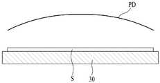
구체적으로, 도 2에 도시된 바와 같이, 40MHz의 RF 전력에 의해 챔버(10)의 반응 공간에 형성되는 플라즈마의 밀도(PD)는 정상파 효과에 의해 RF 전력의 주파수에 따른 파장 길이와 표면 효과(Skin Effect)로 인하여 기판(S)의 가장자리 부분보다 중앙 부분에 집중되게 된다. 이에 따라, 기판(S)의 중심 부분과 가장자리 부분의 두께 차이로 인하여 기판(S)에 형성되는 박막의 균일도가 불균일하다는 문제점이 있다.Specifically, as shown in FIG. 2, the density PD of the plasma formed in the reaction space of the
본 발명은 상술한 문제점을 해결하기 위한 것으로서, 공정 가스의 흐름을 제어하여 대면적 기판에 대한 기판 처리 공정의 균일도를 향상시킬 수 있도록 한 기판 처리 장치 및 이를 이용한 기판 처리 방법을 제공하는 것을 기술적 과제로 한다.SUMMARY OF THE INVENTION The present invention has been made in view of the above-described problems, and provides a substrate processing apparatus and a substrate processing method using the same to control the flow of process gas to improve the uniformity of the substrate processing process for a large area substrate. Shall be.
상술한 기술적 과제를 달성하기 위한 본 발명에 따른 기판 처리 장치는 기판 처리 공정을 위한 공정 공간과 상기 공정 공간에 연통된 배기구를 가지는 챔버; 상기 챔버 내부의 기판 출입 위치에 설치되어 적어도 하나의 기판을 지지하는 기판 지지 프레임; 상기 기판 지지 프레임과 상기 기판을 공정 위치 또는 상기 기판 출입 위치로 승강시키는 서셉터; 상기 서셉터의 상부에 설치되어 상기 기판 상에 공정 가스를 분사하는 가스 분사 수단; 및 상기 가스 분사 수단으로부터 상기 기판 상에 분사되어 상기 배기구로 흐르는 공정 가스의 흐름을 조절하는 가스 흐름 조절 수단을 포함하여 구성되는 것을 특징으로 한다.According to another aspect of the present invention, there is provided a substrate processing apparatus including a chamber having a process space for a substrate processing process and an exhaust port communicating with the process space; A substrate support frame installed at a substrate entrance position in the chamber to support at least one substrate; A susceptor for elevating the substrate support frame and the substrate to a process position or the substrate entrance position; Gas injection means installed on an upper portion of the susceptor to inject a process gas onto the substrate; And gas flow control means for controlling the flow of the process gas injected from the gas injection means onto the substrate and flowing to the exhaust port.
상기 가스 흐름 조절 수단은 상기 기판 상에서 상기 배기구로 흐르는 공정 가스의 흐름을 상기 기판의 가장자리 부분에서 정체시키는 것을 특징으로 한다.The gas flow adjusting means is characterized by stagnation of the flow of the process gas flowing in the exhaust port on the substrate at the edge portion of the substrate.
상기 가스 흐름 조절 수단은 상기 기판 지지 프레임에 지지된 상기 기판의 높이보다 더 높은 높이를 가지도록 상기 기판 지지 프레임으로부터 돌출되어 상기 기판의 측면에 마주보는 돌출부를 포함하여 구성되는 것을 특징으로 한다.The gas flow control means is characterized in that it comprises a protrusion protruding from the substrate support frame to face the side of the substrate to have a height higher than the height of the substrate supported on the substrate support frame.
상기 가스 흐름 조절 수단은 상기 돌출부의 높이를 증가시키기 위한 높이 조절부를 더 포함하여 구성되며, 상기 높이 조절부는 상기 돌출부에 형성된 승강 가이드 홈; 상기 승강 가이드 홈에 승강 가능하게 삽입된 승강 블록; 및 상기 기판 지지 프레임의 배면에 설치되어 상기 승강 블록을 상기 승강 가이드 홈 내에서 승강시켜 상기 돌출부의 높이를 증가시키는 블록 승강 부재를 포함하여 구성되는 것을 특징으로 한다.The gas flow adjusting means further comprises a height adjusting portion for increasing the height of the protrusion, the height adjusting portion is a lifting guide groove formed in the protrusion; An elevating block inserted into the elevating guide groove so as to elevate; And a block elevating member installed on a rear surface of the substrate supporting frame to elevate the elevating block in the elevating guide groove to increase the height of the protrusion.
상기 가스 흐름 조절 수단은 상기 기판 지지 프레임에 지지된 상기 기판의 높이보다 더 높은 높이로 형성되어 상기 기판의 측면에 마주보도록 상기 기판 지지 프레임에 설치된 가스 정체 프레임을 포함하여 구성되는 것을 특징으로 한다.The gas flow adjusting means may be formed to have a height higher than the height of the substrate supported by the substrate support frame, and configured to include a gas stagnation frame installed on the substrate support frame to face the side of the substrate.
상기 가스 흐름 조절 수단은 상기 가스 정체 프레임의 높이를 증가시키기 위한 높이 조절부를 더 포함하여 구성되며, 상기 높이 조절부는 상기 가스 정체 프레임에 형성된 승강 가이드 홈; 상기 승강 가이드 홈에 승강 가능하게 삽입된 승강 블록; 및 상기 기판 지지 프레임의 배면에 설치되어 상기 승강 블록을 상기 승강 가이드 홈 내에서 승강시켜 상기 가스 정체 프레임의 높이를 조절하는 블록 승강 부재를 포함하여 구성되는 것을 특징으로 한다.The gas flow adjusting means further comprises a height adjusting unit for increasing the height of the gas stagnation frame, the height adjusting unit is a lifting guide groove formed in the gas stagnation frame; An elevating block inserted into the elevating guide groove so as to elevate; And a block elevating member disposed on a rear surface of the substrate supporting frame to elevate the elevating block in the elevating guide groove to adjust the height of the gas stagnation frame.
상기 가스 흐름 조절 수단은 상기 기판 지지 프레임에 지지된 상기 기판의 높이보다 더 높은 높이로 형성되어 상기 기판의 모서리 부분에 마주보도록 상기 기판 지지 프레임의 모서리 부분 상면에 설치된 복수의 가스 정체 프레임을 포함하여 구성되는 것을 특징으로 한다.The gas flow adjusting means may include a plurality of gas stagnant frames formed at a height higher than a height of the substrate supported by the substrate support frame and installed on an edge portion of the substrate support frame so as to face an edge portion of the substrate. It is characterized in that the configuration.
상기 가스 흐름 조절 수단은 상기 복수의 가스 정체 프레임 각각의 높이를 증가시키기 위한 높이 조절부를 더 포함하여 구성되며, 상기 높이 조절부는 상기 복수의 가스 정체 프레임 각각에 형성된 복수의 승강 가이드 홈; 상기 복수의 승강 가이드 홈 각각에 승강 가능하게 삽입된 복수의 승강 블록; 및 상기 기판 지지 프레임의 배면에 설치되어 상기 복수의 승강 블록 각각을 상기 복수의 승강 가이드 홈 각각의 내부에서 승강시켜 상기 복수의 가스 정체 프레임 각각의 높이를 조절하는 복수의 블록 승강 부재를 포함하여 구성되는 것을 특징으로 한다.The gas flow adjusting means further includes a height adjusting part for increasing the height of each of the plurality of gas stagnation frames, wherein the height adjusting part comprises a plurality of lifting guide grooves formed in each of the plurality of gas stagnation frames; A plurality of lifting blocks inserted into and liftable from each of the plurality of lifting guide grooves; And a plurality of block elevating members disposed on a rear surface of the substrate supporting frame to elevate each of the plurality of elevating blocks in each of the plurality of elevating guide grooves to adjust heights of the plurality of gas stagnation frames. It is characterized by.
상기 가스 흐름 조절 수단은 상기 기판의 가장자리 부분에 상대적으로 가깝도록 상기 가스 분사 수단의 가장자리 부분에 소정 높이로 설치되어 상기 기판의 가장자리 부분에 상기 공정 가스를 분사하는 가스 분사 블록을 포함하여 구성되는 것을 특징으로 한다.The gas flow control means is configured to include a gas injection block which is installed at a predetermined height on the edge portion of the gas injection means to be relatively close to the edge portion of the substrate to inject the process gas to the edge portion of the substrate It features.
상기 기판 처리 장치는 상기 챔버의 내벽에 설치되어 상기 서셉터의 하강시 상기 기판 지지 프레임을 지지하는 복수의 프레임 지지 부재를 더 포함하여 구성되며, 상기 기판 지지 프레임은 상기 서셉터의 중앙 부분을 제외한 가장자리 부분에 중첩됨과 아울러 적어도 하나의 일측 개구부를 가지도록 형성되어 상기 서셉터의 상승시 상기 서셉터의 가장자리 부분에 안착되는 제 1 기판 지지 플레이트; 상기 서셉터의 상승시 상기 적어도 하나의 일측 개구부에 삽입되어 상기 기판을 지지하도록 상기 서셉터의 일측 가장자리 부분에 설치된 적어도 하나의 제 2 기판 지지 플레이트; 및 상기 복수의 프레임 지지 부재 각각에 대응되도록 상기 제 1 기판 지지 플레이트에 형성된 복수의 지지 홀을 포함하여 구성되는 것을 특징으로 한다.The substrate processing apparatus further includes a plurality of frame support members installed on an inner wall of the chamber to support the substrate support frame when the susceptor is lowered, wherein the substrate support frame excludes a central portion of the susceptor. A first substrate support plate which overlaps the edge portion and has at least one side opening and is seated on the edge portion of the susceptor when the susceptor is raised; At least one second substrate support plate inserted in the at least one side opening to support the substrate when the susceptor is raised; And a plurality of support holes formed in the first substrate support plate so as to correspond to each of the plurality of frame support members.
상기 가스 흐름 조절 수단은 상기 기판 지지 프레임에 지지된 상기 기판의 높이보다 더 높은 높이를 가지도록 상기 제 1 및 제 2 기판 지지 플레이트로부터 돌출되어 상기 기판의 측면에 마주보는 돌출부를 포함하여 구성되는 것을 특징으로 한다.The gas flow control means includes a protrusion protruding from the first and second substrate support plates to face the side of the substrate to have a height higher than the height of the substrate supported by the substrate support frame. It features.
상기 가스 흐름 조절 수단은 상기 기판 지지 프레임에 지지된 상기 기판의 높이보다 더 높은 높이로 형성되어 상기 기판의 측면에 마주보도록 상기 제 1 및 제 2 기판 지지 플레이트 각각에 설치된 제 1 및 제 2 가스 정체 프레임을 포함하여 구성되는 것을 특징으로 한다.The gas flow regulating means is formed at a height higher than the height of the substrate supported by the substrate support frame, the first and second gas stagnation installed on each of the first and second substrate support plates to face the side of the substrate. It is characterized by including a frame.
상기 가스 흐름 조절 수단은 상기 기판 지지 프레임에 지지된 상기 기판의 높이보다 더 높은 높이로 형성되어 상기 기판의 모서리 부분에 마주보도록 상기 제 1 기판 지지 플레이트의 모서리 부분 상면에 설치된 복수의 가스 정체 프레임을 포함하여 구성되는 것을 특징으로 한다.The gas flow adjusting means may include a plurality of gas stagnation frames formed at a height higher than a height of the substrate supported by the substrate support frame and installed on an upper surface of a corner portion of the first substrate support plate to face an edge portion of the substrate. Characterized in that it comprises a.
상기 기판 처리 장치는 상기 서셉터를 관통하도록 배치되어 상기 기판 출입시 상기 기판 지지 프레임에 지지되는 복수의 기판의 일측 가장자리 부분을 제외한 나머지 타측 가장자리 부분을 지지하는 복수의 기판 지지 부재를 더 포함하여 구성되는 것을 특징으로 한다.The substrate processing apparatus further includes a plurality of substrate supporting members disposed to pass through the susceptor to support the other edge portions of the substrate, except for one edge portion of the plurality of substrates supported by the substrate support frame when the substrate enters and exits the substrate. It is characterized by.
상기 가스 흐름 조절 수단은 상기 기판의 가장자리 부분에 상대적으로 가깝도록 상기 가스 분사 수단의 가장자리 부분에 소정 높이로 설치되어 상기 기판의 가장자리 부분에 상기 공정 가스를 분사하여 상기 기판의 가장자리 부분에서의 상기 공정 가스 흐름을 정체시키는 가스 분사 블록을 포함하여 구성되는 것을 특징으로 한다.The gas flow control means is installed at a predetermined height at the edge portion of the gas injection means so as to be relatively close to the edge portion of the substrate to inject the process gas to the edge portion of the substrate to the process at the edge portion of the substrate And a gas injection block to stagnate the gas flow.
상기 가스 흐름 조절 수단은 상기 가스 분사 수단의 가장자리 부분에 설치된 블록 지지부; 및 상기 서셉터의 가장자리 부분에 상대적으로 가깝도록 상기 블록 지지부의 하부에 소정 높이를 가지도록 설치되어 상기 기판의 가장자리 부분에서의 상기 공정 가스 흐름을 정체시키는 가스 정체 블록을 포함하여 구성되는 것을 특징으로 한다.The gas flow adjusting means may include a block support provided at an edge of the gas injection means; And a gas stagnation block installed at a lower portion of the block support portion so as to be relatively close to an edge portion of the susceptor to stagnate the process gas flow at an edge portion of the substrate. do.
상술한 기술적 과제를 달성하기 위한 본 발명에 따른 기판 처리 방법은 상기 기판 처리 장치를 이용하여 기판에 대한 기판 처리 공정을 수행하는 것을 특징으로 하는 기판 처리 방법.The substrate processing method according to the present invention for achieving the above technical problem is to perform a substrate processing process for a substrate using the substrate processing apparatus.
상술한 기술적 과제를 달성하기 위한 본 발명에 따른 기판 처리 방법은 챔버 내부에 배치되는 기판 지지 프레임에 설치된 가스 흐름 조절 수단의 높이를 조절하는 단계; 상기 기판 지지 프레임을 상기 챔버 내부의 기판 출입 위치에 위치시키는 단계; 상기 기판 지지 프레임을 이용하여 상기 기판 출입 위치로 로딩되는 적어도 하나의 기판을 지지하는 단계; 상기 챔버 내부의 반응 공간에 설치된 서셉터를 상승시켜 상기 기판 지지 프레임과 상기 기판을 공정 위치에 위치시키는 단계; 및 상기 기판 상에 공정 가스를 분사하여 상기 공정 가스에 기초하여 이루어지는 기판 처리 공정을 수행하는 단계를 포함하여 이루어지며, 상기 기판 상에 분사되는 공정 가스의 흐름은 상기 가스 흐름 조절 수단에 의해 조절되는 것을 특징으로 한다.Substrate processing method according to the present invention for achieving the above-described technical problem is a step of adjusting the height of the gas flow control means installed in the substrate support frame disposed inside the chamber; Positioning the substrate support frame at a substrate entry position within the chamber; Supporting at least one substrate loaded into the substrate entrance position using the substrate support frame; Raising the susceptor installed in the reaction space inside the chamber to position the substrate support frame and the substrate at a process position; And performing a substrate treatment process based on the process gas by injecting a process gas onto the substrate, wherein the flow of the process gas injected onto the substrate is controlled by the gas flow adjusting means. It is characterized by.
상기 가스 흐름 조절 수단은 상기 기판 지지 프레임에 설치된 적어도 하나의 가스 정체 프레임과 상기 가스 정체 프레임에 승강 가능하게 설치된 승강 블록을 포함하여 구성되며, 상기 가스 흐름 조절 수단의 높이는 상기 승강 블록의 승강 높이에 따라 조절되는 것을 특징으로 한다.The gas flow regulating means includes at least one gas stagnation frame installed on the substrate support frame and a lifting block mounted on the gas stagnation frame so as to be liftable, and the height of the gas flow adjusting means is increased by the lifting height of the lifting block. It is characterized by being adjusted accordingly.
상기 적어도 하나의 기판을 지지하는 단계는 상기 서셉터를 관통하도록 배치된 복수의 기판 지지 부재를 이용하여 상기 기판 지지 프레임에 지지되는 복수의 기판의 일측 가장자리 부분을 제외한 나머지 타측 가장자리 부분을 지지하는 단계를 포함하여 이루어지는 것을 특징으로 한다.The supporting of the at least one substrate may include supporting the other edge portion except for one edge portion of the plurality of substrates supported by the substrate support frame using a plurality of substrate support members disposed to penetrate the susceptor. Characterized in that comprises a.
상술한 바와 같이 본 발명에 따른 기판 처리 장치 및 이를 이용한 기판 처리 방법은 가스 분사 수단 및/또는 기판 지지 프레임에 가스 흐름 조절 수단을 형성하여 기판의 가장자리 부분에서의 공정 가스 흐름을 조절함으로써 기판의 가장자리 부분의 박막 증착(또는 식각)율을 증가시키고, 이를 통해 기판 전체 영역에 대한 기판 처리 공정의 균일도를 향상시킬 수 있다는 효과가 있다.As described above, the substrate processing apparatus and the substrate processing method using the same according to the present invention form a gas flow control means in the gas injection means and / or the substrate support frame to control the process gas flow in the edge portion of the substrate, thereby Increasing the thin film deposition (or etching) rate of the portion, thereby improving the uniformity of the substrate processing process for the entire area of the substrate.
또한, 본 발명에 따른 기판 처리 장치 및 이를 이용한 기판 처리 방법은 기판 상에 소정 두께를 박막을 증착하는데 있어서, 공정 가스의 흐름을 제어하여 대면적 기판에 대한 기판 처리 공정의 균일도를 향상시킬 수 있다는 효과가 있다.In addition, the substrate processing apparatus and the substrate processing method using the same according to the present invention can improve the uniformity of the substrate processing process for a large-area substrate by controlling the flow of process gas in depositing a thin film having a predetermined thickness on the substrate. It works.
도 1은 일반적인 기판 처리 장치를 설명하기 위한 도면이다.
도 2는 일반적인 기판 처리 공정의 플라즈마 밀도를 나타내는 도면이다.
도 3은 본 발명의 제 1 실시 예에 따른 기판 처리 장치를 설명하기 위한 도면이다.
도 4는 도 3에 도시된 서셉터와 기판 지지 프레임 및 가스 흐름 조절 수단을 설명하기 위한 도면이다.
도 5는 도 3에 도시된 "A" 부분을 확대하여 나타내는 확대도이다.
도 6은 도 4에 도시된 I-I 선의 단면을 통해 공정 가스를 흐름을 설명하기 위한 도면이다.
도 7 및 도 8은 도 4에 도시된 가스 흐름 조절 수단의 높이 조절부를 설명하기 위한 도면이다.
도 9는 본 발명의 제 2 실시 예에 따른 기판 처리 장치를 설명하기 위한 도면이다.
도 10은 도 9에 도시된 서셉터와 기판 지지 프레임, 및 가스 흐름 조절 수단의 일 실시 예를 설명하기 위한 도면이다.
도 11은 도 10에 도시된 II-II 선의 단면을 통해 공정 가스를 흐름을 설명하기 위한 도면이다.
도 12는 도 10에 도시된 가스 흐름 조절 수단의 높이 조절부를 설명하기 위한 도면이다.
도 13은 도 9에 도시된 서셉터와 기판 지지 프레임, 및 가스 흐름 조절 수단의 다른 실시 예를 설명하기 위한 도면이다.
도 14는 본 발명의 제 3 실시 예에 따른 기판 처리 장치를 설명하기 위한 도면이다.
도 15는 도 14에 도시된 서셉터와 기판 지지 프레임, 가스 흐름 조절 수단 및 기판 지지 부재를 설명하기 위한 도면이다.
도 16은 도 14에 도시된 서셉터의 하강에 따른 기판 지지 프레임과 기판 지지 부재의 위치를 설명하기 위한 도면이다.
도 17은 본 발명의 제 4 실시 예에 따른 기판 처리 장치를 설명하기 위한 도면이다.
도 18은 도 17에 도시된 "B" 부분을 확대하여 나타내는 확대도이다.
도 19는 본 발명의 제 5 실시 예에 따른 기판 처리 장치를 설명하기 위한 도면이다.
도 20은 본 발명의 제 6 실시 예에 따른 기판 처리 장치를 설명하기 위한 도면이다.
도 21은 도 20에 도시된 "C" 부분을 확대하여 나타내는 확대도이다.
도 22는 본 발명의 제 7 실시 예에 따른 기판 처리 장치를 설명하기 위한 도면이다.1 is a view for explaining a general substrate processing apparatus.
2 is a diagram showing a plasma density of a general substrate processing step.
3 is a view for explaining a substrate processing apparatus according to a first embodiment of the present invention.
4 is a view for explaining the susceptor and the substrate support frame and gas flow adjusting means shown in FIG.
FIG. 5 is an enlarged view illustrating an enlarged portion “A” shown in FIG. 3.
6 is a view for explaining the flow of the process gas through the cross section of the line II shown in FIG.
7 and 8 are views for explaining the height adjustment unit of the gas flow control means shown in FIG.
9 is a diagram for describing a substrate processing apparatus according to a second embodiment of the present invention.
FIG. 10 is a view for explaining an embodiment of the susceptor, the substrate support frame, and the gas flow adjusting means shown in FIG. 9.
FIG. 11 is a view for explaining a process gas flow through a cross section of the II-II line shown in FIG. 10.
12 is a view for explaining the height adjusting unit of the gas flow control means shown in FIG.
FIG. 13 is a view for explaining another embodiment of the susceptor, the substrate support frame, and the gas flow adjusting means shown in FIG. 9.
14 is a diagram for describing a substrate processing apparatus according to a third embodiment of the present invention.
FIG. 15 is a view for explaining the susceptor, the substrate support frame, the gas flow adjusting means, and the substrate support member shown in FIG. 14.
FIG. 16 is a diagram for describing positions of the substrate support frame and the substrate support member according to the lowering of the susceptor illustrated in FIG. 14.
17 is a diagram for describing a substrate processing apparatus according to a fourth embodiment of the present invention.
18 is an enlarged view illustrating an enlarged portion “B” illustrated in FIG. 17.
19 is a diagram for describing a substrate processing apparatus according to a fifth embodiment of the present invention.
20 is a diagram for describing a substrate processing apparatus according to a sixth embodiment.
FIG. 21 is an enlarged view illustrating an enlarged portion “C” illustrated in FIG. 20.
FIG. 22 is a diagram for describing a substrate processing apparatus according to a seventh embodiment.
이하, 도면을 참조로 본 발명에 따른 바람직한 실시 예에 대해서 상세히 설명하기로 한다.Hereinafter, exemplary embodiments of the present invention will be described in detail with reference to the accompanying drawings.
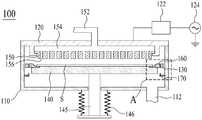
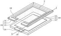
도 3은 본 발명의 제 1 실시 예에 따른 기판 처리 장치를 설명하기 위한 도면이고, 도 4는 도 3에 도시된 서셉터와 기판 지지 프레임 및 가스 흐름 조절 수단을 설명하기 위한 도면이다.3 is a view for explaining a substrate processing apparatus according to a first embodiment of the present invention, Figure 4 is a view for explaining the susceptor, the substrate support frame and the gas flow control means shown in FIG.
도 3 및 도 4를 참조하면, 본 발명의 제 1 실시 예에 따른 기판 처리 장치(100)는 챔버(110), RF 전력이 공급되는 고주파 전극부(120), 기판(S)을 지지하는 기판 지지 프레임(130), 기판 지지 프레임(130)과 기판(S)을 공정 위치 또는 기판 출입 위치로 승강시키는 서셉터(140), 기판(S) 상에 공정 가스를 분사하는 가스 분사 수단(150), 및 기판 지지 프레임(130)에 형성되어 가스 분사 수단(150)으로부터 기판(S) 상에 분사되는 공정 가스의 흐름을 조절하는 가스 흐름 조절 수단(160)을 포함하여 구성된다.3 and 4, the
챔버(110)는 기판 처리 공정을 위한 반응 공간을 제공한다. 상기의 챔버(110)의 일측 바닥면은 반응 공간을 배기시키기 위한 배기관(112)에 연통된다.
고주파 전극부(120)는 반응 공간을 밀폐하도록 챔버(110)의 상부에 설치된다.The high
고주파 전극부(120)는 정합 부재(122)를 통해 RF(Radio Frequence) 전원(124)에 전기적으로 접속된다. 정합 부재(122)는 고주파 전극부(120)와 RF 전원(124) 간에 접속되어 RF 전원(124)으로부터 고주파 전극부(120)에 공급되는 RF 전력의 부하 임피던스와 소스 임피던스를 정합시킨다. RF 전원(124)은 27MHz ~ 100MHz의 RF 전력을 생성하여 고주파 전극부(120)에 공급한다.The high
기판 지지 프레임(130)은 챔버(110)에 마련된 반응 공간의 기판 출입 위치에 설치되어 외부의 기판 로딩 장치로부터 챔버(110)의 내부로 로딩되는 기판(S)을 지지한다. 상기의 기판 지지 프레임(130)은 전도성 재질로 이루어질 수 있다. 기판 지지 프레임(130)은 챔버(110)의 내벽에 설치된 복수의 프레임 지지 부재(170)에 의해 지지된다. 복수의 프레임 지지 부재(170)는 서셉터(140)의 하강시 기판 지지 프레임(130)을 지지함으로써 기판 지지 프레임(130)이 기판 출입 위치에 위치하도록 한다.The
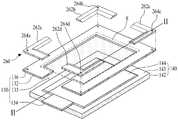
상기의 기판 지지 프레임(130)은, 도 4에 도시된 바와 같이, 제 1 및 제 2 기판 지지 플레이트(132, 134), 및 복수의 지지 홀(136)을 포함하여 구성된다.As illustrated in FIG. 4, the
제 1 기판 지지 플레이트(132)는 서셉터(140)의 중앙 부분을 제외한 가장자리 부분에 중첩되도록 배치되며, 서셉터(140)의 중앙 부분에 대응되는 중앙 개구부와 기판 로딩 장치가 출입하는 측면 개구부(133)를 포함하도록 "⊃"자 형태로 형성되어 기판(S)의 배면 가장자리 부분을 지지한다. 이러한 제 1 기판 지지 플레이트(132)는 서셉터(140)의 상승시 서셉터(140)의 가장자리 부분에 안착된다.The first
제 2 기판 지지 플레이트(134)는 제 1 기판 지지 플레이트(132)의 측면 개구부(133)에 대응되도록 서셉터(140)의 일측 가장자리 부분에 장착된다. 이러한 제 2 기판 지지 플레이트(134)는 서셉터(140)의 상승시 제 1 기판 지지 플레이트(132)의 측면 개구부(133)에 삽입되어 기판(S)의 배면 일측 가장자리 부분을 지지한다. 이때, 서셉터(140)의 상승에 따라 제 2 기판 지지 플레이트(134)가 제 1 기판 지지 플레이트(132)의 측면 개구부(133)에 삽입될 경우, 제 1 및 제 2 기판 지지 플레이트(132, 134)는 사각틀 형태를 가지게 된다.The second
복수의 지지 홀(136) 각각은 복수의 프레임 지지 부재(170) 각각에 대응되도록 제 1 기판 지지 플레이트(132)의 각 모서리 부분에 형성된다. 상기 복수의 지지 홀(136) 각각에는 서셉터(140)의 하강에 따른 기판 지지 프레임(130)의 하강시 복수의 프레임 지지 부재(170) 각각이 삽입된다. 이에 따라, 기판 지지 프레임(130)은 서셉터(140)의 하강시 복수의 프레임 지지 부재(170)에 의해 지지됨으로써 챔버(110) 내부의 기판 출입 위치에 위치하게 된다.Each of the plurality of support holes 136 is formed at each corner portion of the first
이와 같은, 기판 지지 프레임(130)은 서셉터(140)의 승강에 따라 승강된다. 즉, 챔버(110) 내부로 기판(S)이 로딩될 경우, 제 1 기판 지지 플레이트(132)는 서셉터(140)의 하강에 따라 하강되면서 기판 출입 위치에서 복수의 프레임 지지 핀(170)에 의해 지지되고, 제 2 기판 지지 플레이트(134)는 홈 위치로 하강되는 서셉터(140)의 하강에 의해 기판 출입 위치보다 낮은 위치에 위치하게 된다.As such, the
반면에, 기판 처리 공정을 위해 서셉터(140)가 공정 위치로 상승하게 되면, 기판 지지 프레임(130)은 서셉터(140)의 상승에 따라 기판 출입 위치에서부터 기판(S)을 지지한 상태로 기판 처리 공정 위치로 상승하게 된다. 이에 따라, 기판 처리 공정시 기판(S)의 가장자리 부분은 기판 지지 프레임(130)에 의해 지지되고, 기판(S)의 가장자리 부분을 제외한 기판(S)의 나머지 부분은 서셉터(140)에 의해 지지된다. 이때, 기판 지지 프레임(130) 상에 지지되는 기판(S)의 가장자리 부분의 폭 또는 기판 지지 프레임(130)과 기판(S)의 접촉 부분의 폭은 기판(S)의 끝단으로부터 기판(S)의 절반 길이의 30% 이내로 설정되는 것이 바람직하다. 예를 들어, 기판(S)의 길이가 1300mm일 경우, 기판 지지 프레임(130) 상에 지지되는 기판(S)의 가장자리 부분의 폭은 195mm 정도가 될 수 있다.On the other hand, when the
서셉터(140)는 고주파 전극부(120)에 대향되는 대향 전극으로써, 서셉터(140)를 승강시키는 승강축(145)을 통해 전기적으로 접지된다. 승강축(145)은 승강 장치(미도시)에 의해 상하 방향으로 승강된다. 챔버(110)의 하면 외부로 노출되는 상기의 승강축(145)은 챔버(110)의 하면에 설치되는 벨로우즈(146)에 감싸여진다. 이러한 서셉터(140)는 기판 지지 프레임(130)의 하부에 승강 가능하도록 설치되어 승강 장치의 구동에 따른 승강축(145)의 승강에 의해 기판 지지 프레임(130)과 기판(S)을 공정 위치 또는 기판 출입 위치로 승강시킨다.The
구체적으로, 서셉터(140)는, 기판 출입 공정시, 기판 지지 프레임(130)의 하부에 위치하도록 하강된 상태를 유지한다. 상기의 기판 출입 공정이 완료될 경우, 서셉터(140)는 기판 처리 공정을 위해 상승함으로써 기판 출입 위치에 위치한 기판 지지 프레임(130)과 기판(S)을 지지하면서 기판 지지 프레임(130)과 기판(S)을 공정 위치로 상승시킨다. 또한 기판 처리 공정이 완료될 경우 서셉터(140)는 기판 지지 프레임(130)과 기판(S)이 기판 출입 위치에 위치하도록 홈 위치로 하강함으로써 공정 위치에 위치한 기판 지지 프레임(130)이 복수의 프레임 지지 부재(170)에 지지되도록 한다.Specifically, the
상기의 서셉터(140)는 베이스 부재(142) 및 기판 안착부(144)를 포함하여 구성된다.The
베이스 부재(142)는 사각 형태를 가지도록 형성되어 챔버(110)의 바닥면을 관통하는 승강축(145)에 의해 승강 가능하도록 지지된다. 상기 베이스 부재(142)의 일측 가장자리에는 상술한 기판 지지 프레임(130)의 제 2 기판 지지 플레이트(134)가 장착된다.The
기판 안착부(144)는 기판 지지 프레임(130)의 중앙 개구부에 대응되도록 베이스 부재(142)의 가장자리 부분(143)을 제외한 안쪽 나머지 부분으로부터 소정 높이로 돌출된다. 이때, 기판 안착부(144)의 높이는 기판 지지 프레임(130)의 높이와 동일한 높이를 갖는다. 상기의 기판 안착부(144)에는 베이스 부재(142)의 상승시 기판 지지 프레임(130)에 지지된 기판(S)이 안착된다. 상기 베이스 부재(142)의 가장자리 부분(143)에는 베이스 부재(142)의 상승시 기판 지지 프레임(130)의 제 1 기판 지지 플레이트(132)가 안착된다.The
가스 분사 수단(150)은 서셉터(140)에 대향되도록 고주파 전극부(120)의 하부에 설치되어 기판 상에 공정 가스를 분사한다. 이때, 가스 분사 수단(150)과 고주파 전극부(120) 사이에는 고주파 전극부(120)를 관통하는 가스 공급관(152)으로부터 공급되는 공정 가스가 확산되는 가스 확산 공간(154)이 형성된다. 상기의 가스 분사 수단(150)은 가스 확산 공간(154)의 공정 가스를 반응 공간의 전 부분에 균일하게 분사하기 위한 복수의 가스 샤워 홀(156)을 포함하여 구성된다. 상기의 가스 분사 수단(150)에 의해 기판(S) 상에 분사된 공정 가스는 가스 흐름 조절 수단(160)에 의해 기판(S)의 가장자리 부분에서 정체되면서 기판(S)의 측면과 챔버(110) 사이를 통해 배기구(112)로 배기된다.The gas injection means 150 is installed under the high
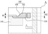
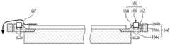
가스 흐름 조절 수단(160)은 기판 지지 프레임(130)에 설치되어 가스 분사 수단(150)으로부터 기판(S) 상에 분사된 기판(S) 상의 가스 흐름을 조절한다. 이를 위해, 가스 흐름 조절 수단(160)은, 도 4 및 도 5에 도시된 바와 같이, 돌출부(162), 및 단턱부(164)를 포함하여 구성된다.The gas flow adjusting means 160 is installed in the
돌출부(162)는 기판 지지 프레임(130)에 지지된 기판(S)의 제 1 높이(H1)보다 더 높은 제 2 높이(H2)를 가지도록 기판 지지 프레임(1300)의 외측 가장자리 부분으로부터 돌출된다. 즉, 돌출부(162)는 기판 지지 프레임(130)의 제 1 및 제 2 기판 지지 플레이트(132, 134) 각각의 외측 가장자리 부분으로부터 제 2 높이(H2)를 가지도록 돌출된다.The
단턱부(164)는 기판(S)의 측면에 마주보는 돌출부(162)의 일측면에 형성된다. 이때, 단턱부(164)는 소정의 기울기를 가지도록 형성될 수 있다.The stepped
이와 같은, 가스 흐름 조절 수단(160)은, 도 6에 도시된 바와 같이, 단턱부(164)와 돌출부(162)를 통해 기판(S)의 가장자리 부분 상부에서의 공정 가스 흐름(GF)을 정체시킴으로써 공정 가스가 기판(S)의 가장자리 부분 상에서 머무는 시간을 증가시킨다. 이에 따라, 가스 흐름 조절 수단(160)은 기판(S)의 가장자리 부분에 대한 가스(또는 플라즈마) 반응 시간을 증가시킴으로써 기판(S)의 가장자리 부분의 박막 증착(또는 식각)율을 상대적으로 증가시켜 기판(S) 전체 영역에 대한 기판 처리 공정의 균일도를 향상시킨다.As shown in FIG. 6, the gas flow regulating means 160 stagnates the process gas flow GF above the edge portion of the substrate S through the
한편, 상술한 가스 흐름 조절 수단(160)는, 도 7에 도시된 바와 같이, 돌출부(162)의 높이를 증가시키기 위한 높이 조절부(166)를 더 포함하여 구성된다.On the other hand, the gas flow control means 160 described above, as shown in Figure 7, is configured to further include a
높이 조절부(166)는 승강 가이드 홈(166a), 승강 블록(166b), 및 블록 승강 부재(166c)를 포함하여 구성된다.The
승강 가이드 홈(166a)은 승강 블록(166b)의 형태에 대응되도록 돌출부(162)의 상면으로부터 소정 깊이를 가지도록 오목하게 형성되어 승강 블록(166b)의 승강을 가이드한다.The lifting
승강 블록(166b)은 승강 가이드 홈(166a) 내부에 승강 가능하게 삽입된다.The elevating
블록 승강 부재(166c)는 승강 가이드 홈(166a)에 대응되는 기판 지지 프레임(130)의 배면에 설치된다. 상기의 블록 승강 부재(166c)는 기판 지지 프레임(130)을 관통하여 승강 블록(166b)에 접촉되는 체결 볼트가 될 수 있다. 이러한 블록 승강 부재(166c)는 승강 블록(166b)을 승강 가이드 홈(166a) 내부에서 승강시켜 승강 블록(166b)을 돌출부(162)의 상부로 돌출시킴으로써 돌출부(162)의 높이를 증가시킨다.The
이와 같은, 높이 조절부(166)는 기판 처리 공정의 공정 조건(예를 들어, 기판 크기, 공정 온도, 공정 가스 량 등)에 따라, 도 8에 도시된 바와 같이, 블록 승강 부재(166c)를 회전시켜 승강 블록(166b)의 높이 조절을 통해 돌출부(162)의 높이를 증가시킴으로써 공정 가스가 기판(S)의 가장자리 부분 상에서 머무는 시간을 더욱 증가시키게 된다.As such, the
도 3 및 도 4를 참조하여 상술한 바와 같은 본 발명의 제 1 실시 예에 따른 기판 처리 장치(100)를 이용한 기판 처리 방법을 설명하면 다음과 같다.A substrate processing method using the
먼저, 기판 출입 위치에 위치된 기판 지지 프레임(130)을 이용하여 기판 출입 위치로 로딩되는 기판(S)을 지지한다.First, the substrate S loaded to the substrate entrance position is supported using the
그런 다음, 챔버(110) 내부의 반응 공간에 설치된 서셉터(140)를 상승시켜 기판 지지 프레임(130)과 기판(S)을 공정 위치에 위치시킨다.Then, the
그런 다음, 챔버(110) 내부에 진공 분위기를 형성한 후, 기판(S) 상에 공정 가스를 분사함과 아울러 챔버(110)의 상부에 설치된 고주파 전극부(120)에 RF 전력을 공급함으로써 반응 공간에 플라즈마를 발생시켜 기판(S)에 대한 기판 처리 공정을 수행한다. 상기의 기판 처리 공정에서 기판(S) 상에 분사되는 공정 가스의 흐름은 기판 지지 프레임(130)에 설치된 가스 흐름 조절 수단(160)에 의해 조절된다. 이때, 가스 흐름 조절 수단(160)은, 도 6에 도시된 바와 같이, 단턱부(164)와 돌출부(162)를 통해 기판(S)의 가장자리 부분 상부에서의 가스 흐름을 정체시킴으로써 공정 가스가 기판(S)의 가장자리 부분 상에서 머무는 시간을 증가시킨다. 이에 따라, 상기의 기판 처리 공정에서는 가스 흐름 조절 수단(160)에 의해 기판(S)의 가장자리 부분에 대한 가스(또는 플라즈마) 반응 시간이 증가됨으로써 기판(S)의 가장자리 부분의 박막 증착(또는 식각)율이 상대적으로 증가하게 된다.Then, after forming a vacuum atmosphere inside the
한편, 상술한 기판 처리 방법에서, 가스 흐름 조절 수단(160)가 높이 조절부(166)를 포함하여 구성되는 경우, 도 8에 도시된 바와 같이, 높이 조절부(166)를 이용해 가스 흐름 조절 수단(160)의 돌출부(162) 높이를 조절한 다음, 돌출부(162)의 높이가 조절된 가스 흐름 조절 수단(160)가 형성된 기판 지지 프레임(130)을 챔버(110) 내부의 기판 출입 위치에 위치시키는 공정을 더 포함하여 이루어질 수 있다.Meanwhile, in the above-described substrate processing method, when the gas flow adjusting means 160 includes the
따라서, 본 발명의 제 1 실시 예에 따른 기판 처리 장치(100)를 이용한 기판 처리 방법은 가스 흐름 조절 수단(160)에 의한 공정 가스의 흐름 조절을 통해 기판(S)의 가장자리 부분의 박막 증착(또는 식각)율을 증가시킴으로써 기판(S) 전체 영역에 대한 기판 처리 공정의 균일도를 향상시킬 수 있다.Therefore, in the substrate processing method using the
또한, 기판 상에 소정 두께를 박막을 증착하는데 있어서, 본 발명의 제 1 실시 예에 따른 기판 처리 장치(100)를 이용한 기판 처리 방법은 공정 가스의 흐름을 제어하여 대면적 기판에 대한 기판 처리 공정의 균일도를 향상시킬 수 있다.In addition, in depositing a thin film having a predetermined thickness on a substrate, a substrate processing method using the
도 9는 본 발명의 제 2 실시 예에 따른 기판 처리 장치를 설명하기 위한 도면이고, 도 10은 도 9에 도시된 서셉터와 기판 지지 프레임 및 가스 흐름 조절 수단을 설명하기 위한 도면이다.9 is a view for explaining a substrate processing apparatus according to a second embodiment of the present invention, Figure 10 is a view for explaining the susceptor, the substrate support frame and the gas flow control means shown in FIG.
도 9 및 도 10을 참조하면, 본 발명의 제 2 실시 예에 따른 기판 처리 장치(200)는 챔버(110), RF 전력이 공급되는 고주파 전극부(120), 기판(S)을 지지하는 기판 지지 프레임(130), 챔버(110)의 내벽에 설치되어 기판 지지 프레임(130)을 지지하는 복수의 프레임 지지 부재(170), 기판 지지 프레임(130)과 기판(S)을 공정 위치 또는 기판 출입 위치로 승강시키는 서셉터(140), 기판(S) 상에 공정 가스를 분사하는 가스 분사 수단(150), 및 기판 지지 프레임(130)에 형성되어 가스 분사 수단(150)으로부터 기판(S) 상에 분사되는 공정 가스의 흐름을 조절하는 가스 흐름 조절 수단(260)을 포함하여 구성된다.9 and 10, the
상기의 구성을 가지는 본 발명의 제 2 실시 예에 따른 기판 처리 장치(200)에서 가스 흐름 조절 수단(260)을 제외한 나머지 구성들은 상술한 본 발명의 제 1 실시 예에 따른 기판 처리 장치(100)와 동일하므로 동일한 구성들에 대한 설명은 상술한 설명으로 대신하기로 하고, 이하 동일한 도면 부호를 부여하기로 한다.In the
가스 흐름 조절 수단(260)은 기판 지지 프레임(130)에 지지된 기판(S)의 모서리 부분에 마주보도록 기판 지지 프레임(130)의 모서리 부분 상면에 설치되어 가스 분사 수단(150)으로부터 기판(S) 상에 분사된 기판(S) 상의 가스 흐름을 조절한다. 이를 위해, 가스 흐름 조절 수단(260)은 기판 지지 프레임(130)의 제 1 기판 지지 플레이트(132)의 각 모서리 부분에 설치된 제 1 내지 제 4 가스 정체 프레임(262a 내지 262d)을 포함하여 구성된다.The gas flow adjusting means 260 is installed on the upper surface of the corner portion of the
제 1 내지 제 4 가스 정체 프레임(262a 내지 262d) 각각은 기판 지지 프레임(130)에 지지된 기판(S)의 제 1 높이보다 더 높은 제 2 높이를 가지도록 "L"자 형태로 형성되어 제 1 기판 지지 플레이트(132)의 각 모서리 부분에 설치된다. 이때, 기판(S)의 각 모서리 부분에 마주보는 제 1 내지 제 4 가스 정체 프레임(262a 내지 262d) 각각의 내측면은 소정의 기울기를 가지도록 형성될 수 있다.Each of the first to fourth gas
제 1 내지 제 4 가스 정체 프레임(262a 내지 262d) 각각의 각 모서리 부분에는 제 1 기판 지지 플레이트(132)에 형성된 복수의 지지 홀(136) 각각에 대응되는 더미 지지 홀(264a 내지 264d)이 형성될 수 있다. 더미 지지 홀(264a 내지 264d) 각각에는 제 1 기판 지지 플레이트(132)의 지지 홀(136)에 삽입되어 관통하는 프레임 지지 부재(170)가 삽입된다. 한편, 프레임 지지 부재(170)가 짧아 지지 홀(136)을 관통하지 않을 경우에는 상기의 더미 지지 홀(264a 내지 264d)은 생략될 수 있다.
이와 같은, 가스 흐름 조절 수단(260)은, 도 11에 도시된 바와 같이, 제 1 내지 제 4 가스 정체 프레임(262a 내지 262d)을 통해 기판(S)의 가장자리 부분 상부에서의 공정 가스 흐름(GF)을 정체시킴으로써 공정 가스가 기판(S)의 가장자리 부분 상에서 머무는 시간을 증가시킨다. 이에 따라, 가스 흐름 조절 수단(260)은 기판(S)의 가장자리 부분에 대한 가스(또는 플라즈마) 반응 시간을 증가시킴으로써 기판(S)의 가장자리 부분의 박막 증착(또는 식각)율을 상대적으로 증가시켜 기판(S) 전체 영역에 대한 기판 처리 공정의 균일도를 향상시킨다.As such, the gas flow adjusting means 260, as shown in Figure 11, the process gas flow (GF) above the edge portion of the substrate (S) through the first to fourth gas stagnation frame (262a to 262d) Stagnation) increases the time for which the process gas stays on the edge portion of the substrate (S). Accordingly, the gas flow control means 260 increases the gas (or plasma) reaction time for the edge portion of the substrate S to relatively increase the thin film deposition (or etching) rate of the edge portion of the substrate S. The uniformity of the substrate processing process with respect to the entire area of the substrate S is improved.
상술한 가스 흐름 조절 수단(260)은 기판(S)의 모서리 부분에 대한 박막 증착(또는 식각)율을 상대적으로 증가시키는 것이기 때문에, 낮은 공정 압력(예를 들어, 수 Torr)에서 기판 처리 공정을 수행하는 기판 처리 장치에 적합하다.Since the above-described gas flow control means 260 relatively increases the thin film deposition (or etching) rate with respect to the edge portion of the substrate S, the gas flow adjusting means 260 may perform the substrate processing process at a low process pressure (for example, several Torr). It is suitable for the substrate processing apparatus to perform.
한편, 상술한 가스 흐름 조절 수단(260)은, 도 12에 도시된 바와 같이, 제 1 내지 제 4 가스 정체 프레임(262a 내지 262d) 각각의 높이를 증가시키기 위한 높이 조절부(266)를 더 포함하여 구성된다.Meanwhile, the gas flow adjusting means 260 described above further includes a
높이 조절부(266)는 복수의 승강 가이드 홈(266a), 복수의 승강 블록(266b), 및 복수의 블록 승강 부재(266c)를 포함하여 구성된다.The
복수의 승강 가이드 홈(266a) 각각은 복수의 승강 블록(266b) 각각의 형태에 대응되도록 각 가스 정체 프레임(262a 내지 262d)의 상면으로부터 소정 깊이를 가지도록 오목하게 형성되어 복수의 승강 블록(266b) 각각의 승강을 가이드한다.Each of the plurality of lifting
복수의 승강 블록(266b) 각각은 각 승강 가이드 홈(266a) 내부에 승강 가능하게 삽입된다.Each of the plurality of lifting
복수의 블록 승강 부재(266c) 각각은 복수의 승강 가이드 홈(266a) 각각에 대응되는 기판 지지 프레임(130)의 배면에 설치된다. 상기 복수의 블록 승강 부재(266c) 각각은 기판 지지 프레임(130)을 관통하여 복수의 승강 블록(266b) 각각에 접촉되는 체결 볼트가 될 수 있다. 이러한 복수의 블록 승강 부재(266c) 각각은 복수의 승강 블록(266b) 각각을 각 승강 가이드 홈(266a)의 내부에서 승강시켜 복수의 승강 블록(266b) 각각을 각 가스 정체 프레임(262a 내지 262d)의 상부로 돌출시킴으로써 각 가스 정체 프레임(262a 내지 262d)의 높이를 증가시킨다.Each of the plurality of
이와 같은, 높이 조절부(266)는 기판 처리 공정의 공정 조건(예를 들어, 기판 크기, 공정 온도, 공정 가스 량 등)에 따라 복수의 블록 승강 부재(266c) 각각을 회전시켜 각 승강 블록(266b)의 높이 조절을 통해 각 가스 정체 프레임(262a 내지 262d)의 높이를 증가시킴으로써 공정 가스(GF)가 기판(S)의 가장자리 부분 상에서 머무는 시간을 더욱 증가시키게 된다.As such, the
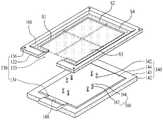
한편, 상대적으로 높은 공정 압력에서 기판 처리 공정을 수행하는 기판 처리 장치에서는 기판(S)의 가장자리 부분에 대한 박막 증착(또는 식각)율을 상대적으로 증가시켜야 기판(S) 전체 영역에 대한 기판 처리 공정의 균일도를 향상시킬 수 있다. 이를 위해, 변형 실시 예에 따른 가스 흐름 조절 수단(1260)은, 도 13에 도시된 바와 같이, 기판 지지 프레임(130)의 제 1 및 제 2 기판 지지 플레이트(132, 134) 각각에 설치된 제 1 및 제 2 가스 정체 프레임(1262, 1264)을 포함하여 구성된다.Meanwhile, in a substrate processing apparatus that performs a substrate processing process at a relatively high process pressure, the thin film deposition (or etching) rate of the edge portion of the substrate S must be relatively increased to process the substrate processing process for the entire area of the substrate S. FIG. Can improve the uniformity. To this end, the gas flow control means 1260 according to the modified embodiment, the first is installed on each of the first and second
제 1 가스 정체 프레임(1262)은 제 1 기판 지지 플레이트(132)의 측면 개구부(133)에 중첩되는 제 2 프레임 삽입부(1263)를 가짐과 아울러 기판 지지 프레임(130)에 지지된 기판(S)의 제 1 높이보다 더 높은 제 2 높이를 가지도록 "⊃"자 형태로 형성되어 제 1 기판 지지 플레이트(132)의 외측 가장자리 부분에 설치된다. 이에 따라, 제 1 가스 정체 프레임(1262)은 제 1 기판 지지 플레이트(132) 상면 전체에 제 2 높이를 가지도록 설치된다. 이때, 기판(S)의 측면에 마주보는 제 1 가스 정체 프레임(1262)의 내측면은 소정의 기울기를 가지도록 형성될 수 있다.The first
상기의 제 1 가스 정체 프레임(1262)의 각 모서리 부분에는 제 1 기판 지지 플레이트(132)에 형성된 복수의 지지 홀(136) 각각에 대응되는 복수의 더미 지지 홀(1266)이 형성될 수 있다. 복수의 더미 지지 홀(1266) 각각에는 제 1 기판 지지 플레이트(132)의 지지 홀(136)에 삽입되어 관통하는 프레임 지지 부재(170)가 삽입된다. 한편, 프레임 지지 부재(170)가 짧아 지지 홀(136)을 관통하지 않을 경우에는 복수의 더미 지지 홀(1266)은 생략될 수 있다.A plurality of
제 2 가스 정체 프레임(1264)은 제 1 가스 정체 프레임(1262)와 동일한 제 2 높이를 가지도록 일자 형태로 형성되어 제 2 기판 지지 플레이트(134)의 외측 가장자리 부분에 설치된다. 이에 따라, 제 2 가스 정체 프레임(1264)은 제 2 기판 지지 플레이트(134) 상면 전체에 제 2 높이를 가지도록 설치된다. 이때, 기판(S)의 측면에 마주보는 제 2 가스 정체 프레임(1264)의 내측면은 소정의 기울기를 가지도록 형성될 수 있다. 상기의 제 2 가스 정체 프레임(1264)이 서셉터(140)의 상승에 따라 제 1 가스 정체 프레임(1262)의 프레임 삽입부(1263)에 삽입될 경우, 제 1 및 제 2 가스 정체 프레임(1262, 1264)은 사각틀 형태를 가지게 된다.The second
한편, 상술한 가스 흐름 조절 수단(1260)은, 도 12에 도시된 바와 유사하게, 제 1 및 제 2 가스 정체 프레임(1262, 1264) 각각에 설치되는 높이 조절부(266)를 더 포함하여 구성될 수 있다. 이러한 높이 조절부(266)는 제 1 및 제 2 가스 정체 프레임(1262, 1264) 각각에 설치되는 것을 제외하고는 도 12와 동일하기 때문에 이에 대한 설명은 상술한 도 12에 대한 설명으로 대신하기로 한다.Meanwhile, the gas flow adjusting means 1260 described above further includes a
상술한 바와 같은, 본 발명의 제 2 실시 예에 따른 기판 처리 장치(200)를 이용한 기판 처리 방법은 가스 흐름 조절 수단(260, 1260)의 구조를 제외하고는 본 발명의 제 1 실시 예에 따른 기판 처리 장치(100)를 이용한 기판 처리 방법과 동일하므로 이에 대한 설명은 상술한 설명으로 대신하기로 한다.As described above, the substrate processing method using the
도 14는 본 발명의 제 3 실시 예에 따른 기판 처리 장치를 설명하기 위한 도면이고, 도 15는 도 14에 도시된 서셉터와 기판 지지 프레임, 가스 흐름 조절 수단 및 기판 지지 부재를 설명하기 위한 도면이다.14 is a view for explaining a substrate processing apparatus according to a third embodiment of the present invention, and FIG. 15 is a view for explaining the susceptor and the substrate support frame, the gas flow adjusting means, and the substrate support member shown in FIG. 14. to be.
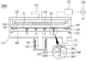
도 14 및 도 15를 참조하면, 본 발명의 제 3 실시 예에 따른 기판 처리 장치(300)는 챔버(110), RF 전력이 공급되는 고주파 전극부(120), 기판(S)을 지지하는 기판 지지 프레임(130), 챔버(110)의 내벽에 설치되어 기판 지지 프레임(130)을 지지하는 복수의 프레임 지지 부재(170), 기판 지지 프레임(130)과 기판(S)을 공정 위치 또는 기판 출입 위치로 승강시키는 서셉터(340), 서셉터(140)를 관통하도록 배치되어 기판 출입시 기판 지지 프레임(130)에 지지되는 복수의 기판(S1 내지 S4)의 일측 가장자리 부분을 제외한 나머지 타측 가장자리 부분을 지지하는 복수의 기판 지지 부재(380), 기판(S) 상에 공정 가스를 분사하는 가스 분사 수단(150), 및 기판 지지 프레임(130)에 형성되어 가스 분사 수단(150)으로부터 기판(S) 상에 분사되는 공정 가스의 흐름을 조절하는 가스 흐름 조절 수단(160)을 포함하여 구성된다.14 and 15, the
상기의 구성을 가지는 본 발명의 제 3 실시 예에 따른 기판 처리 장치(300)는 서셉터(340)와 복수의 기판 지지 부재(380)를 제외한 나머지 구성들은 상술한 본 발명의 제 1 실시 예에 따른 기판 처리 장치(100)와 동일하므로 동일한 구성들에 대한 설명은 상술한 설명으로 대신하기로 하고, 이하 동일한 도면 부호를 부여하기로 한다.In the
먼저, 기판 지지 프레임(130)은 외부의 기판 로딩 장치로부터 챔버(110)의 내부로 로딩되는 4장의 기판(S1 내지 S4) 각각의 일측 가장자리 부분을 지지하는 것을 제외하고는 상술한 본 발명의 제 1 실시 예에 따른 기판 처리 장치(100)와 동일하다.First, except that the
서셉터(340)는 베이스 부재(142), 기판 안착부(144), 및 복수의 관통 홀(342)을 포함하여 구성된다. 이러한 구성을 가지는 서셉터(340)는 복수의 관통 홀(342)을 제외한 나머지 구성들은 상술한 본 발명의 제 1 실시 예에 따른 기판 처리 장치(100)이 서셉터(140)와 동일하므로, 이들에 대한 설명은 생략하기로 하고, 이하 동일한 도면 부호를 부여하기로 한다.The
복수의 관통 홀(342) 각각은 베이스 부재(142)를 관통하도록 형성된다. 이러한 복수의 관통 홀(342) 각각에는 기판 지지 부재(380)가 삽입된다. 이를 위해, 복수의 관통 홀(342) 각각은, 도 14의 확대도와 같이, 헤드 삽입 홈(342a), 및 삽입 홀(342b)을 포함하여 구성된다.Each of the plurality of through
헤드 삽입 홈(342a)은 베이스 부재(142)의 상면으로부터 소정 깊이를 가지도록 오목하게 형성된다. 이때, 헤드 삽입 홈(342a)은 평면적으로 원 또는 사각 형태를 가지도록 형성된다.The
삽입 홀(342b)은 헤드 삽입 홈(342a)에 연통되도록 베이스 부재(142)를 관통하여 형성된다.The insertion hole 342b is formed through the
이와 같은, 서셉터(340)는 승강축(145)의 상승에 의해 상승되어 복수의 기판 지지 부재(380)에 지지된 4장의 기판(S1 내지 S4)을 지지함과 아울러 공정 위치로 상승시킨다. 이때, 4장의 기판(S1 내지 S4)은 서셉터(340)가 기판 지지 부재(380)의 위치보다 더 높게 상승할 경우 서셉터(340)의 상면에 안착됨으로써 서셉터(340)의 상승과 함께 공정 위치로 이송된다. 또한, 서셉터(340)는, 도 16에 도시된 바와 같이, 승강축(145)의 하강에 의해 하강되어 공정 위치에 있는 4장의 기판(S1 내지 S4)이 복수의 기판 지지 부재(380)과 기판 지지 프레임(130)에 안착되도록 4장의 기판(S1 내지 S4)을 기판 출입 위치로 하강시킨다. 서셉터(340)의 하강시 기판 지지 프레임(130)은 복수의 프레임 지지 부재(170)에 지지되어 기판 출입 위치에 위치하게 된다.As described above, the
복수의 기판 지지 부재(380) 각각은 서셉터(340)를 관통하도록 챔버(110) 내부에 배치되어 기판 출입시 기판 지지 프레임(130)에 지지되는 4장의 기판(S1 내지 S4) 각각의 일측 가장자리 부분을 제외한 나머지 타측 가장자리 부분을 지지한다. 이러한 복수의 기판 지지 부재(380) 각각의 상면은 기판 처리 공정시 서셉터(340)에 지지된 기판(S1 내지 S4)의 배면과 소정 거리로 이격되도록 서셉터(340)의 헤드 삽입 홈(342a)에 삽입될 수 있다. 이를 위해, 복수의 기판 지지 부재(380)는, 도 14의 확대도와 같이, 지지대(382) 및 헤드부(384)를 포함하여 구성된다.Each of the plurality of
지지대(382)는 소정 길이를 가지도록 수직하게 형성되어 서셉터(340)에 형성된 관통 홀(342)의 삽입 홀(342b)에 관통하도록 삽입된다.The
헤드부(384)는 지지대(382)의 상면에 결합되어 서셉터(340)의 헤드 삽입 홈(342a)에 삽입된다. 이때, 헤드부(384)는 서셉터(340)의 헤드 삽입 홈(342a)과 동일한 형태를 가지도록 형성되되 헤드 삽입 홈(342a)보다 작은 면적으로 가지도록 형성됨과 아울러 헤드 삽입 홈(342a)의 깊이보다 낮은 높이를 가지도록 형성된다. 그리고, 헤드부(384)의 상면은 평면 또는 곡면 형태를 가질 수 있다.The
상기의 지지대(382)와 헤드부(384)는 서로 동일한 재질로 이루어져 하나의 몸체로 일체화될 수 있다. 예를 들어, 지지대(382)와 헤드부(384)는 서셉터(340)와 동일한 재질 또는 알루미늄 재질로 이루어질 수 있다.The
상기의 지지대(382)와 헤드부(384)는 서로 다른 재질로 이루어질 수 있다. 예를 들어, 헤드부(384)는 서셉터(340)와 동일한 재질 또는 알루미늄 재질로 이루어지고, 지지대(382)는 세라믹 재질로 이루어질 수 있다.The
한편, 복수의 기판 지지 부재(380)는 지지대(382)의 하부에 결합되어 지지대(382)의 무게 중심을 형성하는 중량 부재(386)를 더 포함하여 구성된다.On the other hand, the plurality of
중량 부재(386)는 서셉터(340)의 상승시, 도 14에 도시된 바와 같이, 서셉터(340)와 함께 상승되어 챔버(110)의 바닥면으로부터 소정 높이로 상승되어 지지대(382)의 무게 중심을 잡는 무게 추의 역할을 하고, 서셉터(340)의 하강시, 도 16에 도시된 바와 같이, 챔버(110)의 바닥면에 안착되어 지지대(382)를 수직하게 지지하는 받침대의 역할을 한다.When the
상술한 바와 같은, 본 발명의 제 3 실시 예에 따른 기판 처리 장치(300)를 이용한 기판 처리 방법은 기판 지지 프레임(130)과 복수의 기판 지지 부재(380)를 이용하여 4장의 기판(S1 내지 S4)을 지지하는 것을 제외하고는 상술한 본 발명의 제 1 실시 예에 따른 기판 처리 장치(100)를 이용한 기판 처리 방법과 동일하므로 이에 대한 설명은 상술한 설명으로 대신하기로 한다.As described above, in the substrate processing method using the
따라서, 본 발명의 제 3 실시 예에 따른 기판 처리 장치(300)를 이용한 기판 처리 방법은 본 발명의 제 1 실시 예에 따른 기판 처리 장치(100)를 이용한 기판 처리 방법과 동일한 효과를 제공한다.Therefore, the substrate processing method using the
한편, 상술한 본 발명의 제 3 실시 예에 따른 기판 처리 장치(300)의 서셉터(340)와 복수의 기판 지지 부재(380)는 도 9 내지 도 13에 도시된 본 발명의 제 3 실시 예에 따른 기판 처리 장치(200)에도 동일하게 사용될 수 있다.Meanwhile, the
도 17은 본 발명의 제 4 실시 예에 따른 기판 처리 장치를 설명하기 위한 도면이고, 도 18은 도 17에 도시된 "B" 부분을 확대하여 나타내는 확대도이다.FIG. 17 is a diagram for describing a substrate processing apparatus according to a fourth exemplary embodiment of the present invention, and FIG. 18 is an enlarged view showing an enlarged portion “B” shown in FIG. 17.
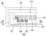
도 17 및 도 18을 참조하면, 본 발명의 제 4 실시 예에 따른 기판 처리 장치(400)는 챔버(110), RF 전력이 공급되는 고주파 전극부(120), 기판(S)을 지지하는 기판 지지 프레임(130), 챔버(110)의 내벽에 설치되어 기판 지지 프레임(130)을 지지하는 복수의 프레임 지지 부재(170), 기판 지지 프레임(130)과 기판(S)을 공정 위치 또는 기판 출입 위치로 승강시키는 서셉터(140), 기판(S) 상에 공정 가스를 분사하는 가스 분사 수단(150), 및 가스 분사 수단(150)에 형성되어 가스 분사 수단(150)으로부터 기판(S) 상에 분사되는 공정 가스의 흐름을 조절하는 가스 흐름 조절 수단(460)을 포함하여 구성된다.17 and 18, a
상기의 구성을 가지는 본 발명의 제 4 실시 예에 따른 기판 처리 장치(400)는 가스 흐름 조절 수단(460)을 제외한 나머지 구성들은 상술한 본 발명의 제 1 실시 예에 따른 기판 처리 장치(100)와 동일하므로 동일한 구성들에 대한 설명은 상술한 설명으로 대신하기로 하고, 이하 동일한 도면 부호를 부여하기로 한다.In the
가스 흐름 조절 수단(460)은 기판(S)의 가장자리 부분에 상대적으로 가깝도록 가스 분사 수단(150)의 가장자리 부분에 소정 높이로 설치되어 가스 분사 수단(150)으로부터 기판(S)의 가장자리 부분에 분사되는 공정 가스의 흐름을 조절한다. 즉, 가스 흐름 조절 수단(460)은 기판(S)의 가장자리 부분에 분사되는 공정 가스의 분사 거리(d1)를 기판(S)의 중앙 부분에 분사되는 공정 가스의 분사 거리(d2)보다 짧게 한다. 이에 따라, 가스 흐름 조절 수단(460)은 기판(S)의 가장자리 부분에 대한 가스(또는 플라즈마) 반응 시간이 증가시킴으로써 기판(S)의 가장자리 부분의 박막 증착(또는 식각)율이 상대적으로 증가하게 된다. 이를 위해, 가스 흐름 조절 수단(460)은 가스 분사 블록(462), 및 가스 분사 홀(464)을 포함하여 구성된다.The gas flow adjusting means 460 is installed at a predetermined height at the edge portion of the gas injecting means 150 so as to be relatively close to the edge portion of the substrate S, so that the gas flow adjusting means 460 is disposed at the edge portion of the substrate S from the gas injecting means 150. Regulate the flow of process gas being injected. That is, the gas flow adjusting means 460 makes the injection distance d1 of the process gas injected to the edge portion of the substrate S shorter than the injection distance d2 of the process gas injected to the center portion of the substrate S. . Accordingly, the gas flow control means 460 increases the gas (or plasma) reaction time for the edge portion of the substrate S so that the rate of thin film deposition (or etching) at the edge portion of the substrate S is relatively increased. do. To this end, the gas flow adjusting means 460 includes a
가스 분사 블록(464)은 가스 분사 수단(150)의 가장자리 부분에 소정 높이를 가지도록 설치된다. 이때, 가스 분사 블록(464)의 높이는 기판(S)의 가장자리 부분에 분사되는 공정 가스의 분사 거리(d1)가 기판(S)의 중앙 부분에 분사되는 공정 가스의 분사 거리(d2)의 절반 이하(d2/2 > d1)이 되도록 설정된다.The
가스 분사 홀(464)은 가스 분사 수단(150)에 형성된 가스 샤워 홀(156)에 중첩되도록 형성되어 가스 확산 공간(154)으로부터 가스 샤워 홀(156)을 통해 공급되는 공정 가스를 기판(S)의 가장자리 부분에 분사한다.The
가스 흐름 조절 수단(460)은 가스 분사 블록(464)을 통해 공정 가스가 기판(S)의 중앙 부분보다 먼저 기판(S)의 가장자리 부분에 분사되도록 하여 기판(S)의 가장자리 부분 상부에서의 가스 흐름을 정체시킴으로써 공정 가스가 기판(S)의 가장자리 부분 상에서 머무는 시간을 증가시킨다. 즉, 가스 분사 블록(464)의 가스 분사 홀(464)에서 분사되는 공정 가스와 가스 분사 수단(150)의 가스 샤워 홀(156)에서 분사되는 공정 가스의 압력 차이로 인하여 챔버(110)의 배기구(112)로 흐르는 가스 흐름이 기판(S)의 가장자리 부분 상부에서 정체되게 된다. 이에 따라, 가스 흐름 조절 수단(460)은 기판(S)의 가장자리 부분에 대한 가스(또는 플라즈마) 반응 시간을 증가시킴으로써 기판(S)의 가장자리 부분의 박막 증착(또는 식각)율을 상대적으로 증가시켜 기판(S) 전체 영역에 대한 기판 처리 공정의 균일도를 향상시킨다.The gas flow adjusting means 460 causes the process gas to be injected into the edge portion of the substrate S before the center portion of the substrate S through the
상술한 바와 같은 본 발명의 제 4 실시 예에 따른 기판 처리 장치(400)를 이용한 기판 처리 방법을 설명하면 다음과 같다.A substrate processing method using the
먼저, 기판 출입 위치에 위치된 기판 지지 프레임(130)을 이용하여 기판 출입 위치로 로딩되는 기판(S)을 지지한다.First, the substrate S loaded to the substrate entrance position is supported using the
그런 다음, 챔버(110) 내부의 반응 공간에 설치된 서셉터(140)를 상승시켜 기판 지지 프레임(130)과 기판(S)을 공정 위치에 위치시킨다.Then, the
그런 다음, 챔버(110) 내부에 진공 분위기를 형성한 후, 기판(S) 상에 공정 가스를 분사함과 아울러 챔버(110)의 상부에 설치된 고주파 전극부(120)에 RF 전력을 공급함으로써 반응 공간에 플라즈마를 발생시켜 기판(S)에 대한 기판 처리 공정을 수행한다. 상기의 기판 처리 공정에서 기판(S) 상에 분사되는 공정 가스의 흐름은 가스 분사 수단(150)에 설치된 가스 흐름 조절 수단(460)에 의해 조절된다. 이때, 가스 흐름 조절 수단(460)은 가스 분사 블록(462)에 형성된 가스 분사 홀(464)을 통해 기판(S)의 가장자리 부분 상부에서의 가스 흐름을 정체시킴으로써 공정 가스가 기판(S)의 가장자리 부분 상에서 머무는 시간을 증가시킨다. 이에 따라, 상기의 기판 처리 공정에서는 가스 흐름 조절 수단(460)에 의해 기판(S)의 가장자리 부분에 대한 가스(또는 플라즈마) 반응 시간이 증가됨으로써 기판(S)의 가장자리 부분의 박막 증착(또는 식각)율이 상대적으로 증가하게 된다.Then, after forming a vacuum atmosphere inside the
따라서, 본 발명의 제 4 실시 예에 따른 기판 처리 장치(400)를 이용한 기판 처리 방법은 가스 흐름 조절 수단(460)에 의한 공정 가스의 흐름 조절을 통해 기판(S)의 가장자리 부분의 박막 증착(또는 식각)율을 증가시킴으로써 기판(S) 전체 영역에 대한 기판 처리 공정의 균일도를 향상시킬 수 있다.Therefore, in the substrate processing method using the
또한, 기판 상에 소정 두께를 박막을 증착하는데 있어서, 본 발명의 제 4 실시 예에 따른 기판 처리 장치(400)를 이용한 기판 처리 방법은 공정 가스의 흐름을 제어하여 대면적 기판에 대한 기판 처리 공정의 균일도를 향상시킬 수 있다.In addition, in depositing a thin film having a predetermined thickness on a substrate, the substrate processing method using the
한편, 본 발명의 제 4 실시 예에 따른 기판 처리 장치(400)는 상술한 본 발명의 제 3 실시 예에 따른 기판 처리 장치(300)의 복수의 기판 지지 부재(380; 도 14 내지 도 16 참조)를 더 포함하여 구성될 수 있으며, 이 경우, 본 발명의 제 4 실시 예에 따른 기판 처리 장치(400)는 상술한 서셉터(140) 대신에 상술한 본 발명의 제 3 실시 예에 따른 기판 처리 장치(300)의 서셉터(340)를 포함하여 구성된다.Meanwhile, the
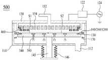
도 19는 본 발명의 제 5 실시 예에 따른 기판 처리 장치를 설명하기 위한 도면이다.19 is a diagram for describing a substrate processing apparatus according to a fifth embodiment of the present invention.
도 19를 참조하면, 본 발명의 제 5 실시 예에 따른 기판 처리 장치(500)는 챔버(110), RF 전력이 공급되는 고주파 전극부(120), 기판(S)을 지지하는 기판 지지 프레임(130), 챔버(110)의 내벽에 설치되어 기판 지지 프레임(130)을 지지하는 복수의 프레임 지지 부재(170), 기판 지지 프레임(130)과 기판(S)을 공정 위치 또는 기판 출입 위치로 승강시키는 서셉터(340), 서셉터(340)를 관통하도록 배치되어 기판 출입시 기판 지지 프레임(130)에 지지되는 복수의 기판(S1 내지 S4)의 일측 가장자리 부분을 제외한 나머지 타측 가장자리 부분을 지지하는 복수의 기판 지지 부재(380), 기판(S) 상에 공정 가스를 분사하는 가스 분사 수단(150), 기판 지지 프레임(130)에 형성되어 가스 분사 수단(150)으로부터 기판(S) 상에 분사되는 공정 가스의 흐름을 조절하는 제 1 가스 흐름 조절 수단(160/260/1260), 및 가스 분사 수단(150)에 형성되어 가스 분사 수단(150)으로부터 기판(S) 상에 분사되는 공정 가스의 흐름을 조절하는 제 2 가스 흐름 조절 수단(460)을 포함하여 구성된다.Referring to FIG. 19, the
상기의 구성을 가지는 본 발명의 제 5 실시 예에 따른 기판 처리 장치(500)는 상술한 본 발명의 제 1, 제 2, 또는 제 3 실시 예와 본 발명의 제 4 실시 예를 결합한 것이다. 즉, 본 발명의 제 5 실시 예에 따른 기판 처리 장치(500)는 상술한 제 1, 제 2, 또는 제 3 실시 예에서와 같이 기판 지지 프레임(130)에 설치된 가스 흐름 조절 수단(160/260/1260)과 상술한 제 4 실시 예에서와 같이 가스 분사 수단(150)에 설치된 가스 흐름 조절 수단(460)을 모두 포함하도록 구성된다. 이에 따라, 본 발명의 제 5 실시 예에 따른 기판 처리 장치(500)에 대한 설명은 상술한 설명으로 대신하기로 한다.The
이와 같은, 본 발명의 제 5 실시 예에 따른 기판 처리 장치(500)를 이용한 기판 처리 방법은 기판 지지 프레임(130)에 형성된 제 1 가스 흐름 조절 수단(160/260/1260)과 가스 분사 수단(150)에 형성된 제 2 가스 흐름 조절 수단(460)을 이용하여 공정 가스의 흐름을 조절하는 것을 제외하고는 본 발명의 제 1 실시 예에 따른 기판 처리 장치(100)를 이용한 기판 처리 방법과 동일하므로 이에 대한 설명은 상술한 설명으로 대신하기로 한다.As described above, in the substrate processing method using the
따라서, 본 발명의 제 5 실시 예에 따른 기판 처리 장치(500)를 이용한 기판 처리 방법은 제 1 및 제 2 가스 흐름 조절 수단(160/260/1260, 460)에 의한 공정 가스의 흐름 조절을 통해 기판(S)의 가장자리 부분의 박막 증착(또는 식각)율을 증가시킴으로써 기판(S) 전체 영역에 대한 기판 처리 공정의 균일도를 더욱 향상시킬 수 있다. 또한, 기판 상에 소정 두께를 박막을 증착하는데 있어서, 본 발명의 제 5 실시 예에 따른 기판 처리 장치(500)를 이용한 기판 처리 방법은 공정 가스의 흐름을 제어하여 대면적 기판에 대한 기판 처리 공정의 균일도를 향상시킬 수 있다.Therefore, in the substrate processing method using the
도 20은 본 발명의 제 6 실시 예에 따른 기판 처리 장치를 설명하기 위한 도면이고, 도 21은 도 20에 도시된 "C" 부분을 확대하여 나타내는 확대도이다.FIG. 20 is a diagram for describing a substrate processing apparatus according to a sixth embodiment of the present invention, and FIG. 21 is an enlarged view showing an enlarged portion "C" shown in FIG. 20.
도 20 및 도 21을 참조하면, 본 발명의 제 6 실시 예에 따른 기판 처리 장치(500)는 챔버(110), RF 전력이 공급되는 고주파 전극부(120), 기판(S)을 지지하는 기판 지지 프레임(130), 챔버(110)의 내벽에 설치되어 기판 지지 프레임(130)을 지지하는 복수의 프레임 지지 부재(170), 기판 지지 프레임(130)과 기판(S)을 공정 위치 또는 기판 출입 위치로 승강시키는 서셉터(140), 기판(S) 상에 공정 가스를 분사하는 가스 분사 수단(150), 및 가스 분사 수단(150)의 가장자리 부분에 설치되어 가스 분사 수단(150)으로부터 기판(S) 상에 분사되는 공정 가스의 흐름을 조절하는 가스 흐름 조절 수단(560)을 포함하여 구성된다.20 and 21, the
상기의 구성을 가지는 본 발명의 제 6 실시 예에 따른 기판 처리 장치(500)는 가스 흐름 조절 수단(560)을 제외한 나머지 구성들은 상술한 본 발명의 제 1 실시 예에 따른 기판 처리 장치(100)와 동일하므로 동일한 구성들에 대한 설명은 상술한 설명으로 대신하기로 하고, 이하 동일한 도면 부호를 부여하기로 한다.In the
가스 흐름 조절 수단(560)은 서셉터(140)의 가장자리 부분에 가깝도록 가스 분사 수단(150)의 가장자리 부분에 소정 높이를 가지도록 설치되어 가스 분사 수단(150)으로부터 기판(S) 상에 분사된 기판(S) 상의 가스 흐름을 조절한다. 이를 위해, 가스 흐름 조절 수단(560)은 블록 지지부(562), 및 가스 정체 블록(564)을 포함하여 구성된다.The gas flow control means 560 is installed to have a predetermined height at the edge portion of the gas injection means 150 so as to be close to the edge portion of the
블록 지지부(562)는 평판 형태로 형성되어 결합 부재(예를 들어, 볼트 또는 스크류)(미도시)에 의해 가스 분사 수단(150)의 가장자리 부분에 설치되어 가스 정체 블록(564)을 지지한다.The
가스 정체 블록(564)은 서셉터(140)의 가장자리 부분에 대향되도록 블록 지지부(562)의 하부에 소정의 높이를 가지도록 수직하게 설치된다. 이에 따라, 공정 위치에 위치한 기판(S)과 가스 정체 블록(564) 간의 거리(d3)는 공정 위치에 위치한 기판(S)과 가스 분사 수단(150) 간의 거리(d2)보다 상대적으로 가깝게 된다. 이러한 가스 정체 블록(564)은, 기판 처리 공정시, 기판(S) 상의 공정 가스가 챔버(110)의 배기구(112)로 흐르는 공간을 좁게 하여 기판(S)의 가장자리 부분에서의 가스 흐름을 정체시킨다.The
이와 같은, 가스 흐름 조절 수단(560)은, 기판 처리 공정시, 가스 정체 블록(564)을 통해 기판(S)의 가장자리 부분 상부에서의 가스 흐름을 정체시켜 공정 가스가 기판(S)의 가장자리 부분 상에서 머무는 시간을 증가시킨다. 이에 따라, 기판(S)의 가장자리 부분에 대한 가스 반응 시간이 증가되어 기판(S)의 가장자리 부분의 박막 증착(또는 식각)율을 상대적으로 증가됨으로써 기판(S) 전체 영역에 대한 기판 처리 공정의 균일도가 향상된다.As such, the gas flow adjusting means 560 stagnates the gas flow in the upper portion of the edge portion of the substrate S through the
상술한 바와 같은 본 발명의 제 6 실시 예에 따른 기판 처리 장치(500)를 이용한 기판 처리 방법을 설명하면 다음과 같다.A substrate processing method using the
먼저, 기판 출입 위치에 위치된 기판 지지 프레임(130)을 이용하여 기판 출입 위치로 로딩되는 기판(S)을 지지한다.First, the substrate S loaded to the substrate entrance position is supported using the
그런 다음, 챔버(110) 내부의 반응 공간에 설치된 서셉터(140)를 상승시켜 기판 지지 프레임(130)과 기판(S)을 공정 위치에 위치시킨다.Then, the
그런 다음, 챔버(110) 내부에 진공 분위기를 형성한 후, 기판(S) 상에 공정 가스를 분사함과 아울러 챔버(110)의 상부에 설치된 고주파 전극부(120)에 RF 전력을 공급함으로써 반응 공간에 플라즈마를 발생시켜 기판(S)에 대한 기판 처리 공정을 수행한다. 상기의 기판 처리 공정에서 기판(S) 상에 분사되는 공정 가스의 흐름은 가스 흐름 조절 수단(560)의 가스 정체 블록(564)에 의해 조절되어 기판(S)의 가장자리 부분 상에서 오랜 시간 머무르게 된다. 이에 따라, 상기의 기판 처리 공정에서는 가스 흐름 조절 수단(560)에 의해 기판(S)의 가장자리 부분에 대한 가스 반응 시간이 증가됨으로써 기판(S)의 가장자리 부분의 박막 증착(또는 식각)율이 상대적으로 증가하게 된다.Then, after forming a vacuum atmosphere inside the
따라서, 본 발명의 제 6 실시 예에 따른 기판 처리 장치(500)를 이용한 기판 처리 방법은 가스 흐름 조절 수단(560)에 의한 공정 가스의 흐름 조절을 통해 기판(S)의 가장자리 부분의 박막 증착(또는 식각)율을 증가시킴으로써 기판(S) 전체 영역에 대한 기판 처리 공정의 균일도를 향상시킬 수 있다.Therefore, in the substrate processing method using the
또한, 기판 상에 소정 두께를 박막을 증착하는데 있어서, 본 발명의 제 6 실시 예에 따른 기판 처리 장치(500)를 이용한 기판 처리 방법은 공정 가스의 흐름을 제어하여 대면적 기판에 대한 기판 처리 공정의 균일도를 향상시킬 수 있다.In addition, in depositing a thin film having a predetermined thickness on a substrate, the substrate processing method using the
한편, 본 발명의 제 6 실시 예에 따른 기판 처리 장치(500)는 상술한 본 발명의 제 3 실시 예에 따른 기판 처리 장치(300)의 복수의 기판 지지 부재(380; 도 14 내지 도 16 참조)를 더 포함하여 구성될 수 있으며, 이 경우, 본 발명의 제 6 실시 예에 따른 기판 처리 장치(500)는 상술한 서셉터(140) 대신에 상술한 본 발명의 제 3 실시 예에 따른 기판 처리 장치(300)의 서셉터(340)를 포함하여 구성된다.On the other hand, the
도 22는 본 발명의 제 7 실시 예에 따른 기판 처리 장치를 설명하기 위한 도면이다.FIG. 22 is a diagram for describing a substrate processing apparatus according to a seventh embodiment.
도 22를 참조하면, 본 발명의 제 7 실시 예에 따른 기판 처리 장치(600)는 챔버(110), RF 전력이 공급되는 고주파 전극부(120), 기판(S)을 지지하는 기판 지지 프레임(130), 챔버(110)의 내벽에 설치되어 기판 지지 프레임(130)을 지지하는 복수의 프레임 지지 부재(170), 기판 지지 프레임(130)과 기판(S)을 공정 위치 또는 기판 출입 위치로 승강시키는 서셉터(340), 서셉터(340)를 관통하도록 배치되어 기판 출입시 기판 지지 프레임(130)에 지지되는 복수의 기판(S1 내지 S4)의 일측 가장자리 부분을 제외한 나머지 타측 가장자리 부분을 지지하는 복수의 기판 지지 부재(380), 기판(S) 상에 공정 가스를 분사하는 가스 분사 수단(150), 기판 지지 프레임(130)에 형성되어 가스 분사 수단(150)으로부터 기판(S) 상에 분사되는 공정 가스의 흐름을 조절하는 제 1 가스 흐름 조절 수단(160/260/1260), 및 가스 분사 수단(150)에 형성되어 가스 분사 수단(150)으로부터 기판(S) 상에 분사되는 공정 가스의 흐름을 조절하는 제 2 가스 흐름 조절 수단(560)을 포함하여 구성된다.Referring to FIG. 22, the
상기의 구성을 가지는 본 발명의 제 7 실시 예에 따른 기판 처리 장치(600)는 상술한 본 발명의 제 1, 제 2, 또는 제 3 실시 예와 본 발명의 제 6 실시 예를 결합한 것이다. 즉, 본 발명의 제 7 실시 예에 따른 기판 처리 장치(600)는 상술한 제 1, 제 2, 또는 제 3 실시 예에서와 같이 기판 지지 프레임(130)에 설치된 가스 흐름 조절 수단(160/260/1260)과 상술한 제 6 실시 예에서와 같이 가스 분사 수단(150)에 설치된 가스 흐름 조절 수단(560)을 모두 포함하도록 구성된다. 이에 따라, 본 발명의 제 7 실시 예에 따른 기판 처리 장치(600)에 대한 설명은 상술한 설명으로 대신하기로 한다.The
이와 같은, 본 발명의 제 7 실시 예에 따른 기판 처리 장치(600)는 기판 지지 프레임(130)에 형성된 제 1 가스 흐름 조절 수단(160/260/1260)과 가스 분사 수단(150)에 형성된 제 2 가스 흐름 조절 수단(560)이 서로 대향됨으로써 기판(S) 상의 공정 가스가 챔버(110)의 배기구(112)로 흐르는 공간(d4)을 더욱 좁게 하여 기판(S)의 가장자리 부분에서의 가스 흐름을 더욱 정체시킬 수 있다.As described above, the
상술한 본 발명의 제 7 실시 예에 따른 기판 처리 장치(600)를 이용한 기판 처리 방법은 기판 지지 프레임(130)에 형성된 제 1 가스 흐름 조절 수단(160/260/1260)과 제 1 가스 흐름 조절 수단(160/260/1260)에 마주보도록 고주파 전극부(120)에 형성된 제 2 가스 흐름 조절 수단(560)을 이용하여 공정 가스의 흐름을 조절하는 것을 제외하고는 본 발명의 제 1 실시 예에 따른 기판 처리 장치(100)를 이용한 기판 처리 방법과 동일하므로 이에 대한 설명은 상술한 설명으로 대신하기로 한다.Substrate processing method using the
따라서, 본 발명의 제 7 실시 예에 따른 기판 처리 장치(600)를 이용한 기판 처리 방법은 제 1 및 제 2 가스 흐름 조절 수단(160/260/1260, 560)에 의한 공정 가스의 흐름 조절을 통해 기판(S)의 가장자리 부분의 박막 증착(또는 식각)율을 증가시킴으로써 기판(S) 전체 영역에 대한 기판 처리 공정의 균일도를 더욱 향상시킬 수 있다. 또한, 기판 상에 소정 두께를 박막을 증착하는데 있어서, 본 발명의 제 7 실시 예에 따른 기판 처리 장치(600)를 이용한 기판 처리 방법은 공정 가스의 흐름을 제어하여 대면적 기판에 대한 기판 처리 공정의 균일도를 향상시킬 수 있다.Therefore, in the substrate processing method using the
한편, 상술한 본 발명의 제 1 내지 제 7 실시 예에 따른 기판 처리 장치에서는 고주파 전극부(120)에 인가되는 고주파 전력과 공정 공간에 인가되는 공정 가스를 이용해 공정 공간에 플라즈마를 형성함으로써 기판(S)에 박막을 증착하거나 기판(S) 상의 박막을 식각하는 것으로 설명하였으나, 이에 한정되지 않고, 플라즈마를 이용하지 않고 공정 가스에 기초하여 기판 처리 공정을 수행하는 기판 처리 장치에도 동일하게 적용될 수 있다. 예를 들어, 플라즈마를 이용하지 않는 기판 처리 장치는 MOCVD(Metal Organic Chemical Vapor Deposition) 장치가 될 수 있다.Meanwhile, in the above-described substrate processing apparatuses according to the first to seventh embodiments of the present invention, a plasma is formed in a process space by using a high frequency power applied to the high
본 발명이 속하는 기술분야의 당업자는 본 발명이 그 기술적 사상이나 필수적 특징을 변경하지 않고서 다른 구체적인 형태로 실시될 수 있다는 것을 이해할 수 있을 것이다. 그러므로, 이상에서 기술한 실시 예들은 모든 면에서 예시적인 것이며 한정적인 것이 아닌 것으로 이해해야만 한다. 본 발명의 범위는 상기 상세한 설명보다는 후술하는 특허청구범위에 의하여 나타내어지며, 특허청구범위의 의미 및 범위 그리고 그 등가 개념으로부터 도출되는 모든 변경 또는 변형된 형태가 본 발명의 범위에 포함되는 것으로 해석되어야 한다.It will be understood by those skilled in the art that the present invention may be embodied in other specific forms without departing from the spirit or essential characteristics thereof. It is therefore to be understood that the above-described embodiments are illustrative in all aspects and not restrictive. The scope of the present invention is defined by the appended claims rather than the detailed description and all changes or modifications derived from the meaning and scope of the claims and their equivalents are to be construed as being included within the scope of the present invention do.
110: 챔버 120: 고주파 전극부
130: 기판 지지 프레임 140, 340: 서셉터
150: 가스 분사 수단 170: 프레임 지지 부재
162: 돌출부 266: 높이 조절부
380: 기판 지지 부재
160, 260, 460, 560, 1260: 가스 흐름 조절 수단
262a, 262b, 262c, 262d, 1262, 1264: 가스 정체 프레임110: chamber 120: high frequency electrode portion
130:
150: gas injection means 170: frame support member
162: protrusion 266: height adjustment
380: substrate support member
160, 260, 460, 560, 1260: gas flow control means
262a, 262b, 262c, 262d, 1262, 1264: gas stagnation frame
Claims (20)
Translated fromKorean상기 챔버 내부의 기판 출입 위치에 설치되어 적어도 하나의 기판을 지지하는 기판 지지 프레임;
상기 기판 지지 프레임과 상기 기판을 공정 위치 또는 상기 기판 출입 위치로 승강시키는 서셉터;
상기 서셉터의 상부에 설치되어 상기 기판 상에 공정 가스를 분사하는 가스 분사 수단; 및
상기 가스 분사 수단으로부터 상기 기판 상에 분사되어 상기 배기구로 흐르는 공정 가스의 흐름을 상기 기판의 가장자리 부분에서 정체시키는 가스 흐름 조절 수단을 포함하며,
상기 가스 흐름 조절 수단은 상기 기판 지지 프레임에 지지된 상기 기판의 높이보다 더 높은 높이를 가지도록 상기 기판 지지 프레임으로부터 돌출되어 상기 기판의 측면에 마주보는 돌출부, 및 상기 돌출부의 높이를 증가시키기 위한 높이 조절부를 포함하여 구성되며,
상기 높이 조절부는,
상기 돌출부에 형성된 승강 가이드 홈;
상기 승강 가이드 홈에 승강 가능하게 삽입된 승강 블록; 및
상기 기판 지지 프레임의 배면에 설치되어 상기 승강 블록을 상기 승강 가이드 홈 내에서 승강시켜 상기 돌출부의 높이를 증가시키는 블록 승강 부재를 포함하여 구성되는 것을 특징으로 하는 기판 처리 장치.A chamber having a process space for a substrate processing process and an exhaust port communicating with the process space;
A substrate support frame installed at a substrate entrance position in the chamber to support at least one substrate;
A susceptor for elevating the substrate support frame and the substrate to a process position or the substrate entrance position;
Gas injection means installed on an upper portion of the susceptor to inject a process gas onto the substrate; And
Gas flow control means for stagnating the flow of the process gas injected from the gas injecting means onto the substrate to the exhaust port at an edge portion of the substrate,
The gas flow adjusting means may protrude from the substrate support frame to have a height higher than the height of the substrate supported by the substrate support frame, and a protrusion facing the side of the substrate, and a height for increasing the height of the protrusion. It is configured to include a control unit,
The height adjuster includes:
Lifting guide grooves formed in the protrusions;
An elevating block inserted into the elevating guide groove so as to elevate; And
And a block elevating member disposed on a rear surface of the substrate supporting frame to elevate the elevating block in the elevating guide groove to increase the height of the protrusion.
상기 챔버 내부의 기판 출입 위치에 설치되어 적어도 하나의 기판을 지지하는 기판 지지 프레임;
상기 기판 지지 프레임과 상기 기판을 공정 위치 또는 상기 기판 출입 위치로 승강시키는 서셉터;
상기 서셉터의 상부에 설치되어 상기 기판 상에 공정 가스를 분사하는 가스 분사 수단; 및
상기 가스 분사 수단으로부터 상기 기판 상에 분사되어 상기 배기구로 흐르는 공정 가스의 흐름을 조절하는 가스 흐름 조절 수단을 포함하며,
상기 가스 흐름 조절 수단은 상기 기판 지지 프레임에 지지된 상기 기판의 높이보다 더 높은 높이로 형성되어 상기 기판의 측면에 마주보도록 상기 기판 지지 프레임에 설치된 가스 정체 프레임을 포함하여 구성되는 것을 특징으로 하는 기판 처리 장치.A chamber having a process space for a substrate processing process and an exhaust port communicating with the process space;
A substrate support frame installed at a substrate entrance position in the chamber to support at least one substrate;
A susceptor for elevating the substrate support frame and the substrate to a process position or the substrate entrance position;
Gas injection means installed on an upper portion of the susceptor to inject a process gas onto the substrate; And
Gas flow control means for controlling a flow of process gas injected from the gas injection means onto the substrate and flowing to the exhaust port,
The gas flow adjusting means is formed to a height higher than the height of the substrate supported on the substrate support frame, characterized in that it comprises a gas retention frame installed on the substrate support frame to face the side of the substrate Processing unit.
상기 가스 흐름 조절 수단은 상기 가스 정체 프레임의 높이를 증가시키기 위한 높이 조절부를 더 포함하여 구성되며,
상기 높이 조절부는,
상기 가스 정체 프레임에 형성된 승강 가이드 홈;
상기 승강 가이드 홈에 승강 가능하게 삽입된 승강 블록; 및
상기 기판 지지 프레임의 배면에 설치되어 상기 승강 블록을 상기 승강 가이드 홈 내에서 승강시켜 상기 가스 정체 프레임의 높이를 조절하는 블록 승강 부재를 포함하여 구성되는 것을 특징으로 하는 기판 처리 장치.The method of claim 5, wherein
The gas flow control means further comprises a height adjustment for increasing the height of the gas stagnation frame,
The height adjuster includes:
A lifting guide groove formed in the gas stagnation frame;
An elevating block inserted into the elevating guide groove so as to elevate; And
And a block elevating member disposed on a rear surface of the substrate supporting frame to elevate the elevating block in the elevating guide groove to adjust the height of the gas stagnation frame.
상기 챔버 내부의 기판 출입 위치에 설치되어 적어도 하나의 기판을 지지하는 기판 지지 프레임;
상기 기판 지지 프레임과 상기 기판을 공정 위치 또는 상기 기판 출입 위치로 승강시키는 서셉터;
상기 서셉터의 상부에 설치되어 상기 기판 상에 공정 가스를 분사하는 가스 분사 수단; 및
상기 가스 분사 수단으로부터 상기 기판 상에 분사되어 상기 배기구로 흐르는 공정 가스의 흐름을 조절하는 가스 흐름 조절 수단을 포함하며,
상기 가스 흐름 조절 수단은 상기 기판 지지 프레임에 지지된 상기 기판의 높이보다 더 높은 높이로 형성되어 상기 기판의 모서리 부분에 마주보도록 상기 기판 지지 프레임의 모서리 부분 상면에 설치된 복수의 가스 정체 프레임을 포함하여 구성되는 것을 특징으로 하는 기판 처리 장치.A chamber having a process space for a substrate processing process and an exhaust port communicating with the process space;
A substrate support frame installed at a substrate entrance position in the chamber to support at least one substrate;
A susceptor for elevating the substrate support frame and the substrate to a process position or the substrate entrance position;
Gas injection means installed on an upper portion of the susceptor to inject a process gas onto the substrate; And
Gas flow control means for controlling a flow of process gas injected from the gas injection means onto the substrate and flowing to the exhaust port,
The gas flow adjusting means may include a plurality of gas stagnant frames formed at a height higher than a height of the substrate supported by the substrate support frame and installed on an edge portion of the substrate support frame so as to face an edge portion of the substrate. The substrate processing apparatus characterized by the above-mentioned.
상기 가스 흐름 조절 수단은 상기 복수의 가스 정체 프레임 각각의 높이를 증가시키기 위한 높이 조절부를 더 포함하여 구성되며,
상기 높이 조절부는,
상기 복수의 가스 정체 프레임 각각에 형성된 복수의 승강 가이드 홈;
상기 복수의 승강 가이드 홈 각각에 승강 가능하게 삽입된 복수의 승강 블록; 및
상기 기판 지지 프레임의 배면에 설치되어 상기 복수의 승강 블록 각각을 상기 복수의 승강 가이드 홈 각각의 내부에서 승강시켜 상기 복수의 가스 정체 프레임 각각의 높이를 조절하는 복수의 블록 승강 부재를 포함하여 구성되는 것을 특징으로 하는 기판 처리 장치.The method of claim 7, wherein
The gas flow adjusting means further comprises a height adjusting unit for increasing the height of each of the plurality of gas stagnation frame,
The height adjuster includes:
A plurality of lifting guide grooves formed in each of the plurality of gas stagnation frames;
A plurality of lifting blocks inserted into and liftable from each of the plurality of lifting guide grooves; And
And a plurality of block elevating members disposed on a rear surface of the substrate support frame to elevate each of the plurality of elevating blocks in each of the plurality of elevating guide grooves to adjust the height of each of the plurality of gas stagnation frames. Substrate processing apparatus, characterized in that.
상기 챔버 내부의 기판 출입 위치에 설치되어 적어도 하나의 기판을 지지하는 기판 지지 프레임;
상기 기판 지지 프레임과 상기 기판을 공정 위치 또는 상기 기판 출입 위치로 승강시키는 서셉터;
상기 서셉터의 상부에 설치되어 상기 기판 상에 공정 가스를 분사하는 가스 분사 수단; 및
상기 가스 분사 수단으로부터 상기 기판 상에 분사되어 상기 배기구로 흐르는 공정 가스의 흐름을 조절하는 가스 흐름 조절 수단을 포함하며,
상기 가스 흐름 조절 수단은 상기 기판의 가장자리 부분 쪽으로 돌출되도록 상기 가스 분사 수단의 가장자리 부분에 설치되어 상기 기판의 가장자리 부분에서의 상기 공정 가스 흐름을 정체시키는 가스 분사 블록을 포함하여 구성되는 것을 특징으로 하는 기판 처리 장치.A chamber having a process space for a substrate processing process and an exhaust port communicating with the process space;
A substrate support frame installed at a substrate entrance position in the chamber to support at least one substrate;
A susceptor for elevating the substrate support frame and the substrate to a process position or the substrate entrance position;
Gas injection means installed on an upper portion of the susceptor to inject a process gas onto the substrate; And
Gas flow control means for controlling a flow of process gas injected from the gas injection means onto the substrate and flowing to the exhaust port,
The gas flow control means is configured to include a gas injection block is installed on the edge portion of the gas injection means to protrude toward the edge portion of the substrate to stagnate the process gas flow at the edge portion of the substrate Substrate processing apparatus.
상기 챔버 내부의 기판 출입 위치에 설치되어 적어도 하나의 기판을 지지하는 기판 지지 프레임;
상기 기판 지지 프레임과 상기 기판을 공정 위치 또는 상기 기판 출입 위치로 승강시키는 서셉터;
상기 서셉터의 상부에 설치되어 상기 기판 상에 공정 가스를 분사하는 가스 분사 수단;
상기 가스 분사 수단으로부터 상기 기판 상에 분사되어 상기 배기구로 흐르는 공정 가스의 흐름을 조절하는 가스 흐름 조절 수단; 및
상기 챔버의 내벽에 설치되어 상기 서셉터의 하강시 상기 기판 지지 프레임을 지지하는 복수의 프레임 지지 부재를 포함하며,
상기 기판 지지 프레임은,
상기 서셉터의 중앙 부분을 제외한 가장자리 부분에 중첩됨과 아울러 적어도 하나의 일측 개구부를 가지도록 형성되어 상기 서셉터의 상승시 상기 서셉터의 가장자리 부분에 안착되는 제 1 기판 지지 플레이트;
상기 서셉터의 상승시 상기 적어도 하나의 일측 개구부에 삽입되어 상기 기판을 지지하도록 상기 서셉터의 일측 가장자리 부분에 설치된 적어도 하나의 제 2 기판 지지 플레이트; 및
상기 복수의 프레임 지지 부재 각각에 대응되도록 상기 제 1 기판 지지 플레이트에 형성된 복수의 지지 홀을 포함하여 구성되는 것을 특징으로 하는 기판 처리 장치.A chamber having a process space for a substrate processing process and an exhaust port communicating with the process space;
A substrate support frame installed at a substrate entrance position in the chamber to support at least one substrate;
A susceptor for elevating the substrate support frame and the substrate to a process position or the substrate entrance position;
Gas injection means installed on an upper portion of the susceptor to inject a process gas onto the substrate;
Gas flow control means for controlling a flow of process gas injected from the gas injection means onto the substrate and flowing to the exhaust port; And
A plurality of frame supporting members installed on an inner wall of the chamber and supporting the substrate supporting frame when the susceptor descends,
The substrate support frame,
A first substrate support plate overlapping an edge portion except for a center portion of the susceptor and having at least one side opening and seated on an edge portion of the susceptor when the susceptor is raised;
At least one second substrate support plate inserted in the at least one side opening to support the substrate when the susceptor is raised; And
And a plurality of support holes formed in the first substrate support plate so as to correspond to each of the plurality of frame support members.
상기 가스 흐름 조절 수단은 상기 기판 지지 프레임에 지지된 상기 기판의 높이보다 더 높은 높이를 가지도록 상기 제 1 및 제 2 기판 지지 플레이트로부터 돌출되어 상기 기판의 측면에 마주보는 돌출부를 포함하여 구성되는 것을 특징으로 하는 기판 처리 장치.11. The method of claim 10,
The gas flow control means includes a protrusion protruding from the first and second substrate support plates to face the side of the substrate to have a height higher than the height of the substrate supported by the substrate support frame. A substrate processing apparatus characterized by the above-mentioned.
상기 가스 흐름 조절 수단은 상기 기판 지지 프레임에 지지된 상기 기판의 높이보다 더 높은 높이로 형성되어 상기 기판의 측면에 마주보도록 상기 제 1 및 제 2 기판 지지 플레이트 각각에 설치된 제 1 및 제 2 가스 정체 프레임을 포함하여 구성되는 것을 특징으로 하는 기판 처리 장치.11. The method of claim 10,
The gas flow regulating means is formed at a height higher than the height of the substrate supported by the substrate support frame, the first and second gas stagnation installed on each of the first and second substrate support plates to face the side of the substrate. Substrate processing apparatus comprising a frame.
상기 가스 흐름 조절 수단은 상기 기판 지지 프레임에 지지된 상기 기판의 높이보다 더 높은 높이로 형성되어 상기 기판의 모서리 부분에 마주보도록 상기 제 1 기판 지지 플레이트의 모서리 부분 상면에 설치된 복수의 가스 정체 프레임을 포함하여 구성되는 것을 특징으로 하는 기판 처리 장치.11. The method of claim 10,
The gas flow adjusting means may include a plurality of gas stagnation frames formed at a height higher than a height of the substrate supported by the substrate support frame and installed on an upper surface of a corner portion of the first substrate support plate to face an edge portion of the substrate. Substrate processing apparatus comprising a.
상기 서셉터를 관통하도록 배치되어 상기 기판 출입시 상기 기판 지지 프레임에 지지되는 복수의 기판의 일측 가장자리 부분을 제외한 나머지 타측 가장자리 부분을 지지하는 복수의 기판 지지 부재를 더 포함하여 구성되는 것을 특징으로 하는 기판 처리 장치.The method of claim 1,
And a plurality of substrate supporting members disposed to penetrate the susceptor and supporting the other edge portions except for one edge portion of the plurality of substrates supported by the substrate support frame when the substrate enters and exits the substrate. Substrate processing apparatus.
상기 가스 흐름 조절 수단은 상기 기판의 가장자리 부분 쪽으로 돌출되도록 상기 가스 분사 수단의 가장자리 부분에 설치된 가스 분사 블록을 포함하고,
상기 가스 분사 블록은 상기 기판의 가장자리 부분에 상기 공정 가스를 분사하여 상기 기판의 가장자리 부분에서의 상기 공정 가스 흐름을 정체시키는 것을 특징으로 하는 기판 처리 장치.The method according to any one of claims 1, 5 to 8, 10 to 14,
The gas flow control means includes a gas injection block installed on the edge portion of the gas injection means to protrude toward the edge portion of the substrate,
And the gas injection block injects the process gas to an edge portion of the substrate to stagnate the process gas flow at an edge portion of the substrate.
상기 가스 흐름 조절 수단은,
상기 가스 분사 수단의 가장자리 부분에 설치된 블록 지지부; 및
상기 서셉터의 가장자리 부분 쪽으로 돌출되도록 상기 블록 지지부의 하부에 설치되어 상기 기판의 가장자리 부분에서의 상기 공정 가스 흐름을 정체시키는 가스 정체 블록을 포함하여 구성되는 것을 특징으로 하는 기판 처리 장치.The method according to any one of claims 1, 5 to 8, 10 to 14,
The gas flow control means,
A block support part provided at an edge of the gas injection means; And
And a gas retention block installed below the block support to protrude toward the edge portion of the susceptor to stagnate the process gas flow at the edge portion of the substrate.
상기 기판 지지 프레임을 상기 챔버 내부의 기판 출입 위치에 위치시키는 단계;
상기 기판 지지 프레임을 이용하여 상기 기판 출입 위치로 로딩되는 적어도 하나의 기판을 지지하는 단계;
상기 챔버 내부의 반응 공간에 설치된 서셉터를 상승시켜 상기 기판 지지 프레임과 상기 기판을 공정 위치에 위치시키는 단계; 및
상기 기판 상에 공정 가스를 분사하여 상기 공정 가스에 기초하여 이루어지는 기판 처리 공정을 수행하는 단계를 포함하여 이루어지며,
상기 기판 상에 분사되는 공정 가스의 흐름은 상기 가스 흐름 조절 수단에 의해 조절되는 것을 특징으로 하는 기판 처리 방법.Adjusting the height of the gas flow adjusting means installed in the substrate support frame disposed inside the chamber;
Positioning the substrate support frame at a substrate entry position within the chamber;
Supporting at least one substrate loaded into the substrate entrance position using the substrate support frame;
Raising the susceptor installed in the reaction space inside the chamber to position the substrate support frame and the substrate at a process position; And
And spraying a process gas on the substrate to perform a substrate processing process based on the process gas.
The flow of the process gas injected on the substrate is controlled by the gas flow control means.
상기 가스 흐름 조절 수단은 상기 기판 지지 프레임에 설치된 적어도 하나의 가스 정체 프레임과 상기 가스 정체 프레임에 승강 가능하게 설치된 승강 블록을 포함하여 구성되며,
상기 가스 흐름 조절 수단의 높이는 상기 승강 블록의 승강 높이에 따라 조절되는 것을 특징으로 하는 기판 처리 방법.The method of claim 18,
The gas flow adjusting means is configured to include at least one gas stagnation frame installed on the substrate support frame and the elevating block is mounted to the gas stagnation frame to be elevated,
And the height of the gas flow adjusting means is adjusted according to the lifting height of the lifting block.
상기 적어도 하나의 기판을 지지하는 단계는 상기 서셉터를 관통하도록 배치된 복수의 기판 지지 부재를 이용하여 상기 기판 지지 프레임에 지지되는 복수의 기판의 일측 가장자리 부분을 제외한 나머지 타측 가장자리 부분을 지지하는 단계를 포함하여 이루어지는 것을 특징으로 하는 기판 처리 방법.The method of claim 18,
The supporting of the at least one substrate may include supporting the other edge portion except for one edge portion of the plurality of substrates supported by the substrate support frame using a plurality of substrate support members disposed to penetrate the susceptor. Substrate processing method comprising a.
Priority Applications (1)
| Application Number | Priority Date | Filing Date | Title |
|---|---|---|---|
| KR1020110073793AKR101292817B1 (en) | 2011-07-25 | 2011-07-25 | Substrate processing apparatus and substrate processing method using the same |
Applications Claiming Priority (1)
| Application Number | Priority Date | Filing Date | Title |
|---|---|---|---|
| KR1020110073793AKR101292817B1 (en) | 2011-07-25 | 2011-07-25 | Substrate processing apparatus and substrate processing method using the same |
Publications (2)
| Publication Number | Publication Date |
|---|---|
| KR20130012515A KR20130012515A (en) | 2013-02-04 |
| KR101292817B1true KR101292817B1 (en) | 2013-08-02 |
Family
ID=47893197
Family Applications (1)
| Application Number | Title | Priority Date | Filing Date |
|---|---|---|---|
| KR1020110073793AActiveKR101292817B1 (en) | 2011-07-25 | 2011-07-25 | Substrate processing apparatus and substrate processing method using the same |
Country Status (1)
| Country | Link |
|---|---|
| KR (1) | KR101292817B1 (en) |
Cited By (1)
| Publication number | Priority date | Publication date | Assignee | Title |
|---|---|---|---|---|
| WO2021061123A1 (en)* | 2019-09-26 | 2021-04-01 | Applied Materials, Inc. | Support bracket apparatus and methods for substrate processing |
Families Citing this family (3)
| Publication number | Priority date | Publication date | Assignee | Title |
|---|---|---|---|---|
| KR102072044B1 (en)* | 2013-09-26 | 2020-01-31 | 주성엔지니어링(주) | Substrate processing apparatus |
| KR102700366B1 (en)* | 2019-01-29 | 2024-08-30 | 주성엔지니어링(주) | Showerhead and substrate processing apparatus having the same |
| KR20200011511A (en) | 2020-01-20 | 2020-02-03 | 주성엔지니어링(주) | Substrate processing apparatus |
Citations (2)
| Publication number | Priority date | Publication date | Assignee | Title |
|---|---|---|---|---|
| KR100832335B1 (en)* | 2006-12-27 | 2008-05-26 | 세메스 주식회사 | Substrate Supporting Device and Plasma Etching Device |
| KR20100003947A (en)* | 2008-07-02 | 2010-01-12 | 주성엔지니어링(주) | Apparatus for treating substrate having substrate support frame |
- 2011
- 2011-07-25KRKR1020110073793Apatent/KR101292817B1/enactiveActive
Patent Citations (2)
| Publication number | Priority date | Publication date | Assignee | Title |
|---|---|---|---|---|
| KR100832335B1 (en)* | 2006-12-27 | 2008-05-26 | 세메스 주식회사 | Substrate Supporting Device and Plasma Etching Device |
| KR20100003947A (en)* | 2008-07-02 | 2010-01-12 | 주성엔지니어링(주) | Apparatus for treating substrate having substrate support frame |
Cited By (1)
| Publication number | Priority date | Publication date | Assignee | Title |
|---|---|---|---|---|
| WO2021061123A1 (en)* | 2019-09-26 | 2021-04-01 | Applied Materials, Inc. | Support bracket apparatus and methods for substrate processing |
Also Published As
| Publication number | Publication date |
|---|---|
| KR20130012515A (en) | 2013-02-04 |
Similar Documents
| Publication | Publication Date | Title |
|---|---|---|
| KR102289162B1 (en) | A lift pin assembly, an electrostatic chuck and a processing apparatus where the electrostatic chuck is located | |
| KR100253134B1 (en) | Substrate Processing Equipment | |
| KR20180065932A (en) | Mounting table and plasma processing apparatus | |
| US20090017635A1 (en) | Apparatus and method for processing a substrate edge region | |
| KR20080079925A (en) | Substrate support frame and substrate processing apparatus comprising same, loading and unloading method of substrate using same | |
| KR101292817B1 (en) | Substrate processing apparatus and substrate processing method using the same | |
| KR101039524B1 (en) | Plasma processing equipment | |
| KR102444873B1 (en) | Substrate processing apparatus and substrate processing method using the same | |
| KR101101710B1 (en) | Shadow Frames and Process Chambers Having the Same | |
| KR101027325B1 (en) | Substrate processing apparatus | |
| KR20090000852A (en) | Plasma etching device | |
| JPH08260158A (en) | Substrate processing equipment | |
| KR101652868B1 (en) | Thin film treatment apparatus and substrate heating method for thin film treatment processing thereof | |
| KR101433863B1 (en) | A thin film treatment apparatus | |
| KR200452532Y1 (en) | Gas injection unit | |
| KR101381208B1 (en) | Thin film treatment apparatus | |
| KR102066990B1 (en) | Apparatus for processing substrate | |
| KR101030926B1 (en) | Substrate processing apparatus | |
| KR100686285B1 (en) | Plasma processing unit and exhaust plate | |
| KR102072044B1 (en) | Substrate processing apparatus | |
| KR101062683B1 (en) | Process apparatus using plasma which injects and vents proocess gas through inner side wall of process chamber, and method of processing a substrate using the same | |
| KR101062682B1 (en) | Process apparatus using plasma which injects and vents proocess gas through inner side wall of process chamber, and method of processing a substrate using the same | |
| KR20220132322A (en) | Substrate processing apparatus and substrate processing method using the same | |
| KR102717049B1 (en) | Substrate processing method and substrate processing apparatus. | |
| TW202115767A (en) | Plasma processing apparatus |
Legal Events
| Date | Code | Title | Description |
|---|---|---|---|
| A201 | Request for examination | ||
| PA0109 | Patent application | Patent event code:PA01091R01D Comment text:Patent Application Patent event date:20110725 | |
| PA0201 | Request for examination | ||
| E902 | Notification of reason for refusal | ||
| PE0902 | Notice of grounds for rejection | Comment text:Notification of reason for refusal Patent event date:20121116 Patent event code:PE09021S01D | |
| PG1501 | Laying open of application | ||
| E701 | Decision to grant or registration of patent right | ||
| PE0701 | Decision of registration | Patent event code:PE07011S01D Comment text:Decision to Grant Registration Patent event date:20130521 | |
| GRNT | Written decision to grant | ||
| PR0701 | Registration of establishment | Comment text:Registration of Establishment Patent event date:20130729 Patent event code:PR07011E01D | |
| PR1002 | Payment of registration fee | Payment date:20130729 End annual number:3 Start annual number:1 | |
| PG1601 | Publication of registration | ||
| FPAY | Annual fee payment | Payment date:20170526 Year of fee payment:5 | |
| PR1001 | Payment of annual fee | Payment date:20170526 Start annual number:5 End annual number:5 | |
| FPAY | Annual fee payment | Payment date:20180518 Year of fee payment:6 | |
| PR1001 | Payment of annual fee | Payment date:20180518 Start annual number:6 End annual number:6 | |
| FPAY | Annual fee payment | Payment date:20190724 Year of fee payment:7 | |
| PR1001 | Payment of annual fee | Payment date:20190724 Start annual number:7 End annual number:7 | |
| PR1001 | Payment of annual fee | Payment date:20200728 Start annual number:8 End annual number:8 | |
| PR1001 | Payment of annual fee | Payment date:20210701 Start annual number:9 End annual number:9 | |
| PR1001 | Payment of annual fee | Payment date:20220621 Start annual number:10 End annual number:10 | |
| PR1001 | Payment of annual fee | Payment date:20230619 Start annual number:11 End annual number:11 | |
| PR1001 | Payment of annual fee | Payment date:20240619 Start annual number:12 End annual number:12 | |
| PR1001 | Payment of annual fee | Payment date:20250619 Start annual number:13 End annual number:13 |