KR101289701B1 - Portable gas torch - Google Patents
Portable gas torchDownload PDFInfo
- Publication number
- KR101289701B1 KR101289701B1KR1020110107114AKR20110107114AKR101289701B1KR 101289701 B1KR101289701 B1KR 101289701B1KR 1020110107114 AKR1020110107114 AKR 1020110107114AKR 20110107114 AKR20110107114 AKR 20110107114AKR 101289701 B1KR101289701 B1KR 101289701B1
- Authority
- KR
- South Korea
- Prior art keywords
- push lever
- lever
- hole
- safety
- safety button
- Prior art date
- Legal status (The legal status is an assumption and is not a legal conclusion. Google has not performed a legal analysis and makes no representation as to the accuracy of the status listed.)
- Ceased
Links
Images


Classifications
- F—MECHANICAL ENGINEERING; LIGHTING; HEATING; WEAPONS; BLASTING
- F23—COMBUSTION APPARATUS; COMBUSTION PROCESSES
- F23D—BURNERS
- F23D14/00—Burners for combustion of a gas, e.g. of a gas stored under pressure as a liquid
- F23D14/38—Torches, e.g. for brazing or heating
- F—MECHANICAL ENGINEERING; LIGHTING; HEATING; WEAPONS; BLASTING
- F23—COMBUSTION APPARATUS; COMBUSTION PROCESSES
- F23D—BURNERS
- F23D14/00—Burners for combustion of a gas, e.g. of a gas stored under pressure as a liquid
- F23D14/46—Details
- F23D14/465—Details for torches
- F—MECHANICAL ENGINEERING; LIGHTING; HEATING; WEAPONS; BLASTING
- F23—COMBUSTION APPARATUS; COMBUSTION PROCESSES
- F23D—BURNERS
- F23D14/00—Burners for combustion of a gas, e.g. of a gas stored under pressure as a liquid
- F23D14/46—Details
- F23D14/72—Safety devices, e.g. operative in case of failure of gas supply
- F—MECHANICAL ENGINEERING; LIGHTING; HEATING; WEAPONS; BLASTING
- F23—COMBUSTION APPARATUS; COMBUSTION PROCESSES
- F23D—BURNERS
- F23D2209/00—Safety arrangements
Landscapes
- Engineering & Computer Science (AREA)
- Chemical & Material Sciences (AREA)
- Combustion & Propulsion (AREA)
- Mechanical Engineering (AREA)
- General Engineering & Computer Science (AREA)
- Lighters Containing Fuel (AREA)
Abstract
Translated fromKoreanDescription
Translated fromKorean본 발명은 휴대용 가스 토치에 관한 것으로, 더 상세하게는 토치의 최초 점화를 위해 푸쉬레버를 누른 상태에서, 안전버튼을 눌러 상기 푸쉬레버를 고정시켜 지속적으로 가스를 공급할 수 있도록 하며, 다시 푸쉬레버를 누르면 안전버튼이 잠금 해제되면서 푸쉬레버가 초기위치로 복귀되어 가스 공급을 차단하도록 구성함으로써, 사용의 편의성과 안전성을 향상시킬 수 있도록 발명된 것이다.
The present invention relates to a portable gas torch, and more particularly, while pressing the push lever for the initial ignition of the torch, by pressing the safety button to secure the push lever so as to continuously supply the gas, and the push lever again. Pressing the safety button is unlocked while the push lever is returned to the initial position is configured to block the gas supply, it was invented to improve the ease of use and safety.
일반적으로 토치는 특정부분에 열을 가하는 가열용이나 간단한 용접, 납땜 및 보석의 세공용으로 사용되는 것으로, 그 용도에 따라 여러 가지의 토치가 있으며 화구의 길이와 가스분출구의 구멍크기 및 산소의 혼합비율에 따라 토치 연소구에서 불꽃이 퍼지거나 모아지면서 연소되기 때문에 다양한 용도로 분리되어 사용하고 있다.Generally, the torch is used for heating a specific part, or for simple welding, soldering and jewelry work. There are various kinds of torch depending on the purpose. Depending on the ratio, the flame is spread in the torch burner or burned as it is collected and used for various purposes.
이와 같이, 종래에 사용되고 있는 토치는 가솔린이나 석유를 압축, 무화하고 이를 토치의 연소관으로 분출시켜 점화 연소시켜 사용자가 필요로 하는 곳에 사용하였으나, 토치와 연료를 저장하는 연료저장통이 일체로 형성되어 휴대의 어려움과 함께, 연소관에서 연료를 점화시키기 위해 가솔린이나 석유의 기압을 상승시키기 위하여 펌프로 연료저장통을 압축해야하는 불편함이 있었다.As described above, the torch used in the related art compresses and atomizes gasoline or petroleum, and ejects it into the combustion tube of the torch and ignites and uses it where the user needs, but the fuel storage container for storing the torch and fuel is integrally formed and portable. Along with the difficulty, there has been the inconvenience of compressing the fuel reservoir with a pump to raise the pressure of gasoline or petroleum to ignite the fuel in the combustion tube.
따라서, 상기와 같은 종래의 불편함을 개선하기 위하여 부피가 작은 토치만을 휴대하면서 토치의 하부에 휴대용 가스용기를 연결해 토치의 연소관으로 분출하는 부탄가스에 라이타의 불꽃이나 압전소자를 이용해 부탄가스를 점화시켜 사용하고 있었다.Therefore, in order to alleviate the conventional inconvenience as described above, the portable gas container is connected to the lower part of the torch while carrying only a small torch to ignite butane gas by using a flame or piezoelectric element of the lighter on the butane gas ejected to the combustion tube of the torch. I was using it.
상기와 같이 액화 부탄가스를 사용하는 토치는, 부탄가스통의 착탈이 가능하게 구성되는 가스 공급관을 포함하며, 가스공급관의 개폐정도를 조정하는 조절밸브를 포함하는 본체와, 상기 가스공급관의 공급단과 연결되어 액화부탄가스를 기화시킨 후 기화된 부탄가스를 1차공기와 혼합시킨 다음 분출시켜 점화수단의 착화를 통해 화염을 생성하는 기화기로 구성된다.The torch using liquefied butane gas as described above includes a gas supply pipe configured to be detachable from the butane gas cylinder, and includes a main body including a control valve for adjusting the opening and closing of the gas supply pipe, and a supply end of the gas supply pipe. After vaporizing the liquefied butane gas, the vaporized butane gas is mixed with the primary air and then ejected to produce a flame through ignition of the ignition means.
그리고, 상기 기화기는 상기 가스공급관의 공급단과 연결되어 액화 부탄가스를 기화시켜 기화가스를 1차공기와 혼합시킨 가스를 분출시키는 기화 분출수단과 이 기화분출수단을 전체적으로 감싸며 전방에서 화염이 생성되게 하는 화염 생성관으로 구성된다.The vaporizer is connected to a supply terminal of the gas supply pipe to vaporize the liquefied butane gas to eject gas mixed with the primary air, and to vaporize the vaporizing means as a whole and to generate a flame from the front. It consists of a flame generating tube.
또한, 최근에는 상기와 같은 종래 가스 토치의 구성은 단순히 조절밸브를 통해 가스용기에서 가스를 공급시킨 후 별도의 점화수단을 통해 연소되는 토치 구성 외에 사용 편의성 증대를 위한 건타입으로 휴대가 용이하면서도, 가스용기와 접속될 수 있는 아답터와 점화수단 및 가스유입량 조절밸브 등이 본체에 모두 구비된 휴대용 가스 토치가 제안된 바 있다.In addition, in recent years, the configuration of the conventional gas torch as described above is easy to carry as a gun type for increasing the convenience of use in addition to the configuration of the torch which is simply burned by a separate ignition means after supplying gas from the gas container through a control valve. A portable gas torch has been proposed in which an adapter, an ignition means, a gas inflow control valve, etc., which can be connected to a gas container, are provided in the main body.
상기 실용신안등록 20-0193832 휴대가스통용 토치의 구성은 단순히 조절밸브를 통해 가스용기에서 가스를 공급시킨 후 별도의 점화수단을 통해 연소되는 토치의 구성 외에 사용 편의성 증대를 위한 건타입으로 가스용기와 접속될 수 있는 아답터와 점화수단 및 가스유입량 조절밸브 등이 본체에 모두 구비된 토치가 제안된 바 있으나, 안전성에는 많은 문제점이 있었다.The utility model registration 20-0193832 is a gun type to increase the convenience of use, in addition to the configuration of the torch burned by a separate ignition means after simply supplying the gas from the gas container through a control valve. Although a torch having both an adapter and an ignition means and a gas inflow control valve which can be connected to the main body has been proposed, there have been many problems in safety.
즉, 조절밸브를 통해 가스를 공급시킨 상태에서 점화수단인 작동레버를 구속 및 제어할 수 있는 수단이 구비되어 있지 않으므로, 비사용자 및 어린이 등을 통한 안전사고가 빈번히 발생되는 폐단이 있었다.That is, since there is no means for restraining and controlling the operation lever which is the ignition means in the state of supplying gas through the control valve, there is a closed end frequently occurring safety accidents by non-users and children.
이는 결국, 점화레버의 작동을 제어할 수 있는 안전장치가 구비되어 있지 않고, 점화후 작동레버를 지속적으로 가압하고 있어야 하므로, 사용상 많은 문제점이 있었던 것이다.This, after all, is not provided with a safety device that can control the operation of the ignition lever, and since the ignition lever must be continuously pressurized, there are many problems in use.
따라서, 실용신안등록 20-0440429 토치램프와 같이 점화레버를 안전레버를 통해 단계적으로 제어할 수 있도록 하여 편의성을 향상시킬 수 있도록 하였으나, 상기 안전레버를 조작하기 위해서는 양손을 모두 사용해야 하는 불편함이 있었다.Therefore, the utility model registration 20-0440429 to control the ignition lever through the safety lever step by step like the torch lamp to improve the convenience, but there was an inconvenience to use both hands to operate the safety lever. .
또, 상기 안전레버에 의해 점화레버를 단계적으로 제어하기 위한 내부 구성이 복잡해 조립작업이 어려우며, 쉽게 고장이 발생되는 문제점이 있었다.In addition, since the internal configuration for controlling the ignition lever by the safety lever is complicated, the assembly work is difficult, and there is a problem that a failure occurs easily.
본 발명의 목적은 가스 토치의 점화레버 동작을 안전버튼를 통해 단계적으로 제어할 수 있도록 하면서, 그 동작을 간편하게 수행할 수 있도록 하여 토치 사용에 따른 편의성을 향상시킬 수 있도록 한 휴대용 가스 토치를 제공하는 데 있다.SUMMARY OF THE INVENTION An object of the present invention is to provide a portable gas torch, which enables to control the ignition lever operation of a gas torch step by step through a safety button, and to easily perform the operation. have.
본 발명의 다른 목적은 점화레버를 제어하는 안전버튼의 결합 구성을 간단히 하여 제품의 내구성과 신뢰성 및 안전성을 향상시킬 수 있도록 한 휴대용 가스 토치를 제공하는 데 있다.
Another object of the present invention is to provide a portable gas torch that can simplify the configuration of the safety button for controlling the ignition lever to improve the durability, reliability and safety of the product.
본 발명은 상기의 목적을 달성하기 위하여,In order to achieve the above object,
몸체 전방에는 노즐(11)이 구비된 기화기(12)가 형성되고, 몸체 후방에는 하단에서 아답터(13)와 결속된 가스용기(70)를 통해 가스 공급을 제어하는 조절밸브(14)가 구비되며, 그 전방으로 레버설치홀(16)이 성형된 본체부(10)와;A
상기 본체부(10)의 후방 내측에서 아답터(13) 상부로 위치되며, 몸체 일측으로 점화수단(21)과 가스공급을 위한 스핀들(23)이 레버설치홀(16)을 향해 형성되는 밸브몸체(20)와;The valve body which is located above the
상기 본체부(10)의 레버설치홀(16)에 결합되어 내측으로 슬라이드 이동하며, 후방 이동 시 스핀들(23)과 점화수단(21)을 가압시킬 수 있도록 형성되는 푸쉬레버(30)와,A
상기 본체부(10) 내부에서 점화수단(21) 및 푸쉬레버(30)의 작동을 단계적으로 제어할 수 있는 안전수단(40)으로 구성된 것에 있어서;In the main body (10) in the configuration consisting of safety means (40) for controlling the operation of the ignition means (21) and the push lever (30) step by step;
상기 안전수단(40)은, 본체부(10)의 레버설치홀(16) 측면으로 결합홀(17)을 형성시켜, 몸체 내부로 스프링(42)이 구비된 안전버튼(41)의 삽입부(43)를 상기 결합홀(17)에 끼워 안전버튼(41)이 탄력 이동되도록 결합하며, 상기 레버설치홀(16) 내부로 끼워진 삽입부(43)에 더 연장 성형된 잠금핀(44)에 대응되도록 푸쉬레버(30)의 몸체 측면에 잠금홀(33)을 형성시켜 구성된다.The safety means 40, by forming a
또, 상기 안전버튼(41)의 잠금핀(44)에는, 내측을 향해 더 연장되고, 몸체 후방을 향해 절곡된 단속턱(45)이 형성시켜 달성한다.In addition, the
따라서, 상기 푸쉬레버(30)의 잠금상태는, 푸쉬레버(30)를 가압해 내측으로 슬라이드 이동된 상태에서 안전버튼(41)을 눌러 잠금핀(44)이 푸쉬레버(30)의 잠금홀(33)에 삽입되게 한 후에, 푸쉬레버(30)에 대한 가압력을 해제하면 몸체 후방의 스핀들(23)과 점화수단(21)의 복원력으로 푸쉬레버(30)가 전방으로 이동되면서 잠금핀(44)의 끝단에 더 형성된 단속턱(45)에 잠금홀(33) 내측면이 걸려져 푸쉬레버(30)의 이동을 제한하는 구성을 갖게 된다.Therefore, in the locked state of the
또, 푸쉬레버(30)의 잠금 해제상태는, 안전버튼(41)이 눌려져 단속턱(45)에 잠금홀(33)이 걸려진 잠금 상태에서, 푸쉬레버(30)를 다시 가압해 잠금홀(33)이 후방으로 이동되게 하여 단속턱(45)이 안전버튼(41) 내부에 수용된 스프링(42)의 탄력으로 초기위치로 복귀되며, 가압력을 해제한 푸쉬레버(30)도 몸체 후방의 스핀들(23)과 점화수단(21)의 복원력으로 전방을 향해 슬라이드 이동되게 한다.
Further, in the unlocked state of the
이러한 구조로 이루어진 본 발명에 의하면, 안전버튼의 조작을 통해서 푸쉬레버의 작동을 단계적으로 제어 및 지속적으로 유지시킬 수 있으므로, 토치를 사용하는 편의성 및 안전성을 향상시킬 수 있다.According to the present invention having such a structure, the operation of the push lever can be continuously controlled and continuously maintained through the operation of the safety button, thereby improving the convenience and safety of using the torch.
그리고, 비교적 간단한 구성으로 푸쉬레버의 작동을 안전버튼을 통해 제어할 수 있으므로, 제품 조립 및 생산비를 절감시켜 상품성을 증대시키게 된다.In addition, since the operation of the push lever can be controlled through the safety button with a relatively simple configuration, product assembly and production cost can be reduced to increase the productability.
또, 푸쉬레버와 안전버튼을 한손을 이용해 간편하게 조작할 수 있어 제품사용에 따른 편의성 및 안전성을 향상시킬 수 있는 매우 유용한 발명인 것이다.In addition, since the push lever and the safety button can be easily operated using one hand, it is a very useful invention that can improve convenience and safety according to product use.
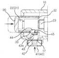
도 1은 본 발명인 휴대용 가스 토치의 구성을 도시한 단면도.
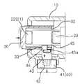
도 2는 본 발명인 안전수단을 통해 푸쉬레버의 작동이 제한된 구성을 도시한 단면도.
도 3은 본 발명인 가스 토치 구성에서 안전수단이 적용된 푸쉬레버와 안전버튼의 구성을 도시한 분해 사시도.
도 4 (a) ~ (c)는 안전버튼을 통한 푸쉬레버의 작동제어 상태를 도시한 측단면도.1 is a cross-sectional view showing the configuration of the present invention portable gas torch.
Figure 2 is a cross-sectional view showing a configuration in which the operation of the push lever is limited through the inventors safety means.
Figure 3 is an exploded perspective view showing the configuration of the push lever and the safety button is applied safety means in the present gas torch configuration.
Figure 4 (a) ~ (c) is a side cross-sectional view showing the operation control state of the push lever through the safety button.
이하, 첨부된 도면과 관련하여 상기 목적을 달성하기 위한 본 발명의 구성과 작동 예를 살펴보면 다음과 같다.DETAILED DESCRIPTION OF THE PREFERRED EMBODIMENTS Hereinafter, exemplary embodiments of the present invention will be described in detail with reference to the accompanying drawings.
본 발명인 휴대용 가스 토치는, 토치의 최초 점화를 위해 푸쉬레버를 누른 상태에서, 안전버튼을 눌러 상기 푸쉬레버를 고정시켜 지속적으로 가스를 공급할 수 있도록 하며, 다시 푸쉬레버를 누르면 안전버튼이 잠금 해제되면서 푸쉬레버가 초기위치로 복귀되어 가스 공급을 차단하도록 구성함으로써, 사용의 편의성과 안전성을 향상시킬 수 있도록 발명된 것이다.The inventors of the present invention portable gas torch, while pressing the push lever for the first ignition of the torch, by pressing the safety button to secure the push lever to continuously supply the gas, press the push lever again while the safety button is unlocked By the push lever is configured to return to the initial position to block the gas supply, it is invented to improve the ease of use and safety.
도 1 내지 도 4에 도시한 바와 같이, 본 발명인 가스 토치(60)는 크게 한쌍으로 구성된 본체부(10)의 케이스에, 밸브몸체(20)와, 푸쉬레버(30) 및 안전수단(40)이 연계된 구성으로 형성되어, 푸쉬레버(30)의 작동을 단계별로 제어하면서 작동 편의성 및 안전성을 향상시킬 수 있도록 구성된 것이다.As shown in Figs. 1 to 4, the
상기 구성에서 본체부(10)는 파지가 용이한 건 형상의 케이스 한 쌍을 상호 결합 구성한 것으로, 몸체 내부 전방으로는 노즐(11)이 구비된 기화기(12)가 형성되고, 몸체 후방의 파지부에는 그 하단에서 아답터(13)와 결속된 가스용기(70)를 통해 가스 공급을 제어하는 조절밸브(14)가 구비된다.In the above configuration, the
또한, 상기 본체부(10)의 파지부에는, 후술되는 푸쉬레버(30)가 설치될 수 있도록, 레버설치홀(16)이 전방을 향해 형성되고, 푸쉬레버(30)가 레버설치홀(16)에 슬라이드 이동가능하게 설치되어, 사용자 조작에 의해 스핀들(23) 및 점화수단(21)을 동시에 가압 작동시킬 수 있는 것이다.In addition, the holding portion of the
이때, 상기 레버설치홀(16)의 내부와, 푸쉬레버(30)의 몸체 상,하부에는 푸쉬레버(30)의 슬라이드 이동을 가이드할 수 있도록 가이드홈(31a,16a) 및 가이드레일(31b,16b)이 상호 대응되게 형성하여, 푸쉬레버(30)가 정확한 동작으로 슬라이드 이동될 수 있게 한다.At this time, the guide grooves (31a, 16a) and the guide rail (31b) to guide the slide movement of the push lever (30) on the inside of the lever installation hole (16), the upper and lower body of the push lever (30), 16b) are formed to correspond to each other, so that the
즉, 상기 푸쉬레버(30)의 상부에 형성된 가이드홈(31a)은 레버설치홀(16) 상단의 가이드레일(16b)에 끼워지고, 푸쉬레버(30) 하부에서 후방으로 돌출 성형된 가이드레일(31b)은 레버설치홀(16) 하단의 가이드홈(16a)에 상호 끼워져, 레버설치홀(16)에 결합된 푸쉬레버(30)의 슬라이드 이동시 가이드 하는 역할을 수행한다.That is, the
또, 상기 본체부(10)의 파지부에는, 몸체 내측에서 아답터(13) 상부에 위치되며, 몸체 일측으로는 점화수단(21)과 가스공급을 위한 스핀들(23)이 구비된 밸브몸체(20)가 결합된다.In addition, the gripping portion of the
상기 밸브몸체(20)는 도 1에서 도시한 바와 같이 본체부(10)의 파지부에서 수직상태로 구성되면서 노즐(11)을 구비한 기화기(12)와는 가스공급관(15)을 통해 연결되는 구성이다.The
그리고, 상기 본체부(10)의 외측에서 조절밸브(14)가 밸브몸체(20)에 결합되어, 상기 조절밸브(14)의 조작으로 가스공급관(15)으로 공급되는 가스량을 조절할 수 있도록 하였다.Then, the
즉, 상기 조절밸브(14)의 회전시켜 밸브몸체(20)와 가스공급관(15)이 개방된 상태에서, 푸쉬레버(30)를 눌러 후방 가압면(32)이 스핀들(23)을 내측으로 가압해 밸브몸체(20)내에 차단된 가스를 가스공급관으로 공급되도록 한다.That is, in the state in which the
이때, 상기 본체부(10)의 점화수단(21)인 압전소자(22)도 푸쉬레버(30)의 내측을 향한 슬라이드 이동시 동시에 눌려져 가스공급관(15)과 노즐(11)을 통해 분출되는 가스를 점화시키도록 구성된다.At this time, the
즉, 푸쉬레버(30)가 본체부(10) 내측을 향해 슬라이드 이동 시에, 몸체 후방의 가압면(32)이 밸브몸체(20)에서 돌출된 스핀들(23)과 점화수단(21)인 압전소자(22)를 가압시켜, 가스공급과 동시에 점화가 이루어질 수 있도록 하며, 푸쉬레버(30)에 대한 압력이 해소된 상태에서는, 스핀들(23)과 압전소자(22)의 복원력으로 푸쉬레버(30)가 초기위치로 슬라이드 이동될 수 있는 것이다.That is, when the
이때, 상기 푸쉬레버(30)의 가압면(32)과 스핀들(23)사이에는, 푸쉬레버(30)의 복귀를 원할히 할 수 있도록 스프링이 더 설치될 수도 있다.At this time, between the
한편, 상기 본체부(10)의 레버설치홀(16) 측면에는, 레버설치홀(16)을 따라 슬라이드 이동하면서 내부 점화수단(21) 및 압전소자(22)를 동작시키는 푸쉬레버(30)의 이동을 단속하는 안전수단(40)이 형성된다.On the other hand, on the side of the
상기 안전수단(40)은, 본체부(10)의 레버설치홀(16) 측면에 형성된 결합홀(17)에, 안전버튼(41)을 조립시켜 탄력 이동되도록, 스프링(42)이 안전버튼(41)의 몸체 내부로 삽입된 상태에서 안전버튼(41)의 삽입부(43) 일단에 형성된 걸림턱(43a)이 결합홀(17) 내측에서 걸려져 결합되는 구성을 갖게 한다.The safety means 40, the
또, 상기 안전버튼(41)의 삽입부(43)에는 잠금핀(44)이 더 연장 성형되고, 푸쉬레버(30)의 몸체 측면에도, 상기 잠금핀(44)이 삽입되도록 잠금홀(33)이 대응되게 형성되어 진다.In addition, the locking
이와 같은 상기 안전수단(40)의 구성은, 도 3에서 도시한 바와 같이 레버설치홀(16)의 케이스의 측면으로 결합홀(17)이 하나 이상 구비되도록 하고, 이에 대응되도록 안전버튼(41)의 삽입부(43)에 걸림턱(43a)이 형성되도록 한다.Such a configuration of the safety means 40, as shown in Figure 3, so that at least one
상기 안전버튼(41)은, 몸체 내부로 스프링(42)이 내장될 수 있도록 폐공간을 갖도록 하며, 다른 일단은 탄력을 갖는 삽입부(43)와 그 끝단에서 외측으로 돌출된 걸림턱(43a)이 구비된다.The
따라서, 안전버튼(41)의 몸체 내부로 스프링(42)을 내장된 상태에서 걸림턱(43a)을 결합홀(17)에 끼우면 걸림턱(43a)이 오므려지면서, 결합 후에는 결합홀(17) 내부에서 걸림턱(43a)이 탄력으로 펼쳐지면서 조립되어 안전버튼(41)이 레버설치홀(16)의 측면에 고정 결합된다.Therefore, when the locking
그리고, 안전버튼(41)의 삽입부(43)에는 걸림턱(43a)을 지나 내측을 향해 더 연장된 잠금핀(44)이 성형되며, 푸쉬레버(30)의 측면에도 상기 잠금핀(44)에 대응하는 잠금홀(33)이 형성되도록 한다.In addition, the locking
이때, 상기 잠금핀(44)의 끝단으로, 몸체 후방을 향해 돌출된 단속턱(45)을 더 성형하여, 푸쉬레버(30)의 잠금홀(33)내벽에 상기 단속턱(45)이 걸려지도록 하는 것이 중요하다.At this time, as the end of the locking
이와 같이 구성된 본 발명의 안전수단(40)을 이용한 동작 상태를 도 4a 내지 도 4c를 참고하여 설명하면, 우선 가스용기(70)를 어댑터(13)에 장착한 상태에서 조절밸브(14)를 열고 푸쉬레버(30)를 내측으로 가압해 슬라이드 이동시키게 된다.Referring to Figure 4a to 4c the operating state using the safety means 40 of the present invention configured as described above, first open the
이때, 푸쉬레버(30)의 이동에 따라 밸브몸체(20)의 스핀들(23)과 점화수단(21)인 압전소자(22)를 가압하게 되고, 가스용기(70)의 부탄가스는 밸브몸체(20)에서 노즐(11)까지 개방된 상태이므로 전방으로 분출되면서 압전소자(22)의 불꽃에 점화가 이루어진다.At this time, as the
이후, 작업자가 장시간 가스 토치를 사용할 경우에는 안전버튼(41)을 도 4b에서 도시한 바와 같이 도면상 내부를 향해 눌러주면 안전버튼(41)의 내부끝단에 형성된 잠금핀(44)이 레버설치홀(16) 내부에서 후방으로 슬라이드 이동된 푸쉬레버(30)의 잠금홀(33)에 삽입된다.Subsequently, when the operator uses the gas torch for a long time, as shown in FIG. 4B, when the
이때, 푸쉬레버(30)의 잠금홀(33)에 삽입된 잠금핀(44)은 푸쉬레버(30)에 대한 가압력 해제 시에 스핀들(23)과 압전소자(22)의 복원력으로 푸쉬레버(30)가 전방으로 이동되는 과정에서 잠금홀(33)의 내면과 맞물려 상호 움직임이 제한되어진다.At this time, the locking
따라서, 상기 안전버튼(41)의 잠금핀(44)이 푸쉬레버(30)의 잠금홀(33)에 끼워져 있는 상태에서는 푸쉬레버(30)에 대한 가압력을 해제하여도 푸쉬레버(30)가 전방으로 슬라이드 이동되는 것을 제한하게 된다.Therefore, in the state that the locking
특히, 상기 안전버튼(41)의 잠금핀(44)에 더 성형된 단속턱(45)이 푸쉬레버(30)의 잠금홀(33)내벽에 걸려지도록 하여 충격이나 미끄러짐에 따라 임의로 안전버튼(41)이 해제되는 것을 방지하여 안전사고 및 편의성을 증대시킬 수 있게 하는 것이 중요하다.In particular, the
따라서, 도 4b와 같이 상기 푸쉬레버(30)가 내측으로 이동된 상태가 유지되어, 스핀들(23)을 가압하면서 가스공급을 지속적으로 진행하게 되어 사용자는 파지부를 잡고 작업을 수행할 수 있게 된다.Therefore, as shown in FIG. 4B, the
또한, 가스 토치(60)의 사용을 중단할 시에는 도 4c에서 도시한 바와 같이 푸쉬레버(30)를 내측으로 가압하면, 잠금홀(33)에 걸려져 움직임을 제한받던 단속턱(45)이 안전버튼(41)의 스프링(42) 탄력으로 원위치 복원되면서 푸쉬레버(30)에 대한 잠김을 해제한다.In addition, when the use of the
따라서, 레버설치홀(16)내에 위치된 푸쉬레버(30)가, 스핀들(23) 및 압전소자(22)의 복귀되는 힘으로 전방을 향해 슬라이드 이동되면서, 가스 토치(60)의 최초 상태로 복귀되는 것이다.Accordingly, the
이와 같이, 본 발명의 구성은 작업자 이외에 비사용자나 여성 등의 오동작으로 인한 안전사고를 미연에 방지하면서, 한 손을 사용해 작동시킬 수 있도록 하여 편의성을 향상시킬 수 있도록 한 것이다.In this way, the configuration of the present invention is to improve the convenience by allowing one hand to operate while preventing safety accidents caused by malfunctions of non-users or women other than the operator.
이상에서 설명한 본 발명은 전술한 실시 예 및 도면에 의해 한정되는 것은 아니며, 본 발명의 기술적 사상을 벗어나지 않는 범위 내에서 여러 가지 치환, 변형 및 변경이 가능함은 본 발명이 속하는 기술 분야에서 통상의 지식을 가진 자에게 있어 명백할 것이다.
It will be apparent to those skilled in the art that various modifications and variations can be made in the present invention without departing from the spirit or scope of the invention. It will be clear to those who have.
10 - 본체부11 - 노즐
12 - 기화기13 - 아답터
14 - 조절밸브15 - 가스공급관
16 - 레버설치홀17 - 결합홀
20 - 밸브몸체21 - 점화수단
22 - 압전소자23 - 스핀들
30 - 푸쉬레버32 - 가압면
33 - 잠금홀40 - 안전수단
41 - 안전버튼42 - 스프링
43 - 삽입부44 - 잠금핀
45 - 단속턱60 - 가스 토치
70 - 가스용기10-Body 11-Nozzle
12-Carburetor 13-Adapter
14-regulating valve 15-gas supply line
16-lever mounting hole 17-coupling hole
20-valve body 21-ignition means
22-Piezoelectric element 23-Spindle
30-push lever 32-pressing surface
33-Lock Hole 40-Safety Measures
41-Safety Button 42-Spring
43-Insert 44-Locking Pin
45-Intermittent Jaw 60-Gas Torch
70-gas container
Claims (4)
Translated fromKorean상기 본체부(10)의 후방 내측에서 아답터(13) 상부로 위치되며, 몸체 일측으로 점화수단(21)과 가스공급을 위한 스핀들(23)이 레버설치홀(16)을 향해 형성되는 밸브몸체(20)와;
상기 본체부(10)의 레버설치홀(16)에 결합되어 내측으로 슬라이드 이동하며, 후방 이동 시 스핀들(23)과 점화수단(21)을 가압시킬 수 있도록 형성되는 푸쉬레버(30)와,
상기 본체부(10) 내부에서 점화수단(21) 및 푸쉬레버(30)의 작동을 단계적으로 제어할 수 있는 안전수단(40)으로 구성된 것에 있어서;
상기 안전수단(40)은, 본체부(10)의 레버설치홀(16) 측면으로 결합홀(17)을 형성시켜, 몸체 내부로 스프링(42)이 구비된 안전버튼(41)의 삽입부(43)를 상기 결합홀(17)에 끼워 안전버튼(41)이 탄력 이동되도록 결합하며, 상기 레버설치홀(16) 내부로 끼워진 삽입부(43)에 더 연장 성형된 잠금핀(44)에 대응되도록 푸쉬레버(30)의 몸체 측면에 잠금홀(33)을 형성시켜 구성되는 것을 특징으로 한 휴대용 가스 토치.
A vaporizer 12 having a nozzle 11 is formed at the front of the body, and a control valve 14 is provided at the rear of the body to control the gas supply through the gas container 70 which is coupled to the adapter 13 at the bottom. A main body portion 10 in which a lever mounting hole 16 is formed in front;
The valve body which is located above the adapter 13 in the rear inner side of the main body 10, the ignition means 21 and the spindle 23 for gas supply toward one side of the body toward the lever installation hole 16 ( 20);
A push lever 30 coupled to the lever installation hole 16 of the main body 10 to slide inward and to pressurize the spindle 23 and the ignition means 21 during the rearward movement;
In the main body (10) in the configuration consisting of safety means (40) for controlling the operation of the ignition means (21) and the push lever (30) step by step;
The safety means 40, by forming a coupling hole 17 in the side of the lever mounting hole 16 of the main body portion 10, the insertion portion of the safety button 41 is provided with a spring 42 into the body ( 43 is inserted into the coupling hole 17 so that the safety button 41 is elastically moved, and corresponds to the locking pin 44 further extended to the insertion portion 43 inserted into the lever installation hole 16. Portable gas torch, characterized in that configured to form a locking hole 33 in the body side of the push lever (30).
The portable gas torch according to claim 1, wherein the locking pin (44) of the safety button (41) is further extended inward and is formed with an intermittent jaw (45) bent toward the rear of the body.
The locking pin 44 according to any one of claims 1 to 4, wherein the locking state of the push lever 30 is configured by pressing the safety button 41 while pressing the push lever 30 to move inward. After allowing the push lever 30 to be inserted into the locking hole 33, the pressing force against the push lever 30 is released, and the push lever 30 is restored by the restoring force of the spindle 23 and the ignition means 21 at the rear of the body. Portable gas torch, characterized in that the locking hole (33) the inner surface of the locking jaw (45) formed on the end of the locking pin (44) to limit the movement of the push lever 30 is moved forward.
Priority Applications (1)
| Application Number | Priority Date | Filing Date | Title |
|---|---|---|---|
| KR1020110107114AKR101289701B1 (en) | 2011-10-19 | 2011-10-19 | Portable gas torch |
Applications Claiming Priority (1)
| Application Number | Priority Date | Filing Date | Title |
|---|---|---|---|
| KR1020110107114AKR101289701B1 (en) | 2011-10-19 | 2011-10-19 | Portable gas torch |
Publications (2)
| Publication Number | Publication Date |
|---|---|
| KR20130042943A KR20130042943A (en) | 2013-04-29 |
| KR101289701B1true KR101289701B1 (en) | 2013-07-26 |
Family
ID=48441403
Family Applications (1)
| Application Number | Title | Priority Date | Filing Date |
|---|---|---|---|
| KR1020110107114ACeasedKR101289701B1 (en) | 2011-10-19 | 2011-10-19 | Portable gas torch |
Country Status (1)
| Country | Link |
|---|---|
| KR (1) | KR101289701B1 (en) |
Cited By (3)
| Publication number | Priority date | Publication date | Assignee | Title |
|---|---|---|---|---|
| KR200486230Y1 (en) | 2017-06-05 | 2018-04-19 | 강준상 | Potable Gas Torch |
| KR102685002B1 (en) | 2024-06-25 | 2024-07-15 | (주)니드코 | Potable Gas Torch |
| KR102856132B1 (en)* | 2025-02-28 | 2025-09-04 | 김주학 | Gun-type gas supply torch with a two-way valve body structure |
Families Citing this family (4)
| Publication number | Priority date | Publication date | Assignee | Title |
|---|---|---|---|---|
| RU2693558C1 (en)* | 2018-10-16 | 2019-07-03 | Алексей Владимирович Вытовтов | Device for simulating flare combustion at break of gas line |
| CN112128762B (en)* | 2020-10-26 | 2025-03-04 | 郑甜甜 | Flamethrower |
| KR102552950B1 (en) | 2021-06-11 | 2023-07-10 | 주식회사 썬터치 | Gas preheating system and gas torch lamp with this |
| KR102371686B1 (en)* | 2021-08-13 | 2022-03-08 | (주)제이디아웃도어 | Torch for searing |
Citations (4)
| Publication number | Priority date | Publication date | Assignee | Title |
|---|---|---|---|---|
| JP3139878U (en) | 2007-12-18 | 2008-03-06 | ライオン株式会社 | Aerosol device |
| KR200440429Y1 (en) | 2007-03-28 | 2008-06-12 | 주식회사 코베아 | Torch lamp |
| KR20100120562A (en)* | 2009-05-06 | 2010-11-16 | 주식회사 동주웰딩 | Torch handle including torch safety means for use in hand-operated welding torch |
| KR20120002460U (en)* | 2010-09-30 | 2012-04-09 | 현대중공업 주식회사 | Gas torch with safety valve |
- 2011
- 2011-10-19KRKR1020110107114Apatent/KR101289701B1/ennot_activeCeased
Patent Citations (4)
| Publication number | Priority date | Publication date | Assignee | Title |
|---|---|---|---|---|
| KR200440429Y1 (en) | 2007-03-28 | 2008-06-12 | 주식회사 코베아 | Torch lamp |
| JP3139878U (en) | 2007-12-18 | 2008-03-06 | ライオン株式会社 | Aerosol device |
| KR20100120562A (en)* | 2009-05-06 | 2010-11-16 | 주식회사 동주웰딩 | Torch handle including torch safety means for use in hand-operated welding torch |
| KR20120002460U (en)* | 2010-09-30 | 2012-04-09 | 현대중공업 주식회사 | Gas torch with safety valve |
Cited By (3)
| Publication number | Priority date | Publication date | Assignee | Title |
|---|---|---|---|---|
| KR200486230Y1 (en) | 2017-06-05 | 2018-04-19 | 강준상 | Potable Gas Torch |
| KR102685002B1 (en) | 2024-06-25 | 2024-07-15 | (주)니드코 | Potable Gas Torch |
| KR102856132B1 (en)* | 2025-02-28 | 2025-09-04 | 김주학 | Gun-type gas supply torch with a two-way valve body structure |
Also Published As
| Publication number | Publication date |
|---|---|
| KR20130042943A (en) | 2013-04-29 |
Similar Documents
| Publication | Publication Date | Title |
|---|---|---|
| KR101289701B1 (en) | Portable gas torch | |
| US6648630B2 (en) | Gas igniter with flexible extension | |
| US7708554B2 (en) | Safety structure of a gas burner | |
| US9784446B2 (en) | Gas combustor having detachable combustion device | |
| US11448397B2 (en) | Gas combustor and safety switch thereof | |
| US7001175B2 (en) | Utility lighter with safety arrangement | |
| US20030203331A1 (en) | Safety mechanism for a torch | |
| JP3033033B2 (en) | Gas lighter with safety device | |
| US6296476B1 (en) | Gas burner safety control mechanism | |
| KR200440429Y1 (en) | Torch lamp | |
| US10302303B2 (en) | Cigarette lighter for safely moving through dangerous areas and method of use | |
| US6840759B2 (en) | Igniter incorporating a safety locking device | |
| US6447287B1 (en) | Safety gas lighter | |
| TWM543962U (en) | Gas burner and safety button thereof | |
| KR200486230Y1 (en) | Potable Gas Torch | |
| US20090104574A1 (en) | Utility Lighter | |
| JP3663288B2 (en) | Igniter | |
| US20040191715A1 (en) | Ignitor | |
| TWM605270U (en) | Safety switch for gas burner | |
| US20040131985A1 (en) | Ignitor | |
| JP3169595U (en) | Igniter | |
| CN202188526U (en) | Lighter | |
| CA2995692A1 (en) | Cigarette lighter for safely moving through dangerous areas and method of use | |
| US20040121276A1 (en) | Lighter | |
| KR101404470B1 (en) | Gas torch |
Legal Events
| Date | Code | Title | Description |
|---|---|---|---|
| A201 | Request for examination | ||
| PA0109 | Patent application | Patent event code:PA01091R01D Comment text:Patent Application Patent event date:20111019 | |
| PA0201 | Request for examination | ||
| E902 | Notification of reason for refusal | ||
| PE0902 | Notice of grounds for rejection | Comment text:Notification of reason for refusal Patent event date:20130201 Patent event code:PE09021S01D | |
| PG1501 | Laying open of application | ||
| E701 | Decision to grant or registration of patent right | ||
| PE0701 | Decision of registration | Patent event code:PE07011S01D Comment text:Decision to Grant Registration Patent event date:20130625 | |
| GRNT | Written decision to grant | ||
| PR0701 | Registration of establishment | Comment text:Registration of Establishment Patent event date:20130719 Patent event code:PR07011E01D | |
| PR1002 | Payment of registration fee | Payment date:20130722 End annual number:3 Start annual number:1 | |
| PG1601 | Publication of registration | ||
| PJ0204 | Invalidation trial for patent | Patent event date:20140318 Comment text:Request for Trial Patent event code:PJ02042R01D Patent event date:20130719 Comment text:Registration of Establishment Patent event code:PJ02041E01I Appeal kind category:Invalidation Request date:20140318 Decision date:20141219 Appeal identifier:2014100000680 | |
| J301 | Trial decision | Free format text:TRIAL DECISION FOR INVALIDATION REQUESTED 20140318 Effective date:20141219 | |
| PJ1301 | Trial decision | Patent event code:PJ13011S05D Patent event date:20141222 Comment text:Trial Decision on Invalidation (Patent, Utility Model, Industrial Design) Appeal kind category:Invalidation Request date:20140318 Decision date:20141219 Appeal identifier:2014100000680 | |
| J2X1 | Appeal (before the patent court) | Free format text:INVALIDATION | |
| PJ2001 | Appeal | Patent event date:20141222 Comment text:Trial Decision on Invalidation (Patent, Utility Model, Industrial Design) Patent event code:PJ20011S05I Appeal kind category:Invalidation Decision date:20150821 Appeal identifier:2015200000482 Request date:20150121 | |
| J302 | Written judgement (patent court) | Free format text:JUDGMENT (PATENT COURT) FOR INVALIDATION REQUESTED 20150121 Effective date:20150821 | |
| PJ1302 | Judgment (patent court) | Patent event date:20150918 Comment text:Written Judgment (Patent Court) Patent event code:PJ13021S01D Request date:20150121 Decision date:20150821 Appeal identifier:2015200000482 Appeal kind category:Invalidation | |
| PG1701 | Publication of correction | Publication date:20150930 | |
| J206 | Request for trial to confirm the scope of a patent right | ||
| PJ0206 | Trial to confirm the scope of a patent | Patent event code:PJ02062R01D Patent event date:20151221 Comment text:Request for Trial Patent event code:PJ02061E01I Patent event date:20130719 Comment text:Registration of Establishment Decision date:20161118 Request date:20151221 Appeal identifier:2015100005676 Appeal kind category:Confirmation of the scope of right_defensive | |
| J204 | Request for invalidation trial [patent] | ||
| PJ0204 | Invalidation trial for patent | Patent event date:20160106 Comment text:Request for Trial Patent event code:PJ02042R01D Patent event date:20130719 Comment text:Registration of Establishment Patent event code:PJ02041E01I Appeal kind category:Invalidation Request date:20160106 Decision date:20161118 Appeal identifier:2016100000040 | |
| FPAY | Annual fee payment | Payment date:20160616 Year of fee payment:4 | |
| PR1001 | Payment of annual fee | Payment date:20160616 Start annual number:4 End annual number:4 | |
| J301 | Trial decision | Free format text:TRIAL NUMBER: 2016100000040; TRIAL DECISION FOR INVALIDATION REQUESTED 20160106 Effective date:20161118 Free format text:TRIAL NUMBER: 2015100005676; TRIAL DECISION FOR CONFIRMATION OF THE SCOPE OF RIGHT_DEFENSIVE REQUESTED 20151221 Effective date:20161118 | |
| PJ1301 | Trial decision | Appeal kind category:Invalidation Request date:20160106 Decision date:20161118 Appeal identifier:2016100000040 Patent event code:PJ13011S05D Patent event date:20161118 Comment text:Trial Decision on Invalidation (Patent, Utility Model, Industrial Design) Patent event code:PJ13011S02D Patent event date:20161118 Comment text:Trial Decision for Confirmation of the Scope of a Right (Patent, Utility Model, Industrial Design) Appeal kind category:Confirmation of the scope of right_defensive Request date:20151221 Decision date:20161118 Appeal identifier:2015100005676 | |
| J2X1 | Appeal (before the patent court) | Free format text:TRIAL NUMBER: 2016200009325; INVALIDATION | |
| PJ2001 | Appeal | Patent event date:20161118 Comment text:Trial Decision on Invalidation (Patent, Utility Model, Industrial Design) Patent event code:PJ20011S05I Patent event date:20161118 Comment text:Trial Decision for Confirmation of the Scope of a Right (Patent, Utility Model, Industrial Design) Patent event code:PJ20011S02I Patent event date:20141222 Comment text:Trial Decision on Invalidation (Patent, Utility Model, Industrial Design) Patent event code:PJ20011S05I Appeal kind category:Invalidation Decision date:20180524 Appeal identifier:2016200009325 Request date:20161216 | |
| PR1001 | Payment of annual fee | Payment date:20170531 Start annual number:5 End annual number:5 | |
| J302 | Written judgement (patent court) | Free format text:TRIAL NUMBER: 2016200009325; JUDGMENT (PATENT COURT) FOR INVALIDATION REQUESTED 20161216 Effective date:20180524 | |
| PJ1302 | Judgment (patent court) | Patent event date:20180629 Comment text:Written Judgment (Patent Court) Patent event code:PJ13021S01D Request date:20161216 Decision date:20180524 Appeal identifier:2016200009325 Appeal kind category:Invalidation | |
| PJ2201 | Remand (intellectual property tribunal) | Patent event code:PJ22012S01I Comment text:Written Judgment (Patent Court) Patent event date:20180629 Request date:20180629 Appeal kind category:Invalidation Appeal identifier:2018130000087 Decision date:20180730 | |
| FPAY | Annual fee payment | Payment date:20180702 Year of fee payment:6 | |
| PR1001 | Payment of annual fee | Payment date:20180702 Start annual number:6 End annual number:6 | |
| J301 | Trial decision | Free format text:TRIAL NUMBER: 2018130000087; TRIAL DECISION FOR INVALIDATION REQUESTED 20180629 Effective date:20180730 | |
| PJ1301 | Trial decision | Patent event code:PJ13011S09D Patent event date:20180730 Comment text:Trial Decision on Final Judgment on Revocation Appeal kind category:Invalidation Request date:20180629 Decision date:20180730 Appeal identifier:2018130000087 | |
| PC2102 | Extinguishment | Termination category:Others Termination date:20181024 |