KR101288241B1 - Water dispenser for drip coffee - Google Patents
Water dispenser for drip coffeeDownload PDFInfo
- Publication number
- KR101288241B1 KR101288241B1KR1020110087640AKR20110087640AKR101288241B1KR 101288241 B1KR101288241 B1KR 101288241B1KR 1020110087640 AKR1020110087640 AKR 1020110087640AKR 20110087640 AKR20110087640 AKR 20110087640AKR 101288241 B1KR101288241 B1KR 101288241B1
- Authority
- KR
- South Korea
- Prior art keywords
- water
- coffee
- drip coffee
- main body
- present
- Prior art date
- Legal status (The legal status is an assumption and is not a legal conclusion. Google has not performed a legal analysis and makes no representation as to the accuracy of the status listed.)
- Expired - Fee Related
Links
Images

Classifications
- A—HUMAN NECESSITIES
- A47—FURNITURE; DOMESTIC ARTICLES OR APPLIANCES; COFFEE MILLS; SPICE MILLS; SUCTION CLEANERS IN GENERAL
- A47J—KITCHEN EQUIPMENT; COFFEE MILLS; SPICE MILLS; APPARATUS FOR MAKING BEVERAGES
- A47J31/00—Apparatus for making beverages
- A47J31/02—Coffee-making machines with removable extraction cups, to be placed on top of drinking-vessels i.e. coffee-makers with removable brewing vessels, to be placed on top of beverage containers, into which hot water is poured, e.g. cafe filter
- A—HUMAN NECESSITIES
- A47—FURNITURE; DOMESTIC ARTICLES OR APPLIANCES; COFFEE MILLS; SPICE MILLS; SUCTION CLEANERS IN GENERAL
- A47J—KITCHEN EQUIPMENT; COFFEE MILLS; SPICE MILLS; APPARATUS FOR MAKING BEVERAGES
- A47J31/00—Apparatus for making beverages
- A47J31/06—Filters or strainers for coffee or tea makers ; Holders therefor
- A—HUMAN NECESSITIES
- A47—FURNITURE; DOMESTIC ARTICLES OR APPLIANCES; COFFEE MILLS; SPICE MILLS; SUCTION CLEANERS IN GENERAL
- A47J—KITCHEN EQUIPMENT; COFFEE MILLS; SPICE MILLS; APPARATUS FOR MAKING BEVERAGES
- A47J31/00—Apparatus for making beverages
- A47J31/44—Parts or details or accessories of beverage-making apparatus
- A47J31/46—Dispensing spouts, pumps, drain valves or like liquid transporting devices
Landscapes
- Engineering & Computer Science (AREA)
- Food Science & Technology (AREA)
- Apparatus For Making Beverages (AREA)
Abstract
Translated fromKoreanDescription
Translated fromKorean본 발명은 물 공급기에 관한 것으로서, 더욱 상세하게는 물이 천천히 골고루 커피 가루에 공급되도록 하여 전문가가 아니더라도 간편하게 향미가 우수한 드립 커피를 즐길 수 있는 드립 커피용 물 공급기에 관한 것이다.The present invention relates to a water feeder, and more particularly, to a water feeder for drip coffee that allows water to be slowly and evenly supplied to the coffee powder so that the drip coffee can easily enjoy excellent flavor even if not an expert.
일반적으로 드립(Drip)이란 커피를 끓이는 방법의 하나로 커피를 잘게 빻은 원두에 끓는 물을 부어 걸러 내는 것이며, 드립 커피(Drip Coffee)란 드립식 커피 끓이는 도구(특허 제1018497호 참조)로 만든 커피를 말한다.In general, drip is a method of brewing coffee by filtering boiling coffee with finely ground coffee and boiling water. Say.
그리고, 드립 커피는 먼저 분쇄된 커피 가루를 종이 필터에 담아 깔때기 모양의 드립퍼에 올려놓고, 주전자를 손으로 잡아서 물을 드립퍼의 중앙으로부터 원을 그리며 안팎으로 양을 조절해가며 붓는다.Then, the drip coffee is first put the crushed coffee powder in a paper filter and placed in a funnel-shaped dripper, and hold the kettle by hand and pour water in a circle from the center of the dripper to adjust the amount inside and out.
그런데, 이러한 드립 방식은 물을 붓는 사람에 따라 커피의 맛과 향이 다르게 되고, 바리스타와 같은 숙련자가 아닌 경우 드립퍼에 물을 적절히 균일하게 공급하지 못하여 좋은 커피맛을 내기 어려운 문제점이 있다.By the way, the drip method is different from the taste and aroma of the coffee according to the pouring water, there is a problem that it is difficult to produce a good coffee taste because it does not properly supply water to the dripper even if the skilled person such as a barista.
본 발명은 상기와 같은 종래 기술의 문제점을 해결하기 위하여 안출된 것으로서, 바리스타와 같은 숙련자가 아니더라고 드립퍼에 물을 천천히 균일하게 공급할 수 있어서 커피의 맛과 향을 최적의 상태로 음미할 수 있는 드립 커피용 물 공급기를 제공하는데 그 목적이 있다.The present invention has been made to solve the problems of the prior art as described above, drip can be supplied to the dripper evenly, even if you are not skilled in the barista to enjoy the taste and aroma of coffee in an optimal state The object is to provide a coffee water supply.
이와 같은 목적을 달성하기 위한 본 발명의 드립 커피용 물 공급기는 물이 수용되는 컵 형태로, 바닥에 방사상으로 천공된 홀을 따라 하부로 연장된 복수 개의 유도관이 구비되는 본체; 상기 본체 유도관과의 사이에 물이 이동하는 미세 공간을 형성하도록 복수 개의 유도관과 각각 하나씩 대응하도록 삽입되는 복수 개의 수직 결합봉이 구비되는 보조체를 포함하여 구성되는 것을 특징으로 한다.Drip coffee water supply of the present invention for achieving the above object is a cup-shaped receiving water, the body is provided with a plurality of induction pipes extending downward along the radially perforated hole in the bottom; And an auxiliary body provided with a plurality of induction pipes and a plurality of vertical coupling rods inserted to correspond to each of the plurality of induction pipes so as to form a microcavity in which water moves between the body induction pipes.
여기서, 상기 본체 하부는 둘레를 따라 플랜지가 연장되고, 상기 보조체는 수직 결합봉이 방사상으로 부착되는 지지체가 구비되며, 상기 지지체 상부에는 손잡이가 돌출되는 것을 특징으로 한다.Here, the lower portion of the main body is a flange extending along the circumference, the auxiliary body is provided with a support to which the vertical coupling rod radially attached, characterized in that the handle is projected on the upper support.
이와 같이 구성된 본 발명의 드립 커피용 물 공급기는 숙련자가 아니더라고 간편하게 사용할 수 있고 물을 천천히 균일하게 공급하여 우수한 커피맛을 느낄 수 있는 유용한 효과를 발휘한다.The drip coffee water supply device of the present invention configured as described above can be conveniently used even if not skilled, and slowly and uniformly supply water to exert a useful effect of feeling an excellent coffee taste.
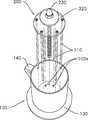
도 1은 본 발명에 따른 드립 커피용 물 공급기를 나타내는 사시도;
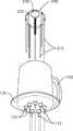
도 2는 본 발명에 따른 드립 커피용 물 공급기를 나타내는 상부 분리 사시도;
도 3은 본 발명에 따른 드립 커피용 물 공급기를 나태는 하부 분리 사시도;
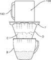
도 4는 본 발명에 따른 드립 커피용 물 공급기를 나타내는 사용 상태도이다.1 is a perspective view showing a water supply for a drip coffee according to the present invention;
Figure 2 is a perspective view of the top separation of the drip coffee water supply according to the present invention;
3 is a bottom separated perspective view of the drip coffee water supply unit according to the present invention;
Figure 4 is a use state diagram showing the drip coffee water supply according to the present invention.
이하, 본 발명의 목적이 구체적으로 실현될 수 있는 바람직한 실시예를 첨부된 도면을 참조하여 상세히 설명한다. 본 실시예를 설명함에 있어서, 동일 구성에 대해서는 동일 명칭 및 동일 부호가 사용되며 이에 따른 부가적인 설명은 생략하기로 한다.DETAILED DESCRIPTION OF THE PREFERRED EMBODIMENTS Hereinafter, preferred embodiments of the present invention will be described in detail with reference to the accompanying drawings. In describing the present embodiment, the same designations and the same reference numerals are used for the same components, and further description thereof will be omitted.
도 1은 본 발명에 따른 드립 커피용 물 공급기를 나타내는 사시도이고, 도 2는 본 발명에 따른 드립 커피용 물 공급기를 나타내는 상부 분리 사시도이며, 도 3은 본 발명에 따른 드립 커피용 물 공급기를 나태는 하부 분리 사시도이고, 도 4는 본 발명에 따른 드립 커피용 물 공급기를 나타내는 사용 상태도이다.1 is a perspective view showing a water supply for a drip coffee according to the present invention, Figure 2 is a top separated perspective view showing a water supply for a drip coffee according to the present invention, Figure 3 is a slotted drip coffee water supply according to the
본 발명의 드립 커피용 물 공급기는 도 1 내지 도 4 도시된 바와 같이, 본체(100)와 보조체(200)를 포함하여 구성된다.As shown in FIGS. 1 to 4, the drip coffee water supply of the present invention includes a
본체(100)는 드립퍼(D)에 공급될 물이 수용되는 내부공간이 형성된 컵 형태로 바닥에 중앙을 기준하여 방사상으로 홀(100a)이 천공되고, 상기 홀(100a)을 따라 복수 개의 유도관(110)이 하부로 연장된다.The
도면에서는 본 발명이 일 실시예로 상기 방사상의 홀(100a)과 복수 개의 유도관(110)을 7개로 도시하였으나, 드립퍼의 용량이나 홀(100a)과 유도관(110)의 직경에 따라 개수를 조절할 수 있음은 물론이다.In the drawings, although the present invention shows seven
그리고, 상기 복수 개의 유도관(110)과 본체(100)는 물이 누출되지 않도록 본체(100) 하면과 유도관(110)의 사이에 패킹고무(120)가 개재되는 것이 바람직하다.In addition, the plurality of
또한, 상기 본체(100)는 손으로 잡고 드립퍼(D) 상에 설치 및 분리가 편리하도록 하부에 둘레를 따라 플랜지(130)가 연장되고, 측면에 본체 손잡이(140)가 구비되는 것이 더욱 바람직하다.In addition, the
보조체(200)는 상기 본체(100) 복수 개의 유도관(110)과의 사이에 물이 이동하는 미세 공간을 형성하도록 복수 개의 유도관(110)과 각각 하나씩 대응하도록 삽입되는 복수 개의 수직 결합봉(210)이 구비된다.The
상기 본체(100) 유도관(110)과 수직 결합봉(210) 사이의 미세 공간(틈)은 0.1~0.5mm 정도가 바람직하고, 이러한 미세 공간에 의해 본체(100) 내에 공급된 물은 수직 결합봉(210)의 하단을 따라 방울 방울 천천히 드립퍼(D)에 투하될 수 있다.The microcavity (gap) between the
더욱이, 유도관(110)과 수직 결합봉(210)이 방사상으로 형성되어 있기 때문에 실제 바리스타가 주전자를 들고 드립퍼(D)에 원을 그리며 물을 균일하게 공급하는 것과 같은 효과를 가져올 수 있다.Furthermore, since the
상기 보조체(200)는 수직 결합봉(210)이 수직으로 부착되는 원판형의 지지체(220)가 구비되며, 상기 지지체(220) 상부에는 보조체(200)를 본체(100)에 결합 내지 분리가 편리하도록 보조체 손잡이(230)가 돌출되는 것이 바람직하다.The
도면에서는 본 발명의 일 실시예로 상기 플랜지(130)와 지지체(220)를 합성수지와 같은 투명 재질로 구성하였다.In the drawings, the
본 발명의 드립 커피용 물 공급기의 사용방법을 살펴보면 도 4에 도시된 바와 같이, 먼저 커피용기(B) 상에 깔때기 형태의 드립퍼(D)를 놓고, 드립퍼(D) 내에 필터(F)를 설치한 다음, 필터(F) 내에 커피 가루(C)를 붓는다.Looking at the use of the drip coffee water supply of the present invention, as shown in Figure 4, first placed a funnel-shaped dripper (D) on the coffee container (B), the filter (F) is installed in the dripper (D) Then, the coffee powder (C) is poured into the filter (F).
그리고, 보조체(200)의 수직 결합봉(210)을 본체(100)의 유도관(110)에 삽입한 후 플랜지(130)를 이용하여 본체(100)를 드립퍼(D)의 상부에 배치시키고 본체(100) 내부에 물을 공급한다.In addition, the
다음으로, 본체(100)에 공급된 물은 본체(100)의 유도관(110)과 보조체(200)의 수직 결합봉(210) 사이의 미세 공간을 따라 흘러 방사상으로 수직 결합봉(210) 하단으로부터 방울 방울 드립퍼(D)로 천천히 균일하게 떨어지게 된다.Next, the water supplied to the
마지막으로, 드립퍼(D)로 공급된 물은 커피 가루(C)를 시간을 두고 천천히 용해시키고 완성된 커피액은 커피 용기(B)에 조금씩 저장된다.Finally, the water supplied to the dripper D slowly dissolves the coffee powder C over time and the finished coffee liquid is stored in the coffee container B little by little.
이와 같이 본 발명에 따른 바람직한 실시예를 살펴보았으며, 앞서 설명된 실시예 이외에도 본 발명이 그 취지나 범주에서 벗어남이 없이 다른 특정 형태로 구체화될 수 있다는 사실은 해당 기술분야에 있어 통상의 지식을 가진 자에게는 자명한 것이다.It will be apparent to those skilled in the art that the present invention may be embodied in other specific forms without departing from the spirit or scope of the invention as defined in the appended claims. It is self-evident to those who have.
그러므로, 상술된 실시예는 제한적인 것이 아니라 예시적인 것으로 여겨져야 하며, 이에 따라 본 발명은 상술한 설명에 한정되지 않고 첨부된 청구항의 범주 및 그 동등 범위 내에서 변경될 수 있다.Therefore, the above-described embodiments are to be considered as illustrative rather than restrictive, and the present invention is not limited to the above description, but may be modified within the scope of the appended claims and equivalents thereof.
100: 본체100a: 홀
110: 유도관120: 패킹고무
130: 플랜지140: 본체 손잡이
200: 보조체210: 수직 결합봉
220: 지지체230: 보조체 손잡이100:
110: guide tube 120: packing rubber
130: flange 140: body handle
200: auxiliary body 210: vertical coupling rod
220: support 230: auxiliary handle
Claims (2)
Translated fromKorean상기 본체 유도관과의 사이에 물이 이동하는 미세 공간을 형성하도록 복수 개의 유도관과 각각 하나씩 대응하도록 삽입되는 복수 개의 수직 결합봉이 구비되는 보조체를 포함하여 구성되는 것을 특징으로 하는 드립 커피용 물 공급기.A main body having a plurality of induction pipes extending downward along a hole radially drilled in a bottom in a cup shape receiving water;
Drip coffee water, characterized in that it comprises an auxiliary body having a plurality of vertical coupling rods are inserted to correspond to each of a plurality of induction pipes so as to form a micro-cavity to move the water between the main body induction pipes feeder.
상기 본체 하부는 둘레를 따라 플랜지가 연장되고, 상기 보조체는 수직 결합봉이 방사상으로 부착되는 지지체가 구비되며, 상기 지지체 상부에는 손잡이가 돌출되는 것을 특징으로 하는 드립 커피용 물 공급기.The method of claim 1,
The lower portion of the main body is a flange extending along the circumference, the auxiliary body is provided with a support to which the vertical coupling rod is radially attached, the upper portion of the support is drip coffee water supply, characterized in that the handle protrudes.
Priority Applications (1)
| Application Number | Priority Date | Filing Date | Title |
|---|---|---|---|
| KR1020110087640AKR101288241B1 (en) | 2011-08-31 | 2011-08-31 | Water dispenser for drip coffee |
Applications Claiming Priority (1)
| Application Number | Priority Date | Filing Date | Title |
|---|---|---|---|
| KR1020110087640AKR101288241B1 (en) | 2011-08-31 | 2011-08-31 | Water dispenser for drip coffee |
Publications (2)
| Publication Number | Publication Date |
|---|---|
| KR20130024284A KR20130024284A (en) | 2013-03-08 |
| KR101288241B1true KR101288241B1 (en) | 2013-07-26 |
Family
ID=48176379
Family Applications (1)
| Application Number | Title | Priority Date | Filing Date |
|---|---|---|---|
| KR1020110087640AExpired - Fee RelatedKR101288241B1 (en) | 2011-08-31 | 2011-08-31 | Water dispenser for drip coffee |
Country Status (1)
| Country | Link |
|---|---|
| KR (1) | KR101288241B1 (en) |
Cited By (1)
| Publication number | Priority date | Publication date | Assignee | Title |
|---|---|---|---|---|
| KR101454740B1 (en) | 2013-04-29 | 2014-10-27 | 상운 남 | Machine for drip coffee including branch pipes |
Families Citing this family (1)
| Publication number | Priority date | Publication date | Assignee | Title |
|---|---|---|---|---|
| KR200486683Y1 (en)* | 2017-07-10 | 2018-06-21 | 주식회사 로스팅 파크 커피 컴퍼니 | Drip coffee machine |
Citations (2)
| Publication number | Priority date | Publication date | Assignee | Title |
|---|---|---|---|---|
| KR19990087660A (en)* | 1996-03-12 | 1999-12-27 | 게.바우츠, 아이. 호프만 | Coffee machine and filter elements for this machine |
| KR20090075650A (en)* | 2009-06-08 | 2009-07-08 | 안승대 | Drip Coffee & Tea Maker |
- 2011
- 2011-08-31KRKR1020110087640Apatent/KR101288241B1/ennot_activeExpired - Fee Related
Patent Citations (2)
| Publication number | Priority date | Publication date | Assignee | Title |
|---|---|---|---|---|
| KR19990087660A (en)* | 1996-03-12 | 1999-12-27 | 게.바우츠, 아이. 호프만 | Coffee machine and filter elements for this machine |
| KR20090075650A (en)* | 2009-06-08 | 2009-07-08 | 안승대 | Drip Coffee & Tea Maker |
Non-Patent Citations (2)
| Title |
|---|
| 네이버 블로그1* |
| 네이버 블로그2* |
Cited By (2)
| Publication number | Priority date | Publication date | Assignee | Title |
|---|---|---|---|---|
| KR101454740B1 (en) | 2013-04-29 | 2014-10-27 | 상운 남 | Machine for drip coffee including branch pipes |
| KR101494430B1 (en) | 2013-04-29 | 2015-02-23 | 상운 남 | Machine for drip coffee |
Also Published As
| Publication number | Publication date |
|---|---|
| KR20130024284A (en) | 2013-03-08 |
Similar Documents
| Publication | Publication Date | Title |
|---|---|---|
| US5424083A (en) | Self contained disposable coffee brewing device | |
| EP3166448B1 (en) | Combined vessel lid and tea bag receptacle and method of using | |
| KR200459398Y1 (en) | Disposable Tool Having Dripper for Original Coffee Beans | |
| US9113742B2 (en) | Beverage brewing platform | |
| CN110234256B (en) | Infusion device and method for brewing a beverage | |
| KR101453921B1 (en) | Portable container of dutch coffee manufacturing | |
| JP2016521170A (en) | Drip coffee making machine | |
| US20170121065A1 (en) | Disposable coffee filter and cup | |
| US20190387916A1 (en) | Coffee Press with Lipids Separation Chamber | |
| KR200469512Y1 (en) | Coffee basket for drip coffee | |
| KR101288241B1 (en) | Water dispenser for drip coffee | |
| TWM545543U (en) | Filtering apparatus for brewing beverage | |
| JP4476316B2 (en) | Teapot with tea strainer | |
| KR200482067Y1 (en) | Multi type hand coffee drip | |
| KR101720015B1 (en) | Dropping bottle drip coffee for coffee production | |
| US20200305632A1 (en) | Beverage Brewing Apparatus | |
| JP3211838U (en) | Filter device for drinking | |
| CN103767462A (en) | Teacup provided with filter net cup cartridge | |
| CN204931140U (en) | A kind of automatic tea-making device | |
| US1761633A (en) | Drip-coffee maker | |
| CN202016675U (en) | Portable brewing cup | |
| CN207071044U (en) | Filter device for brewing beverages | |
| KR200475781Y1 (en) | Cup with filter for coffee | |
| CN206699936U (en) | A kind of Tea maker | |
| KR20130005318U (en) | Tea cup |
Legal Events
| Date | Code | Title | Description |
|---|---|---|---|
| A201 | Request for examination | ||
| PA0109 | Patent application | St.27 status event code:A-0-1-A10-A12-nap-PA0109 | |
| PA0201 | Request for examination | St.27 status event code:A-1-2-D10-D11-exm-PA0201 | |
| P11-X000 | Amendment of application requested | St.27 status event code:A-2-2-P10-P11-nap-X000 | |
| P13-X000 | Application amended | St.27 status event code:A-2-2-P10-P13-nap-X000 | |
| D13-X000 | Search requested | St.27 status event code:A-1-2-D10-D13-srh-X000 | |
| D14-X000 | Search report completed | St.27 status event code:A-1-2-D10-D14-srh-X000 | |
| E902 | Notification of reason for refusal | ||
| PE0902 | Notice of grounds for rejection | St.27 status event code:A-1-2-D10-D21-exm-PE0902 | |
| P11-X000 | Amendment of application requested | St.27 status event code:A-2-2-P10-P11-nap-X000 | |
| P13-X000 | Application amended | St.27 status event code:A-2-2-P10-P13-nap-X000 | |
| PG1501 | Laying open of application | St.27 status event code:A-1-1-Q10-Q12-nap-PG1501 | |
| E701 | Decision to grant or registration of patent right | ||
| PE0701 | Decision of registration | St.27 status event code:A-1-2-D10-D22-exm-PE0701 | |
| GRNT | Written decision to grant | ||
| PR0701 | Registration of establishment | St.27 status event code:A-2-4-F10-F11-exm-PR0701 | |
| PR1002 | Payment of registration fee | St.27 status event code:A-2-2-U10-U11-oth-PR1002 Fee payment year number:1 | |
| PG1601 | Publication of registration | St.27 status event code:A-4-4-Q10-Q13-nap-PG1601 | |
| P22-X000 | Classification modified | St.27 status event code:A-4-4-P10-P22-nap-X000 | |
| FPAY | Annual fee payment | Payment date:20160812 Year of fee payment:4 | |
| PR1001 | Payment of annual fee | St.27 status event code:A-4-4-U10-U11-oth-PR1001 Fee payment year number:4 | |
| LAPS | Lapse due to unpaid annual fee | ||
| PC1903 | Unpaid annual fee | St.27 status event code:A-4-4-U10-U13-oth-PC1903 Not in force date:20170716 Payment event data comment text:Termination Category : DEFAULT_OF_REGISTRATION_FEE | |
| PC1903 | Unpaid annual fee | St.27 status event code:N-4-6-H10-H13-oth-PC1903 Ip right cessation event data comment text:Termination Category : DEFAULT_OF_REGISTRATION_FEE Not in force date:20170716 | |
| P22-X000 | Classification modified | St.27 status event code:A-4-4-P10-P22-nap-X000 |