KR101287053B1 - Searchable binder - Google Patents
Searchable binderDownload PDFInfo
- Publication number
- KR101287053B1 KR101287053B1KR1020120017078AKR20120017078AKR101287053B1KR 101287053 B1KR101287053 B1KR 101287053B1KR 1020120017078 AKR1020120017078 AKR 1020120017078AKR 20120017078 AKR20120017078 AKR 20120017078AKR 101287053 B1KR101287053 B1KR 101287053B1
- Authority
- KR
- South Korea
- Prior art keywords
- binder
- shelf
- spine
- navigable
- resistive
- Prior art date
- Legal status (The legal status is an assumption and is not a legal conclusion. Google has not performed a legal analysis and makes no representation as to the accuracy of the status listed.)
- Expired - Fee Related
Links
Images


Classifications
- B—PERFORMING OPERATIONS; TRANSPORTING
- B42—BOOKBINDING; ALBUMS; FILES; SPECIAL PRINTED MATTER
- B42F—SHEETS TEMPORARILY ATTACHED TOGETHER; FILING APPLIANCES; FILE CARDS; INDEXING
- B42F13/00—Filing appliances with means for engaging perforations or slots
- B42F13/16—Filing appliances with means for engaging perforations or slots with claws or rings
- B—PERFORMING OPERATIONS; TRANSPORTING
- B42—BOOKBINDING; ALBUMS; FILES; SPECIAL PRINTED MATTER
- B42D—BOOKS; BOOK COVERS; LOOSE LEAVES; PRINTED MATTER CHARACTERISED BY IDENTIFICATION OR SECURITY FEATURES; PRINTED MATTER OF SPECIAL FORMAT OR STYLE NOT OTHERWISE PROVIDED FOR; DEVICES FOR USE THEREWITH AND NOT OTHERWISE PROVIDED FOR; MOVABLE-STRIP WRITING OR READING APPARATUS
- B42D3/00—Book covers
- B42D3/12—Book covers combined with other articles
- B42D3/123—Book covers combined with other articles incorporating sound producing or light emitting means or carrying sound records
- B—PERFORMING OPERATIONS; TRANSPORTING
- B42—BOOKBINDING; ALBUMS; FILES; SPECIAL PRINTED MATTER
- B42D—BOOKS; BOOK COVERS; LOOSE LEAVES; PRINTED MATTER CHARACTERISED BY IDENTIFICATION OR SECURITY FEATURES; PRINTED MATTER OF SPECIAL FORMAT OR STYLE NOT OTHERWISE PROVIDED FOR; DEVICES FOR USE THEREWITH AND NOT OTHERWISE PROVIDED FOR; MOVABLE-STRIP WRITING OR READING APPARATUS
- B42D3/00—Book covers
- B42D3/12—Book covers combined with other articles
- B42D3/14—Book covers combined with other articles with column markers or line or heading indicators with devices for indicating a page
Landscapes
- Warehouses Or Storage Devices (AREA)
Abstract
Translated fromKoreanDescription
Translated fromKorean본원 발명은 일반적으로 서류 관리에 관한 것으로서, 특히 탐색가능한 바인더들의 세트를 이용한 개선된 서류 관리 기술에 관한 것이다.
The present invention relates generally to document management, and more particularly to improved document management techniques using a set of searchable binders.
의료 기록, 법률사무소 및 영업소에서, 그리고 일부 가정에서, 의료, 법률, 기타 사업 및 개인적 목적을 위해서 사용되는 서류들을 저장하기 위해서 노트북 바인더(이하에서, "바인더"라 함)가 통상적으로 사용된다. 통상적인 바인더는 전방 커버, 후방 커버 및 2개의 커버를 결합시키는 스파인(spine)을 구비한다. 바인더 내부에서, 둘 또는 셋 이상의 2-피스 아치형 링을 가지는 복수-링 수동 작동식 바인더 기구가 영구적으로 장착되어, 장착 엣지를 따라서 형성된 많은 수의 홀들을 가지는 서류의 삽입, 저장 및 제거를 도우며, 이때 홀들의 수는 바인더 기구의 링들의 수에 대응한다. 각각의 바인더는 통상적으로 바인더 커버의 바닥 엣지 및 폐쇄된 바인더의 스파인을 지지 선반의 상부 표면상에 배치함으로써 선반 상에서 제거가능하게 지지된다. 통상적으로, 수 개의(several) 바인더가 주어진 선반 상에 설치되며, 수 개의 선반이 통상적으로 캐비넷과 같은 선반 지지 구조물 내에 통합된다. 다양한 바인더에 수용된 서류에 용이하게 접근할 수 있도록 하기 위해서, 일부 타입의 서류 관리 시스템이 필요하다.
Notebook binders (hereinafter referred to as "binders") are commonly used to store documents used for medical records, law offices and business offices, and in some households, for medical, legal, other business, and personal purposes. Conventional binders have a spine that joins the front cover, the rear cover and the two covers. Inside the binder, a multi-ring manually operated binder mechanism with two or three or more two-piece arcuate rings is permanently mounted to help insert, store and remove documents with a large number of holes formed along the mounting edges, The number of holes then corresponds to the number of rings of the binder mechanism. Each binder is typically removable on the shelf by placing the bottom edge of the binder cover and the spine of the closed binder on the top surface of the support shelf. Typically, several binders are installed on a given shelf, and several shelves are typically integrated into a shelf support structure such as a cabinet. In order to provide easy access to documents contained in various binders, some type of document management system is required.
서류 관리는 통상적으로 바인더 관리에 의해서 실행된다. 각각의 서류는 특별한 주제(subject matter)의 서류(예를 들어, "특별 계정(account)에 대한 공과금") 전용의 식별형 바인더에 대해서 최초로 할당되며 그 내부에 위치된다. 추후에-생성되는 관련 서류들은 통상적으로 이러한 동일한 바인더로 할당되며 그 내부에 위치된다. 바인더가 용량까지 서류로 채워졌을 때, 동일한 카테고리의 추가적인 서류들을 수용하기 위해서 새로운 바인더가 제공된다.
Document management is usually executed by binder management. Each document is initially assigned to and located within an identified binder dedicated to a document of a particular subject matter (eg, “utility bill for a special account”). Later-generated related documents are typically assigned to this same binder and located therein. When the binder is filled with documents up to the capacity, a new binder is provided to accommodate additional documents of the same category.
바인더 관리는 소정 위치(일반적으로, 바인더의 스파인 상의 소정 위치)에서 각각의 바인더에 라벨을 제공함으로써 통상적으로 이루어지고, 이때 상기 라벨은 바인더가 선반 상에 저장될 때 가시적이다. 라벨은 바인더의 내용물을 나타내는 판독가능한 정보를 포함한다. 판독가능한 정보는 통상적으로 계정 명칭, 주제(subject) 명칭(예를 들어, "입출금 내역서(Bank Statement") 등과 같은 짧은 형태의 식별이다.
Binder management is typically accomplished by providing a label to each binder at a predetermined location (typically a predetermined location on the spine of the binder), where the label is visible when the binder is stored on a shelf. The label contains readable information representing the contents of the binder. The readable information is typically a short form of identification, such as an account name, a subject name (eg, a "Bank Statement").
바인더 내에 포함된 개별적인 서류에 대한 용이한 접근을 제공하기 위해서, 일부 타입의 색인 구성체(arrangement)가 통상적으로 이용되어 각각의 바인더의 위치를 식별하게 한다. 일반적으로 채용되는 단순한 기술은, 라벨 정보에 의해서 각각의 바인더를 표시하고 각 바인더의 선반 및 캐비넷 위치를 통지하는, 바인더 관리 시스템 내의 모든 바인더들의 수동으로 준비되는 중요 리스트이다. 대형 설비에서, 짧은 형태의 식별자 및 바인더 내용에 대한 대응하는 확장된 그리고 보다 세세한(thorough) 설명에 의해서 모든 바인더들을 나열하는 컴퓨터-기반 색인과 같은 보다 복잡한 색인 구성체가 사용된다. 그러한 컴퓨터-기반 구성체라도 여전히 사용자에게 주어진 바인더를 식별시키기 위해 각각의 바인더 상의 판독가능한 라벨을 이용하도록 요구한다. 이는, 임의의 비인가 사용자가 특정 바인더 명칭 또는 특별한 타입의 정보를 포함하는 바인더를 용이하게 탐색할 수 있기 때문에, 매우 바람직하지 못하다. 그럼에도 불구하고, 바인더들이 합리적으로 위치될 수 있도록 하기 위해서, 공지된 바인더 관리 시스템은 가시적인 라벨들의 이용을 요구한다.
In order to provide easy access to the individual documents contained within the binder, some type of index arrangement is commonly used to identify the location of each binder. A simple technique commonly employed is a manually prepared critical list of all binders in a binder management system that displays each binder by label information and notifies the shelf and cabinet position of each binder. In large facilities, more complex index constructs are used, such as computer-based indexes that list all binders by their shortened identifiers and corresponding extended and more detailed descriptions of binder contents. Even such computer-based constructs still require the user to use a readable label on each binder to identify a given binder. This is very undesirable because any unauthorized user can easily search for a binder containing a specific binder name or a particular type of information. Nevertheless, in order to allow binders to be reasonably located, known binder management systems require the use of visible labels.
몇몇 개인들이 바인더들에 대한 접근성을 갖는 그러한 용도에서, 바인더들의 배치를 모니터링하도록 일부 구성체가 일반적으로 만들어진다. 예를 들어, 사업 용도에서, 주어진 바인더가 어디에 있는지를 항상 알 수 있도록, 서명 후 대출(sign out) 및 회수 과정을 제공하는 것이 편리하고 종종 필요할 것이다. 일반적으로, 그러한 모니터링 시도는 바인더들을 정확하게 추적할 수 없는데, 이는 개개인들이 이 과정을 충실히 따르지 못하기 때문이다. 결과적으로, 임의의 주어진 시간에, 바인더 관리 시스템의 무결성(integrity)은 각각의 선반을 통해서 실제로 찾아 보고 바인더 및 그 내용물들을 마스터 색인(master index)과 비교하는 것에 의해서만 확인될 수 있을 것이다. 이러한 요건은 시간이 걸리면서도 번거로우며, 그에 따라 매우 불리하다.
In such applications where some individuals have access to binders, some constructs are generally made to monitor the placement of binders. For example, in business applications, it would be convenient and often necessary to provide a sign out and takeback process so that it always knows where a given binder is located. In general, such monitoring attempts cannot accurately track binders because individuals do not faithfully follow this process. As a result, at any given time, the integrity of the binder management system can only be verified by actually looking through each shelf and comparing the binder and its contents with the master index. This requirement is both time consuming and cumbersome and therefore very disadvantageous.
전술한 타입의 공지된 바인더 관리 시스템에서, 바인더가 내용물 식별부를 구비하면, 그 바인더는 그 내용물의 본질(nature)과 영구적으로 연관된다. 일부 다른 카테고리로 내용물을 변경하기 위해서, 바인더는 폐기되어야 하고 그 위치에 새로운, 미표기된(unmarked) 바인더가 대체되어야 하며, 또는 식별 라벨이 반드시 변경되어야 한다. 또한, 마스터 색인은 수동으로 또는 컴퓨터-기반 색인 시스템에서는 컴퓨터에 의해서 업데이트되어야 한다. 이들 과정은 항상 사무 요원에 의해서 수행되는 것은 아니며, 결과적으로 바인더 시스템의 무결성이 손상될 수 있다.
In known binder management systems of the type described above, if a binder has a content identifier, the binder is permanently associated with the nature of the content. In order to change the contents to some other category, the binder must be discarded and a new, unmarked binder replaced in its place, or the identification label must be changed. In addition, the master index must be updated manually or by a computer in a computer-based index system. These processes are not always performed by office personnel, and as a result, the integrity of the binder system can be compromised.
공지된 바인더 관리 시스템의 모든 예에서, 바인더들은 일반적으로, 각각의 바인더의 스파인에 부착된 라벨과 같은, 일부 타입의 인간 판독 가능한 또는 기계 판독 가능한 식별 표지(indicia)를 구비한다. 보다 복잡한 시스템에서, 바인더들의 추적을 유지하는 것을 보조하기 위해서 컴퓨터가 사용된다. 바인더가 일반적인 위치로부터 제거될 때, 해당 바인더가 그 정상 위치로부터 제거되었다는 사실을 통지하기 위해서 일부 과정이 통상적으로 이용될 수 있다. 이러한 과정은 일반적으로 작업자에 의해서 시스템 컴퓨터로 변화를 수동으로 입력하는 것, 또는 시스템 컴퓨터 내로 정보를 입력하기 위해서 라벨 판독 장치(예를 들어, 바코드 판독기)를 이용하는 것에 의존한다. 불행하게도, 모든 사용자가 바인더 추적 과정을 충실히 따르지는 않으며, 그 결과 많은 바인더들이 임의의 주어진 시간에 할당된 선반 위치로부터 망실(missing)될 수 있다.
In all examples of known binder management systems, binders generally have some type of human readable or machine readable indicia, such as a label attached to the spine of each binder. In more complex systems, computers are used to assist in keeping track of binders. When a binder is removed from its normal location, some procedures may typically be used to notify that the binder has been removed from its normal location. This process generally relies on the manual entry of changes into the system computer by the operator, or the use of a label reading device (eg, a barcode reader) to enter information into the system computer. Unfortunately, not all users faithfully follow the binder tracking process, as a result of which many binders can be missed from the assigned shelf position at any given time.
공지된 바인더 관리 시스템이 가지는 추가적인 단점은, 바인더가 적절한 위치에 있는 경우에도 찾는 바인더를 시각적으로 위치결정하는데(visually locate) 불필요하게 시간을 소모한다는 것이다. 사용자는 찾는 바인더가 라벨 정보에 의해서 시각적으로 식별될 때까지 주어진 캐비넷 내에서 주어진 선반 상에 있는 각각의 바인더의 스파인 라벨을 시각적으로 스캔해야 한다. 만약, 찾는 바인더가 동일한 캐비넷의 잘못된 선반 상에 이전에 잘못 배치되었다면, 사용자는 찾는 바인더가 시각적으로 식별될 때까지 동일한 캐비넷의 다른 선반들 상의 모든 바인더들을 시각적으로 스캐닝하여야 한다. 만약, 동일한 캐비넷의 모든 선반 상의 모든 바인더들을 시각적으로 스캐닝한 후에, 찾는 바인더를 발견하지 못했다면, 사용자는 찾는 바인더의 위치결정이 이루어질 때까지 바인더 저장 영역 내의 다른 캐비넷들 내의 선반들 상의 바인더들에 대한 시각적인 스캐닝 프로세스를 계속하는 수밖에 없고 또는 바인더 저장 영역 내의 모든 캐비넷의 모든 선반 상의 모든 바인더들이 시각적으로 스캐닝되고 여전히 찾는 바인더가 위치결정되지 않을 수 있다.
A further disadvantage of known binder management systems is that they are unnecessarily time consuming to visually locate the binder, even when the binder is in the proper position. The user must visually scan the spine label of each binder on a given shelf in a given cabinet until the binder to be found is visually identified by the label information. If the finding binder was previously misplaced on the wrong shelf of the same cabinet, the user must visually scan all binders on other shelves of the same cabinet until the finding binder is visually identified. If after visually scanning all the binders on all shelves in the same cabinet, no finding binder is found, the user may be placed on the binders on the shelves in the other cabinets in the binder storage area until the finding binder is located. There may be no choice but to continue the visual scanning process for all binders on all shelves of all cabinets in the binder storage area and the binders still found may not be located.
본원 발명은 전술한 단점들을 갖지 않고 서류 관리 시스템에서 바인더들을 신속하고 효율적으로 위치결정할 수 있는 바인더 관리 시스템에서 사용하기에 적합한 탐색가능한 바인더를 포함한다.
The present invention includes a searchable binder suitable for use in a binder management system capable of locating binders in a document management system quickly and efficiently without having the aforementioned disadvantages.
장치의 관점에서, 본원 발명은 바인더 관리 시스템 내에서 사용하기 위한 탐색가능한 바인더를 포함하고, 상기 바인더는:In view of the device, the present invention includes a searchable binder for use in a binder management system, the binder comprising:
전방 커버, 후방 커버 그리고 상기 전방 커버 및 상기 후방 커버를 결합하는 스파인을 구비하는 바인더 바디;A binder body having a front cover, a rear cover and a spine for coupling the front cover and the rear cover;
상기 바인더 바디의 내부에, 바람직하게 후방 커버의 내측 표면에 장착되는 바인더 기구;A binder mechanism mounted inside the binder body, preferably on the inner surface of the rear cover;
바인더의 외부로부터 볼 수 있는 위치에서 바인더 바디 상에, 바람직하게 스파인 상에 장착되는, LED와 같은 가시적인 표시부;Visible indicators, such as LEDs, mounted on the binder body, preferably on the spine, in a position visible from outside of the binder;
바인더 바디에 의해서 지지되고 소오스로부터의 바인더 식별 신호를 수신하기 위한 바인더 바디의 외부로 부분적으로 연장하는 콘택 부분을 가지는 제 1 및 제 2 저항(ohmic) 콘택 부재; 그리고First and second ohmic contact members supported by the binder body and having contact portions partially extending out of the binder body for receiving a binder identification signal from the source; And
상기 바인더 바디 상에 장착되고 상기 제 1 및 제 2 저항 콘택 부재 그리고 가시적인 표시부에 커플링되어, 해당 바인더가 찾는 바인더라는 것을 수신된 바인더 식별 신호가 나타낼 때, 가시적인 표시부를 활성화시키기 위한 바인더 식별 회로를 포함한다.
A binder identification mounted on the binder body and coupled to the first and second resistive contact members and a visible indicator, when a received binder identification signal indicates that the binder is a seeking binder, a binder identification for activating the visible indicator It includes a circuit.
스파인은 상단부 및 하단부 내에서 종료되는 내측 표면을 가지고; 그리고 제 1 저항 콘택 부재는 상기 상단부에 인접하여 스파인의 내측 표면상에 바람직하게 장착되고 제 2 저항 콘택 부재는 상기 하단부에 인접하여 스파인의 내측 표면상에 바람직하게 장착된다.
The spine has an inner surface that terminates in the top and bottom portions; And a first resistive contact member is preferably mounted on the inner surface of the spine adjacent the upper end and a second resistive contact member is preferably mounted on the inner surface of the spine adjacent the lower end.
제 1 실시예에서, 제 1 및 제 2 저항 콘택 부재는 각각 스파인의 외측으로 연장하는 곡선형 외측 단부 내에서 종료되는 바디 부분을 포함한다. 제 2 실시예에서, 제 1 및 제 2 저항 콘택 부재는 각각 내측 부피를 가지는 하우징, 상기 내측 부피 내에 이동가능하게 수용되는 볼 콘택, 그리고 상기 볼 콘택과 상기 하우징 사이에서 캡쳐되어 상기 볼 콘택을 외측 방향으로 편향시키기 위한 편향 스프링을 포함한다.
In a first embodiment, the first and second resistive contact members each comprise a body portion ending in a curved outer end extending outward of the spine. In a second embodiment, the first and second resistive contact members each have a housing having an inner volume, a ball contact movably received within the inner volume, and captured between the ball contact and the housing to outside the ball contact. A deflection spring for deflecting in the direction.
제 1 실시예에서, 바인더 식별 신호는 연관된 바인더에 대한 특유의 바인더 어드레스를 포함하고; 상기 바인더 식별 회로는 어드레서블 디코더를 포함한다. 제 2 실시예에서, 바인더 식별 신호는 연관 바인더 특유의 주파수를 가지는 r.f. 신호를 포함하고; 그리고 상기 바인더 식별 회로는 연관 바인더 특유의 주파수와 동일한 공진 주파수를 가지는 크리스탈을 포함한다.
In a first embodiment, the binder identification signal includes a unique binder address for the associated binder; The binder identification circuit includes an addressable decoder. In a second embodiment, the binder identification signal includes an rf signal having a frequency specific to the associated binder; And the binder identification circuit includes a crystal having a resonance frequency equal to a frequency peculiar to an associated binder.
조합의 관점에서, 본원 발명은 복수의 탐색가능한 바인더를 위한 저장 캐비넷을 포함하고, 상기 캐비넷은 상부 선반 및 하부 선반을 가지며, 상기 상부 선반은 하부 표면을 가지고 상기 하부 선반은 상부 표면을 가지는, 저장 캐비넷;In view of the combination, the present invention includes a storage cabinet for a plurality of navigable binders, the cabinet having an upper shelf and a lower shelf, the upper shelf having a lower surface and the lower shelf having an upper surface. Cabinet;
상기 상부 선반의 하부 표면상에 장착된 제 1 저항 전도성(ohmically conductive) 부재;A first ohmic conductive member mounted on the bottom surface of the upper shelf;
상기 하부 선반의 상부 표면상에 장착된 제 2 저항 전도성 부재로서, 상기 제 1 및 제 2 저항 전도성 부재가 소오스로부터 바인더 식별 신호를 수신하도록 구성되는, 제 2 저항 전도성 부재; 그리고A second resistive conductive member mounted on an upper surface of the lower shelf, wherein the first and second resistive conductive members are configured to receive a binder identification signal from a source; And
상기 하부 선반 상에 제거가능하게 수용되도록 구성된 탐색가능한 바인더를 포함하고,A navigable binder configured to be removably received on the bottom shelf,
상기 바인더는 전방 커버, 후방 커버 그리고 상기 전방 커버 및 상기 후방 커버를 결합하는 스파인을 구비하는 바인더 바디; 상기 바인더 바디의 내부에, 바람직하게 후방 커버의 내측 표면에 장착되는 바인더 기구; 바인더가 하부 선반 상에 설치될 때, 바인더의 외부로부터 볼 수 있는 위치에서 바인더 바디 상에, 바람직하게 스파인 상에 장착되는, LED와 같은 가시적인 표시부; 바인더 바디에 의해서 지지되고 제 1 및 제 2 저항 전도성 부재 중 하나 이상에 존재하는 바인더 식별 신호가 제 1 및 제 2 저항 콘택 부재 중 하나 이상으로 전송되도록 바인더가 하부 선반 상에 설치될 때 제 1 및 제 2 저항 전도성 부재와 저항 결합하기 위한 바인더 바디의 외부로 부분적으로 연장하는 콘택 부분들을 가지는 제 1 및 제 2 저항 콘택 부재; 그리고 상기 바인더 바디 상에 장착되고 상기 제 1 및 제 2 저항 콘택 부재 그리고 가시적인 표시부에 커플링되어, 해당 바인더가 찾는 바인더라는 것을 수신된 바인더 식별 신호가 나타낼 때, 가시적인 표시부를 활성화시키기 위한 바인더 식별 회로를 포함한다.
The binder includes a binder body having a front cover, a rear cover and a spine for coupling the front cover and the rear cover; A binder mechanism mounted inside the binder body, preferably on the inner surface of the rear cover; When the binder is installed on the lower shelf, a visible indicator such as an LED mounted on the binder body, preferably on the spine, in a position visible from the outside of the binder; When the binder is installed on the lower shelf such that the binder identification signal supported by the binder body and present in at least one of the first and second resistive conductive members is transmitted to at least one of the first and second resistive contact members, First and second resistive contact members having contact portions partially extending out of the binder body for resistively coupling with the second resistive conductive member; And a binder mounted on the binder body and coupled to the first and second resistive contact members and a visible display to activate the visible display when the received binder identification signal indicates that the binder is a searched binder. It includes an identification circuit.
스파인은 상단부 및 하단부 내에서 종료되는 내측 표면을 가지고; 그리고 제 1 저항 콘택 부재가 상단부에 인접하여 스파인의 내측 표면상에 장착되고 제 2 저항 콘택 부재는 상기 하단부에 인접하여 스파인의 내측 표면상에 장착된다.
The spine has an inner surface that terminates in the top and bottom portions; And a first resistive contact member is mounted on the inner surface of the spine adjacent the upper end and a second resistive contact member is mounted on the inner surface of the spine adjacent the lower end.
제 1 실시예에서, 제 1 및 제 2 저항 콘택 부재는 각각 스파인의 외측으로 연장하는 곡선형 외측 단부 내에서 종료되는 바디 부분을 포함한다. 제 2 실시예에서, 제 1 및 제 2 저항 콘택 부재는 각각 내측 부피를 가지는 하우징, 상기 내측 부피 내에 이동가능하게 수용되는 볼 콘택, 그리고 상기 볼 콘택과 상기 하우징 사이에서 캡쳐되어 상기 볼 콘택을 외측 방향으로 편향시키기 위한 편향 스프링을 포함한다.
In a first embodiment, the first and second resistive contact members each comprise a body portion ending in a curved outer end extending outward of the spine. In a second embodiment, the first and second resistive contact members each have a housing having an inner volume, a ball contact movably received within the inner volume, and captured between the ball contact and the housing to outside the ball contact. A deflection spring for deflecting in the direction.
제 1 실시예에서, 바인더 식별 신호는 연관된 바인더 특유의 어드레스를 포함하고; 상기 바인더 식별 회로는 어드레서블 디코더(addressable decoder)를 포함한다. 제 2 실시예에서, 바인더 식별 신호는 연관 바인더 특유의 주파수를 가지는 r.f. 신호를 포함하고; 그리고 상기 바인더 식별 회로는 연관 바인더 특유의 주파수와 동일한 공진 주파수를 가지는 크리스탈을 포함한다.
In the first embodiment, the binder identification signal includes an associated binder specific address; The binder identification circuit includes an addressable decoder. In a second embodiment, the binder identification signal includes an rf signal having a frequency specific to the associated binder; And the binder identification circuit includes a crystal having a resonance frequency equal to a frequency peculiar to an associated binder.
상기 조합은 상기 상부 및 하부 선반들 중 하나에서의 찾는 바인더의 존재를 시각적으로 나타내기 위한 상부 선반 및 하부 선반 중 하나 이상에 장착된 가시적 표시부를 더 포함할 수 있다.
The combination may further comprise a visual indicator mounted to one or more of the upper shelf and the lower shelf for visually indicating the presence of the binder to be found in one of the upper and lower shelves.
유사하게, 조합은 상부 및 하부 선반들 중 하나에서의 찾는 바인더의 존재를 청각적으로 나타내기 위한 상부 선반 및 하부 선반 중 하나 이상에 장착된 가청 표시부를 더 포함할 수 있다.
Similarly, the combination may further comprise an audible indicator mounted to one or more of the upper shelf and the lower shelf for audibly indicating the presence of a seeking binder in one of the upper and lower shelves.
바인더를 찾고자 할 때, 작업자는 적절한 바인더 정보를 호스트 컴퓨터로 입력할 수 있고, 상기 호스트 컴퓨터는 바인더 식별 정보 - 즉, 어드레스 또는 크리스탈 주파수를 위한 테이블 룩-업(table look-up; 참조표 탐색)을 실행할 수 있고, 이러한 정보를 모든 바인더 캐비넷으로 전송할 수 있다. 바인더 식별 신호가 바인더 식별 회로에 의해서 바인더에 매치될 때, 대응 바인더 상의 가시적인 표시부가 활성화되고 사용자는 찾는 바인더를 시각적으로 식별할 수 있게 된다. 또한, 대형의 또는 밝게 조명된 바인더 저장 영역의 경우에, 선반의 가시적인 표시부 및 선택적인 선반의 가청 표시부는 찾는 바인더를 사용자가 위치결정하는 것을 돕는다.
When looking for a binder, the operator can enter the appropriate binder information into the host computer, which host binder identification information-that is, a table look-up for address or crystal frequency. Can be transferred and this information can be transferred to all binder cabinets. When the binder identification signal is matched to the binder by the binder identification circuit, the visible display on the corresponding binder is activated and the user can visually identify the binder to find. Also, in the case of large or brightly lit binder storage areas, the visible display of the shelf and the optional audible display of the shelf help the user locate the binder to find.
본원 발명의 특성 및 이점에 대한 보다 더 완전한 이해를 위해서, 첨부 도면들과 함께 이하의 상세한 설명이 참조되어야 할 것이다.
For a more complete understanding of the features and advantages of the present invention, reference should be made to the following detailed description in conjunction with the accompanying drawings.
도 1은 본원 발명의 바인더의 사시도이고,
도 2는 개방된 위치에 있는 도 1의 바인더의 평면도이며,
도 3은 복수-선반 바인더 저장 캐비넷 쌍의 사시도이며,
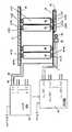
도 4는 제거가능한 콘택 구성체(contact arrangement) 및 전기적 부품을 도시한 바인더 저장 캐비넷의 일부의 확대된 부분적인 개략적 정면도이며,
도 5는 다른 제거가능한 콘택 구성체를 도시한 캐비넷 선반의 일부의 확대된 부분적인 정면도이며,
도 6은 도 5의 콘택 구성체를 추가적으로 도시한 개략적도이며,
도 7은 어드레서블 디코더를 이용하는 제 1 바인더 식별 회로의 개략도이며,
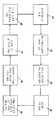
도 8은 제 1 바인더 식별 회로와 함께 사용된 바인더 위치결정 기술을 도시한 블록도이며,
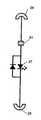
도 9는 특유 주파수의 크리스탈 공진을 이용하는 제 2 바인더 식별 회로의 개략적인 도면이며,
도 10은 도 4와 유사한 도면으로서, 제 2 바인더 식별 회로와 함께 사용되는 국부적인 전기 부품들을 도시한 도면이며,
도 11은 제 2 바인더 식별 회로와 함께 사용된 바인더 위치결정 기술을 도시한 블록도이다.1 is a perspective view of a binder of the present invention,
2 is a top view of the binder of FIG. 1 in an open position,
3 is a perspective view of a multi-shelf binder storage cabinet pair,
4 is an enlarged partial schematic front view of a portion of a binder storage cabinet showing a removable contact arrangement and electrical components, FIG.
5 is an enlarged partial front view of a portion of a cabinet shelf showing another removable contact construct,
FIG. 6 is a schematic diagram further illustrating the contact structure of FIG. 5;
7 is a schematic diagram of a first binder identification circuit using an addressable decoder,
8 is a block diagram illustrating a binder positioning technique used with a first binder identification circuit,
9 is a schematic diagram of a second binder identification circuit utilizing a crystal resonance of a specific frequency,
FIG. 10 is a view similar to FIG. 4 showing local electrical components for use with the second binder identification circuit, FIG.
11 is a block diagram illustrating a binder positioning technique used with a second binder identification circuit.
이제 도면을 참조하면, 도 1 및 도 2는 본원 발명에 따른 단일 바인더를 도시한다. 이들 도면에서 볼 수 있는 바와 같이, 바인더(10)는 전방 커버(12), 후방 커버(14) 그리고 상기 전방 커버(12) 및 상기 후방 커버(14)를 결합하는 스파인(15)을 구비한다. 복수의(3개가 도시됨) 2-피스 아치형 링(18)을 가지는 통상적인 복수-링 수동 작동식 바인더 기구(16)가 후방 커버(14)의 내측 면에 영구적으로 장착되어, 장착 엣지를 따라서 형성된 많은 수의 홀들을 가지는 서류의 삽입, 저장 및 제거를 도우며, 이때 홀들의 수는 바인더 기구(16)의 링(18)의 수에 대응한다. 스파인(15)의 내측 표면에는 기판(20a)에 의해서 지지되는 바인더 식별 회로(20)(이하에서 보다 구체적으로 설명됨), 저항 전도체(21, 22)의 쌍, 상부 저항 콘택(24), 하부 저항 콘택(25), 및 가시적인 표시부(27), 바람직하게 LED가 장착된다. 바인더(10)의 외측 측부(side)로부터 보여질 수 있도록 가시적인 표시부(27)가 스파인(15) 내에 형성된 개구부 내에 장착된다. 상부 저항 콘택(24) 및 하부 저항 콘택(25)은 도시된 바와 같은 스파인(15)의 상부 및 하부 가장자리의 약간 위쪽 및 아래쪽에서 연장하는 위치에서 스파인(15) 상에 정렬된다. 도 1 및 도 2에 도시된 실시예에서, 각각의 저항 콘택(24, 25)은 바인더 지지 선반에 의해서 지지되고 이하에서 설명되는 전도성 스트립과의 슬라이딩 결합을 촉진하기 위해서 곡선형 결합 부분(28)을 가지는 스프링 콘택이다. 이러한 구성체는 바인더가 제거가능하게 저장될 수 있고 이하에서 설명하는 선반들 상에 장착되는 전도성 스트립과 상부 저항 콘택(24) 및 하부 저항 콘택(25)이 저항식으로 결합될 수 있게 한다.
Referring now to the drawings, Figures 1 and 2 show a single binder according to the present invention. As can be seen in these figures, the
도 3은 도 1 및 도 2의 바인더(10)와 함께 사용하도록 디자인된 복수-선반 저장 캐비넷 쌍의 사시도이다. 도 3에서 도시된 바와 같이, 각각의 저장 캐비넷(30a, 30b)은 복수(2개가 도시됨)의 저장 선반(31, 32) 및 상부 선반(33)을 가진다. 복수의 바인더(10-1, 10-2, 10-N)가 해당 선반(31, 32) 상에 제거가능하게 수용된다. 각각의 선반(31, 32)은 연관된 가시적인 표시부(35), 바람직하게 LED; 그리고 설명되는 것을 목적으로 오하이오, 데이톤의 PUI Audio, Inc.로부터 입수할 수 있는 타입 AT-1220-TT-R와 같은 선택적인 가청 표시부(36)를 구비한다. 국부적인 마이크로컴퓨터를 포함하는 유닛(38) 그리고 호스트 컴퓨터로 정보를 전송하고 호스트 컴퓨터로부터 정보를 수신할 수 있는 통상적인 무선 트랜스폰더(transponder)(와이파이 유닛)가 저장 캐비넷(30a, 30b) 쌍의 적절한 부분에 장착된다.
3 is a perspective view of a multi-shelf storage cabinet pair designed for use with the
도 4는 상부 선반(33) 및 중간 선반(31)을 포함하는 바인더 저장 캐비넷(30b)의 해당 부분의 확대된 부분적인 개략적 정면도이며 제거가능한 콘택 구성체 및 연관된 전기 부품들을 도시한다. 도 4에서 볼 수 있는 바와 같이, 제 1 측방향 연장 저항 전도성 스트립(41)이 상부 선반(33)의 하부 표면에 장착되고, 제 2 측방향 연장 저항 전도성 스트립(42)이 하부 선반(31)의 상부 표면에 장착된다. 바인더(10-i)의 상부 및 하부 콘택(24-i 및 25-i)이 전도성 스트립(41, 42)들과 결합되어 바인더(10-i)가 하부 선반(31) 상에 설치될 때마다 콘택과 전도성 스트립 사이에 저항 접촉을 형성하도록, 각각의 전도성 스트립(41, 42)의 위치가 선택된다. 본질적으로 유사한 저항 전도성 스트립들이 선반(31)의 하부 표면 및 선반(32)의 상부 표면에 장착되어 동일한 전도 용량을 제공한다. 캘리포니아 산타클라라에 소재하는 Intel Corporation으로부터 입수할 수 있는 타입 AT89C2051 장치 또는 네덜란드 에인트호벤에 소재하는 NXP Semiconductors로부터 입수할 수 있는 타입 LPC 1766와 같은 국부적인 캐비넷 마이크로컴퓨터(MCU)(45)는 상부 전도성 스트립(41)에 커플링된 데이터 출력 단자(43) 및 하부 전도성 스트립(42)에 커플링된 입력 단자(44)를 가진다. 도 4의 리드 선 및 설명표(legend)에 의해서 표시된 바와 같이, 다른 입력 및 출력 쌍 단자가 다른 선반 조합의 전도성 스트립(41, 42)에 커플링된다. MCU(45)는 또한 각 선반 쌍의 가시적인 표시부(35) 및 선택적인 가청 표시부(36)에 커플링되고 도 4에서 "선반 1/LED/부저, 선반 2/LED/부저, ..., 선반 N/LED/부저" 라고 라벨링된 다른 쌍의 입력/출력 단자를 가진다. MCU(45)는 또한 전술한 무선 트랜스폰더에 의해서 설명표 "컴퓨터로"에 의해서 표시된 바와 같이 호스트 컴퓨터로 커플링된다. 이제 명확히 설명되는 바와 같이, 저항 스프링 콘택(24-i, 25-i)을 가지는 바인더(10-i)가 선반 상에 설치될 때, 이들 저항 스프링 콘택(24-i, 25-i)은 전도성 스트립(41, 42) 중에서 대응하는 하나와 결합할 것이다.
4 is an enlarged partial schematic front view of a corresponding portion of the binder storage cabinet 30b including an
도 5 및 도 6은 바인더(10-i)에 대한 저항 콘택의 대안적인 형태를 도시한다. 간결함을 위해서, MCU(45)는 이들 도면에 도시하지 않았다. 이들 도면에서 볼 수 있는 바와 같이, 스프링 콘택(24, 25)은 그 상부 및 하부 가장자리에 인접하여 바인더(10) 내에 장착된 캡쳐된 볼 및 스프링 유닛(50, 51)에 의해서 대체된다. 각각의 볼 및 스프링 유닛은 하우징(55) 내에 캡쳐된 저항 전도성 볼(53) 및 압축 스프링(54)을 포함한다. 상부 스프링 유닛(50) 내의 볼(53)은 전도체(21)를 통해서 바인더 식별 회로(20)의 하나의 단자에 저항적으로 연결되는 한편, 하부 스프링 유닛(50) 내의 볼(53)은 전도체(22)를 통해서 바인더 식별 회로(20)의 다른 단자에 저항적으로 연결된다. 볼(53)과 전도체(21, 22) 사이의 저항 연결은 하우징(55)이나 스프링(54), 또는 양자 모두를 통해서 형성될 수 있을 것이다. 사용시에, 바인더(10)가 캐비넷 선반 상에 설치될 때, 전도성 스트립(41, 42)이 볼(53)에 결합되고, 스프링(55)을 약간 압축하고, 효과적인 저항 콘택을 보장한다.
5 and 6 show alternative forms of resistance contacts for the binder 10-i. For brevity, the
도 7은 어드레서블 디코더 회로를 이용하는 제 1 바인더 식별 회로의 개략도이다. 도 7에 도시된 바와 같이, 상부 콘택(24)이 어드레스 입력 단자(A0-A7)에 의해서 내부에서 배선에 의해 접속된(hard wired) 특유 어드레스를 가지는 어드레스 디코더 칩(60)의 어드레스 입력(IN)에 저항적으로 연결된다. 어드레스 디코더 칩(60)은 바람직하게 대만, 타이페이에 소재하는 Princeton Technology Corp.으로부터 이용가능한 타입 PT2272 어드레스 디코더이다. 상부 콘택(24)은 또한 다이오드(62)를 통해서 저장 커패시터(63)에 커플링되어 MCU(45)로부터의 유입 어드레스 신호가 있을 때마다 칩(60)으로 D.C. 전력을 제공한다. 도 4에 도시된 바와 같이, 콘택(24)은 또한 MCU(45)의 출력 단자에 커플링된다. MCU(45)가 멀티-비트 어드레스를 콘택(24)으로 공급할 때, 이러한 정보는 어드레스 디코더 칩(60)의 IN 입력에 직렬로 커플링되고 디코더 칩(60)으로 배선에 의해 접속된 어드레스와 비교된다. 만약 유입 어드레스가 배선에 의해 접속된 어드레스와 매칭된다면, 디코더 칩(60)은 LED(27)를 활성화시키는 단자(VT)로 신호를 출력한다. 가시적인 표시부(27)의 활성화는 D.C. 전류를 표시부(27)를 통해서 유동시키고 콘택(25) 및 도 4에 도시된 복귀 경로를 통해서 MCU(45)로 다시 유동시킨다. 이러한 전류 유동은 MCU(45)에 의해서 감지되고, 이는 그 후 선반 LED(35) 그리고 매칭된 어드레스 디코더 칩(60)을 가지는 바인더(10-i)가 위치되는 선반에 대한 선택적인 가청 표시부(36)를 활성화킨다. MCU(45)는 또한 어드레스 매치가 탐지되었을 때 "Found(발견)" 신호를 호스트 컴퓨터로 전송한다.
7 is a schematic diagram of a first binder identification circuit using an addressable decoder circuit. As shown in Fig. 7, the address input IN of the
도 8은 도 7의 제 1 바인더 식별 회로와 함께 사용되는 바인더 위치결정 기술을 도시한 블록도이다. 도 8에 도시된 바와 같이, 프로세스는 흐름도 블록(81)에서 작업자가 호스트 컴퓨터를 턴온하는 것으로 시작된다. 그 후에, 블록(82)에서 작업자는 바인더 또는 바인더 내에 저장된 서류의 시스템 식별을 입력한다. 다음에, 호스트 컴퓨터는 특정된 서류를 포함하는 바인더의 일련 번호 또는 특정된 바인더의 일련 번호에 대한 시스템 데이터베이스를 탐색한다(블록 83). 바인더 일련 번호가 위치결정되면, 호스트 컴퓨터는 찾고자 하는 바인더의 대응하는 어드레스 코드를 생성한다(블록 84). 이러한 코드는 찾고자 하는 바인더에 수용된 디코더 칩(60)에 배선에 의해 접속된 코드와 매칭된다. 이어서, 이러한 어드레스 코드는 시스템 내의 모든 MCU(45)로 제공된다(broadcast). 이어서, 각각의 MCU(45)는 수신된 어드레스 코드를 각 선반에 대한 코드 전도체(41)로 출력하고 디코더 칩들 중 하나로부터 포지티브(긍정적인) 응답을 대기한다(블록 86). 만약 MCU(45)가 포지티브 응답(가시적인 표시부(27)들 중 하나를 통해서 유동하는 전류)을 감지한다면, MCU(45)는 그 후 대응 선반 LED(35) 및 선택적인 부저(36)를 활성화시키고(블록 87) 그리고 "Found" 신호를 생성하며, 그 신호는 이어서 유닛(38) 내의 와이파이 유닛에 의해서 호스트 컴퓨터로 전송된다(블록 88). 이어서, 작업자는 활성화된 선반 LED(35)를 가지는 선반에 대한 바인더 저장 영역 주위를 살펴볼 수 있고, 해당 선반으로 다가갈 수 있으며 활성화된 LED(27)를 가지는 바인더를 찾아볼 수 있다. 만약 선택적인 가청 표시부(36)가 제공된다면(통상적으로, 비교적 큰 바인더 저장 영역 또는 밝게 조명된 영역에 대해), 작업자는 조명된 선반 LED(35)가 시각적으로 위치결정될 때까지 가청 음향의 방향으로 진행할 수 있을 것이다.
FIG. 8 is a block diagram illustrating a binder positioning technique used with the first binder identification circuit of FIG. 7. As shown in FIG. 8, the process begins at
스윕(sweep) 어드레스 모드에서 호스트 컴퓨터를 작동시킴으로써 바인더(10-i)의 전체 집합체의 무결성이 신속하게 체크될 수 있다. 가능한 어드레스들의 전체 범위에 걸쳐 어드레스들이 스위핑됨에 따라, 캐비넷의 집합체 내에 선택적으로 존재하는 모든 바인더 식별 회로(20)는 대응 바인더 LED(27)를 활성화시킴으로써 응답할 것이고 이는 대응하는 단일 보드 컴퓨터(45)에 의해서 탐지될 것이고 "Found" 신호가 다시 호스트 컴퓨터로 전송될 것이다. 임의의 망실 또는 비-기능 바인더 식별 회로(20)의 어드레스는 결과적으로 "Found" 신호를 생성하지 않을 것이고, 이러한 응답의 누락은 시스템 호스트 컴퓨터에 의해서 탐지될 것이다. 주어진 특정 어드레스의 작동적인 바인더 식별 회로(20)의 이러한 부재는, 비-응답 바인더 식별 회로의 어드레스를 통지함으로써, 시스템 호스트 컴퓨터에 의해서 시스템 호스트 컴퓨터 내의 바인더 식별과 상호연관될 수 있을 것이다.
By operating the host computer in sweep address mode, the integrity of the entire collection of binders 10-i can be quickly checked. As addresses are swept across the entire range of possible addresses, all
도 9는 단일 특유 주파수 크리스탈을 이용한 제 2 바인더 식별 회로의 개략도이다. 도 9에 도시된 바와 같이, 상부 콘택(24)은 공진 주파수를 가지는 크리스탈(91)의 제 1 단자에 저항적으로 연결된다. 크리스탈(91)의 다른 단자는 LED(27)의 양극(anode) 단자에 커플링된다. LED(27)의 음극(cathode)은 하부 콘택(25)에 커플링된다. 크리스탈의 주파수를 가지는 r.f. 신호가 2개의 크리스탈 단자에 걸쳐 인가될 때, 크리스탈이 공진할 것이고 전류가 LED(27)를 통해서 유동할 것이며, 그에 따라 LED를 조명할 것이다. 각각의 바인더 식별 회로 내의 크리스탈(91)은 특유한 그리고 시스템 내의 모든 다른 바인더 식별 회로 내의 크리스탈(91)과 상이한 공진 주파수를 가지며, 그리고 호스트 컴퓨터는 일련 번호에 의해서 개별적인 바인더(10-i)와 상호 관련되는 크리스탈 주파수의 중요 리스트를 포함한다.
9 is a schematic diagram of a second binder identification circuit using a single unique frequency crystal. As shown in FIG. 9, the
도 10은 도 9의 크리스탈 회로와 함께 채용되는 전기 부품들 및 제거가능한 콘택 구성체를 도시하는, 바인더 저장 캐비넷의 일부의 확대된 부분 정면 개략도이다. 도 9에 도시된 바와 같이, 저항 전도성 스트립(41, 42), 선반의 가시적인 표시부(35), 및 선택적인 선반의 가청 표시부(36)가 본질적으로 전술한 도 4의 정렬과 동일한 물리적인 방식으로 정렬된다. 그러나 도 10의 실시예에서, MCU(45)는 전도성 스트립(41)으로 데이터를 공급하지 않는다. 그 대신에, 주어진 캐비넷 내의 각각의 선반 쌍의 상부 전도성 스트립(41) 및 하부 전도성 스트립(42)에 커플링된 r.f. 신호 단자(94, 95)의 쌍을 가지는 R.F. 발생기(93)가 제공된다. R.F. 발생기(93)는, 호스트 컴퓨터로부터 원하는 주파수 지시 신호를 수신하는 것에 응답하여, 허용된 주파수의 미리 결정된 범위, 예를 들어 2 내지 20 mHz에 걸쳐 단일 주파수 r.f. 신호를 생성할 수 있는 통상적인 장치이다. MCU(45)는, 희망 주파수를 가지는 크리스탈이 주어진 선반 상의 바인더 식별 회로들 중 하나에서 공진한다는 것을 나타내는 R.F. 발생기(93)로부터의 신호를 수신하는 것에 응답하여, 선반 가시적인 표시부(35) 및 선택적인 선반 가청 표시부(36)의 작동을 제어한다.
FIG. 10 is an enlarged partial front schematic view of a portion of a binder storage cabinet, showing electrical components and removable contact constructions employed with the crystal circuit of FIG. 9. FIG. As shown in FIG. 9, the resistive
도 11은 도 9의 제 2 바인더 식별 회로와 함께 사용되는 바인더 위치결정 기술을 도시한 블록도이다. 도 11에 도시된 바와 같이, 프로세스는 흐름도 블록(101)에서 작업자가 호스트 컴퓨터를 켜는 것으로 시작된다. 그 후에, 블록(102)에서, 작업자가 바인더 또는 바인더 내에 저장된 서류의 시스템 식별을 입력한다. 다음에, 호스트 컴퓨터는 특정 서류를 포함하는 바인더의 일련 번호 또는 특정 바인더의 일련 번호에 대한 시스템 데이터베이스를 탐색한다(블록 103). 이들 단계는 본질적으로 도 8의 단계(81-83)와 동일하다. 바인더 일련 번호가 위치결정되면, 호스트 컴퓨터는 찾고자 하는 바인더의 대응하는 주파수 코드를 생성한다(블록 104). 이러한 주파수는 찾고자 하는 바인더에 수용된 바인더 식별 회로 내의 크리스탈의 주파수와 매칭된다. 이러한 주파수 코드는 그 후 시스템 내의 모든 R.F. 발생기(93)로 제공된다(broadcast). 이어서, 각각의 R.F. 발생기(93)는 연관된 캐비넷 내의 모든 선반 쌍들에 대한 희망 주파수의 r.f. 신호를 생성한다(블록 106). 만약 특정 주파수의 크리스탈을 가지는 바인더 식별 회로가 캐비넷 내의 선반들 중 하나 상에서 위치된다면, 크리스탈은 공진할 것이고 대응하는 LED(27)가 켜지게 될 것이다(블록 107). 이러한 조건은 공진 크리스탈을 가지는 바인더 식별 회로를 포함하는 캐비넷 내의 R.F. 발생기(93)에 의해서 감지되고, 그러한 조건은 R.F. 발생기(93)에 의해서 MCU(45)로 보고된다. 응답시에, MCU(45)는 찾는 바인더(10-i)를 포함하는 선반에 대해서 가시적인 선반 표시부(35) 및 선택적으로 가청 선반 표시부(36)를 활성화시키고(블록 108), 그리고 유닛(38) 내의 와이파이 장치에 의해서 호스트 컴퓨터로 전송되는 "Found" 신호를 생성한다(블록 109). 이어서, 작업자는 활성화된 선반 LED(35)를 가지는 선반에 대한 바인더 저장 영역 주위를 살펴볼 수 있고, 해당 선반으로 다가갈 수 있으며 활성화된 LED(27)를 가지는 바인더를 찾아볼 수 있다. 만약 선택적인 가청 표시부(36)가 제공된다면(통상적으로, 비교적 큰 바인더 저장 영역 또는 밝게 조명된 영역에 대해), 작업자는 조명된 선반 LED(35)가 시각적으로 위치결정될 때까지 가청 음향의 방향으로 진행할 수 있을 것이다.
FIG. 11 is a block diagram illustrating a binder positioning technique used with the second binder identification circuit of FIG. 9. As shown in FIG. 11, the process begins at
각각의 캐비넷 내의 R.F. 발생기(93)는 바인더 관리 시스템 내의 제 1 크리스탈 공진 주파수로 시작하고, 시스템 내의 마지막 크리스탈 공진 주파수로 종료되는 스위핑된(swept) 모드에서 R.F. 신호를 발생할 수 있는 스윕 주파수 발생기를 포함할 수 있다. 그러한 신호 발생기를 이용하여, R.F. 발생기(93)가 스윕 모드에서 작동하도록 명령함으로써, 바인더의 전체 집합체의 무결성이 신속하게 체크될 수 있다. 신호 주파수가 전체 범위에 걸쳐 스위핑되기 때문에, 주어진 캐비넷 내에 존재하는 모든 바인더 식별 회로가 그들의 각각의 주파수에서 공진할 것이고 이는 통상적인 R.F. 탐지기 회로를 이용하여 각각의 캐비넷 내의 마이크로컴퓨터 유닛(45)에 의해서 탐지될 수 있다. 임의의 망실 바인더는 응답하지 않을 것이고, 이는 또한 동일한 회로를 이용하여 각각의 캐비넷 내의 마이크로컴퓨터 유닛(45)에 의해서 탐지될 수 있을 것이다. 망실된 것으로 탐지된 임의의 바인더는 각 캐비넷 내에서 주어진 마이크로컴퓨터 유닛(45)에 의해서 시스템 호스트 컴퓨터로 보고될 수 있고 그리고, 비-응답 바인더 식별 회로의 주파수를 통지함으로써, 시스템 호스트 컴퓨터에 의해서 컴퓨터 내의 바인더 식별과 연관된다.
The
시스템은 초기에 몇 가지 다른 방식들로 바인더들을 위해서 구성될 수 있을 것이다. 가장 기본적인 방식은 단일 바인더(10)를 캐비넷 내의 선반 상에 위치시키고, 캐비넷 R.F. 신호 발생기(93)가 허용된 주파수 범위를 스위핑하게 하고, 바인더 내의 크리스탈이 공진하는 주파수를 통지하고(note), 주파수 번호를 마이크로컴퓨터 유닛(45) 메모리 내의 리스트 내로 입력하고, 바인더를 제거하며, 다른 바인더(10)를 삽입하고, 일련의 베이스들 상에서 원하는 모든 바인더들에 대해서 이러한 프로세스를 반복한다. 일단 모든 바인더들이 프로세싱되면, 적절한 바인더 식별 정보가 주어진 캐비넷의 마이크로컴퓨터 유닛(45)으로부터 시스템 호스트 컴퓨터로 전송된다. 이러한 방법은 초기에 비교적 적은 수의 바인더들이 필요하고 기존의 바인더가 없는 새로운 시스템에 대해서 잘 작동한다. 보다 유용한 기술은 제 1 바인더를 선반 상으로 삽입하고, 허용된 R.F. 주파수를 스위핑하며, 제 1 바인더에 크리스탈의 공진 주파수를 통지하고, 새로운 리스트에 번호를 입력하는 것; 제 1 바인더를 제거하지 않고 제 2 바인더를 선반 상으로 삽입하며, 주파수를 스위핑하고, 새로운 바인더 내의 크리스탈의 공진 주파수를 리스트에 부가하는 것; 제 3 바인더를 선반 상으로 삽입하고, 주파수를 스위핑하며, 제 3 바인더 내의 크리스탈의 공진 주파수를 리스트에 부가하는 것; 등등이다. 각각의 새로운 바인더들이 선반 상으로 삽입됨에 따라, 마이크로컴퓨터 유닛(45)은 이미 식별된 주파수의 실행중인 리스트를 가지고, 각각의 크리스탈 주파수가 특유의 것이기 때문에, 중복은 있을 수 없다.
The system may initially be configured for binders in several different ways. The most basic approach is to place a
전술한 어드레서블 디코더 회로를 이용하는 시스템은 특유 주파수의 단일 크리스탈을 이용하는 R.F. 바인더 식별 회로와 관련하여 전술한 것과 유사한 방식으로 초기에 구성될 수 있다. 본질적인 차이는, 스위핑된 주파수 기술을 채용하는 대신에, 스위핑된 어드레스 기술을 채용하는 것이다. 이러한 기술의 경우에, 호스트 컴퓨터는 시스템 내에서 허용가능한 어드레스들의 전체 세트를 순차적으로 생성하고, 시스템 내의 각각의 MCU(45)로부터의 응답을 통지하며 이를 바인더 식별 정보와 상호 관련시킨다.
The system using the addressable decoder circuit described above may be initially configured in a manner similar to that described above with respect to the RF binder identification circuit using a single crystal of a specific frequency. The essential difference is that instead of employing the swept frequency technique, it employs the swept address technique. In the case of this technique, the host computer sequentially generates the full set of allowable addresses in the system, notifies the response from each
전술한 바인더 관리 시스템은 공지된 바인더 관리 시스템을 넘어서는 몇 가지 이점을 제공한다. 첫 번째로, 찾는 바인더가 위치결정될 때까지 모든 바인더 라벨들을 시각적으로 검사할 필요가 없이, 주어진 바인더가 바인더 저장 영역 내에 신속하게 위치결정될 수 있다. 또한, 잘못 채워진 바인더들을 찾기 위해서 그리고 시스템으로부터 망실된 바인더들을 식별하기 위해서, 바인더 관리 시스템의 무결성이 원격적으로 완전히 테스트될 수 있다.
The binder management system described above provides several advantages over known binder management systems. First, a given binder can be quickly positioned within the binder storage area without having to visually inspect all the binder labels until the finding binder is located. In addition, in order to find misfilled binders and to identify lost binders from the system, the integrity of the binder management system can be remotely fully tested.
비록 전술한 바가 본원 발명의 바람직한 실시예의 전체적이고 완전한 설명을 제공하지만, 여러 가지 변형예, 대안적인 구성 및 균등물들이 당업자에 의해 안출될 것이다. 예를 들어, 본원 발명이 특정 R.F. 주파수를 참조하여 설명되었지만, 시스템 디자이너의 선호도에 따라서 다른 주파수가 채용될 수 있을 것이다. 또한, 전도성 스트립(41, 42)이 선반을 따라서 측방향으로 배치된 것으로 도시되어 있지만, 각각의 스트립은 연관된 선반 표면의 내측으로 그리고 미리 결정된 양만큼 측방향으로 이격되어 연장하는 복수의 상호연결된 스트립 부분들로서 구성될 수 있을 것이다. 그러한 변경에서, 바인더들에 대한 보다 큰 기계적 안정성 및 바인더들에 대한 미리 결정된 측방향 간격을 제공하기 위해서, 콘택(24, 25)은 전도성 스트립 부분들과의 형상 결합을 제공하도록 내부에 형성되는 홈을 구비할 수 있다. 또한, 바인더 기구(16)가 후방 커버(14)의 내측 표면상에 장착되는 것으로 설명되고 도시되었지만, 필요한 경우에, 그러한 바인더 기구는 전방 커버(12)의 내측 표면상에 장착될 수 있고, 또는 스파인(15)의 내측 표면상에 장착될 수 있을 것이다. 스파인(15)의 내측 표면상에 장착된다면, 일반적으로 전도성 바인더 기구가 요소들(20, 20a, 21, 22, 24, 25, 27 및 28)로부터 전기적으로 절연되도록 주의를 기울여야 할 것이다. 또한, 필요한 경우에, 본원 발명은 내부 또는 외부 컴퓨터 네트워크를 이용하여 다른 물리적 장소에 배치된 많은 캐비넷의 바인더 관리 시스템을 관리하는데 이용될 수 있을 것이다. 그에 따라, 전술한 내용은 특허청구범위에서 규정되는 본원 발명을 한정하는 것으로 간주되지 않아야 할 것이다.Although the foregoing provides a complete and complete description of the preferred embodiments of the invention, various modifications, alternative configurations, and equivalents will be devised by those skilled in the art. For example, the present invention is directed to certain R.F. Although described with reference to frequency, other frequencies may be employed depending on the preference of the system designer. Furthermore, although
Claims (19)
Translated fromKorean전방 커버, 후방 커버 그리고 상기 전방 커버 및 상기 후방 커버를 결합하는 스파인을 구비하는 바인더 바디;
상기 바인더 바디의 내부에 장착되는 바인더 기구;
바인더의 외부로부터 볼 수 있는 위치에서 상기 바인더 바디 상에 장착되는 가시적인 표시부;
상기 바인더 바디에 의해서 지지되고 소오스로부터의 바인더 식별 신호를 수신하기 위해서 상기 바인더 바디의 외부로 부분적으로 연장하는 콘택 부분을 가지는 제 1 및 제 2 저항 콘택 부재; 그리고
상기 바인더 바디 상에 장착되고 상기 제 1 및 제 2 저항 콘택 부재 그리고 상기 가시적인 표시부에 커플링되어, 상기 바인더가 찾고 있는 바인더라는 것을 수신된 바인더 식별 신호가 나타낼 때, 상기 가시적인 표시부를 활성화시키기 위한 바인더 식별 회로를 포함하는
탐색가능한 바인더.
As a searchable binder for use in a binder management system:
A binder body having a front cover, a rear cover and a spine for coupling the front cover and the rear cover;
A binder mechanism mounted inside the binder body;
A visible display unit mounted on the binder body at a position visible from the outside of the binder;
First and second resistive contact members supported by the binder body and having contact portions partially extending out of the binder body to receive a binder identification signal from a source; And
Mounted on the binder body and coupled to the first and second resistive contact members and the visible display to activate the visible display when a received binder identification signal indicates that the binder is the binder being searched for. A binder identification circuit for
Navigable Binder.
상기 바인더 기구는 상기 후방 커버의 내측 표면에 장착되는
탐색가능한 바인더.
The method of claim 1,
The binder mechanism is mounted to the inner surface of the rear cover
Navigable Binder.
상기 가시적인 표시부는 상기 스파인 상에 장착되는
탐색가능한 바인더.
The method of claim 1,
The visible indicator is mounted on the spine
Navigable Binder.
상기 스파인은 상단부 및 하단부 내에서 종료되는 내측 표면을 가지며; 상기 제 1 저항 콘택 부재는 상기 상단부에 인접하여 상기 스파인의 상기 내측 표면상에 장착되고 상기 제 2 저항 콘택 부재는 상기 하단부에 인접하여 상기 스파인의 상기 내측 표면상에 장착되는
탐색가능한 바인더.
The method of claim 1,
The spine has an inner surface that terminates within the top and bottom portions; The first resistance contact member is mounted on the inner surface of the spine adjacent to the upper end and the second resistance contact member is mounted on the inner surface of the spine adjacent to the lower end.
Navigable Binder.
상기 제 1 및 제 2 저항 콘택 부재는 각각 상기 스파인의 외측으로 연장하는 곡선형 외측 단부 내에서 종료되는 바디 부분을 포함하는,
탐색가능한 바인더.
The method of claim 4, wherein
The first and second resistance contact members each comprising a body portion terminating in a curved outer end extending outwardly of the spine;
Navigable Binder.
상기 제 1 및 제 2 저항 콘택 부재는 각각 내측 부피를 가지는 하우징, 상기 내측 부피 내에 이동가능하게 수용되는 볼 콘택, 그리고 상기 볼 콘택과 상기 하우징 사이에서 캡쳐되어 상기 볼 콘택을 외측 방향으로 편향시키기 위한 편향 스프링을 포함하는
탐색가능한 바인더.
The method of claim 4, wherein
The first and second resistance contact members each have a housing having an inner volume, a ball contact movably received within the inner volume, and captured between the ball contact and the housing to deflect the ball contact in an outward direction. With deflection spring
Navigable Binder.
상기 바인더 식별 신호는 연관된 바인더 특유의 바인더 어드레스를 포함하고; 상기 바인더 식별 회로는 어드레서블 디코더를 포함하는
탐색가능한 바인더.
The method of claim 1,
The binder identification signal includes an associated binder specific binder address; The binder identification circuit includes an addressable decoder
Navigable Binder.
상기 바인더 식별 신호는 연관된 바인더 특유의 주파수를 가지는 r.f. 신호를 포함하고; 상기 바인더 식별 회로는 상기 연관된 바인더 특유의 주파수와 동일한 공진 주파수를 가지는 크리스탈을 포함하는
탐색가능한 바인더.
The method of claim 1,
The binder identification signal comprises an rf signal having an associated binder specific frequency; The binder identification circuit includes a crystal having a resonance frequency equal to a frequency specific to the associated binder.
Navigable Binder.
상기 가시적인 표시부가 LED를 포함하는
탐색가능한 바인더.
The method of claim 1,
The visible display portion includes an LED
Navigable Binder.
복수의 탐색가능한 바인더를 위한 저장 캐비넷으로서, 상기 캐비넷은 상부 선반 및 하부 선반을 가지며, 상기 상부 선반은 하부 표면을 가지고 상기 하부 선반은 상부 표면을 가지는, 저장 캐비넷;
상기 상부 선반의 상기 하부 표면상에 장착된 제 1 저항 전도성 부재;
상기 하부 선반의 상기 상부 표면상에 장착된 제 2 저항 전도성 부재로서, 상기 제 1 및 제 2 저항 전도성 부재가 소오스로부터 바인더 식별 신호를 수신하도록 구성되는, 제 2 저항 전도성 부재; 그리고
상기 하부 선반 상에 제거가능하게 수용되도록 구성된 탐색가능한 바인더를 포함하고,
상기 탐색가능한 바인더는 전방 커버, 후방 커버 그리고 상기 전방 커버 및 상기 후방 커버를 결합하는 스파인을 구비하는 바인더 바디; 상기 바인더 바디의 내부에 장착되는 바인더 기구; 상기 바인더가 상기 하부 선반 상에 설치될 때, 상기 바인더의 외부로부터 볼 수 있는 위치에서 상기 바인더 바디 상에 장착되는 가시적인 표시부; 제 1 및 제 2 저항 콘택 부재로서, 상기 바인더 바디에 의해서 지지되고 상기 제 1 및 제 2 저항 전도성 부재 중 하나 이상에 존재하는 바인더 식별 신호가 제 1 및 제 2 저항 콘택 부재 중 하나 이상으로 전송되도록 상기 바인더가 하부 선반 상에 설치될 때 상기 제 1 및 제 2 저항 전도성 부재와 저항 결합하기 위해서 상기 바인더 바디의 외부로 부분적으로 연장하는 콘택 부분들을 가지는, 제 1 및 제 2 저항 콘택 부재; 그리고 상기 바인더 바디 상에 장착되고 상기 제 1 및 제 2 저항 콘택 부재 그리고 상기 가시적인 표시부에 커플링되어, 상기 바인더가 찾고 있는 바인더라는 것을 수신된 바인더 식별 신호가 나타낼 때, 상기 가시적인 표시부를 활성화시키기 위한 바인더 식별 회로를 포함하는
조합체.
As a combination:
A storage cabinet for a plurality of searchable binders, the cabinet having an upper shelf and a lower shelf, the upper shelf having a lower surface and the lower shelf having an upper surface;
A first resistive conductive member mounted on the lower surface of the upper shelf;
A second resistive conductive member mounted on the upper surface of the lower shelf, wherein the first and second resistive conductive members are configured to receive a binder identification signal from a source; And
A navigable binder configured to be removably received on the bottom shelf,
The navigable binder comprises: a binder body having a front cover, a rear cover and a spine coupling the front cover and the rear cover; A binder mechanism mounted inside the binder body; A visible display unit mounted on the binder body in a position visible from the outside of the binder when the binder is installed on the lower shelf; First and second resistive contact members, wherein a binder identification signal supported by the binder body and present in at least one of the first and second resistive conductive members is transmitted to at least one of the first and second resistive contact members. First and second resistive contact members having contact portions partially extending out of the binder body to resistively engage the first and second resistive conductive members when the binder is installed on a lower shelf; And is coupled on the binder body and coupled to the first and second resistive contact members and the visible display to activate the visible display when a received binder identification signal indicates that the binder is the binder being searched for. A binder identification circuit for
Combination.
상기 가시적인 표시부가 상기 스파인 상에 장착되는
조합체.
11. The method of claim 10,
The visible indicator is mounted on the spine
Combination.
상기 스파인은 상단부 및 하단부 내에서 종료되는 내측 표면을 가지며; 상기 제 1 저항 콘택 부재는 상기 상단부에 인접하여 상기 스파인의 상기 내측 표면상에 장착되고 상기 제 2 저항 콘택 부재는 상기 하단부에 인접하여 상기 스파인의 상기 내측 표면상에 장착되는
조합체.
11. The method of claim 10,
The spine has an inner surface that terminates within the top and bottom portions; The first resistance contact member is mounted on the inner surface of the spine adjacent to the upper end and the second resistance contact member is mounted on the inner surface of the spine adjacent to the lower end.
Combination.
상기 제 1 및 제 2 저항 콘택 부재는 각각 상기 스파인의 외측으로 연장하는 곡선형 외측 단부 내에서 종료되는 바디 부분을 포함하는,
조합체.
13. The method of claim 12,
The first and second resistance contact members each comprising a body portion terminating in a curved outer end extending outwardly of the spine;
Combination.
상기 제 1 및 제 2 저항 콘택 부재는 각각 내측 부피를 가지는 하우징, 상기 내측 부피 내에 이동가능하게 수용되는 볼 콘택, 그리고 상기 볼 콘택과 상기 하우징 사이에서 캡쳐되어 상기 볼 콘택을 외측 방향으로 편향시키기 위한 편향 스프링을 포함하는
조합체.
13. The method of claim 12,
The first and second resistance contact members each have a housing having an inner volume, a ball contact movably received within the inner volume, and captured between the ball contact and the housing to deflect the ball contact in an outward direction. With deflection spring
Combination.
상기 바인더 식별 신호는 연관된 바인더 특유의 바인더 어드레스를 포함하고; 상기 바인더 식별 회로는 어드레서블 디코더를 포함하는
조합체.
11. The method of claim 10,
The binder identification signal includes an associated binder specific binder address; The binder identification circuit includes an addressable decoder
Combination.
상기 바인더 식별 신호는 연관된 바인더 특유의 주파수를 가지는 r.f. 신호를 포함하고; 상기 바인더 식별 회로는 상기 연관된 바인더 특유의 주파수와 동일한 공진 주파수를 가지는 크리스탈을 포함하는
조합체.
11. The method of claim 10,
The binder identification signal comprises an rf signal having an associated binder specific frequency; The binder identification circuit includes a crystal having a resonance frequency equal to a frequency specific to the associated binder.
Combination.
상기 가시적인 표시부는 LED를 포함하는
조합체.
11. The method of claim 10,
The visible display portion includes an LED
Combination.
상기 상부 및 하부 선반들 중 하나의 선반 상에서 찾고 있는 바인더의 존재를 시각적으로 나타내기 위해서 상기 상부 선반 및 하부 선반 중 하나 이상에 장착되는 가시적인 표시부를 더 포함하는
조합체.
11. The method of claim 10,
And further comprising a visual indicator mounted to at least one of the upper shelf and the lower shelf to visually indicate the presence of a binder looking on one of the upper and lower shelves.
Combination.
상기 상부 및 하부 선반들 중 하나의 선반 상에서 찾고 있는 바인더의 존재를 청각적으로 나타내기 위해서 상기 상부 선반 및 하부 선반 중 하나 이상에 장착되는 가청 표시부를 더 포함하는
조합체.11. The method of claim 10,
And further comprising an audible indicator mounted to at least one of the upper shelf and the lower shelf to audibly indicate the presence of a binder looking on one of the upper and lower shelves.
Combination.
Priority Applications (1)
| Application Number | Priority Date | Filing Date | Title |
|---|---|---|---|
| KR1020120017078AKR101287053B1 (en) | 2012-02-20 | 2012-02-20 | Searchable binder |
Applications Claiming Priority (1)
| Application Number | Priority Date | Filing Date | Title |
|---|---|---|---|
| KR1020120017078AKR101287053B1 (en) | 2012-02-20 | 2012-02-20 | Searchable binder |
Publications (1)
| Publication Number | Publication Date |
|---|---|
| KR101287053B1true KR101287053B1 (en) | 2013-07-17 |
Family
ID=48997556
Family Applications (1)
| Application Number | Title | Priority Date | Filing Date |
|---|---|---|---|
| KR1020120017078AExpired - Fee RelatedKR101287053B1 (en) | 2012-02-20 | 2012-02-20 | Searchable binder |
Country Status (1)
| Country | Link |
|---|---|
| KR (1) | KR101287053B1 (en) |
Citations (4)
| Publication number | Priority date | Publication date | Assignee | Title |
|---|---|---|---|---|
| JPH1111614A (en)* | 1997-06-20 | 1999-01-19 | Asahi Denshi Kenkyusho:Kk | Sorting management method for object to be retrieved such as card, and device thereof |
| JPH1159833A (en)* | 1997-08-26 | 1999-03-02 | Nippon Filing Co Ltd | Clinical chart file retrieval device |
| JP2004351915A (en)* | 2003-03-31 | 2004-12-16 | Kokuyo Co Ltd | Filing tool |
| JP2005335129A (en)* | 2004-05-25 | 2005-12-08 | Sharp Corp | Document holding equipment, document management system |
- 2012
- 2012-02-20KRKR1020120017078Apatent/KR101287053B1/ennot_activeExpired - Fee Related
Patent Citations (4)
| Publication number | Priority date | Publication date | Assignee | Title |
|---|---|---|---|---|
| JPH1111614A (en)* | 1997-06-20 | 1999-01-19 | Asahi Denshi Kenkyusho:Kk | Sorting management method for object to be retrieved such as card, and device thereof |
| JPH1159833A (en)* | 1997-08-26 | 1999-03-02 | Nippon Filing Co Ltd | Clinical chart file retrieval device |
| JP2004351915A (en)* | 2003-03-31 | 2004-12-16 | Kokuyo Co Ltd | Filing tool |
| JP2005335129A (en)* | 2004-05-25 | 2005-12-08 | Sharp Corp | Document holding equipment, document management system |
Similar Documents
| Publication | Publication Date | Title |
|---|---|---|
| US8717143B2 (en) | Searchable binder | |
| US5977875A (en) | Collective objects management system using R.F. object indentification | |
| US20140191633A1 (en) | Storage container for electronically addressable file folders and documents | |
| US5771003A (en) | Locating system and process | |
| US8994534B2 (en) | Documents management using remote document location and retrieval | |
| US20150206094A1 (en) | Asset tracking system and method incorporating switchable antenna | |
| KR20100028334A (en) | Ubiqutious library management system | |
| US8471717B2 (en) | Collective objects management system with object identification using addressable decoder units | |
| RU2007147923A (en) | CONTAINER AND TOOL TRACKING METHOD | |
| US6348864B1 (en) | Organizer management system using R.F. identification | |
| US8115629B2 (en) | Collective objects management system using R.F. object identification with multiple crystals | |
| US6664895B2 (en) | R.F. suppression technique for collective objects management system using R.F. object identification | |
| US9875460B2 (en) | Removably sustended electronically addressable object and system | |
| CN103164677A (en) | File management by the adoption of telefile alignment and retrieval | |
| US9884507B2 (en) | Searchable binder with inductive address code transfer | |
| CN102783825A (en) | Intelligent newspaper cabinet | |
| KR101287053B1 (en) | Searchable binder | |
| JP6014332B2 (en) | Searchable binder | |
| EP2617322B1 (en) | Searchable binder | |
| TWI537148B (en) | Binder management system | |
| CN103253033B (en) | The loose-leaf binder that can search for | |
| JP5890135B2 (en) | Collective object management system with object identification using addressable decoder unit | |
| CN1171165C (en) | Management system for files in cabinet | |
| US9792786B1 (en) | Dual mount searchable binder | |
| US11023854B1 (en) | Electronically addressable document receptacle with A-polar connectivity |
Legal Events
| Date | Code | Title | Description |
|---|---|---|---|
| A201 | Request for examination | ||
| PA0109 | Patent application | St.27 status event code:A-0-1-A10-A12-nap-PA0109 | |
| PA0201 | Request for examination | St.27 status event code:A-1-2-D10-D11-exm-PA0201 | |
| D13-X000 | Search requested | St.27 status event code:A-1-2-D10-D13-srh-X000 | |
| D14-X000 | Search report completed | St.27 status event code:A-1-2-D10-D14-srh-X000 | |
| R17-X000 | Change to representative recorded | St.27 status event code:A-3-3-R10-R17-oth-X000 | |
| E701 | Decision to grant or registration of patent right | ||
| PE0701 | Decision of registration | St.27 status event code:A-1-2-D10-D22-exm-PE0701 | |
| GRNT | Written decision to grant | ||
| PR0701 | Registration of establishment | St.27 status event code:A-2-4-F10-F11-exm-PR0701 | |
| PR1002 | Payment of registration fee | St.27 status event code:A-2-2-U10-U11-oth-PR1002 Fee payment year number:1 | |
| PG1601 | Publication of registration | St.27 status event code:A-4-4-Q10-Q13-nap-PG1601 | |
| FPAY | Annual fee payment | Payment date:20160624 Year of fee payment:4 | |
| PR1001 | Payment of annual fee | St.27 status event code:A-4-4-U10-U11-oth-PR1001 Fee payment year number:4 | |
| P22-X000 | Classification modified | St.27 status event code:A-4-4-P10-P22-nap-X000 | |
| FPAY | Annual fee payment | Payment date:20170628 Year of fee payment:5 | |
| PR1001 | Payment of annual fee | St.27 status event code:A-4-4-U10-U11-oth-PR1001 Fee payment year number:5 | |
| FPAY | Annual fee payment | Payment date:20180710 Year of fee payment:6 | |
| PR1001 | Payment of annual fee | St.27 status event code:A-4-4-U10-U11-oth-PR1001 Fee payment year number:6 | |
| FPAY | Annual fee payment | Payment date:20190710 Year of fee payment:7 | |
| PR1001 | Payment of annual fee | St.27 status event code:A-4-4-U10-U11-oth-PR1001 Fee payment year number:7 | |
| PR1001 | Payment of annual fee | St.27 status event code:A-4-4-U10-U11-oth-PR1001 Fee payment year number:8 | |
| PC1903 | Unpaid annual fee | St.27 status event code:A-4-4-U10-U13-oth-PC1903 Not in force date:20210712 Payment event data comment text:Termination Category : DEFAULT_OF_REGISTRATION_FEE | |
| PC1903 | Unpaid annual fee | St.27 status event code:N-4-6-H10-H13-oth-PC1903 Ip right cessation event data comment text:Termination Category : DEFAULT_OF_REGISTRATION_FEE Not in force date:20210712 |