KR101286281B1 - Belt drive type surgical stapling enteroanastomotic device - Google Patents
Belt drive type surgical stapling enteroanastomotic deviceDownload PDFInfo
- Publication number
- KR101286281B1 KR101286281B1KR1020110094669AKR20110094669AKR101286281B1KR 101286281 B1KR101286281 B1KR 101286281B1KR 1020110094669 AKR1020110094669 AKR 1020110094669AKR 20110094669 AKR20110094669 AKR 20110094669AKR 101286281 B1KR101286281 B1KR 101286281B1
- Authority
- KR
- South Korea
- Prior art keywords
- lower jaw
- wire
- jaw
- pulley
- wedge
- Prior art date
- Legal status (The legal status is an assumption and is not a legal conclusion. Google has not performed a legal analysis and makes no representation as to the accuracy of the status listed.)
- Expired - Fee Related
Links
Images


Classifications
- A—HUMAN NECESSITIES
- A61—MEDICAL OR VETERINARY SCIENCE; HYGIENE
- A61B—DIAGNOSIS; SURGERY; IDENTIFICATION
- A61B17/00—Surgical instruments, devices or methods
- A61B17/11—Surgical instruments, devices or methods for performing anastomosis; Buttons for anastomosis
- A61B17/1114—Surgical instruments, devices or methods for performing anastomosis; Buttons for anastomosis of the digestive tract, e.g. bowels or oesophagus
- A—HUMAN NECESSITIES
- A61—MEDICAL OR VETERINARY SCIENCE; HYGIENE
- A61B—DIAGNOSIS; SURGERY; IDENTIFICATION
- A61B17/00—Surgical instruments, devices or methods
- A61B17/11—Surgical instruments, devices or methods for performing anastomosis; Buttons for anastomosis
- A61B17/115—Staplers for performing anastomosis, e.g. in a single operation
- A61B17/1155—Circular staplers comprising a plurality of staples
Landscapes
- Health & Medical Sciences (AREA)
- Life Sciences & Earth Sciences (AREA)
- Surgery (AREA)
- Heart & Thoracic Surgery (AREA)
- Engineering & Computer Science (AREA)
- Biomedical Technology (AREA)
- Nuclear Medicine, Radiotherapy & Molecular Imaging (AREA)
- Medical Informatics (AREA)
- Molecular Biology (AREA)
- Animal Behavior & Ethology (AREA)
- General Health & Medical Sciences (AREA)
- Public Health (AREA)
- Veterinary Medicine (AREA)
- Physiology (AREA)
- Surgical Instruments (AREA)
Abstract
Translated fromKorean
Description
Translated fromKorean본 발명은 수술용 스태플링 장문합장치에 관한 것으로, 더욱 상세하게는 벨트를 이용하여 상부죠 및 하부죠의 회동이 가능할 뿐만 아니라 스태플링이 가능한 수술용 스태플링 장문합장치에 관한 것이다.The present invention relates to a surgical stapling enteric anastomosis apparatus, and more particularly, to a stapling surgical stapling anastomosis capable of stapling as well as the rotation of the upper jaw and the lower jaw using a belt.
암조직 또는 병변이 장문합장치가 접근할 수 있는 대장 내의 어느 위치에 있는 경우, 시술자는 암 조직 또는 병변의 어느 일측에 있는 대장을 절단하고, 이와 동시에 대장의 2개의 개방단부(항문을 향하고 있는 원위 단부(遠位 端部, distal end)와 하측 대장에 가장 가까이 있는 근위 단부(近位 端部, proximal end))를 폐쇄상태로 문합시킨다. 이와 같은 임시폐쇄는 오염을 최소화하기 위해 수행된다.
If the cancerous tissue or lesion is at any location within the large intestine accessible to the intestinal anastomosis, the surgeon cuts the large intestine on either side of the cancerous tissue or lesion and at the same time the two open ends of the large intestine The distal end and the proximal end closest to the lower colon are anastomated in a closed state. Such temporary closure is done to minimize contamination.
더욱 구체적으로 설명하면, 이와 같은 임시 폐쇄는 대장이 선형 문합 및 절단 도구의 선단에 있는 복수의 가위식 절단요소 사이에 배치된 후, 시술자는 장치의 손잡이에 있는 트리거를 눌러서 절단 요소들이 모이도록 만든다. 이후, 다른 트리거(또는 동일한 트리거의 2차 작동)가 조작되어 일련의 스태플과 절단 블레이드를 구동시켜서 대장의 클램핑된 단부를 통과하며, 이를 통해 단부가 폐쇄 및 횡단 절단된다.
More specifically, this temporary closure allows the colon to be placed between the linear anastomosis and the plurality of scissors cutting elements at the tip of the cutting tool, whereby the operator presses the trigger on the handle of the device to collect the cutting elements. . Thereafter, another trigger (or secondary operation of the same trigger) is manipulated to drive a series of staples and cutting blades through the clamped ends of the colon, through which the ends are closed and cross cut.
이와 같은 가위식 절단요소는 환자의 복강 내에 삽입된 후 대장의 방향에 따라 회동하여 대장의 길이방향과 수직하도록 배치되며, 이 상태에서 문합 및 절단이 단번에 이루어지는 것이 가장 바람직하다. 그러나, 종래의 스태플링 장문합장치는 구동방식에 의해 회동각도가 제한되므로, 대장의 길이방향과 비스듬하게 배치되어 문합 및 절단이 단번에 이루어질 수 없는 문제가 있으며, 이로 인해 2-3회의 반복 작업이 요구되었다.Such a scissor cutting element is inserted into the abdominal cavity of the patient and then rotated along the direction of the large intestine so as to be perpendicular to the longitudinal direction of the large intestine. However, the conventional stapling anastomosis device is limited in the rotational angle by the driving method, it is disposed obliquely with the longitudinal direction of the large intestine, there is a problem that the anastomosis and cutting can not be done at once, which requires 2-3 repetitive work It became.
본 발명의 목적은 상부죠 및 하부죠의 회동과 관계없이 스태플링 및 절단이 가능한 수술용 스태플링 장문합장치를 제공하는 데 있다.It is an object of the present invention to provide a surgical stapling enteric anastomosis device capable of stapling and cutting regardless of the rotation of the upper jaw and the lower jaw.
본 발명의 다른 목적은 상부죠 및 하부죠의 충분한 회동변위를 확보할 수 있는 스태플링 장문합장치를 제공하는 데 있다.Another object of the present invention is to provide a stapling enteric anastomosis device capable of ensuring sufficient rotational displacement of the upper jaw and the lower jaw.
본 발명의 또 다른 목적들은 다음의 상세한 설명과 첨부한 도면으로부터 보다 명확해질 것이다.Still other objects of the present invention will become more apparent from the following detailed description and the accompanying drawings.
본 발명의 일 실시예에 의하면, 수술용 스태플링 장문합장치는 하부죠(lower jaw); 상기 하부죠와 마주보는 상태로 대응되도록 배치되며, 상기 하부죠에 대하여 개방위치 및 폐쇄위치 사이에서 상대적으로 이동할 수 있는 상부죠(upper jaw); 상기 하부죠 및 상기 상부죠 중 어느 하나에 회동가능하도록 연결되는 연결샤프트; 상기 하부죠 및 상기 상부죠 중 어느 하나에 고정설치되며, 상기 연결샤프트에 대하여 상기 하부죠 및 상기 상부죠 중 어느 하나와 함께 회동하는 종동풀리; 상기 종동풀리에 동력을 제공하는 구동풀리; 그리고 상기 종동풀리와 상기 구동풀리를 연결하며, 상기 구동풀리의 동력을 상기 종동풀리에 전달하는 동력전달부재를 포함한다.According to one embodiment of the invention, the surgical stapling anastomosis device is a lower jaw (lower jaw); An upper jaw disposed to face the lower jaw, the upper jaw being relatively movable between an open position and a closed position with respect to the lower jaw; A connecting shaft rotatably connected to any one of the lower jaw and the upper jaw; A driven pulley fixed to one of the lower jaw and the upper jaw and rotating together with any one of the lower jaw and the upper jaw with respect to the connection shaft; A drive pulley for providing power to the driven pulley; And a power transmission member connecting the driven pulley and the driving pulley to transfer the power of the driving pulley to the driven pulley.
상기 수술용 스태플링 장문합장치는, 상기 구동풀리에 연결되어 상기 구동풀리와 함께 회전하며, 내주면에 제1 종동기어가 형성되는 원통 형상의 제1 종동체; 상기 제1 종동체에 삽입된 상태에서 상기 종동기어에 맞물리는 구동기어; 그리고 상기 구동기어에 연결되어 상기 구동기어와 함께 회전하는 작동레버를 더 포함할 수 있다.The surgical stapling enteric anastomosis device is connected to the drive pulley and rotates with the drive pulley, the first follower of the cylindrical shape in which a first driven gear is formed on the inner peripheral surface; A drive gear engaged with the driven gear in a state of being inserted into the first follower; And an operating lever connected to the driving gear and rotating together with the driving gear.
상기 구동기어는 상하이동에 의해 상기 제1 종동기어와 맞물리는 제1 동작위치 및 상기 제1 종동기어로부터 분리되는 제1 해제위치로 전환될 수 있다.The drive gear may be switched to a first operating position engaged with the first driven gear and a first release position separated from the first driven gear by shanghaidong.
상기 수술용 스태플링 장문합장치는, 상기 연결샤프트에 연결되는 핸들; 그리고 상기 핸들의 내부에 고정설치되어 상기 구동풀리의 일측에 위치하며, 상기 구동풀리의 회전중심 둘레에 배치된 복수의 제1 고정홀들을 가지는 조절판을 더 포함하며, 상기 구동풀리는 회전에 의해 상기 제1 고정홀들 중 어느 하나에 삽입되는 제1 스토퍼를 구비할 수 있다.The surgical stapling anastomosis device, the handle is connected to the connecting shaft; And a control plate fixed to the inside of the handle and positioned at one side of the driving pulley and having a plurality of first fixing holes disposed around a rotation center of the driving pulley, wherein the driving pulley is rotated by the first pulley. The first stopper may be inserted into one of the first fixing holes.
상기 수술용 스태플링 장문합장치는, 초기에 상기 하부죠에 위치하여 상기 하부죠의 길이방향을 따라 위치하며, 상기 상부죠를 향해 이동하여 상기 하부죠와 상기 상부죠 사이에 위치한 조직(tissue)을 스태플링하는 하나 이상의 스태플; 상기 스태플의 아래에 배치되어 상기 하부죠의 길이방향을 따라 병진이동하며, 상기 스태플을 구동하는 쐐기(wedge); 상기 쐐기에 연결되며, 인가된 장력에 의해 상기 쐐기와 함께 이동하는 와이어; 그리고 상기 와이어가 연결되며, 회전에 의해 상기 와이어가 감기는 보빈을 더 포함할 수 있다.The surgical stapling anastomosis device is initially located in the lower jaw and is located along the longitudinal direction of the lower jaw, and moves toward the upper £ so that tissue located between the lower jaw ™ € the upper jaw is located. One or more staples to staple; A wedge disposed below the staple and translating along the longitudinal direction of the lower jaw to drive the staple; A wire connected to the wedge and moving with the wedge by an applied tension; And the wire is connected, it may further include a bobbin to which the wire is wound by rotation.
상기 수술용 스태플링 장문합장치는, 상기 보빈에 연결되어 상기 보빈과 함께 회전하며, 내주면에 제2 종동기어가 형성되는 원통 형상의 제2 종동체를 더 포함하며, 상기 구동기어는 상하이동에 의해 상기 제2 종동기어와 맞물리는 제2 동작위치 및 상기 제2 종동기어로부터 분리되는 제2 해제위치로 전환될 수 있다.The surgical stapling anastomosis device is connected to the bobbin and rotates with the bobbin, and further includes a cylindrical second follower body having a second driven gear formed on the inner circumferential surface, wherein the drive gear is moved by a shanghai. The second operating position engaged with the second driven gear and the second release position separated from the second driven gear can be switched.
상기 제1 종동기어와 상기 제2 종동기어는 동일한 형상일 수 있다.The first driven gear and the second driven gear may have the same shape.
상기 수술용 스태플링 장문합장치는, 상기 연결샤프트에 연결되는 핸들; 상기 핸들의 내부에 고정설치되어 상기 보빈의 일측에 위치하며, 상기 보빈의 회전중심 둘레에 배치된 복수의 제2 고정홀들을 가지는 조절판; 그리고 상기 보빈에 연결되어 상기 보빈과 함께 회전하며, 회전에 의해 상기 제2 고정홀들 중 어느 하나에 삽입되는 제2 스토퍼를 구비하는 회전체를 더 포함할 수 있다.The surgical stapling anastomosis device, the handle is connected to the connecting shaft; A control plate fixed to the inside of the handle and positioned at one side of the bobbin, the control plate having a plurality of second fixing holes disposed around a rotation center of the bobbin; And a rotation body connected to the bobbin to rotate together with the bobbin and having a second stopper inserted into one of the second fixing holes by rotation.
상기 수술용 스태플링 장문합장치는 상기 쐐기에 연결되며 상기 장력에 의해 변형가능하고 상기 장력의 제거시 상기 쐐기와 함께 복원되는 탄성체를 더 포함할 수 있다.The surgical stapling anastomosis device may further comprise an elastic body connected to the wedge and deformable by the tension and restored with the wedge upon removal of the tension.
상기 수술용 스태플링 장문합장치는 상기 와이어가 감겨져 상기 와이어가 이동함에 따라 회전하는 가이드풀리를 더 포함하며, 상기 와이어는 상기 쐐기의 위치에 따라, 상기 쐐기를 관통하는 상부와이어 및 상기 상부와이어의 하부에 위치하여 일단이 상기 쐐기에 고정되는 하부와이어, 그리고 상기 상부와이어와 상기 하부와이어를 연결하며 상기 가이드풀리에 감겨진 연결와이어를 구비할 수 있다.The surgical stapling anastomosis device further comprises a guide pulley that is rotated as the wire is wound and the wire is wound, wherein the wire is an upper wire and a lower portion of the upper wire passing through the wedge according to the position of the wedge. Located in the lower end is fixed to the wedge, and connecting the upper wire and the lower wire and may be provided with a connecting wire wound on the guide pulley.
상기 수술용 스태플링 장문합장치는 상기 와이어가 감겨져 상기 와이어가 이동함에 따라 회전하는 가이드풀리를 더 포함하며, 상기 와이어는 상기 쐐기의 위치에 따라, 상기 쐐기를 관통하는 상부와이어 및 상기 상부와이어의 하부에 위치하여 일단이 상기 쐐기에 고정되는 하부와이어, 그리고 상기 상부와이어와 상기 하부와이어를 연결하며 상기 가이드풀리에 감겨진 연결와이어를 구비하되, 상기 탄성체는 상기 쐐기를 기준으로 상기 하부와이어의 반대편에 위치할 수 있다.The surgical stapling anastomosis device further comprises a guide pulley that is rotated as the wire is wound and the wire is wound, wherein the wire is an upper wire and a lower portion of the upper wire passing through the wedge according to the position of the wedge. A lower wire, one end of which is fixed to the wedge, and a connecting wire wound between the upper wire and the lower wire and wound around the guide pulley, wherein the elastic body is opposite to the lower wire with respect to the wedge. Can be located.
상기 가이드풀리는 상기 하부죠의 원위부에 위치하며, 상기 탄성체의 일단은 상기 하부죠의 근위부에 고정될 수 있다.The guide pulley is located at the distal portion of the lower jaw, one end of the elastic body may be fixed to the proximal portion of the lower jaw.
상기 상부와이어의 이동방향과 상기 쐐기의 이동방향은 반대일 수 있다.The movement direction of the upper wire and the movement direction of the wedge may be opposite.
상기 상부죠의 근위부는 상기 하부죠의 근위부에 회동가능하도록 연결되고, 상기 쐐기는 상기 하부죠의 근위부를 향하여 상향경사진 경사면을 구비하며, 상기 장력에 의해 상기 하부죠의 원위부를 향해 이동할 수 있다.The proximal portion of the upper jaw is rotatably connected to the proximal portion of the lower jaw, and the wedge has an inclined surface inclined upward toward the proximal portion of the lower jaw, and may move toward the distal portion of the lower jaw by the tension. .
본 발명에 의하면 상부죠 및 하부죠의 회동변위가 클 경우에도 스태플링 및 절단을 원활하게 진행할 수 있다. 또한, 상부죠 및 하부죠가 충분한 회동변위를 확보할 수 있으므로, 좁은 공간에서도 스태플링 및 절단을 원활하게 진행할 수 있다.According to the present invention, even when the rotational displacement of the upper jaw and the lower jaw is large, stapling and cutting can proceed smoothly. In addition, since the upper jaw and the lower jaw can secure a sufficient rotational displacement, it is possible to smoothly proceed stapling and cutting even in a narrow space.
도 1은 본 발명의 일 실시예에 따른 수술용 스태플링 장문합장치를 개략적으로 나타내는 사시도이다.
도 2는 도 1에 도시한 절단문합유닛에 대한 단면도이다.
도 3은 도 2에 도시한 상부죠의 단면도이다.
도 4는 도 1의 A부분에 대한 확대도이다.
도 5는 도 4에 도시한 작동레버 및 구동기어를 나타내는 사시도이다.
도 6은 도 4에 도시한 제1 종동기어 및 구동풀리를 나타내는 사시도이다.
도 7은 도 4에 도시한 조절판을 나타내는 도면이다.
도 8은 도 4에 도시한 종동풀리를 나타내는 도면이다.
도 9는 도 4에 도시한 동력전달부재의 단면을 나타내는 도면이다.
도 10은 도 4에 도시한 작동레버를 통해 하부죠가 회동하는 모습을 나타내는 도면이다.
도 11은 도 4에 도시한 제2 종동기어 및 보빈을 나타내는 사시도이다.
도 12는 도 4에 도시한 작동레버를 통해 와이어가 이동하는 모습을 나타내는 도면이다.
도 13은 도 2에 도시한 쐐기의 동작을 나타내는 도면이다.1 is a perspective view schematically showing a surgical stapling anastomosis device according to an embodiment of the present invention.
2 is a cross-sectional view of the cutting anastomosis unit shown in FIG.
3 is a cross-sectional view of the upper jaw shown in FIG.
4 is an enlarged view of a portion A of FIG. 1.
FIG. 5 is a perspective view illustrating the operation lever and the drive gear shown in FIG. 4.
6 is a perspective view illustrating the first driven gear and the driving pulley shown in FIG. 4.
FIG. 7 is a view showing a throttle plate shown in FIG. 4.
8 is a view showing a driven pulley shown in FIG.
9 is a view showing a cross section of the power transmission member shown in FIG.
FIG. 10 is a view illustrating the lower jaw rotating through the operation lever shown in FIG. 4.
FIG. 11 is a perspective view illustrating the second driven gear and the bobbin illustrated in FIG. 4.
FIG. 12 is a diagram illustrating a state in which a wire moves through the operation lever shown in FIG. 4.
It is a figure which shows the operation | movement of the wedge shown in FIG.
이하, 본 발명의 바람직한 실시예들을 첨부된 도 1 내지 도 13을 참고하여 더욱 상세히 설명한다. 본 발명의 실시예들은 여러 가지 형태로 변형될 수 있으며, 본 발명의 범위가 아래에서 설명하는 실시예들에 한정되는 것으로 해석되어서는 안 된다. 본 실시예들은 당해 발명이 속하는 기술분야에서 통상의 지식을 가진 자에게 본 발명을 더욱 상세하게 설명하기 위해서 제공되는 것이다. 따라서 도면에 나타난 각 요소의 형상은 보다 분명한 설명을 강조하기 위하여 과장될 수 있다.Hereinafter, preferred embodiments of the present invention will be described in more detail with reference to FIGS. 1 to 13. The embodiments of the present invention can be modified in various forms, and the scope of the present invention should not be construed as being limited to the embodiments described below. The embodiments are provided to explain the present invention to a person having ordinary skill in the art to which the present invention belongs. Accordingly, the shape of each element shown in the drawings may be exaggerated to emphasize a clearer description.
한편, 이하에서는 대장의 스태플링 및 절단을 예로 들어 설명하고 있으나, 본 발명이 속하는 분야에서 통상의 지식을 가진 자라면 이하의 기재 내용을 바탕으로 본 발명의 범주내에서 다양한 응용 및 변형이 가능할 것이다.Meanwhile, hereinafter, the stapling and cutting of the large intestine have been described as an example, but those skilled in the art to which the present invention pertains to various applications and modifications within the scope of the present invention based on the following description. .
또한, 이하에서, "근위(近位, proximal)" 및 "원위(遠位, distal)"는 임상의가 장문합장치의 핸들을 잡는 것을 기준으로 하여 사용된 것이다.
Also, below, "proximal" and "distal" are used on the basis of the clinician grasping the handle of the intestinal anastomosis device.
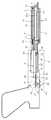
도 1은 본 발명의 일 실시예에 따른 수술용 스태플링 장문합장치를 개략적으로 나타내는 사시도이다. 수술용 스태플링 장문합장치는 절단문합유닛(10) 및 구동유닛(30), 그리고 절단문합유닛(10)과 구동유닛(30)의 사이에 위치하는 연결샤프트(20)를 포함한다.
1 is a perspective view schematically showing a surgical stapling anastomosis device according to an embodiment of the present invention. The surgical stapling anastomosis device includes a
절단문합유닛(10)은 상부죠(12) 및 하부죠(14)를 구비하며, 가위와 마찬가지로, 상부죠(12) 및 하부죠(14)는 상대적으로 회동하여 상부죠(12)와 하부죠(14)의 사이에 위치한 조직(tubular tissue)(예를 들어, 내장과 같은)을 클램핑한다. 하부죠(14)의 내부에는 문합 및 절단을 위한 쐐기(18)가 설치되며, 쐐기(18)는 이동을 통해 조직을 문합 및 절단한다.
The
구동유닛(30)은 핸들(32) 및 작동레버(36)를 구비하며, 시술자는 권총 손잡이 형상의 핸들(32)을 움켜쥐고 작동레버(36)를 조작하여 시술을 완료한다. 후술하는 바와 같이, 작동레버(36)는 핸들(32)의 상부에 설치되어 회전하며, 작동레버(36)의 회전력은 제1 및 제2 종동체(52,62)에 전달된다. 제1 종동체(52)의 회전을 통해 종동풀리(44)가 회전가능하며, 제2 종동체(62)의 회전을 통해 와이어(31)에 장력(tension)이 인가될 수 있다. 종동풀리(44)가 회전함에 따라, 상부죠(12) 및 하부죠(14)는 회전할 수 있으며, 와이어(31)에 장력이 인가됨에 따라, 쐐기(18)는 이동하여 조직을 문합 및 절단할 수 있다. 이에 대한 상세한 설명은 후술하기로 한다.
The
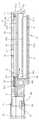
도 2는 도 1에 도시한 절단문합유닛에 대한 단면도이며, 도 3은 도 2에 도시한 상부죠의 단면도이다. 상부죠(12)의 근위부는 하부죠(14)의 근위부에 힌지를 통해 연결된다. 상부죠(12)는 힌지를 중심으로 회동에 의해 개방위치 및 폐쇄위치로 전환되며, 개방위치에서 상부죠(12)는 하부죠(14)와 기설정된 각도를 이루고, 폐쇄위치에서 상부죠(12)는 하부죠(14)의 상부에 하부죠(14)와 대체로 나란하게 놓여진다. 수술시, 시술자는 별도의 조작기구(도시안함)를 조작하여 상부죠(12)를 하부죠(14)에 대해 회동시키며, 상부죠(12)는 회동에 의해 하부죠(14)로부터 분리되어 초기 폐쇄위치에서 개방위치로 전환된다. 상부죠(12)가 개방위치로 전환되면, 시술자는 상부죠(12)와 하부죠(14) 사이에 내장의 개방 단부를 배치하며, 상부죠(12)를 하부죠(14)에 대해 반대로 회동시켜 상부죠(12)를 개방위치에서 폐쇄위치로 복귀시킨다. 이 과정에서 개방 단부는 상부죠(12)와 하부죠(14) 사이에서 클램핑될 수 있다.
2 is a cross-sectional view of the cutting anastomosis unit shown in Figure 1, Figure 3 is a cross-sectional view of the upper jaw shown in FIG. The proximal portion of the
도 2에 도시한 바와 같이, 하부죠(14)는 상부채널(15) 및 연결슬롯(16), 그리고 하부채널(17)을 가지며, 이들은 하부죠(14)의 길이방향을 따라 형성된다. 트레이(142)는 상부채널(15)의 상부에 설치되어 하부죠(14)로부터 분리가능하며, 초기에 복수의 스태플들(152)이 장전된다. 스태플들(152)은 상부채널(15)을 따라 이동하는 쐐기(wedge)(18)를 통해 작동하며, 작동시 폐쇄위치에 놓여진 상부죠(12)를 향해 이동한다.
As shown in FIG. 2, the
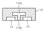
상부죠(12)는 트레이(142) 내의 스태플(152)에 대응되는 스태플 가이드(13)를 가지며, 스태플 가이드(13)는 상부죠(12)의 길이방향을 따라 배치된다. 트레이(142) 내의 스태플(152)은 스태플 가이드(13)를 향해 이동한 후 스태플 가이드(13)에 의해 만곡 변형되어 상부죠(12)와 하부죠(14)의 사이에 놓여진 조직의 개방 단부를 폐쇄한다. 앞서 설명한 바와 같이, 상부죠(12)가 개방된 상태로 전환된 경우 시술자는 상부죠(12)와 하부죠(14) 사이에 형성된 소정 공간을 통해 트레이(142)에 접근할 수 있으며, 트레이(142) 내에 장전된 스태플(152)을 확인하거나, 새로운 트레이(142)로 교체할 수 있다.
The
또한, 상부죠(12)는 상부슬롯(12a)을 가지며, 도 3에 도시한 바와 같이, 상부슬롯(12a)은 가이드슬롯(112a)과 이동슬롯(112b)을 가진다. 후술하는 가이드(18c)는 가이드슬롯(112a)을 따라 이동하며, 가이드(18c)는 가이드슬롯(112a)의 바닥면을 가압하여 상부죠(12)가 하부죠(14)로부터 이격되는 것을 방지한다. 조직이 상부죠(12)와 하부죠(14) 사이에 클램핑된 경우, 조직의 두께로 인해 상부죠(12)가 하부죠(14)로부터 이격될 수 있으며, 특히, 상부죠(12)의 원위 단부로 갈수록 이격거리는 증가한다. 따라서, 가이드(18c)를 이용하여 상부죠(12)를 가압하여 상부죠(12)의 이격을 방지할 수 있다. 상부슬롯(12a)은 근위부에 형성된 개구를 가지며, 상부죠(12)가 개방위치에서 폐쇄위치로 전환됨에 따라 가이드(18c)는 개구를 통해 가이드슬롯(112a) 내에 삽입될 수 있다. 후술하는 블레이드(18b)는 이동슬롯(112b)을 따라 이동한다.
In addition, the
쐐기(18)는 하부죠(14)의 내부에 설치되며, 쐐기(18)는 이동을 통해 조직을 스태플링 및 절단한다. 쐐기(18)는 상부채널(15)을 따라 이동하며, 경사면(18a) 및 블레이드(18b), 그리고 가이드(18c)를 구비한다. 경사면(18a)은 하부죠(14)의 근위 단부를 향하여 상향경사지도록 형성되며, 블레이드(18b)는 경사면(18a)의 상단으로부터 상부죠(12)를 향해 연장된다. 가이드(18c)는 블레이드(18b)의 상단부에 위치하며, 쐐기(18)가 이동함에 따라 가이드(18c)는 상부죠(12)에 형성된 가이드슬롯(12a)을 따라 이동한다.
The
스태플(152)은 트레이(142) 아래로 돌출된 기부와 트레이(142)의 상부를 향해 뻗어 있는 갈래를 구비한다. 쐐기(18)가 상부채널(15)을 따라 이동함에 따라, 블레이드(18b)는 조직을 절단하며, 쐐기(18)의 경사면(18a)은 스태플(152)의 기부를 가압한다. 스태플(152)의 갈래는 조직의 개방 단부를 통과하여 스태플 가이드(13)에 접촉하며, 스태플 가이드(13)는 스태플(152)을 만곡 성형하여 개방 단부를 폐쇄한다. 따라서, 조직의 개방 단부는 절단과 함께 폐쇄되며, 쐐기(18)가 상부채널(15)의 원위 단부까지 이동한 경우, 스태플들(152)은 모두 밀려서 트레이(142)를 통과하여 폐쇄 상태로 되며, 이를 통해 개방 단부가 문합된다. 이후, 쐐기(18)는 원래의 위치로 복귀한다.
The
와이어(31) 및 탄성체(50)는 하부채널(17) 내에 설치된다. 와이어(31)는 하부채널(17)의 원위부에 설치된 가이드풀리(42)에 감긴 상태를 유지하며, 와이어(31)의 일단은 쐐기(18)의 하부에 연결된 고정바(19)에 연결된다. 와이어(31)의 타단은 하부채널(17)의 근위부를 통해 연결샤프트(20)의 내부로 연장되며, 별도의 구동기구(도시안함)에 연결된다. 구동기구는 와이어(31)를 당겨 와이어(31)에 장력(tension)을 인가하며, 이를 통해 와이어(31)는 이동할 수 있다.
The
한편, 와이어(31)는 가이드풀리(42)를 기준으로 상부와이어(31a) 및 하부와이어(31c), 그리고 연결와이어(31b)로 구분될 수 있다. 상부와이어(31a)는 고정바(19)를 관통하며, 상부와이어(31a)의 좌측단은 연결와이어(31b)에 연결되고 상부와이어(31a)의 우측단은 하부채널(17)의 근위부를 통해 구동기구에 연결된다. 하부와이어(31c)의 좌측단은 연결와이어(31b)에 연결되며, 하부와이어(31c)의 우측단은 고정바(19)에 고정되어 고정바(19)와 함께 이동한다. 연결와이어(31b)는 가이드풀리(42)에 감겨진 부분을 의미하며, 상부와이어(31a) 및 하부와이어(31c)는 연결와이어(31b)를 통해 연결된다. 상부와이어(31a) 및 하부와이어(31c), 그리고 연결와이어(31b)는 설명의 편의를 위해 가이드풀리(42)를 기준으로 하는 위치에 따라 규정된 것이며, 와이어(31)가 이동함에 따라 와이어(31)의 특정 부분이 상부와이어(31a)나 하부와이어(31c) 또는 연결와이어(31b)가 될 수 있다.
Meanwhile, the
사이드풀리(41)는 하부채널(17)의 근위부에 설치되며, 와이어(31)의 측방향에 위치한다. 상부죠(12) 및 하부죠(14)가 연결샤프트(20)에 대하여 회동할 경우, 사이드풀리(41)는 와이어(31)의 측면을 지지하며, 와이어(31)가 이동함에 따라 사이드풀리(41)는 회전할 수 있다. 마찬가지로, 가이드풀리(42)는 와이어(31)의 이동에 의해 회전할 수 있다.
The
탄성체(50)의 일단은 고정바(19)에 연결되며, 탄성체(50)의 타단은 하부채널(17)의 근위부 측벽(17b)에 연결된다. 탄성체(50)는 고정바(19)를 기준으로 하부와이어(31c)의 반대편에 위치한다. 탄성체(50)는 인장스프링(tension spring)일 수 있으며, 와이어(31)에 장력이 인가됨에 따라 인장변형되고 와이어(31)에 인가된 장력이 제거됨에 따라 복원될 수 있다.
One end of the
도 4는 도 1의 A부분에 대한 확대도이며, 도 5는 도 4에 도시한 작동레버(36) 및 구동기어(39)를 나타내는 사시도이다. 앞서 설명한 바와 같이, 작동레버(36)는 핸들(32)의 상부에 위치한다. 또한, 도 5에 도시한 바와 같이, 작동레버(36)는 구동축(38)을 통해 구동기어(39)에 연결된다. 구동축(38)은 핸들(32)의 상부면을 관통하며, 작동레버(36)의 회전시 구동축(38)은 제3 회전중심(R3)을 기준으로 회동할 수 있다.
FIG. 4 is an enlarged view of a portion A of FIG. 1, and FIG. 5 is a perspective view of the operating
제1 종동체(52)는 핸들(32)의 내부에 실장되며, 원통 형상이다. 도 6은 도 4에 도시한 제1 종동기어(54) 및 구동풀리(56)를 나타내는 사시도이다. 제1 종동체(52)의 내주면에는 제1 종동기어(54)가 형성되며, 제1 종동기어(54)는 구동기어(39)와 맞물린 상태에서 구동기어(39)와 함께 회전한다. 구동기어(39)는 수기어 형상이며, 제1 종동기어(54)는 암기어 형상이다. 제1 종동체(52)는 구동풀리(56)에 연결되며, 구동풀리(56)는 제1 종동체(52)와 함께 회전한다.
The
조절판(34)은 핸들(32)의 내부에 고정설치된다. 도 7은 도 4에 도시한 조절판을 나타내는 도면이다. 조절판(34)은 제1 및 제2 관통홀(136,132)과 제1 및 제2 고정홀들(138,134)을 가진다. 제1 관통홀(136)은 제3 회전중심(R3) 상에 위치하며, 제1 고정홀들(138)은 제1 관통홀(136)(또는 제3 회전중심(R3))의 둘레에 위치한다. 제1 고정홀들(138)은 등각(θ, 예를 들어, 30°)을 이루도록 배치된다. 제2 관통홀(132)은 제2 회전중심(R2) 상에 위치하며, 제2 고정홀들(134)은 제2 관통홀(132)(또는 제2 회전중심(R2))의 둘레에 위치한다. 제2 고정홀들(134)은 등각(θ, 예를 들어, 30°)을 이루도록 배치된다.
The adjusting
제1 종동축(59)은 구동풀리(56)에 연결되며, 조절판(34)에 형성된 제1 관통홀(136)에 삽입되어 제1 관통홀(136) 내에서 구동풀리(56)와 함께 회전한다. 이때, 조절판(34)과 대향되는 구동풀리(56)의 일면에는 제1 스토퍼(58)가 형성되며, 제1 스토퍼(58)는 제1 고정홀들(138) 중 어느 하나에 선택적으로 삽입되어 구동풀리(56)의 회전을 제한할 수 있다. 예를 들어, 작동레버(36)의 회전시, 제1 스토퍼(58)는 구동풀리(56)와 함께 회전하여 제1 고정홀들(138)에 순차적으로 삽입되며, 시술자는 제1 스토퍼(58)가 이동한 제1 고정홀(138)의 개수를 파악함으로써 작동레버(36)의 회전각도를 즉시 알 수 있다. 또한, 시술자가 작동레버(36)를 조작하지 않는 경우, 제1 스토퍼(58)는 제1 고정홀(138)에 삽입되어 현재 작동레버(36)의 회전상태를 유지시킬 수 있으며, 이를 통해 작동레버(36)를 조작하지 않았음에도 불구하고 외력에 의해 구동풀리(56)가 회전하는 오동작을 방지할 수 있다.
The first driven
한편, 하부죠(14)의 근위부는 연결샤프트(20)의 원위부에 연결된다. 하부죠(14)는 상하에 연결된 회동축(45)을 통해 연결샤프트(20)에 연결되며, 회동축(45)은 제1 회전중심(R1) 상에 위치한다. 따라서, 하부죠(14)는 제1 회전중심(R1)을 기준으로 회동할 수 있다.
On the other hand, the proximal portion of the
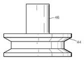
도 8은 도 4에 도시한 종동풀리를 나타내는 도면이다. 종동풀리(44)는 지지축(46)을 통해 하부죠(14)의 근위부에 고정설치되며, 종동풀리(44) 및 지지축(46)의 회전시 하부죠(14)는 함께 회동한다. 이때, 종동풀리(44) 및 지지축(46)은 제1 회전중심(R1)을 기준으로 회전하며, 하부죠(14)도 제1 회전중심(R1)을 기준으로 회동한다. 종동풀리(44)는 동력전달부재(예를 들어, 벨트와 같은)(B)를 통해 구동풀리(56)와 연결되며, 구동풀리(56)의 회전시 종동풀리(44)는 함께 회전한다. 이로 인해, 상부죠(12) 및 하부죠(14)는 회전할 수 있다.
8 is a view showing a driven pulley shown in FIG. The driven
도 9는 도 4에 도시한 동력전달부재의 단면을 나타내는 도면이다. 도 9에 도시한 바와 같이, 동력전달부재(B)는 내측의 길이(

9 is a view showing a cross section of the power transmission member shown in FIG. As shown in FIG. 9, the power transmission member B has an inner length (
도 10은 도 4에 도시한 작동레버를 통해 하부죠가 회동하는 모습을 나타내는 도면이다. 시술자는 상부죠(12) 및 하부죠(14)를 회동할 필요가 있는 경우, 도 10에 도시한 바와 같이, 시술자는 작동레버(36)를 이용하여 구동기어(39)를 제1 종동체(52)의 제1 종동기어(54)에 맞물린다. 이를 통해, 구동기어(39)는 제1 종동기어(54)와 분리된 상태('제1 해제위치')에서 제1 종동기어(54)와 맞물린 상태('제1 동작위치')로 전환되며, 제1 종동체(52)와 구동풀리(56)는 제1 동작위치에서 작동레버(36)의 회전을 통해 회전할 수 있다. 구동풀리(56)의 회전력은 동력전달부재(B)를 통해 종동풀리(44)에 전달되며, 이를 통해 종동풀리(44)와 상부죠(12) 및 하부죠(14)는 회동할 수 있다. 이때, 작동레버(36)의 회전방향과 상부죠(12) 및 하부죠(14)의 회동방향은 일치한다.
FIG. 10 is a view illustrating the lower jaw rotating through the operation lever shown in FIG. 4. When the operator needs to rotate the
한편, 앞서 설명한 바와 같이, 작동레버(36)의 회전시 제1 스토퍼(58)가 제1 고정홀들(138)에 순차적으로 삽입되므로, 시술자는 제1 스토퍼(58)가 이동한 제1 고정홀(138)의 개수를 통해 작동레버(36)의 회전각도를 알 수 있다.
Meanwhile, as described above, since the
도 11은 도 4에 도시한 제2 종동기어 및 보빈을 나타내는 사시도이다. 도 4에 도시한 바와 같이, 제2 종동체(62)는 핸들(32)의 내부에 실장되며, 원통 형상이다. 제2 종동체(62)의 내주면에는 제2 종동기어(63)가 형성되며, 제2 종동기어(63)는 구동기어(39)와 맞물린 상태에서 구동기어(39)와 함께 회전한다. 구동기어(39)는 수기어 형상이며, 제2 종동기어(63)는 암기어 형상이다. 원기둥 형상의 회전체(64)는 제2 종동체(62)의 하부에 연결되며, 보빈(68)은 회전체(64)의 하부에 연결된다. 제2 종동체(62)의 회전시 회전체(64) 및 보빈(68)은 함께 회전한다.
FIG. 11 is a perspective view illustrating the second driven gear and the bobbin illustrated in FIG. 4. As shown in FIG. 4, the
보빈(68)은 조절판(34)에 형성된 제2 관통홀(132)에 삽입되며, 제2 관통홀(132) 내에서 회전체(64)와 함께 회전한다. 보빈(68)은 와이어(31)가 고정되는 관통홀(68a)을 가지며, 와이어(31)는 관통홀(68a)에 삽입된 상태에서 매듭을 짓는 방법으로 보빈(68)에 고정될 수 있다. 따라서, 보빈(68)이 회전할 경우, 와이어(31)는 보빈(68)에 감겨 보빈(68)을 향해 당겨지므로, 와이어(31)에 장력이 인가될 수 있다.
The
한편, 조절판(34)과 대향되는 회전체(64)의 일면에는 제2 스토퍼(66)가 형성되며, 제2 스토퍼(66)는 제2 고정홀들(134) 중 어느 하나에 선택적으로 삽입되어 회전체(64)의 회전을 제한할 수 있다. 예를 들어, 작동레버(36)의 회전시, 제2 스토퍼(66)는 회전체(64)와 함께 회전하여 제2 고정홀들(134)에 순차적으로 삽입되며, 시술자는 제2 스토퍼(66)가 이동한 제2 고정홀(134)의 개수를 파악함으로써 작동레버(36)의 회전각도를 즉시 알 수 있다. 또한, 시술자가 작동레버(36)를 조작하지 않는 경우, 제2 스토퍼(66)는 제2 고정홀(134)에 삽입되어 현재 작동레버(36)의 회전상태를 유지시킬 수 있으며, 이를 통해 작동레버(36)를 조작하지 않았음에도 불구하고 외력에 의해 회전체(64)가 회전하는 오동작을 방지할 수 있다.
Meanwhile, a
도 12는 도 4에 도시한 작동레버를 통해 와이어가 이동하는 모습을 나타내는 도면이며, 도 13은 도 2에 도시한 쐐기의 동작을 나타내는 도면이다. 이하, 도 12 및 도 13을 참고하여 와이어 및 쐐기의 동작을 설명하기로 한다.
FIG. 12 is a view showing a state in which a wire moves through the operation lever shown in FIG. 4, and FIG. 13 is a view showing the operation of the wedge shown in FIG. 2. Hereinafter, the operation of the wire and the wedge will be described with reference to FIGS. 12 and 13.
먼저, 시술자는 상부죠(12)와 하부죠(14) 사이에 내장의 개방 단부를 배치하며, 상부죠(12)를 하부죠(14)에 대해 반대로 회동시켜 상부죠(12)를 개방위치에서 폐쇄위치로 복귀시킨다. 이 과정에서 개방 단부는 상부죠(12)와 하부죠(14) 사이에서 클램핑될 수 있으며, 이때, 쐐기(18)는 상부채널(15)의 근위부에 위치한다.
First, the operator places the open end of the viscera between the
이후, 도 12에 도시한 바와 같이, 시술자는 작동레버(36)를 이용하여 구동기어(39)를 제1 종동체(52)의 제1 종동기어(54)로부터 분리하여 제2 종동체(62)의 상부로 이동한 후, 제2 종동체(62)의 제2 종동기어(63)에 맞물릴 수 있다. 이를 통해, 구동기어(39)는 제2 종동기어(63)와 분리된 상태('제2 해제위치')에서 제2 종동기어(63)와 맞물린 상태('제2 동작위치')로 전환되며, 제2 종동체(62)와 보빈(68)은 제2 동작위치에서 작동레버(36)의 회전을 통해 회전할 수 있다. 보빈(68)이 회전시 와이어(31)는 보빈(68)에 감겨 보빈(68)을 향해 당겨지므로, 와이어(31)에 장력이 인가될 수 있다.
12, the operator separates the
이와 같은 방법으로 와이어(31)를 당기면, 도 13에 도시한 바와 같이, 상부와이어(31a)가 우측으로 이동하면서 가이드풀리(42)는 회전하며, 고정바(19)는 쐐기(18)와 함께 좌측(또는 상부채널(15)의 원위부측)으로 이동한다. 이때, 쐐기(18)가 이동함에 따라, 블레이드(18b)는 조직을 절단하며, 쐐기(18)의 경사면(18a)은 스태플(152)의 기부를 가압한다. 또한, 가이드(18c)는 가이드슬롯(112a)을 따라 이동하며, 가이드(18c)는 가이드슬롯(112a)의 바닥면을 가압하여 상부죠(12)가 하부죠(14)로부터 이격되는 것을 방지한다. 한편, 가이드풀리(42)는 하부채널(17)의 바닥면에 설치된 고정판(40)의 상부에 위치하며, 고정판(40)은 고정바(19)의 이동을 제한한다.
When the
상술한 바에 의하면, 작동레버(36)를 이용하여 와이어(31)에 장력을 인가할 수 있으며, 이를 통해 쐐기(18)를 구동하여 스태플링을 완료할 수 있다. 특히, 와이어(31)는 상부죠(12) 및 하부죠(14)가 연결샤프트에 대하여 회동한 경우에도 동력전달에 아무런 영향을 받지 않으며, 와이어(31)는 사이드풀리(41)에 의해 지지된 상태에서 쐐기(18)를 원활하게 구동할 수 있다. 따라서, 상부죠(12) 및 하부죠(14)의 회동과 관계 없이 스태플링 및 절단을 원활하게 진행할 수 있으며, 상부죠(12) 및 하부죠(14)가 구동방식에 의해 회동각도가 제한을 받지 않는다. 그러므로, 상부죠(12) 및 하부죠(14)가 충분한 회동변위를 확보할 수 있으며, 좁은 공간에서도 스태플링 및 절단을 원활하게 진행할 수 있다.
According to the above, the tension can be applied to the
한편, 도 13에 도시한 바와 같이, 고정바(19)가 좌측으로 이동함에 따라, 탄성체(50)는 인장변형된다. 시술자는 쐐기(18)의 이동을 통해 스태플링이 완료된 후, 작동레버(36)를 반대로 회전시킴으로써 와이어(31)에 인가된 장력을 제거할 수 있으며, 장력이 제거됨에 따라 고정바(19)는 탄성체(50)의 복원력에 의해 원래의 위치(도 2에 도시)로 복귀할 수 있다.
On the other hand, as shown in Figure 13, as the fixing
본 발명을 바람직한 실시예들을 통하여 상세하게 설명하였으나, 이와 다른 형태의 실시예들도 가능하다. 그러므로, 이하에 기재된 청구항들의 기술적 사상과 범위는 바람직한 실시예들에 한정되지 않는다.Although the present invention has been described in detail by way of preferred embodiments thereof, other forms of embodiment are possible. Therefore, the technical idea and scope of the claims set forth below are not limited to the preferred embodiments.
10 : 절단문합유닛12 : 상부죠
14 : 하부죠18 : 쐐기
19 : 연결바20 : 연결샤프트
30 : 구동유닛31 : 와이어
32 : 핸들34 : 조절판
36 : 작동레버39 : 구동기어
41 : 사이드풀리42 : 가이드풀리
44 : 종동풀리46 : 지지축
52 : 제1 종동체54 : 제1 종동기어
56 : 구동풀리58 : 제1 스토퍼
62 : 제2 종동체63 : 제2 종동기어
66 : 제2 스토퍼68 : 보빈10: cutting anastomosis unit 12: upper jaw
14: lower jaw 18: wedge
19: connecting bar 20: connecting shaft
30: drive unit 31: wire
32: handle 34: throttle
36: operating lever 39: drive gear
41: side pulley 42: guide pulley
44: driven pulley 46: support shaft
52: first driven body 54: first driven gear
56: drive pulley 58: first stopper
62: second driven gear 63: second driven gear
66: second stopper 68: bobbin
Claims (14)
Translated fromKorean상기 하부죠와 마주보는 상태로 대응되도록 배치되며, 상기 하부죠에 대하여 개방위치 및 폐쇄위치 사이에서 상대적으로 이동할 수 있는 상부죠(upper jaw);
상기 하부죠 및 상기 상부죠 중 어느 하나에 회동가능하도록 연결되는 연결샤프트;
상기 하부죠 및 상기 상부죠 중 어느 하나에 고정설치되며, 상기 연결샤프트에 대하여 상기 하부죠 및 상기 상부죠 중 어느 하나와 함께 회동하는 종동풀리;
상기 종동풀리에 동력을 제공하는 구동풀리;
상기 종동풀리와 상기 구동풀리를 연결하며, 상기 구동풀리의 동력을 상기 종동풀리에 전달하는 동력전달부재;
상기 구동풀리에 연결되어 상기 구동풀리와 함께 회전하며, 내주면에 제1 종동기어가 형성되는 원통 형상의 제1 종동체;
상기 제1 종동체에 삽입된 상태에서 상기 제1 종동기어에 맞물리는 구동기어; 및
상기 구동기어에 연결되어 상기 구동기어와 함께 회전하는 작동레버를 더 포함하는 것을 특징으로 하는 수술용 스태플링 장문합장치.Lower jaw;
An upper jaw disposed to face the lower jaw, the upper jaw being relatively movable between an open position and a closed position with respect to the lower jaw;
A connecting shaft rotatably connected to any one of the lower jaw and the upper jaw;
A driven pulley fixed to one of the lower jaw and the upper jaw and rotating together with any one of the lower jaw and the upper jaw with respect to the connection shaft;
A drive pulley for providing power to the driven pulley;
A power transmission member connecting the driven pulley and the driving pulley to transfer power of the driving pulley to the driven pulley;
A cylindrical first follower connected to the driving pulley to rotate together with the driving pulley and having a first driven gear formed on an inner circumferential surface thereof;
A drive gear engaged with the first driven gear in a state of being inserted into the first follower; And
And a working lever connected to the drive gear to rotate together with the drive gear.
상기 구동기어는 상하이동에 의해 상기 제1 종동기어와 맞물리는 제1 동작위치 및 상기 제1 종동기어로부터 분리되는 제1 해제위치로 전환되는 것을 특징으로 하는 수술용 스태플링 장문합장치.The method of claim 2,
And the drive gear is switched to a first operating position engaged with the first driven gear and a first release position separated from the first driven gear by a shanghaidong.
상기 하부죠와 마주보는 상태로 대응되도록 배치되며, 상기 하부죠에 대하여 개방위치 및 폐쇄위치 사이에서 상대적으로 이동할 수 있는 상부죠(upper jaw);
상기 하부죠 및 상기 상부죠 중 어느 하나에 회동가능하도록 연결되는 연결샤프트;
상기 하부죠 및 상기 상부죠 중 어느 하나에 고정설치되며, 상기 연결샤프트에 대하여 상기 하부죠 및 상기 상부죠 중 어느 하나와 함께 회동하는 종동풀리;
상기 종동풀리에 동력을 제공하는 구동풀리;
상기 종동풀리와 상기 구동풀리를 연결하며, 상기 구동풀리의 동력을 상기 종동풀리에 전달하는 동력전달부재;
상기 연결샤프트에 연결되는 핸들; 및
상기 핸들의 내부에 고정설치되어 상기 구동풀리의 일측에 위치하며, 상기 구동풀리의 회전중심 둘레에 배치된 복수의 제1 고정홀들을 가지는 조절판을 더 포함하며,
상기 구동풀리는 회전에 의해 상기 제1 고정홀들 중 어느 하나에 삽입되는 제1 스토퍼를 구비하는 것을 특징으로 하는 수술용 스태플링 장문합장치.Lower jaw;
An upper jaw disposed to face the lower jaw, the upper jaw being relatively movable between an open position and a closed position with respect to the lower jaw;
A connecting shaft rotatably connected to any one of the lower jaw and the upper jaw;
A driven pulley fixed to one of the lower jaw and the upper jaw and rotating together with any one of the lower jaw and the upper jaw with respect to the connection shaft;
A drive pulley for providing power to the driven pulley;
A power transmission member connecting the driven pulley and the driving pulley to transfer power of the driving pulley to the driven pulley;
A handle connected to the connection shaft; And
It is fixed to the inside of the handle is located on one side of the drive pulley, further comprising a control plate having a plurality of first fixing holes disposed around the rotation center of the drive pulley,
And the driving pulley has a first stopper inserted into one of the first fixing holes by rotation.
상기 하부죠와 마주보는 상태로 대응되도록 배치되며, 상기 하부죠에 대하여 개방위치 및 폐쇄위치 사이에서 상대적으로 이동할 수 있는 상부죠(upper jaw);
상기 하부죠 및 상기 상부죠 중 어느 하나에 회동가능하도록 연결되는 연결샤프트;
상기 하부죠 및 상기 상부죠 중 어느 하나에 고정설치되며, 상기 연결샤프트에 대하여 상기 하부죠 및 상기 상부죠 중 어느 하나와 함께 회동하는 종동풀리;
상기 종동풀리에 동력을 제공하는 구동풀리;
상기 종동풀리와 상기 구동풀리를 연결하며, 상기 구동풀리의 동력을 상기 종동풀리에 전달하는 동력전달부재;
초기에 상기 하부죠에 위치하여 상기 하부죠의 길이방향을 따라 위치하며, 상기 상부죠를 향해 이동하여 상기 하부죠와 상기 상부죠 사이에 위치한 조직(tissue)을 스태플링하는 하나 이상의 스태플;
상기 스태플의 아래에 배치되어 상기 하부죠의 길이방향을 따라 병진이동하며, 상기 스태플을 구동하는 쐐기(wedge);
상기 쐐기에 연결되며, 인가된 장력에 의해 상기 쐐기와 함께 이동하는 와이어; 및
상기 와이어가 연결되며, 회전에 의해 상기 와이어가 감기는 보빈을 더 포함하는 것을 특징으로 하는 수술용 스태플링 장문합장치.Lower jaw;
An upper jaw disposed to face the lower jaw, the upper jaw being relatively movable between an open position and a closed position with respect to the lower jaw;
A connecting shaft rotatably connected to any one of the lower jaw and the upper jaw;
A driven pulley fixed to one of the lower jaw and the upper jaw and rotating together with any one of the lower jaw and the upper jaw with respect to the connection shaft;
A drive pulley for providing power to the driven pulley;
A power transmission member connecting the driven pulley and the driving pulley to transfer power of the driving pulley to the driven pulley;
At least one staple initially positioned in the lower jaw and located along the longitudinal direction of the lower jaw, moving toward the upper jaw to staple tissue located between the lower jaw and the upper jaw;
A wedge disposed below the staple and translating along the longitudinal direction of the lower jaw to drive the staple;
A wire connected to the wedge and moving with the wedge by an applied tension; And
The stapling enteric device for surgery, characterized in that the wire is further connected, further comprising a bobbin wound by the wire by rotation.
상기 수술용 스태플링 장문합장치는,
상기 수술용 스태플링 장문합장치는,
초기에 상기 하부죠에 위치하여 상기 하부죠의 길이방향을 따라 위치하며, 상기 상부죠를 향해 이동하여 상기 하부죠와 상기 상부죠 사이에 위치한 조직(tissue)을 스태플링하는 하나 이상의 스태플;
상기 스태플의 아래에 배치되어 상기 하부죠의 길이방향을 따라 병진이동하며, 상기 스태플을 구동하는 쐐기(wedge);
상기 쐐기에 연결되며, 인가된 장력에 의해 상기 쐐기와 함께 이동하는 와이어;
상기 와이어가 연결되며, 회전에 의해 상기 와이어가 감기는 보빈;
상기 보빈에 연결되어 상기 보빈과 함께 회전하며, 내주면에 제2 종동기어가 형성되는 원통 형상의 제2 종동체를 더 포함하며,
상기 구동기어는 상하이동에 의해 상기 제2 종동기어와 맞물리는 제2 동작위치 및 상기 제2 종동기어로부터 분리되는 제2 해제위치로 전환되는 것을 특징으로 하는 수술용 스태플링 장문합장치.The method of claim 2,
The surgical stapling anastomosis device,
The surgical stapling anastomosis device,
At least one staple initially positioned in the lower jaw and located along the longitudinal direction of the lower jaw, moving toward the upper jaw to staple tissue located between the lower jaw and the upper jaw;
A wedge disposed below the staple and translating along the longitudinal direction of the lower jaw to drive the staple;
A wire connected to the wedge and moving with the wedge by an applied tension;
A bobbin to which the wire is connected and to which the wire is wound by rotation;
And a cylindrical second follower connected to the bobbin and rotating together with the bobbin, the second driven gear being formed on an inner circumferential surface thereof.
And the drive gear is switched to a second operating position engaged with the second driven gear and a second release position separated from the second driven gear by the shanghaidong.
상기 제1 종동기어와 상기 제2 종동기어는 동일한 형상인 것을 특징으로 하는 수술용 스태플링 장문합장치.The method according to claim 6,
And the first driven gear and the second driven gear have the same shape.
상기 수술용 스태플링 장문합장치는,
상기 연결샤프트에 연결되는 핸들;
상기 핸들의 내부에 고정설치되어 상기 보빈의 일측에 위치하며, 상기 보빈의 회전중심 둘레에 배치된 복수의 제2 고정홀들을 가지는 조절판; 및
상기 보빈에 연결되어 상기 보빈과 함께 회전하며, 회전에 의해 상기 제2 고정홀들 중 어느 하나에 삽입되는 제2 스토퍼를 구비하는 회전체를 더 포함하는 것을 특징으로 하는 수술용 스태플링 장문합장치.The method of claim 5,
The surgical stapling anastomosis device,
A handle connected to the connection shaft;
A control plate fixed to the inside of the handle and positioned at one side of the bobbin, the control plate having a plurality of second fixing holes disposed around a rotation center of the bobbin; And
A stapling surgical anastomosis device further comprising a rotating body connected to the bobbin to rotate together with the bobbin and having a second stopper inserted into one of the second fixing holes by rotation. .
상기 수술용 스태플링 장문합장치는 상기 쐐기에 연결되며 상기 장력에 의해 변형가능하고 상기 장력의 제거시 상기 쐐기와 함께 복원되는 탄성체를 더 포함하는 것을 특징으로 하는 수술용 스태플링 장문합장치.The method of claim 5,
The surgical stapling anastomosis device further comprises a elastic body connected to the wedge and deformable by the tension and restored with the wedge upon removal of the tension.
상기 수술용 스태플링 장문합장치는 상기 와이어가 감겨져 상기 와이어가 이동함에 따라 회전하는 가이드풀리를 더 포함하며,
상기 와이어는 상기 쐐기의 위치에 따라, 상기 쐐기를 관통하는 상부와이어 및 상기 상부와이어의 하부에 위치하여 일단이 상기 쐐기에 고정되는 하부와이어, 그리고 상기 상부와이어와 상기 하부와이어를 연결하며 상기 가이드풀리에 감겨진 연결와이어를 구비하는 것을 특징으로 하는 수술용 스태플링 장문합장치.10. The method according to claim 5 or 9,
The surgical stapling enteric anastomosis device further comprises a guide pulley that is rotated as the wire is wound and the wire is moved,
According to the position of the wedge, the upper wire passing through the wedge and the lower wire which is positioned below the upper wire and one end is fixed to the wedge, and connects the upper wire and the lower wire and the guide pulley Surgical stapling anastomosis device characterized in that it comprises a connection wire wound on.
상기 수술용 스태플링 장문합장치는 상기 와이어가 감겨져 상기 와이어가 이동함에 따라 회전하는 가이드풀리를 더 포함하며,
상기 와이어는 상기 쐐기의 위치에 따라, 상기 쐐기를 관통하는 상부와이어 및 상기 상부와이어의 하부에 위치하여 일단이 상기 쐐기에 고정되는 하부와이어, 그리고 상기 상부와이어와 상기 하부와이어를 연결하며 상기 가이드풀리에 감겨진 연결와이어를 구비하되,
상기 탄성체는 상기 쐐기를 기준으로 상기 하부와이어의 반대편에 위치하는 것을 특징으로 하는 수술용 스태플링 장문합장치.10. The method of claim 9,
The surgical stapling enteric anastomosis device further comprises a guide pulley that is rotated as the wire is wound and the wire is moved,
According to the position of the wedge, the upper wire passing through the wedge and the lower wire which is positioned below the upper wire and one end is fixed to the wedge, and connects the upper wire and the lower wire and the guide pulley With a connecting wire wound on
And the elastic body is positioned on the opposite side of the lower wire with respect to the wedge.
상기 가이드풀리는 상기 하부죠의 원위부에 위치하며,
상기 탄성체의 일단은 상기 하부죠의 근위부에 고정되는 것을 특징으로 하는 수술용 스태플링 장문합장치.The method of claim 10,
The guide pulley is located distal to the lower jaw,
One end of the elastic body is a surgical stapling anastomosis device, characterized in that fixed to the proximal portion of the lower jaw.
상기 상부와이어의 이동방향과 상기 쐐기의 이동방향은 반대인 것을 특징으로 하는 수술용 스태플링 장문합장치.The method of claim 10,
Surgical stapling enteric anastomosis device characterized in that the movement direction of the upper wire and the movement direction of the wedge is opposite.
상기 상부죠의 근위부는 상기 하부죠의 근위부에 회동가능하도록 연결되고,
상기 쐐기는 상기 하부죠의 근위부를 향하여 상향경사진 경사면을 구비하며,
상기 장력에 의해 상기 하부죠의 원위부를 향해 이동하는 것을 특징으로 하는 수술용 스태플링 장문합장치.10. The method according to claim 5 or 9,
The proximal portion of the upper jaw is rotatably connected to the proximal portion of the lower jaw,
The wedge has a slope inclined upward toward the proximal portion of the lower jaw,
Surgical stapling anastomosis device characterized in that it moves toward the distal portion of the lower jaw by the tension.
Priority Applications (1)
| Application Number | Priority Date | Filing Date | Title |
|---|---|---|---|
| KR1020110094669AKR101286281B1 (en) | 2011-09-20 | 2011-09-20 | Belt drive type surgical stapling enteroanastomotic device |
Applications Claiming Priority (1)
| Application Number | Priority Date | Filing Date | Title |
|---|---|---|---|
| KR1020110094669AKR101286281B1 (en) | 2011-09-20 | 2011-09-20 | Belt drive type surgical stapling enteroanastomotic device |
Publications (2)
| Publication Number | Publication Date |
|---|---|
| KR20130031019A KR20130031019A (en) | 2013-03-28 |
| KR101286281B1true KR101286281B1 (en) | 2013-07-15 |
Family
ID=48180399
Family Applications (1)
| Application Number | Title | Priority Date | Filing Date |
|---|---|---|---|
| KR1020110094669AExpired - Fee RelatedKR101286281B1 (en) | 2011-09-20 | 2011-09-20 | Belt drive type surgical stapling enteroanastomotic device |
Country Status (1)
| Country | Link |
|---|---|
| KR (1) | KR101286281B1 (en) |
Families Citing this family (1)
| Publication number | Priority date | Publication date | Assignee | Title |
|---|---|---|---|---|
| CN113243955B (en)* | 2021-06-18 | 2022-05-03 | 苏州优脉瑞医疗科技有限公司 | Anastomat capable of accurately positioning angle of nail bin |
Citations (4)
| Publication number | Priority date | Publication date | Assignee | Title |
|---|---|---|---|---|
| JPH08289895A (en)* | 1995-04-21 | 1996-11-05 | Olympus Optical Co Ltd | Suture device |
| JP2005342267A (en) | 2004-06-03 | 2005-12-15 | Olympus Medical Systems Corp | Surgical instrument |
| JP2010012264A (en)* | 2008-07-01 | 2010-01-21 | Tyco Healthcare Group Lp | Retraction mechanism with clutch-less drive for use with surgical apparatus |
| US7861907B2 (en) | 1991-10-18 | 2011-01-04 | Tyco Healthcare Group Lp | Surgical stapling apparatus |
- 2011
- 2011-09-20KRKR1020110094669Apatent/KR101286281B1/ennot_activeExpired - Fee Related
Patent Citations (4)
| Publication number | Priority date | Publication date | Assignee | Title |
|---|---|---|---|---|
| US7861907B2 (en) | 1991-10-18 | 2011-01-04 | Tyco Healthcare Group Lp | Surgical stapling apparatus |
| JPH08289895A (en)* | 1995-04-21 | 1996-11-05 | Olympus Optical Co Ltd | Suture device |
| JP2005342267A (en) | 2004-06-03 | 2005-12-15 | Olympus Medical Systems Corp | Surgical instrument |
| JP2010012264A (en)* | 2008-07-01 | 2010-01-21 | Tyco Healthcare Group Lp | Retraction mechanism with clutch-less drive for use with surgical apparatus |
Also Published As
| Publication number | Publication date |
|---|---|
| KR20130031019A (en) | 2013-03-28 |
Similar Documents
| Publication | Publication Date | Title |
|---|---|---|
| JP6389007B2 (en) | Staple cartridge unit and medical stapler using the staple cartridge unit | |
| CN100569190C (en) | Surgical Suture Instruments | |
| US5653374A (en) | Self-contained powered surgical apparatus | |
| EP2243433B1 (en) | Self-contained powered surgical apparatus | |
| US20160317172A1 (en) | Tissue excision device | |
| EP3087928A1 (en) | Treatment tool handle and treatment tool | |
| EP2286737A1 (en) | One handed stapler | |
| EP3165177A1 (en) | Single-trigger clamping and firing of surgical stapler | |
| EP1982657A2 (en) | Flexible endoluminal surgical instrument | |
| JPWO2013073523A1 (en) | Medical equipment | |
| EP2943133A1 (en) | Low profile medical device and related methods of use | |
| CN112739274A (en) | Articulating Blade Deployment | |
| KR101286281B1 (en) | Belt drive type surgical stapling enteroanastomotic device | |
| US9320519B1 (en) | Single-trigger clamping and firing of surgical stapler | |
| KR102143102B1 (en) | Linear Stapler | |
| KR20250083814A (en) | End tool and surgical instrument | |
| KR101111213B1 (en) | Gear and cam type anastomosis device | |
| WO2016199258A1 (en) | Medical stapler | |
| KR101334203B1 (en) | Wire drive type surgical stapling enteroanastomotic device | |
| KR102729812B1 (en) | End tool, cartridge, surgical instrument and operation method of surgical instrument | |
| US20250160830A1 (en) | Cartridge for surgical instrument and surgical instrument including the cartridge | |
| KR101584064B1 (en) | Anastomosis apparatus | |
| EP1832237B1 (en) | Ligature and suture device for medical application | |
| KR20250038550A (en) | End tool, cartridge, surgical instrument and operation method of surgical instrument | |
| KR20070108134A (en) | Surgical stapling instruments |
Legal Events
| Date | Code | Title | Description |
|---|---|---|---|
| A201 | Request for examination | ||
| PA0109 | Patent application | St.27 status event code:A-0-1-A10-A12-nap-PA0109 | |
| PA0201 | Request for examination | St.27 status event code:A-1-2-D10-D11-exm-PA0201 | |
| D13-X000 | Search requested | St.27 status event code:A-1-2-D10-D13-srh-X000 | |
| D14-X000 | Search report completed | St.27 status event code:A-1-2-D10-D14-srh-X000 | |
| E902 | Notification of reason for refusal | ||
| PE0902 | Notice of grounds for rejection | St.27 status event code:A-1-2-D10-D21-exm-PE0902 | |
| E13-X000 | Pre-grant limitation requested | St.27 status event code:A-2-3-E10-E13-lim-X000 | |
| P11-X000 | Amendment of application requested | St.27 status event code:A-2-2-P10-P11-nap-X000 | |
| P13-X000 | Application amended | St.27 status event code:A-2-2-P10-P13-nap-X000 | |
| PG1501 | Laying open of application | St.27 status event code:A-1-1-Q10-Q12-nap-PG1501 | |
| E701 | Decision to grant or registration of patent right | ||
| PE0701 | Decision of registration | St.27 status event code:A-1-2-D10-D22-exm-PE0701 | |
| GRNT | Written decision to grant | ||
| PR0701 | Registration of establishment | St.27 status event code:A-2-4-F10-F11-exm-PR0701 | |
| PR1002 | Payment of registration fee | St.27 status event code:A-2-2-U10-U11-oth-PR1002 Fee payment year number:1 | |
| PG1601 | Publication of registration | St.27 status event code:A-4-4-Q10-Q13-nap-PG1601 | |
| LAPS | Lapse due to unpaid annual fee | ||
| PC1903 | Unpaid annual fee | St.27 status event code:A-4-4-U10-U13-oth-PC1903 Not in force date:20160710 Payment event data comment text:Termination Category : DEFAULT_OF_REGISTRATION_FEE | |
| PC1903 | Unpaid annual fee | St.27 status event code:N-4-6-H10-H13-oth-PC1903 Ip right cessation event data comment text:Termination Category : DEFAULT_OF_REGISTRATION_FEE Not in force date:20160710 | |
| P22-X000 | Classification modified | St.27 status event code:A-4-4-P10-P22-nap-X000 |