KR101286070B1 - Prosthesis of intervertebral disc for cervical spine - Google Patents
Prosthesis of intervertebral disc for cervical spineDownload PDFInfo
- Publication number
- KR101286070B1 KR101286070B1KR1020120017921AKR20120017921AKR101286070B1KR 101286070 B1KR101286070 B1KR 101286070B1KR 1020120017921 AKR1020120017921 AKR 1020120017921AKR 20120017921 AKR20120017921 AKR 20120017921AKR 101286070 B1KR101286070 B1KR 101286070B1
- Authority
- KR
- South Korea
- Prior art keywords
- disc
- artificial
- cervical
- artificial disc
- disc member
- Prior art date
- Legal status (The legal status is an assumption and is not a legal conclusion. Google has not performed a legal analysis and makes no representation as to the accuracy of the status listed.)
- Active
Links
Images


Classifications
- A—HUMAN NECESSITIES
- A61—MEDICAL OR VETERINARY SCIENCE; HYGIENE
- A61F—FILTERS IMPLANTABLE INTO BLOOD VESSELS; PROSTHESES; DEVICES PROVIDING PATENCY TO, OR PREVENTING COLLAPSING OF, TUBULAR STRUCTURES OF THE BODY, e.g. STENTS; ORTHOPAEDIC, NURSING OR CONTRACEPTIVE DEVICES; FOMENTATION; TREATMENT OR PROTECTION OF EYES OR EARS; BANDAGES, DRESSINGS OR ABSORBENT PADS; FIRST-AID KITS
- A61F2/00—Filters implantable into blood vessels; Prostheses, i.e. artificial substitutes or replacements for parts of the body; Appliances for connecting them with the body; Devices providing patency to, or preventing collapsing of, tubular structures of the body, e.g. stents
- A61F2/02—Prostheses implantable into the body
- A61F2/30—Joints
- A61F2/44—Joints for the spine, e.g. vertebrae, spinal discs
- A—HUMAN NECESSITIES
- A61—MEDICAL OR VETERINARY SCIENCE; HYGIENE
- A61B—DIAGNOSIS; SURGERY; IDENTIFICATION
- A61B17/00—Surgical instruments, devices or methods
- A61B17/56—Surgical instruments or methods for treatment of bones or joints; Devices specially adapted therefor
- A61B17/58—Surgical instruments or methods for treatment of bones or joints; Devices specially adapted therefor for osteosynthesis, e.g. bone plates, screws or setting implements
- A61B17/68—Internal fixation devices, including fasteners and spinal fixators, even if a part thereof projects from the skin
- A61B17/70—Spinal positioners or stabilisers, e.g. stabilisers comprising fluid filler in an implant
- A—HUMAN NECESSITIES
- A61—MEDICAL OR VETERINARY SCIENCE; HYGIENE
- A61F—FILTERS IMPLANTABLE INTO BLOOD VESSELS; PROSTHESES; DEVICES PROVIDING PATENCY TO, OR PREVENTING COLLAPSING OF, TUBULAR STRUCTURES OF THE BODY, e.g. STENTS; ORTHOPAEDIC, NURSING OR CONTRACEPTIVE DEVICES; FOMENTATION; TREATMENT OR PROTECTION OF EYES OR EARS; BANDAGES, DRESSINGS OR ABSORBENT PADS; FIRST-AID KITS
- A61F2/00—Filters implantable into blood vessels; Prostheses, i.e. artificial substitutes or replacements for parts of the body; Appliances for connecting them with the body; Devices providing patency to, or preventing collapsing of, tubular structures of the body, e.g. stents
- A61F2/02—Prostheses implantable into the body
- A61F2/28—Bones
- A—HUMAN NECESSITIES
- A61—MEDICAL OR VETERINARY SCIENCE; HYGIENE
- A61F—FILTERS IMPLANTABLE INTO BLOOD VESSELS; PROSTHESES; DEVICES PROVIDING PATENCY TO, OR PREVENTING COLLAPSING OF, TUBULAR STRUCTURES OF THE BODY, e.g. STENTS; ORTHOPAEDIC, NURSING OR CONTRACEPTIVE DEVICES; FOMENTATION; TREATMENT OR PROTECTION OF EYES OR EARS; BANDAGES, DRESSINGS OR ABSORBENT PADS; FIRST-AID KITS
- A61F2/00—Filters implantable into blood vessels; Prostheses, i.e. artificial substitutes or replacements for parts of the body; Appliances for connecting them with the body; Devices providing patency to, or preventing collapsing of, tubular structures of the body, e.g. stents
- A61F2/02—Prostheses implantable into the body
- A61F2/30—Joints
- A61F2002/30001—Additional features of subject-matter classified in A61F2/28, A61F2/30 and subgroups thereof
Landscapes
- Health & Medical Sciences (AREA)
- Orthopedic Medicine & Surgery (AREA)
- Engineering & Computer Science (AREA)
- Biomedical Technology (AREA)
- Life Sciences & Earth Sciences (AREA)
- Animal Behavior & Ethology (AREA)
- General Health & Medical Sciences (AREA)
- Heart & Thoracic Surgery (AREA)
- Neurology (AREA)
- Veterinary Medicine (AREA)
- Public Health (AREA)
- Oral & Maxillofacial Surgery (AREA)
- Cardiology (AREA)
- Transplantation (AREA)
- Vascular Medicine (AREA)
- Surgery (AREA)
- Nuclear Medicine, Radiotherapy & Molecular Imaging (AREA)
- Medical Informatics (AREA)
- Molecular Biology (AREA)
- Prostheses (AREA)
- Surgical Instruments (AREA)
Abstract
Translated fromKoreanDescription
Translated fromKorean본 발명은 경추용 인공 디스크에 관한 것으로, 더 상세하게는 목 디스크 수술 시 수술 편의성을 향상시키고, 수술 후 목의 움직임이 원활하게 하는 경추용 인공 디스크에 관한 것이다.The present invention relates to an artificial disc for cervical vertebra, and more particularly, to an artificial disc for cervical vertebrae which improves the operability of the neck disc surgery and smoothes the movement of the neck after surgery.
일반적으로, 척추는 경추(목뼈), 흉추(등뼈), 요추(허리뼈), 천추(골반뼈), 미추(꼬리뼈)를 포함하며, 경추 7개, 흉추 12개, 요추 5개, 천추 5개, 미추 4개로 총 33개의 척추뼈로 구성된다.Generally, the vertebrae include cervical spine, thoracic spine, lumbar spine, sacrum (pelvic bone), and spine (tail bone), including seven cervical vertebrae, twelve thoracic vertebrae, five lumbar vertebrae, five vertebrae , And a total of 33 vertebrae.
상기 경추와, 흉추, 요추의 각각의 척추뼈 사이에는 뼈 사이의 추간 원판이 있고, 상기 추간 원판은 두꺼운 원반 형상으로 탄성이 풍부한 섬유 연골로 되어 있으며, 수핵을 섬유륜이 감싸는 형태를 가진다.An intervertebral disc between bones is provided between the vertebrae of each of the cervical vertebrae, thoracic vertebra, and lumbar vertebra. The intervertebral disc has a thick disc shape and is made of elastic fibrous cartilage.
상기 추간 원판은 노화에 의해 손상되거나, 잘못된 자세가 반복되거나 오래 앉아 있는 경우 손상되기 쉽고, 무거운 중량의 물건을 들다가 손상되기 쉽다.The intervertebral disc is liable to be damaged if it is damaged by aging, is repeated in a wrong posture or is sitting for a long time, and is liable to be damaged by holding a heavy object.
상기 추간 원판이 손상되는 경우 추간 원판이 뼈와 뼈 사이에서 이탈하거나, 디스크 안의 수핵이 빠져 나와 척추의 신경을 자극하여 통증을 유발하며 심한 경우 마비까지 발생한다.If the intervertebral disc is damaged, the intervertebral disc may be separated between the bones and bone, or the disc nucleus may escape to stimulate the nerves of the spinal column to cause pain, and severe cases may result in paralysis.
상기한 바와 같이 추간 원판이 손상된 경우 환자의 환부를 절개하고 섬유륜 밖으로 밀려나간 수핵을 제거하는 디스크 수핵 절제 수술 또는 손상된 추간 원판을 제거한 후 인공 추간 원판을 삽입하는 디스크 치환 수술로 치료하고 있다.As described above, when the intervertebral disc is damaged, the patient is treated with a disc nucleusectomy to remove the nucleus pushed out of the femur, or a disc replacement operation in which a damaged intervertebral disc is removed and an artificial intervertebral disc is inserted.
한편, 도 1을 참고하면, 경추용 인공 추간 원판은 두 개의 경추(1) 사이에 삽입되는 원판 삽입물(2)과, 상기 원판 삽입물(2)이 삽입되는 경추 중 상부 경추의 하부면에 장착되는 상부 고정체(3)와, 상기 원판 삽입물(2)이 삽입되는 경추 중 하부 경추의 상부면에 장착되는 하부 고정체(4)를 포함한다.1, the artificial intervertebral disc for cervical vertebrae comprises a disc insert 2 inserted between two
그러나, 상기 경추용 인공 추간 원판은 상부 고정체(3)와 하부 고정체(4)를 각각 경추의 하부면과, 경추의 상부면에 각각 고정시켜야 하므로, 수술 과정이 복잡하고 어려운 문제점이 있었던 것이다.However, since the cervical artificial intervertebral disc requires fixing the upper fixture 3 and the lower fixture 4 to the lower surface of the cervical vertebrae and the upper surface of the cervical vertebrae respectively, the operation procedure is complicated and difficult .
또한, 상기 경추용 인공 추간 원판은 수술 후 장기간 사용 중 상부 고정체(3)와 하부 고정체(4)의 사이에서 원판 삽입물(2)이 이탈되는 사고가 자주 발생되며, 목의 움직임이 원활하지 못하는 문제점이 있었던 것이다.In addition, the cervical spine artificial intervertebral disc frequently has an accident that the disc insert 2 is detached between the upper fixture 3 and the lower fixture 4 during long-term use after surgery, and the movement of the neck is smooth There was a problem that could not be done.
본 발명과 관련 선행 기술로는 국내 공개특허 제10-2008-0007238호(2008.01.17공개, 척추 디스크 인공 보형물)이 있다.The present invention and related prior art are disclosed in Korean Patent Laid-Open No. 10-2008-0007238 (published on Jan. 17, 2008, a spinal disc prosthesis).
본 발명의 목적은 디스크 치환 수술 시 수술 편의성을 향상시키고, 수술 후 목의 움직임이 원활하고, 장기간 안정적인 사용이 가능한 경추용 인공 추간 원판을 제공하는 데 있다.An object of the present invention is to provide an artificial intervertebral disc for cervical vertebrae which improves the operability at the time of disc replacement surgery, smoothly moves the neck after surgery, and can be used stably for a long period of time.
이러한 본 발명의 과제는 경추 사이에 삽입되는 인공 디스크부재; 및An object of the present invention is to provide an artificial disc member inserted between cervical vertebrae; And
상기 인공 디스크부재가 경추 사이에 위치되게 상기 인공 디스크부재를 지지하며 경추에 장착되는 디스크 지지부재를 포함하며,And a disc supporting member mounted on the cervical spine supporting the artificial disc member such that the artificial disc member is positioned between the cervical vertebrae,
상기 인공 디스크부재는 정면과 양측면으로 개방된 슬릿 홈부가 형성된 경추용 인공 추간 원판을 제공함으로써 해결된다.The artificial disc member is solved by providing an artificial intervertebral disc for cervical vertebra having a slit groove portion opened to the front side and both side surfaces.
본 발명에 따른 경추용 인공 추간 원판은 수술 후 목을 원활하고, 자연스럽게 움직일 수 있게 하고, 장기간 안정적으로 사용이 가능하여 환자의 만족도를 크게 향상시키는 효과가 있다.INDUSTRIAL APPLICABILITY The artificial intervertebral disc for cervical spine according to the present invention can smoothly and naturally move the neck after surgery and can be used stably for a long period of time, thereby greatly improving the patient's satisfaction.
본 발명에 따른 경추용 인공 추간 원판은 수술을 간편하게 할 수 있게 하여 수술 시간을 단축시키고, 수술의 정확도를 향상시키는 효과가 있다.The artificial intervertebral disc for cervical spine according to the present invention can simplify the operation, shorten the operation time, and improve the accuracy of the operation.
도 1은 종래의 경추용 인공 추간 원판을 도시한 단면도
도 2는 본 발명에 따른 경추용 인공 추간 원판을 도시한 사시도
도 3 내지 도 4는 본 발명에 따른 경추용 인공 추간 원판의 사용 상태를 도시한 사시도
도 5는 본 발명에 따른 경추용 인공 추간 원판의 사용 상태를 도시한 단면도1 is a cross-sectional view of a conventional artificial intervertebral disc for cervical vertebra
FIG. 2 is a perspective view of a cervical spine artificial intervertebral disc according to the present invention. FIG.
Figs. 3 to 4 are perspective views showing the state of use of the cervical spine artificial intervertebral disc according to the present invention. Fig.
FIG. 5 is a sectional view showing the state of use of the artificial intervertebral disc for cervical vertebrae according to the present invention
본 발명의 바람직한 실시 예를 첨부된 도면에 의하여 상세히 설명하면 다음과 같다.DETAILED DESCRIPTION OF THE PREFERRED EMBODIMENTS Hereinafter, preferred embodiments of the present invention will be described in detail with reference to the accompanying drawings.
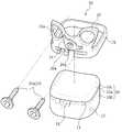
도 2 내지 도 4를 참고하면, 본 발명에 따른 경추용 인공 추간 원판은 경추(1) 사이에 삽입되는 인공 디스크부재(10)를 포함한다.2 to 4, the cervical spine artificial intervertebral disc according to the present invention includes an
상기 인공 디스크부재(10)는 PEEK(Polyetherethereketone)인 것을 일 예로 하며, 이외에도 폴리머 재질 또는 금속(metal) 재질로 다양하게 변형 실시될 수 있음을 밝혀둔다. 상기 인공 디스크부재(10)는 외측 둘레 및 각 모서리가 둥글게 형성되어 경추(1) 사이에서 움직임이 원활하고, 경추(1)와의 접촉 시 경추(1)를 손상시키지 않도록 한다. 또한, 상기 인공 디스크부재(10)의 내부에는 수술 후 X레이 촬영 시 상기 인공 디스크부재(10)의 위치를 확인할 수 있게 하는 위치 인식 핀(12)이 삽입된다. 상기 위치 인식 핀(12)은 금속재로 형성되고, 상기 인공 디스크부재(10)에 형성된 복수의 장착홈 내부에 삽입되어 장착되는 것을 일 예로 한다.The
상기 인공 디스크부재(10)는 상부면에 둥글게 파여진 홈부가 형성되고, 하부면이 둥글게 돌출되는 형상으로 형성되어 경추(1)의 사이에서 경추(1)의 하부면과, 경추(1)의 상부면에 지지되어 원활하게 움직일 수 있는 형상을 가지는 것이 바람직하다.The
또한, 상기 인공 디스크부재(10)는 정면과 양 측면으로 개방된 슬릿 홈부(11)가 형성된다. 상기 인공 디스크부재(10)는 정면과 양 측면으로 개방된 슬릿 홈부(11)가 형성되어 'ㄷ'자 형상의 단면을 가진다. 더 상세하게 설명하면, 상기 인공 디스크부재(10)는 상부에 배치된 경추(1)의 하부면에 지지되는 상부 디스크부(10a);In addition, the
상기 상부 디스크부(10a)와 이격되어 사이에 상기 슬릿 홈부(11)를 형성하고, 하부에 배치된 경추(1)의 상부면에 지지되는 하부 디스크부(10b); 및A
상기 상부 디스크부(10a)와 상기 하부 디스크의 일 측에서 상기 상부 디스크부(10a)와 상기 하부 디스크부(10b)를 일체로 연결하는 연결 디스크부(10c)를 포함한다.And a
상기 인공 디스크부재(10)는 상기 슬릿 홈부(11)에 의해 충격을 완충시키는 작용을 한다. 즉, 상기 인공 디스크부재(10)는 상기 상부 디스크부(10a)와 상기 하부 디스크부(10b) 사이에 슬릿 홈부(11)가 형성되어 상기 연결 디스크부(10c)를 중심으로 탄성을 가지게 되어 경추(1) 사이에서 머리를 지지하고, 목을 움직일 때 발생되는 충격을 흡수한다.The
상기 인공 디스크부재(10)는 경추(1) 사이에서 머리를 지지하고, 목을 움직일 때 발생되는 충격을 흡수하여 목의 움직임을 원활하게 하고, 목을 더 자연스럽게 움직일 수 있게 하며 사용 중 마모에 의한 손상이 최소화되어 수명도 긴 효과가 있다.The
또한, 본 발명에 따른 경추용 인공 추간 원판은 상기 인공 디스크부재(10)를 경추(1) 사이에 위치되게 지지하는 디스크 지지부재(20)를 포함한다.In addition, the cervical spine artificial intervertebral disc according to the present invention includes a
상기 디스크 지지부재(20)는 경추(1)에 장착되어 고정된다. 상기 디스크 지지부재(20)는 링 형상으로 형성되어 내부에 상기 인공 디스크부재(10)가 배치되는 링 몸체부(21)와;The
상기 링 몸체부(21)의 전면에서 경추(1)에 장착되며, 장착 구멍(22a)이 형성된 몸체 장착부(22)를 포함한다.And a
상기 디스크 지지부재(20)는 상기 몸체 장착부(22)의 장착 구멍(22a)을 관통하여 상기 경추(1)에 장착되는 몸체 고정부(23)를 더 포함한다.The
상기 몸체 장착부(22)는 상기 링 몸체부(21)의 상부 또는 하부로 돌출되게 상기 링 몸체부(21)에 일체로 형성되며, 경추(1)에 겹쳐져 경추(1)의 일부분을 감싸는 형상으로 형성된다. 상기 몸체 고정부(23)는 경추(1)에 체결되는 고정 스크류(23a)인 것을 일 예로 한다.The
상기 인공 디스크부재(10)는 링 형상으로 형성된 상기 링 몸체부(21)의 내부에 삽입되어 경추(1) 사이에서 이탈되지 않게 된다. 즉, 상기 링 몸체부(21)가 상기 인공 디스크부재(10)를 감싸 상기 인공 디스크부재(10)가 경추(1) 사이에 위치되게 지지하며, 경추(1) 사이에서 인공 디스크부재(10)가 이탈되는 것을 방지한다.The
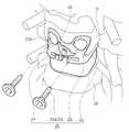
상기 디스크 지지부재(20)는 상기 몸체 장착부(22)에 구비되며 상기 장착 구멍(22a)을 통해 경추(1)에 체결된 상기 고정 스크류(23a)의 머리부분에 걸리는 머리 걸림부(24)를 더 포함한다.The
상기 머리 걸림부(24)는 상기 몸체 장착부(22)에 회전 가능하게 장착되고, 공구가 삽입되는 공구 삽입홈(24a)이 전면에 형성되어 상기 공구 삽입홈(24a)에 삽입된 공구에 의해 회전된다. 상기 머리 걸림부(24)는 상기 고정 스크류(23a)가 상기 장착 구멍(22a)을 통과하여 경추(1)에 체결된 후 회전되어 상기 장착 구멍(22a)을 통해 체결된 상기 고정 스크류(23a)의 머리를 걸도록 위치된다. 상기 고정 스크류(23a)는 상기 머리 걸림부(24)에 걸려 수술 후 목의 움직임에 의해 풀리는 것이 방지되고, 체결된 상태가 견고하게 유지된다.The
또한, 상기 인공 디스크부재(10)는 전면에 수술 도구(5)가 삽입될 수 있는 도구 삽입홈(13)이 형성되고, 상기 디스크 지지부재(20)는 상기 링 몸체부(21)의 전면에 상기 도구 삽입홈(13)에 대응되는 도구 관통 구멍(20a)이 형성되는 것이 바람직하다.The
상기 도구 삽입홈(13)과 상기 도구 관통 구멍(20a)은 상기 인공 디스크부재(10)가 상기 링 몸체부(21) 내에서 수술 시 정해진 위치로 배치될 수 있게 형성된다.The
즉, 상기 도구 관통 구멍(20a)을 통해 수술 도구(5)를 상기 도구 삽입홈(13)에 삽입시키면 상기 인공 디스크부재(10)의 위치가 상기 디스크 지지부재(20) 내에서 정해진 위치로 배치되고, 이렇게 배치된 상태에서 상기 디스크 지지부재(20)와 상기 링 몸체부(21)를 동시에 경추(1) 사이로 삽입할 수 있어 수술 시 편의성이 증대되고, 수술 시간을 단축할 수 있다.
That is, when the
도 4 및 도 5를 참고하면, 본 발명에 따른 경추용 인공 추간 원판은 목의 앞쪽에서 상기 링 몸체부(21) 내에 상기 인공 디스크부재(10)를 삽입한 상태로 상기 링 몸체부(21)와 상기 인공 디스크부재(10)를 경추(1) 사이로 삽입하고, 상기 몸체 장착부(22)에 고정 스크류(23a)를 관통하여 경추(1)에 체결시킴으로써 간단하게 수술이 완료된다.4 and 5, the artificial intervertebral disc for cervical spine according to the present invention is characterized in that the
이 때, 상기 링 몸체부(21)와 상기 인공 디스크부재(10)는 상기 도구 관통 구멍(20a)을 통해 상기 도구 삽입홈(13)에 삽입되는 수술 도구(5)에 의해 함께 경추(1) 사이로 삽입된다. 그리고, 상기 몸체 장착부(22)는 경추(1)의 외측면에 체결되는 고정 스크류(23a)로 간단하게 경추(1)에 장착 고정된다.At this time, the
상기 인공 디스크부재(10)는 링 형상의 상기 링 몸체부(21)에 의해 감싸져 수술 후 경추(1) 사이에서 이탈되는 것이 완전히 방지된다. 또한, 상기 인공 디스크부재(10)는 가로로 형성된 슬릿 홈부(11)에 의해 목을 움직일 때 발생되는 충격을 흡수한다.
The
본 발명에 따른 경추용 인공 추간 원판은 수술 후 목을 원활하고, 자연스럽게 움직일 수 있게 하고, 장기간 안정적으로 사용이 가능하여 환자의 만족도를 크게 향상시킨다. 본 발명에 따른 경추용 인공 추간 원판은 수술을 간편하게 할 수 있게 하여 수술 시간을 단축시키고, 수술의 정확도를 향상시킨다.
The artificial intervertebral disc for cervical spine according to the present invention can smoothly and naturally move the neck after surgery and can be used for a long period of time, thereby greatly improving the patient's satisfaction. The artificial intervertebral disc for cervical spine according to the present invention can simplify the operation, shortening the operation time, and improving the accuracy of the operation.
본 발명은 상기한 실시 예에 한정되는 것이 아니라, 본 발명의 요지에 벗어나지 않는 범위에서 다양하게 변경하여 실시할 수 있으며 이는 본 발명의 구성에 포함됨을 밝혀둔다.It will be understood by those skilled in the art that various changes and modifications may be made without departing from the scope of the present invention.
1 : 경추 10 : 인공 디스크부재
11 : 슬릿 홈부 12 : 위치 인식 핀
13 : 도구 삽입 홈 20 : 디스크 지지부재
21 : 링 몸체부 23 : 몸체 고정부
24 : 머리 걸림부1: cervical vertebra 10: artificial disc member
11: Slit groove portion 12: Position recognition pin
13: tool insertion groove 20: disk support member
21: ring body part 23: body fixing part
24:
Claims (10)
Translated fromKorean상기 인공 디스크부재가 경추 사이에 위치되게 상기 인공 디스크부재를 지지하며 경추에 장착되는 디스크 지지부재를 포함하며,
상기 인공 디스크부재는 정면과 양측면으로 개방된 슬릿 홈부가 형성된 것을 특징으로 하는 경추용 인공 추간 원판.An artificial disc member inserted between the cervical vertebrae; And
And a disc supporting member mounted on the cervical spine supporting the artificial disc member such that the artificial disc member is positioned between the cervical vertebrae,
Wherein the artificial disc member is formed with a slit groove portion opened to the front and both sides thereof.
상기 인공 디스크부재는,
상부에 배치된 경추의 하부면에 지지되는 상부 디스크부;
상기 상부 디스크부와 이격되어 사이에 상기 슬릿 홈부를 형성하고, 하부에 배치된 경추의 상부면에 지지되는 하부 디스크부; 및
상기 상부 디스크부와 상기 하부 디스크의 일 측에서 상기 상부 디스크부와 상기 하부 디스크부를 일체로 연결하는 연결 디스크부를 포함한 것을 특징으로 하는 경추용 인공 추간 원판.The method according to claim 1,
The artificial disc member includes:
An upper disc portion supported on a lower surface of the cervical vertebrae disposed on the upper portion;
A lower disc portion formed on the upper surface of the cervical vertebrae, the slit groove portion being spaced apart from the upper disc portion; And
And a connection disc part integrally connecting the upper disc part and the lower disc part at one side of the upper disc part and the lower disc part.
상기 디스크 지지부재는,
링 형상으로 형성되어 내부에 상기 인공 디스크부재가 배치되는 링 몸체부와;
상기 링 몸체부의 전면에서 경추에 장착되며, 장착 구멍이 형성된 몸체 장착부를 포함한 것을 특징으로 하는 경추용 인공 추간 원판.The method according to claim 1,
The disk support member
A ring body formed in a ring shape and having the artificial disc member disposed therein;
And a body mounting portion mounted on a cervical vertebra from a front surface of the ring body portion and having a mounting hole formed therein.
상기 디스크 지지부재는,
상기 몸체 장착부의 장착 구멍을 관통하여 상기 경추에 장착되는 몸체 고정부를 더 포함한 것을 특징으로 하는 경추용 인공 추간 원판.The method of claim 3,
The disk support member
Further comprising a body fixing part that penetrates through a mounting hole of the body mounting part and is mounted on the cervical vertebra.
상기 몸체 고정부는 경추에 체결되는 고정 스크류이며,
상기 디스크 지지부재는,
상기 몸체 장착부에 구비되며 상기 장착 구멍을 통해 경추에 체결된 상기 고정 스크류의 머리부분에 걸리는 머리 걸림부를 더 포함한 것을 특징으로 하는 경추용 인공 추간 원판.The method of claim 4,
The body fixing part is a fixing screw which is fastened to the cervical vertebra,
The disk support member
Further comprising a head engaging portion provided on the body mounting portion and engaged with a head portion of the fixing screw fastened to the cervical vertebrae through the mounting hole.
상기 머리 걸림부는,
상기 몸체 장착부에 회전 가능하게 장착되고, 공구가 삽입되는 공구 삽입홈이 전면에 형성된 것을 특징으로 하는 경추용 인공 추간 원판.The method of claim 5,
The hair-
And a tool insertion groove rotatably mounted on the body mounting portion and into which a tool is inserted, is formed on the whole surface of the cervical intervertebral disc.
상기 인공 디스크부재는 전면에 수술 도구가 삽입될 수 있는 도구 삽입홈이 형성되고,
상기 디스크 지지부재는 상기 링 몸체부의 전면에 상기 도구 삽입홈에 대응되는 도구 관통 구멍이 형성된 것을 특징으로 하는 경추용 인공 추간 원판.The method according to claim 1,
Wherein the artificial disc member is formed with a tool insertion groove through which a surgical tool can be inserted,
Wherein the disk support member has a tool through hole corresponding to the tool insertion slot formed on a front surface of the ring body portion.
상기 인공 디스크부재의 내부에는 상기 인공 디스크부재의 위치를 확인할 수 있게 하는 위치 인식 핀이 삽입된 것을 특징으로 하는 경추용 인공 추간 원판.The method according to claim 1,
Wherein the artificial disc member has a position recognition pin inserted therein for confirming the position of the artificial disc member.
상기 인공 디스크부재는 외측 둘레 및 각 모서리가 둥글게 형성된 것을 특징으로 하는 경추용 인공 추간 원판.The method according to claim 1,
Wherein the artificial disc member has an outer circumference and rounded corners.
상기 인공 디스크부재는 상부면에 둥글게 파여진 홈부가 형성되고, 하부면이 둥글게 돌출되는 형상으로 형성된 것을 특징으로 하는 경추용 인공 추간 원판.The method according to claim 1,
Wherein the artificial disc member has a groove formed in a rounded shape on an upper surface thereof, and a lower surface of the artificial disc member is formed to have a rounded shape.
Priority Applications (1)
| Application Number | Priority Date | Filing Date | Title |
|---|---|---|---|
| KR1020120017921AKR101286070B1 (en) | 2012-02-22 | 2012-02-22 | Prosthesis of intervertebral disc for cervical spine |
Applications Claiming Priority (1)
| Application Number | Priority Date | Filing Date | Title |
|---|---|---|---|
| KR1020120017921AKR101286070B1 (en) | 2012-02-22 | 2012-02-22 | Prosthesis of intervertebral disc for cervical spine |
Publications (1)
| Publication Number | Publication Date |
|---|---|
| KR101286070B1true KR101286070B1 (en) | 2013-07-15 |
Family
ID=48997364
Family Applications (1)
| Application Number | Title | Priority Date | Filing Date |
|---|---|---|---|
| KR1020120017921AActiveKR101286070B1 (en) | 2012-02-22 | 2012-02-22 | Prosthesis of intervertebral disc for cervical spine |
Country Status (1)
| Country | Link |
|---|---|
| KR (1) | KR101286070B1 (en) |
Citations (4)
| Publication number | Priority date | Publication date | Assignee | Title |
|---|---|---|---|---|
| US7198643B2 (en) | 2003-03-06 | 2007-04-03 | Spinecore, Inc. | Cervical disc replacement |
| KR20070115900A (en)* | 2005-01-26 | 2007-12-06 | 서비텍, 인크. | Cervical intervertebral prosthesis |
| KR20090112284A (en)* | 2008-04-24 | 2009-10-28 | 주식회사 지에스메디칼 | Cervical spine cage |
| KR20100021741A (en)* | 2008-08-18 | 2010-02-26 | (주)태연메디칼 | Cervical disk cage and driver |
- 2012
- 2012-02-22KRKR1020120017921Apatent/KR101286070B1/enactiveActive
Patent Citations (4)
| Publication number | Priority date | Publication date | Assignee | Title |
|---|---|---|---|---|
| US7198643B2 (en) | 2003-03-06 | 2007-04-03 | Spinecore, Inc. | Cervical disc replacement |
| KR20070115900A (en)* | 2005-01-26 | 2007-12-06 | 서비텍, 인크. | Cervical intervertebral prosthesis |
| KR20090112284A (en)* | 2008-04-24 | 2009-10-28 | 주식회사 지에스메디칼 | Cervical spine cage |
| KR20100021741A (en)* | 2008-08-18 | 2010-02-26 | (주)태연메디칼 | Cervical disk cage and driver |
Similar Documents
| Publication | Publication Date | Title |
|---|---|---|
| US9492286B2 (en) | Intervertebral implant | |
| RU2489992C2 (en) | Intersomatic cage, intervertebral prosthesis, fixing device and instruments for implantation | |
| JP4979022B2 (en) | Spinal fixation locking mechanism | |
| US20210106431A1 (en) | Artificial cervical and lumbar discs, disc plate insertion gun for performing sequential single plate intervertebral implantation enabling symmetric bi-disc plate alignment for interplate mobile core placement | |
| US8273127B2 (en) | Interbody fusion device and associated methods | |
| JP4909995B2 (en) | Cage for vertebral osteotomy and interbody fusion | |
| KR101975312B1 (en) | Spinal interbody device | |
| KR101466115B1 (en) | Transverse vertebral coupling devices and systems | |
| JP5166764B2 (en) | Spinal implant | |
| US20060074488A1 (en) | Bone fixation and fusion device | |
| US20110112644A1 (en) | Disc prosthetic implant device | |
| JP2007105477A (en) | Interbody device for fixation and support of adjacent bone bodies | |
| JP2016512110A (en) | Independent intervertebral implant between vertebral bodies | |
| KR20110060916A (en) | Implants with Spiral Anchors | |
| KR101297982B1 (en) | Apparatus for fixing spine with cage unit | |
| KR101067664B1 (en) | Spinal Fixation Minimally Invasive Procedure | |
| JP2009540997A (en) | Stabilization system between spinous processes | |
| US12144525B2 (en) | Band clamp, band clamp assembly and methods of use thereof | |
| CN204581605U (en) | Invasive lumbar fusion device | |
| KR101220079B1 (en) | Lumbar Interbody Fusion Cage | |
| JP2018519977A (en) | Bone element fixation implant | |
| KR20200139032A (en) | Spinal Fixation Device | |
| KR101111666B1 (en) | A apparatus of spinal surgical operation for Minimally Invasive Surgery | |
| KR101453440B1 (en) | Intervertebral implant for spinous process | |
| KR101286070B1 (en) | Prosthesis of intervertebral disc for cervical spine |
Legal Events
| Date | Code | Title | Description |
|---|---|---|---|
| A201 | Request for examination | ||
| PA0109 | Patent application | Patent event code:PA01091R01D Comment text:Patent Application Patent event date:20120222 | |
| PA0201 | Request for examination | ||
| E701 | Decision to grant or registration of patent right | ||
| PE0701 | Decision of registration | Patent event code:PE07011S01D Comment text:Decision to Grant Registration Patent event date:20130628 | |
| GRNT | Written decision to grant | ||
| PR0701 | Registration of establishment | Comment text:Registration of Establishment Patent event date:20130709 Patent event code:PR07011E01D | |
| PR1002 | Payment of registration fee | Payment date:20130710 End annual number:3 Start annual number:1 | |
| PG1601 | Publication of registration | ||
| FPAY | Annual fee payment | Payment date:20160509 Year of fee payment:4 | |
| PR1001 | Payment of annual fee | Payment date:20160509 Start annual number:4 End annual number:4 | |
| FPAY | Annual fee payment | Payment date:20170608 Year of fee payment:5 | |
| PR1001 | Payment of annual fee | Payment date:20170608 Start annual number:5 End annual number:5 | |
| FPAY | Annual fee payment | Payment date:20190422 Year of fee payment:7 | |
| PR1001 | Payment of annual fee | Payment date:20190422 Start annual number:7 End annual number:7 | |
| PR1001 | Payment of annual fee | Payment date:20200629 Start annual number:8 End annual number:8 | |
| PR1001 | Payment of annual fee | Payment date:20210517 Start annual number:9 End annual number:9 | |
| PR1001 | Payment of annual fee | Payment date:20220628 Start annual number:10 End annual number:10 | |
| PR1001 | Payment of annual fee | Payment date:20230613 Start annual number:11 End annual number:11 | |
| PR1001 | Payment of annual fee | Payment date:20250703 Start annual number:13 End annual number:13 |