KR101285888B1 - Digital broadcasting system and method of processing data in digital broadcasting system - Google Patents
Digital broadcasting system and method of processing data in digital broadcasting systemDownload PDFInfo
- Publication number
- KR101285888B1 KR101285888B1KR1020070031960AKR20070031960AKR101285888B1KR 101285888 B1KR101285888 B1KR 101285888B1KR 1020070031960 AKR1020070031960 AKR 1020070031960AKR 20070031960 AKR20070031960 AKR 20070031960AKR 101285888 B1KR101285888 B1KR 101285888B1
- Authority
- KR
- South Korea
- Prior art keywords
- data
- cir
- output
- mobile service
- service data
- Prior art date
- Legal status (The legal status is an assumption and is not a legal conclusion. Google has not performed a legal analysis and makes no representation as to the accuracy of the status listed.)
- Expired - Fee Related
Links
Images


Classifications
- H—ELECTRICITY
- H04—ELECTRIC COMMUNICATION TECHNIQUE
- H04N—PICTORIAL COMMUNICATION, e.g. TELEVISION
- H04N21/00—Selective content distribution, e.g. interactive television or video on demand [VOD]
- H04N21/20—Servers specifically adapted for the distribution of content, e.g. VOD servers; Operations thereof
- H04N21/23—Processing of content or additional data; Elementary server operations; Server middleware
- H04N21/236—Assembling of a multiplex stream, e.g. transport stream, by combining a video stream with other content or additional data, e.g. inserting a URL [Uniform Resource Locator] into a video stream, multiplexing software data into a video stream; Remultiplexing of multiplex streams; Insertion of stuffing bits into the multiplex stream, e.g. to obtain a constant bit-rate; Assembling of a packetised elementary stream
- H—ELECTRICITY
- H04—ELECTRIC COMMUNICATION TECHNIQUE
- H04N—PICTORIAL COMMUNICATION, e.g. TELEVISION
- H04N7/00—Television systems
- H04N7/015—High-definition television systems
- H—ELECTRICITY
- H04—ELECTRIC COMMUNICATION TECHNIQUE
- H04L—TRANSMISSION OF DIGITAL INFORMATION, e.g. TELEGRAPHIC COMMUNICATION
- H04L1/00—Arrangements for detecting or preventing errors in the information received
- H04L1/004—Arrangements for detecting or preventing errors in the information received by using forward error control
- H04L1/0041—Arrangements at the transmitter end
- H—ELECTRICITY
- H04—ELECTRIC COMMUNICATION TECHNIQUE
- H04L—TRANSMISSION OF DIGITAL INFORMATION, e.g. TELEGRAPHIC COMMUNICATION
- H04L1/00—Arrangements for detecting or preventing errors in the information received
- H04L1/004—Arrangements for detecting or preventing errors in the information received by using forward error control
- H04L1/0045—Arrangements at the receiver end
- H—ELECTRICITY
- H04—ELECTRIC COMMUNICATION TECHNIQUE
- H04L—TRANSMISSION OF DIGITAL INFORMATION, e.g. TELEGRAPHIC COMMUNICATION
- H04L25/00—Baseband systems
- H04L25/02—Details ; arrangements for supplying electrical power along data transmission lines
- H04L25/0202—Channel estimation
- H04L25/0224—Channel estimation using sounding signals
- H04L25/0228—Channel estimation using sounding signals with direct estimation from sounding signals
- H04L25/023—Channel estimation using sounding signals with direct estimation from sounding signals with extension to other symbols
- H04L25/0232—Channel estimation using sounding signals with direct estimation from sounding signals with extension to other symbols by interpolation between sounding signals
- H—ELECTRICITY
- H04—ELECTRIC COMMUNICATION TECHNIQUE
- H04L—TRANSMISSION OF DIGITAL INFORMATION, e.g. TELEGRAPHIC COMMUNICATION
- H04L25/00—Baseband systems
- H04L25/02—Details ; arrangements for supplying electrical power along data transmission lines
- H04L25/03—Shaping networks in transmitter or receiver, e.g. adaptive shaping networks
- H04L25/03006—Arrangements for removing intersymbol interference
- H04L25/03159—Arrangements for removing intersymbol interference operating in the frequency domain
- H—ELECTRICITY
- H04—ELECTRIC COMMUNICATION TECHNIQUE
- H04N—PICTORIAL COMMUNICATION, e.g. TELEVISION
- H04N21/00—Selective content distribution, e.g. interactive television or video on demand [VOD]
- H04N21/20—Servers specifically adapted for the distribution of content, e.g. VOD servers; Operations thereof
- H04N21/23—Processing of content or additional data; Elementary server operations; Server middleware
- H04N21/238—Interfacing the downstream path of the transmission network, e.g. adapting the transmission rate of a video stream to network bandwidth; Processing of multiplex streams
- H04N21/2389—Multiplex stream processing, e.g. multiplex stream encrypting
- H—ELECTRICITY
- H04—ELECTRIC COMMUNICATION TECHNIQUE
- H04N—PICTORIAL COMMUNICATION, e.g. TELEVISION
- H04N7/00—Television systems
- H—ELECTRICITY
- H04—ELECTRIC COMMUNICATION TECHNIQUE
- H04L—TRANSMISSION OF DIGITAL INFORMATION, e.g. TELEGRAPHIC COMMUNICATION
- H04L1/00—Arrangements for detecting or preventing errors in the information received
- H04L1/004—Arrangements for detecting or preventing errors in the information received by using forward error control
- H04L1/0056—Systems characterized by the type of code used
- H04L1/0057—Block codes
- H—ELECTRICITY
- H04—ELECTRIC COMMUNICATION TECHNIQUE
- H04L—TRANSMISSION OF DIGITAL INFORMATION, e.g. TELEGRAPHIC COMMUNICATION
- H04L1/00—Arrangements for detecting or preventing errors in the information received
- H04L1/004—Arrangements for detecting or preventing errors in the information received by using forward error control
- H04L1/0056—Systems characterized by the type of code used
- H04L1/0059—Convolutional codes
- H04L1/006—Trellis-coded modulation
- H—ELECTRICITY
- H04—ELECTRIC COMMUNICATION TECHNIQUE
- H04L—TRANSMISSION OF DIGITAL INFORMATION, e.g. TELEGRAPHIC COMMUNICATION
- H04L1/00—Arrangements for detecting or preventing errors in the information received
- H04L1/004—Arrangements for detecting or preventing errors in the information received by using forward error control
- H04L1/0056—Systems characterized by the type of code used
- H04L1/0064—Concatenated codes
- H04L1/0065—Serial concatenated codes
- H—ELECTRICITY
- H04—ELECTRIC COMMUNICATION TECHNIQUE
- H04L—TRANSMISSION OF DIGITAL INFORMATION, e.g. TELEGRAPHIC COMMUNICATION
- H04L1/00—Arrangements for detecting or preventing errors in the information received
- H04L1/004—Arrangements for detecting or preventing errors in the information received by using forward error control
- H04L1/0056—Systems characterized by the type of code used
- H04L1/0071—Use of interleaving
Landscapes
- Engineering & Computer Science (AREA)
- Signal Processing (AREA)
- Computer Networks & Wireless Communication (AREA)
- Multimedia (AREA)
- Power Engineering (AREA)
- Two-Way Televisions, Distribution Of Moving Picture Or The Like (AREA)
- Detection And Prevention Of Errors In Transmission (AREA)
- Cable Transmission Systems, Equalization Of Radio And Reduction Of Echo (AREA)
- Mobile Radio Communication Systems (AREA)
Abstract
Translated fromKoreanDescription
Translated fromKorean도 1은 본 발명의 일 실시예에 따른 디지털 방송 시스템의 개략적인 구성 블록도1 is a schematic structural block diagram of a digital broadcasting system according to an embodiment of the present invention;
도 2는 도 1의 서비스 다중화기의 일 실시예를 보인 구성 블록도2 is a block diagram showing an embodiment of the service multiplexer of FIG.
도 3은 도 1의 송신기의 일 실시예를 보인 구성 블록도3 is a block diagram illustrating an embodiment of the transmitter of FIG.
도 4는 도 3의 전처리기의 일 실시예를 보인 구성 블록도4 is a block diagram illustrating an embodiment of the preprocessor of FIG. 3.
도 5의 (a) 내지 (e)는 본 발명의 일 실시예에 따른 에러 정정 부호화 및 에러 검출 부호화 과정을 보인 도면5A to 5E illustrate error correction encoding and error detection encoding processes according to an embodiment of the present invention.
도 6a, 도 6b는 본 발명에 따른 디지털 방송 송신 시스템에서 데이터 디인터리버 전후단의 데이터 구성 예를 보인 도면6A and 6B illustrate examples of data structures before and after the data deinterleaver in the digital broadcast transmission system according to the present invention.
도 7은 본 발명에 따른 데이터 그룹을 구성하기 위해 RS 프레임을 분할하는 과정의 일 실시예를 보인 도면7 illustrates an embodiment of a process of dividing an RS frame to form a data group according to the present invention.
도 8은 본 발명에 따른 데이터 그룹을 전송하기 위한 패킷 다중화기의 동작 예를 보인 도면8 illustrates an example of an operation of a packet multiplexer for transmitting a data group according to the present invention.
도 9는 본 발명에 따른 블록 처리기의 일 실시예를 보인 구성 블록도9 is a block diagram illustrating an embodiment of a block processor according to the present invention.
도 10은 도 9의 심볼 부호기의 일 실시예를 보인 상세 블록도10 is a detailed block diagram illustrating an embodiment of the symbol encoder of FIG. 9.
도 11의 (a) 내지 (c)는 도 9의 심볼 인터리버의 가변 길이 인터리빙 과정의 일 실시예를 보인 도면11 (a) to (c) illustrate an embodiment of a variable length interleaving process of the symbol interleaver of FIG.
도 12a, 도 12b는 본 발명에 따른 블록 처리기의 다른 실시예를 보인 구성 블록도12A and 12B are block diagrams illustrating another embodiment of a block processor according to the present invention.
도 13의 (a) 내지 (c)는 본 발명에 따른 블록 부호화 및 트렐리스 부호화 과정의 예를 보인 도면13A to 13C illustrate examples of a block encoding and trellis encoding process according to the present invention.
도 14는 본 발명에 따른 트렐리스 부호화부의 일 실시예를 보인 블록도14 is a block diagram showing an embodiment of a trellis encoder according to the present invention.
도 15a, 도 15b는 본 발명에 따른 블록 처리기와 트렐리스 부호화부가 연접된 모습을 보인 도면15A and 15B are diagrams illustrating a state in which a block processor and a trellis encoder are connected according to the present invention.
도 16은 본 발명에 따른 블록 처리기의 또 다른 실시예를 보인 도면16 illustrates another embodiment of a block processor according to the present invention.
도 17은 본 발명에 다른 블록 처리기의 또 다른 실시예를 보인 도면17 shows another embodiment of a block processor in accordance with the present invention.
도 18은 본 발명에 따른 전송 파라미터를 그룹 포맷터에서 삽입하여 전송하기 위한 일 실시예를 보인 도면18 illustrates an embodiment for inserting and transmitting a transmission parameter in a group formatter according to the present invention.
도 19는 본 발명에 따른 전송 파라미터를 블록 처리기에서 삽입하여 전송하기 위한 일 실시예를 보인 도면19 illustrates an embodiment for inserting and transmitting a transmission parameter in a block processor according to the present invention.
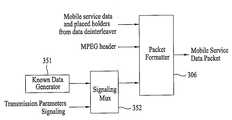
도 20은 본 발명에 따른 전송 파라미터를 패킷 포맷터에서 삽입하여 전송하기 위한 일 실시예를 보인 도면20 illustrates an embodiment for inserting and transmitting a transmission parameter in a packet formatter according to the present invention.
도 21은 본 발명에 따른 전송 파라미터를 필드 동기 세그먼트 영역에 삽입하여 전송하기 위한 일 실시예를 보인 도면21 illustrates an embodiment for inserting and transmitting a transmission parameter into a field sync segment region according to the present invention;
도 22는 본 발명에 따른 수신 시스템의 일 실시예를 보인 구성 블록도22 is a block diagram showing an embodiment of a receiving system according to the present invention;
도 23은 본 발명에 따른 기지 데이터가 주기적으로 일반 데이터에 삽입되는 예를 보인 데이터 구조도23 is a data structure diagram showing an example in which known data is periodically inserted into general data according to the present invention.
도 24의 (a) 내지 (c)는 포스트 고스트가 있을 경우의 메인 신호와 고스트 신호와의 관계를 보인 도면24A to 24C show a relationship between a main signal and a ghost signal when there is a post ghost;
도 25의 (a) 내지 (c)는 프리 고스트가 있을 경우의 메인 신호와 고스트 신호와의 관계를 보인 도면25 (a) to 25 (c) are diagrams showing a relationship between a main signal and a ghost signal when there is a preghost;
도 26은 본 발명에 따른 채널 등화기의 일 실시예를 보인 구성 블록도26 is a block diagram illustrating an embodiment of a channel equalizer according to the present invention.
도 27은 본 발명에 따른 채널 등화기의 다른 실시예를 보인 구성 블록도27 is a block diagram showing another embodiment of the channel equalizer according to the present invention;
도 28은 본 발명에 따른 채널 등화기의 또 다른 실시예를 보인 구성 블록도28 is a block diagram showing another embodiment of a channel equalizer according to the present invention
도 29는 본 발명에 따른 채널 등화기의 또 다른 실시예를 보인 구성 블록도29 is a block diagram showing another embodiment of a channel equalizer according to the present invention
도 30은 본 발명에 따른 채널 등화기의 또 다른 실시예를 보인 구성 블록도30 is a block diagram showing another embodiment of a channel equalizer according to the present invention
도 31은 본 발명에 따른 채널 등화기의 또 다른 실시예를 보인 구성 블록도31 is a block diagram showing another embodiment of a channel equalizer according to the present invention
도 32는 본 발명에 따른 선형 보간 예를 보인 도면32 illustrates an example of linear interpolation according to the present invention.
도 33은 본 발명의 선형 보간에 따른 중첩 & 세이브의 일예를 보인 도면33 illustrates an example of overlapping & saving according to linear interpolation according to the present invention.
도 34는 본 발명의 선형 보간에 따른 중첩 & 세이브의 다른 예를 보인 도면34 illustrates another example of overlapping & saving according to linear interpolation according to the present invention.
도 35는 본 발명에 따른 선형 외삽 예를 보인 도면35 shows an example of linear extrapolation according to the present invention.
도 36은 본 발명의 선형 외삽에 따른 중첩 & 세이브의 일예를 보인 도면36 shows an example of overlapping & saving according to the linear extrapolation of the present invention.
도 37은 본 발명에 따른 채널 등화기의 또 다른 실시예를 보인 구성 블록도37 is a block diagram showing another embodiment of a channel equalizer according to the present invention
도 38은 본 발명에 따른 채널 등화기의 또 다른 실시예를 보인 구성 블록도38 is a block diagram illustrating another embodiment of a channel equalizer according to the present invention.
도 39는 본 발명에 따른 채널 등화기의 또 다른 실시예를 보인 구성 블록도Fig. 39 is a block diagram showing another embodiment of a channel equalizer according to the present invention.
도 40은 본 발명에 따른 채널 등화기의 또 다른 실시예를 보인 구성 블록도40 is a block diagram illustrating another embodiment of a channel equalizer according to the present invention.
도 41은 본 발명에 따른 CIR 추정기의 일 실시예를 보인 상세 블록도Figure 41 is a detailed block diagram illustrating one embodiment of a CIR estimator in accordance with the present invention.
도 42는 본 발명에 따른 채널 등화기의 또 다른 실시예를 보인 구성 블록도42 is a block diagram illustrating another embodiment of a channel equalizer according to the present invention.
도 43은 도 42의 잔류 반송파 위상 에러 추정부의 일 실시예를 보인 구성 블록도FIG. 43 is a block diagram illustrating an embodiment of a residual carrier phase error estimator of FIG. 42.
도 44는 도 42의 위상 에러 검출기의 일 실시예를 보인 구성 블록도44 is a block diagram illustrating an embodiment of the phase error detector of FIG. 42.
도 45는 도 42의 위상 보상기의 일 실시예를 보인 구성 블록도45 is a block diagram illustrating an embodiment of the phase compensator of FIG. 42.
도 46은 본 발명에 따른 에러 정정 복호화 과정의 예를 보인 도면46 shows an example of an error correction decoding process according to the present invention.
*도면의 주요부분에 대한 부호의 설명*Description of the Related Art [0002]
901 : 튜너902 : 복조기901
903 : 등화기904 : 기지 데이터 검출기903: Equalizer 904: Known Data Detector
905 : 블록 복호기906 : 데이터 디포맷터905: block decoder 906: data formatter
907 : RS 프레임 복호기908,911 : 데이터 디랜더마이저907 RS frame decoder 908,911 data derandomizer
909 : 데이터 디인터리버910 : RS 복호기909: data deinterleaver 910: RS decoder
1001 : 제1 FFT부 1002 : CIR 추정기1001: first FFT unit 1002: CIR estimator
1003 : 제2 FFT부1004 : 계수 연산기1003: second FFT unit 1004: coefficient calculator
1005 : 왜곡 보상부1006 : IFFT부1005: distortion compensation unit 1006: IFFT unit
본 발명은 디지털 방송을 송신하고 수신하기 위한 디지털 방송 시스템 및 데이터 처리 방법에 관한 것이다.The present invention relates to a digital broadcasting system and a data processing method for transmitting and receiving digital broadcasting.
디지털 방송 중 북미 및 국내에서 디지털 방송 표준으로 채택된 VSB(Vestigial Sideband) 전송 방식은 싱글 캐리어 방식이므로 열악한 채널 환경에서는 수신 시스템의 수신 성능이 떨어질 수 있다. 특히 휴대용이나 이동형 방송 수신기의 경우에는 채널 변화 및 노이즈에 대한 강건성이 더욱 요구되므로, 상기 VSB 전송 방식으로 모바일 서비스 데이터를 전송하는 경우 수신 성능이 더욱 떨어지게 된다.VSB (Vestigial Sideband) transmission system adopted as a digital broadcasting standard in North America and Korea in digital broadcasting is a single carrier system, so reception performance of a receiving system may be deteriorated in a poor channel environment. Particularly, in the case of a portable or mobile broadcast receiver, robustness against channel change and noise is further required, so that when the mobile service data is transmitted using the VSB transmission method, the reception performance is further degraded.
따라서 본 발명은 채널 변화 및 노이즈에 강한 디지털 방송 시스템 및 데이터 처리 방법을 제공함에 있다.Accordingly, the present invention provides a digital broadcasting system and a data processing method that are robust against channel variation and noise.
본 발명은 모바일 서비스 데이터에 대해 추가의 부호화를 수행하여 수신 시스템으로 전송함으로써, 수신 시스템의 수신 성능을 향상시키도록 하는 디지털 방송 시스템 및 데이터 처리 방법을 제공함에 있다.The present invention provides a digital broadcasting system and a data processing method for improving the reception performance of a reception system by performing additional encoding on mobile service data and transmitting the same to a reception system.
본 발명은 송/수신측의 약속에 의해 알고 있는 기지 데이터를 데이터 영역의 소정 영역에 삽입하여 전송함으로써, 수신 시스템의 수신 성능을 향상시키도록 하는 디지털 방송 시스템 및 데이터 처리 방법을 제공함에 있다.The present invention provides a digital broadcasting system and a data processing method for enhancing reception performance of a receiving system by inserting known data known by the promise of a transmitting / receiving side into a predetermined area of a data area and transmitting the data.
본 발명은 수신 시스템에서 채널을 등화하는 장치 및 방법을 제공함에 있다.The present invention provides an apparatus and method for equalizing a channel in a receiving system.
상기 목적을 달성하기 위하여, 본 발명의 일 실시예에 따른 전송 시스템은 서비스 다중화기와 송신기를 포함할 수 있다. 상기 서비스 다중화기는 모바일 서비스 데이터와 메인 서비스 데이터를 기 설정된 데이터 율로 다중화하여 송신기로 전송할 수 있다. 상기 송신기는 서비스 다중화기에서 전송되는 모바일 서비스 데이터에 대해 추가의 부호화를 수행하고, 부호화가 수행된 다수개의 모바일 서비스 데이터 패킷을 모아 데이터 그룹을 형성할 수 있다. 상기 송신기는 모바일 서비스 데이터를 포함하는 모바일 서비스 데이터 패킷과 메인 서비스 데이터를 포함하는 메인 서비스 데이터 패킷을 패킷 단위로 다중화하여 수신 시스템으로 전송할 수 있다. 이때 상기 송신기는 데이터 그룹과 메인 서비스 데이터 패킷을 버스트 구조로 다중화할 수 있으며, 상기 버스트는 데이터 그룹이 포함되는 버스트 온 구간과 데이터 그룹이 포함되지 않는 버스트 오프 구간으로 구분할 수 있다.In order to achieve the above object, a transmission system according to an embodiment of the present invention may include a service multiplexer and a transmitter. The service multiplexer may multiplex the mobile service data and the main service data at a preset data rate and transmit them to the transmitter. The transmitter may perform additional encoding on mobile service data transmitted from the service multiplexer, and collect a plurality of mobile service data packets on which encoding is performed to form a data group. The transmitter may multiplex a mobile service data packet including mobile service data and a main service data packet including main service data in packet units and transmit the packet to a receiving system. In this case, the transmitter may multiplex the data group and the main service data packet into a burst structure, and the burst may be divided into a burst on period including a data group and a burst off period without a data group.
상기 데이터 그룹은 메인 서비스 데이터의 간섭 정도에 따라 다수개의 영역으로 구분할 수 있다. 상기 메인 서비스 데이터의 간섭이 없는 영역에는 주기적으로 긴 기지 데이터 열을 삽입할 수 있다.The data group may be divided into a plurality of areas according to the degree of interference of the main service data. It is possible to periodically insert a long known data sequence into an area where no interference occurs in the main service data.
본 발명의 일 실시예에 따른 수신 시스템은 상기 기지 데이터 열을 복조 및 채널 등화에 이용할 수 있다.A receiving system according to an embodiment of the present invention may use the known data stream for demodulation and channel equalization.
본 발명에 따른 채널 등화기는 다수개의 영역으로 구분되는 데이터 그룹 내 각 영역의 특성에 따라 다른 방식으로 채널 등화를 수행할 수 있다.The channel equalizer according to the present invention may perform channel equalization in different ways according to the characteristics of each region in the data group divided into a plurality of regions.
상기 본 발명에 따른 채널 등화기는 잔류 반송파 위상 에러를 추정하여 채널 등화된 신호로부터 보상할 수 있다.The channel equalizer according to the present invention can estimate the residual carrier phase error to compensate from the channel equalized signal.
상기 수신 시스템은 모바일 서비스 데이터만을 수신하는 경우, 버스트 온 구 간에서만 전원을 온하여 모바일 서비스 데이터를 처리할 수 있다.When the reception system receives only mobile service data, the reception system may turn on power only in the burst on period to process mobile service data.
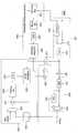
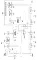
이를 위해 본 발명의 일 실시예에 따른 수신 시스템 내 채널 등화기는 주파수 영역 변환부, CIR 추정부, CIR 연산부, 계수 계산부, 및 왜곡 보상부를 포함할 수 있다. 상기 주파수 영역 변환부는 기지 데이터 열이 일반 데이터에 주기적으로 삽입되어 전송되면 이를 수신하고, 수신된 데이터를 주파수 영역으로 변환한다. 상기 CIR 추정부는 기지 데이터 구간동안 수신되는 데이터와 수신측에서 발생한 기지 데이터를 이용하여 채널 임펄스 응답(CIR)을 추정한다. 상기 CIR 연산부는 수신되는 일반 데이터의 특성에 따라 상기 CIR 추정부에서 추정된 채널 임펄스 응답(CIR)을 보간하거나 외삽한다. 상기 계수 계산부는 상기 CIR 연산부에서 출력되는 채널 임펄스 응답(CIR)을 주파수 영역으로 변환한 후 등화 계수를 계산하여 출력한다. 상기 왜곡 보상부는 상기 주파수 영역 변환부에서 주파수 영역으로 변환된 데이터에 상기 계수 계산부의 등화 계수를 곱하여 채널 왜곡을 보상한다.To this end, the channel equalizer in the reception system according to the embodiment of the present invention may include a frequency domain transform unit, a CIR estimator, a CIR calculator, a coefficient calculator, and a distortion compensator. The frequency domain converter receives the known data string periodically inserted into the general data and transmits the received data stream, and converts the received data into the frequency domain. The CIR estimator estimates a channel impulse response (CIR) using data received during a known data interval and known data generated at a receiver. The CIR calculator interpolates or extrapolates a channel impulse response (CIR) estimated by the CIR estimator according to characteristics of the received general data. The coefficient calculator calculates and outputs an equalization coefficient after converting a channel impulse response (CIR) output from the CIR calculator into a frequency domain. The distortion compensator compensates for channel distortion by multiplying the data transformed by the frequency domain transform unit into the frequency domain by the equalization coefficient of the coefficient calculator.
본 발명의 다른 목적, 특징 및 잇점들은 첨부한 도면을 참조한 실시예들의 상세한 설명을 통해 명백해질 것이다.Other objects, features and advantages of the present invention will become apparent from the following detailed description of embodiments taken in conjunction with the accompanying drawings.
이하 상기의 목적을 구체적으로 실현할 수 있는 본 발명의 바람직한 실시예를 첨부한 도면을 참조하여 설명한다. 이때 도면에 도시되고 또 이것에 의해서 설명되는 본 발명의 구성과 작용은 적어도 하나의 실시예로서 설명되는 것이며, 이것에 의해서 본 발명의 기술적 사상과 그 핵심 구성 및 작용이 제한되지는 않는다.DETAILED DESCRIPTION OF THE PREFERRED EMBODIMENTS Hereinafter, preferred embodiments of the present invention will be described with reference to the accompanying drawings. At this time, the configuration and operation of the present invention shown in the drawings and described by it will be described as at least one embodiment, by which the technical spirit of the present invention and its core configuration and operation is not limited.
본 발명에서 사용되는 용어의 정의Definitions of terms used in the present invention
본 발명에서 사용되는 용어는 본 발명에서의 기능을 고려하면서 가능한 현재 널리 사용되는 일반적인 용어를 선택하였으나, 이는 당분야에 종사하는 기술자의 의도 또는 관례 또는 새로운 기술의 출현 등에 따라 달라질 수 있다. 또한 특정한 경우는 출원인이 임의로 선정한 용어도 있으며, 이 경우 해당되는 발명의 설명 부분에서 상세히 그 의미를 기재할 것이다. 따라서 본 발명에서 사용되는 용어는 단순한 용어의 명칭이 아닌 그 용어가 가지는 의미와 본 발명의 전반에 걸친 내용을 토대로 정의되어야 함을 밝혀두고자 한다.The terms used in the present invention were selected as widely used general terms as possible in consideration of the functions in the present invention, but may vary according to the intention or custom of the person skilled in the art or the emergence of new technologies. In addition, in certain cases, there is a term arbitrarily selected by the applicant, and in this case, the meaning will be described in detail in the corresponding description of the invention. Therefore, it is to be understood that the term used in the present invention should be defined based on the meaning of the term rather than the name of the term, and on the contents of the present invention throughout.
본 발명에서 사용되는 용어 중 메인 서비스 데이터는 고정형 수신 시스템에서 수신할 수 있는 데이터로서, 오디오/비디오(A/V) 데이터를 포함할 수 있다. 즉, 상기 메인 서비스 데이터에는 HD(High Definition) 또는 SD(Standard Definition)급의 A/V 데이터가 포함될 수 있으며, 데이터 방송을 위한 각종 데이터가 포함될 수도 있다. 그리고 기지(Known) 데이터는 송/수신측의 약속에 의해 미리 알고 있는 데이터이다.Among the terms used in the present invention, main service data may include audio / video (A / V) data as data that can be received by a fixed receiving system. That is, the main service data may include HD (High Definition) or SD (Standard Definition) A / V data, and various data for data broadcasting may be included. The known data is previously known data by the promise of the transmitting / receiving side.
또한 본 발명에서 모바일(mobile) 서비스 데이터는 모바일(Mobile) 서비스 데이터, 퍼데스트리언(Pedestrian) 서비스 데이터, 핸드헬드(Handheld) 서비스 데이터 중 적어도 하나를 포함하며, 설명의 편의를 위해 본 발명에서는 모바일 서비스 데이터라 한다. 이때 상기 모바일 서비스 데이터는 M/P/H(Mobile/Pedestrian/Handheld) 서비스 데이터뿐만 아니라, 이동이나 휴대를 의미하는 서비스 데이터는 어느 것이나 포함될 수 있으며, 따라서 상기 모바일 서비스 데이터는 상기 M/P/H 서비스 데이터로 제한되지 않을 것이다.Also, in the present invention, the mobile service data includes at least one of mobile service data, pedestrian service data, and handheld service data. For convenience of description, Service data. At this time, the mobile service data may include not only M / P / H (Mobile / Pedestrian / Handheld) service data, but also service data indicating movement or carrying, Service data.
상기와 같이 정의된 모바일 서비스 데이터는 프로그램 실행 파일, 주식 정보 등과 같이 정보를 갖는 데이터일 수도 있고, A/V 데이터일 수도 있다. 특히 상기 모바일 서비스 데이터는 휴대용이나 이동형 단말기(또는 방송 수신기)를 위한 서비스 데이터로서 메인 서비스 데이터에 비해서 작은 해상도와 작은 데이터 율을 가지는 A/V 데이터가 될 수도 있다. 예를 들어, 기존 메인 서비스를 위해 사용하는 A/V 코덱(Codec)이 MPEG-2 코덱(Codec)이라면, 모바일 서비스를 위한 A/V 코덱(Codec)으로는 보다 영상 압축 효율이 좋은 MPEG-4 AVC(Advanced Video Coding), SVC(Scalable Video Coding) 등의 방식이 사용될 수 있다. 또한 상기 모바일 서비스 데이터로는 어떠한 종류의 데이터라도 전송될 수 있다. 일례로 실시간으로 교통 정보를 방송하기 위한 TPEG(Transport Protocol Expert Group) 데이터가 서비스 될 수도 있다.The mobile service data defined as described above may be data having information such as a program execution file, stock information, or the like, or may be A / V data. In particular, the mobile service data may be service data for a portable or mobile terminal (or broadcast receiver), and may be A / V data having a smaller resolution and smaller data rate than the main service data. For example, if the A / V codec used for the existing main service is an MPEG-2 codec, the A / V codec for mobile service may be MPEG-4 AVC (Advanced Video Coding), and SVC (Scalable Video Coding). Also, any kind of data can be transmitted as the mobile service data. For example, TPEG (Transport Protocol Expert Group) data for broadcasting traffic information in real time may be serviced.
또한 상기 모바일 서비스 데이터를 이용한 데이터 서비스로는 날씨 서비스, 교통 서비스, 증권 서비스, 시청자 참여 퀴즈 프로그램, 실시간 여론 조사, 대화형 교육 방송, 게임 서비스, 드라마의 줄거리, 등장인물, 배경음악, 촬영장소 등에 대한 정보 제공 서비스, 스포츠의 과거 경기 전적, 선수의 프로필 및 성적에 대한 정보 제공 서비스, 상품 정보 및 이에 대한 주문 등이 가능하도록 하는 서비스별, 매체별, 시간별, 또는 주제별로 프로그램에 대한 정보 제공 서비스 등이 될 수 있으며, 본 발명은 이에 한정하지는 않는다.The data service using the mobile service data may include a weather service, a traffic service, a securities service, a viewer participation quiz program, a real-time opinion survey, an interactive education broadcast, a game service, a plot of a drama, Providing information on programs by service, media, hourly, or topic that enables information service for information, information on past competitions of sports, profiles and grades of athletes, and product information and orders Or the like, and the present invention is not limited thereto.
본 발명의 전송 시스템은 기존 수신 시스템에서 메인 서비스 데이터를 수신하는데 전혀 영향을 주지 않으면서(backward compatible), 동일한 물리적 채널에 메인 서비스 데이터와 모바일 서비스 데이터를 다중화하여 전송할 수 있도록 한다.The transmission system according to the present invention is capable of multiplexing the main service data and the mobile service data on the same physical channel without any influence on receiving the main service data in the existing receiving system.
본 발명의 전송 시스템은 모바일 서비스 데이터에 대해 추가적인 부호화를 수행하고, 송/수신측 모두가 미리 알고 있는 데이터 즉, 기지(known) 데이터를 삽입하여 전송할 수 있도록 한다.The transmission system of the present invention performs additional coding on the mobile service data and inserts known data, that is, known data, into both the transmitting and receiving sides.
이러한 본 발명에 따른 전송 시스템을 사용하면 수신 시스템에서는 모바일 서비스 데이터의 이동 수신이 가능하며, 또한 채널에서 발생하는 각종 왜곡과 노이즈에도 모바일 서비스 데이터의 안정적인 수신이 가능하다.With the transmission system according to the present invention, mobile service data can be received and received in the receiving system, and stable reception of mobile service data is possible even with various distortions and noises occurring in the channel.
전송 시스템의 개략적인 설명A brief description of the transmission system
도 1은 이러한 본 발명을 적용하기 위한 전송 시스템의 일 실시예를 보인 개략도로서, 서비스 다중화기(Service Multiplexer)(100)와 송신기(Transmitter)(200)를 포함할 수 있다.FIG. 1 is a schematic diagram illustrating an embodiment of a transmission system for applying the present invention. The
여기서 상기 서비스 다중화기(100)는 각 방송국의 스튜디오에 위치하고, 송신기(200)는 스튜디오로부터 거리가 떨어진 지역(site)에 위치한다. 이때 상기 송신기(200)는 복수개의 서로 다른 지역에 위치할 수도 있다. 그리고 일 실시예로 상기 복수개의 송신기는 동일한 주파수를 공유할 수 있으며, 이 경우 복수개의 송신기는 모두 동일한 신호를 송신한다. 그러면 수신 시스템에서는 채널 등화기가 반사파로 인한 신호 왜곡을 보상하여 원 신호를 복원할 수가 있다. 다른 실시예로, 상기 복수개의 송신기는 동일 채널에 대해 서로 다른 주파수를 가질 수도 있다.Here, the
상기 서비스 다중화기와 원격지에 위치한 각 송신기간의 데이터 통신은 여러 가지 방법이 이용될 수 있으며, 일 실시예로 SMPTE-310M(Synchronous Serial Interface for transport of MPEG-2 data)과 같은 인터페이스 규격이 사용될 수도 있다. 상기 SMPTE-310M 인터페이스 규격에서는 서비스 다중화기의 출력 데이터 율이 일정한 데이터 율로 정해져 있다. 예를 들어, 8VSB의 경우 19.39 Mbps로 정해져 있고, 16VSB의 경우 38.78 Mbps로 정해져 있다. 또한 기존 8VSB 방식의 전송 시스템에서는 한 개의 물리적인 채널에 데이터 율이 약 19.39 Mbps인 트랜스포트 스트림(Transport Stream ; TS) 패킷을 전송할 수 있다. 기존 전송 시스템과 역방향 호환성을 가지는 본 발명에 따른 송신기에서도, 상기 모바일 서비스 데이터에 대하여 추가의 부호화를 수행한 후 이를 메인 서비스 데이터와 TS 패킷 형태로 다중화하여 전송하는데, 이때에도 다중화된 TS 패킷의 데이터 율은 약 19.39 Mbps가 된다.Various methods may be used for data communication between the service multiplexer and each transmitter located at a remote location, and as an example, an interface standard such as Synchronous Serial Interface for transport of MPEG-2 data (SMPTE-310M) may be used. . In the SMPTE-310M interface standard, the output data rate of the service multiplexer is fixed at a constant data rate. For example, it is set at 19.39 Mbps for 8VSB and 38.78 Mbps for 16VSB. Also, in the conventional 8VSB transmission system, a transport stream (TS) packet having a data rate of about 19.39 Mbps can be transmitted to one physical channel. Even in the transmitter according to the present invention, which is backward compatible with the existing transmission system, the mobile service data is further encoded and then multiplexed with the main service data in the form of a TS packet. At this time, The rate is about 19.39 Mbps.
이때 상기 서비스 다중화기(100)는 적어도 한 종류의 모바일 서비스 데이터와 각 모바일 서비스를 위한 PSI(Program Specific Information)/PSIP(Program and System Information Protocol) 테이블 데이터를 입력받아 각각 트랜스포트 스트림(TS) 패킷으로 인캡슐레이션(encapsulation)한다. 또한 상기 서비스 다중화기(100)는 적어도 한 종류의 메인 서비스 데이터와 각 메인 서비스를 위한 PSI/PSIP 테이블 데이터를 입력받아 TS 패킷으로 인캡슐레이션(encapsulation)한다. 이어 상기 TS 패킷들을 기 설정된 다중화 규칙에 따라 다중화하여 송신기(200)로 출력한다.At this time, the
서비스 다중화기Service multiplexer
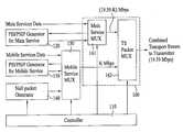
도 2는 상기 서비스 다중화기의 일 실시예를 보인 상세 블록도로서, 상기 서비스 다중화기의 전반적인 동작을 제어하는 제어기(Controller)(110), 메인 서비스를 위한 PSI/PSIP 발생기(120), 모바일 서비스를 위한 PSI/PSIP 발생기(130), 널 패킷 발생기(140), 모바일 서비스 다중화기(150), 및 트랜스포트 다중화기(160)를 포함할 수 있다.FIG. 2 is a detailed block diagram illustrating an embodiment of the service multiplexer. The
상기 트랜스포트 다중화기(160)는 메인 서비스 다중화기(161), 및 트랜스포트 스트림(Transport Stream ; TS) 패킷 다중화기(162)를 포함할 수 있다.The
도 2를 보면, 적어도 한 종류의 압축 부호화된 메인 서비스 데이터와 상기 메인 서비스를 위해 PSI/PSIP 발생기(120)에서 발생된 PSI/PSIP 테이블 데이터는 트랜스포트 다중화기(160)의 메인 서비스 다중화기(161)로 입력된다. 상기 메인 서비스 다중화기(161)는 입력되는 메인 서비스 데이터와 PSI/PSIP 테이블 데이터를 각각 MPEG-2 TS 패킷 형태로 인캡슐레이션(encapsulation)하고, 이러한 TS 패킷들을 다중화하여 TS 패킷 다중화기(162)로 출력한다. 상기 메인 서비스 다중화기(161)에서 출력되는 데이터 패킷을 설명의 편의를 위해 메인 서비스 데이터 패킷이라 하기로 한다.Referring to FIG. 2, at least one kind of compressed coded main service data and PSI / PSIP table data generated by the PSI /
또한 적어도 한 종류의 압축 부호화된 모바일 서비스 데이터와 상기 모바일 서비스를 위해 PSI/PSIP 발생기(130)에서 발생된 PSI/PSIP 테이블 데이터는 모바일 서비스 다중화기(150)로 입력된다.Also, at least one kind of compression-coded mobile service data and PSI / PSIP table data generated by the PSI /
상기 모바일 서비스 다중화기(150)는 입력되는 모바일 서비스 데이터와 PSI/PSIP 테이블 데이터를 각각 MPEG-2 TS 패킷 형태로 인캡슐레이션(encapsulation)하고, 이러한 TS 패킷들을 다중화하여 TS 패킷 다중화기(162)로 출력한다. 상기 모바일 서비스 다중화기(150)에서 출력되는 데이터 패킷을 설명의 편의를 위해 모바일 서비스 데이터 패킷이라 하기로 한다.The
이때, 상기 송신기(200)에서 상기 메인 서비스 데이터 패킷과 모바일 서비스 데이터 패킷을 구분하여 처리하기 위해서는 식별 정보가 필요하다. 상기 식별 정보는 송/수신측의 약속에 의해 미리 정해진 값을 이용할 수도 있고, 별도의 데이터로 구성할 수도 있으며, 해당 데이터 패킷 내 기 설정된 위치의 값을 변형시켜 이용할 수도 있다.At this time, the
본 발명에서는 일 실시예로, 메인 서비스 데이터 패킷과 모바일 서비스 데이터 패킷에 각기 서로 다른 PID(Packet Identifier)를 할당하여 구분할 수 있다.In an embodiment of the present invention, different PIDs (Packet Identifiers) may be allocated to the main service data packet and the mobile service data packet, respectively.
다른 실시예로, 모바일 서비스 데이터 패킷의 헤더 내 동기 바이트를 변형함에 의해, 해당 서비스 데이터 패킷의 동기 바이트 값을 이용하여 구분할 수도 있다. 예를 들어, 메인 서비스 데이터 패킷의 동기 바이트는 ISO/IEC13818-1에서 규정한 값(예를 들어, 0x47)을 변형없이 그대로 출력하고, 모바일 서비스 데이터 패킷의 동기 바이트는 변형시켜 출력함에 의해 메인 서비스 데이터 패킷과 모바일 서비스 데이터 패킷을 구분할 수 있다. 반대로 메인 서비스 데이터 패킷의 동기 바이트를 변형하고, 모바일 서비스 데이터 패킷의 동기 바이트를 변형없이 그대로 출력함에 의해 메인 서비스 데이터 패킷과 모바일 서비스 데이터 패킷을 구분할 수 있다.In another embodiment, by modifying the synchronization byte in the header of the mobile service data packet, the synchronization byte value of the service data packet can be used to distinguish the mobile service data packet. For example, the synchronous byte of the main service data packet is output without modification as it is defined in ISO / IEC13818-1 (for example, 0x47), and the synchronous byte of the mobile service data packet is transformed and output, It is possible to distinguish between the data packet and the mobile service data packet. Conversely, the main service data packet and the mobile service data packet can be distinguished by modifying the synchronization byte of the main service data packet and outputting the synchronization byte of the mobile service data packet without modification.
상기 동기 바이트를 변형하는 방법은 여러 가지가 있을 수 있다. 예를 들어, 동기 바이트를 비트별로 반전시키거나, 일부 비트만을 반전시킬 수도 있다.There are various methods for modifying the sync byte. For example, the synchronization byte may be inverted bit by bit, or only some bits may be inverted.
이와 같이 상기 메인 서비스 데이터 패킷과 모바일 서비스 데이터 패킷을 구분할 수 있는 식별 정보는 어느 것이나 가능하므로, 본 발명은 상기된 실시예들로 한정되지 않을 것이다.As such, any identification information capable of distinguishing the main service data packet from the mobile service data packet may be used. Thus, the present invention will not be limited to the above-described embodiments.
한편 상기 트랜스포트 다중화기(160)는 기존 디지털 방송 시스템에서 사용하는 트랜스포트 다중화기를 그대로 사용할 수 있다. 즉, 모바일 서비스 데이터를 메인 서비스 데이터와 다중화하여 전송하기 위하여 메인 서비스의 데이터 율을 (19.39-K) Mbps의 데이터 율로 제한하고, 나머지 데이터 율에 해당하는 K Mbps를 모바일 서비스에 할당하는 것이다. 이렇게 하면, 이미 사용되고 있는 트랜스포트 다중화기를 변경하지 않고 그대로 사용할 수 있다.Meanwhile, the
상기 트랜스포트 다중화기(160)는 메인 서비스 다중화기(161)에서 출력되는 메인 서비스 데이터 패킷과 모바일 서비스 다중화기(150)에서 출력되는 모바일 서비스 데이터 패킷을 다중화하여 송신기(200)로 전송한다.The
그런데 상기 모바일 서비스 다중화기(150)의 출력 데이터 율이 K Mbps가 안되는 경우가 발생할 수 있다. 이 경우 상기 모바일 서비스 다중화기(150)는 출력 데이터 율이 K Mbps가 되도록 널 패킷 발생기(140)에서 발생된 널 데이터 패킷을 다중화하여 출력한다. 즉, 상기 널 패킷 발생기(140)는 모바일 서비스 다중화기(150)의 출력 데이터 율을 일정하게 맞추기 위하여 널 데이터 패킷을 발생하여 모바일 서비스 다중화기(150)로 출력한다.However, it may happen that the output data rate of the
예를 들어, 상기 서비스 다중화기(100)에서 19.39 Mbps 중 K Mbps를 모바일 서비스 데이터에 할당하고, 그 나머지인 (19.39-K) Mbps를 메인 서비스 데이터에 할당한다고 하면, 실제로 상기 서비스 다중화기(100)에서 다중화되는 모바일 서비스 데이터의 데이터 율은 K Mbps보다 작아진다. 이는 상기 모바일 서비스 데이터의 경우, 송신기의 전 처리기(pre-processor)에서 추가의 부호화를 수행하여 데이터 량이 늘리기 때문이다. 이로 인해 서비스 다중화기(100)에서 전송할 수 있는 모바일 서비스 데이터의 데이터 율(data rate)이 K Mbps보다 작아지게 된다.For example, if K Mbps of 19.39 Mbps is assigned to mobile service data in the
일 예로, 상기 송신기의 전처리기에서는 모바일 서비스 데이터에 대해 적어도 1/2 부호율 이하의 부호화를 수행하므로, 전처리기의 출력 데이터의 양은 입력 데이터의 양보다 2배 이상 많게 된다. 따라서 서비스 다중화기(100)에서 다중화되는 메인 서비스 데이터의 데이터 율과 모바일 서비스 데이터의 데이터 율의 합은 항상 19.39 Mbps 보다 작거나 같게 된다.For example, the preprocessor of the transmitter performs coding of at least a half coding rate for mobile service data, so that the amount of output data of the preprocessor becomes twice as much as the amount of input data. Therefore, the sum of the data rate of the main service data multiplexed by the
따라서 상기 서비스 다중화기(100)에서 출력되는 최종 출력 데이터 율을 일정한 데이터 율(예를 들어, 19.39 Mbps)로 맞추기 위해, 상기 널 패킷 발생기(140)에서는 모자라는 데이터 율만큼 널 데이터 패킷을 생성하여 모바일 서비스 다중화기(150)로 출력한다.Accordingly, in order to adjust the final output data rate output from the
그러면 상기 모바일 서비스 다중화기(150)에서는 입력되는 모바일 서비스 데이터와 PSI/PSIP 테이블 데이터를 각각 MPEG-2 TS 패킷 형태로 인캡슐레이션(encapsulation)하고, 이러한 TS 패킷들과 널 데이터 패킷을 다중화하여 TS 패킷 다중화기(162)로 출력한다.Then, the
상기 TS 패킷 다중화기(162)는 메인 서비스 다중화기(161)에서 출력되는 메인 서비스 데이터 패킷과 모바일 서비스 다중화기(150)에서 출력되는 모바일 서비스 데이터 패킷을 다중화하여 19.39 Mbps 데이터 율로 송신기(200)로 전송한다.The
본 발명에서는 상기 모바일 서비스 다중화기(150)에서 널 데이터 패킷을 입 력받는 것을 일 실시예로 한다. 이는 일 실시예일 뿐이며, 다른 실시예로 상기 TS 패킷 다중화기(162)에서 널 데이터 패킷을 입력받아 최종 데이터 율을 일정한 데이터 율로 맞출 수도 있다. 상기 널 데이터 패킷의 출력 경로 및 다중화 규칙은 제어부(110)의 제어에 의해 이루어진다. 상기 제어부(110)는 상기 모바일 서비스 다중화기(150), 트랜스포트 다중화기(160)의 메인 서비스 다중화기(161), TS 패킷 다중화기(162)에서의 다중화 및 널 패킷 발생기(140)에서의 널 데이터 패킷의 발생을 제어한다.According to an embodiment of the present invention, a null data packet is input by the
이때 상기 송신기(200)에서는 상기 서비스 다중화기(100)에서 전송하는 널 데이터 패킷을 수신 시스템으로 전송하지 않고 버린다.At this time, the
그리고 상기 송신기(200)에서 상기 널 데이터 패킷을 전송하지 않고 버리기 위해서는 상기 널 데이터 패킷을 구분할 수 있는 식별 정보가 필요하다. 상기 널 데이터 패킷을 구분하기 위한 식별 정보는 송/수신측의 약속에 의해 미리 정해진 값을 이용할 수도 있고, 별도의 데이터로 구성할 수도 있다. 예를 들어, 상기 널 데이터 패킷의 헤더 내 동기 바이트 값을 변형시켜 식별 정보로 이용할 수도 있고, transport_error_indicator 플래그(flag)를 식별 정보로 이용할 수도 있다.In order for the
본 발명에서는 널 데이터 패킷 내 헤더의 transport_error_indicator 플래그를 널 데이터 패킷을 구분할 수 있는 식별 정보로 이용하는 것을 일 실시예로 설명한다. 이 경우, 상기 널 데이터 패킷의 transport_error_indicator 플래그는 1로 셋팅하고, 상기 널 데이터 패킷 이외의 모든 데이터 패킷들의 transport_error_indicator 플래그는 0으로 리셋시켜 상기 널 데이터 패킷을 구분 하는 것을 일 실시예로 한다. 즉, 상기 널 패킷 발생기(140)에서 널 데이터 패킷을 발생시킬 때 널 데이터 패킷의 헤더의 필드 중에서 transport_error_indicator 플래그를 '1'로 세팅하여 전송한다면 송신기(200)에서 이를 구분하여 버릴 수 있다.In the present invention, the transport_error_indicator flag of a header in a null data packet is used as identification information for distinguishing a null data packet. In this case, the transport_error_indicator flag of the null data packet is set to 1, and the transport_error_indicator flag of all data packets other than the null data packet is reset to 0 to distinguish the null data packet. That is, when the null data packet is generated in the
상기 널 데이터 패킷을 구분하기 위한 식별 정보는 널 데이터 패킷을 구분할 수 있는 것은 어느 것이나 가능하므로 본 발명은 상기된 실시예들로 한정되지 않을 것이다.Since the identification information for identifying the null data packet can be classified into null data packets, the present invention is not limited to the above-described embodiments.
또한 본 발명은 다른 실시예로서, 상기 널 데이터 패킷의 적어도 일부, 또는 모바일 서비스를 위한 PSI/PSIP 테이블 중 적어도 하나의 테이블 또는 OM(Operations and Maintenance) 패킷(또는 OMP라 하기도 함.)에 전송 파라미터가 포함되어 있을 수 있다. 이 경우 송신기(200)에서는 상기 전송 파라미터를 추출하여 해당 블록으로 출력하며, 필요한 경우 수신 시스템으로도 전송한다.In another embodiment of the present invention, at least one table of at least a part of the null data packet or a PSI / PSIP table for a mobile service or an operation and maintenance (OM) packet (or an OMP) May be included. In this case, the
즉, 전송 시스템의 동작 및 관리를 위한 목적으로 OMP(Operations and Maintenance Packet) 라는 패킷이 정의되어 있다. 일 예로, 상기 OMP는 MPEG-2 TS 패킷의 형식을 따르며 해당 PID는 0x1FFA의 값을 가진다. 상기 OMP은 4바이트의 헤더와 184바이트의 페이로드로 구성된다. 상기 184 바이트 중 첫번째 바이트는 OM_type 필드로서 OM 패킷의 유형을 의미한다.That is, a packet called an Operations and Maintenance Packet (OMP) is defined for the purpose of operation and management of the transmission system. For example, the OMP conforms to the format of the MPEG-2 TS packet and the corresponding PID has a value of 0x1FFA. The OMP consists of a header of 4 bytes and a payload of 184 bytes. The first byte of the 184 bytes indicates the type of the OM packet as the OM_type field.
본 발명에서는 상기 전송 파라미터를 OMP의 형식으로 전송할 수 있으며, 이 경우 OM_type 필드의 미사용 필드 값들 중에서 미리 약속된 값을 사용하여, 송신기(200)에 전송 파라미터가 OMP으로 전송됨을 알릴 수 있다. 즉, 송신기(200)에서는 PID를 보고 OMP를 찾을 수 있으며, 상기 OMP 내 OM_type 필드를 파싱하여 해당 패킷의 OM_type 필드 다음에 전송 파라미터가 포함되어 있는지 여부를 알 수 있다.In the present invention, the transmission parameter can be transmitted in the form of OMP. In this case, it is possible to inform that the transmission parameter is transmitted as OMP to the
상기 전송 파라미터는 송/수신 시스템에서 모바일 서비스 데이터를 처리하는데 필요한 부가 정보들로서, 예를 들면 상기 전송 파라미터에는 데이터 그룹 정보, 데이터 그룹 내 영역(region) 정보, RS 프레임 정보, 수퍼 프레임 정보, 버스트 정보, 터보 코드 정보, RS 코드 정보 등이 포함될 수 있다. 또한 상기 버스트 정보에는 버스트 사이즈(size) 정보, 버스트 주기 정보, 다음 버스트까지의 시간 등이 포함될 수 있다. 상기 버스트 주기(period)는 동일한 종류의 모바일 서비스를 전송하는 버스트가 반복되는 주기(period)를 의미하고, 버스트 사이즈(size)는 하나의 버스트에 포함되는 데이터 그룹의 개수를 의미한다. 상기 데이터 그룹은 다수개의 모바일 서비스 데이터 패킷들을 포함하며, 이러한 데이터 그룹이 다수개 모여서 하나의 버스트를 형성한다. 그리고 버스트 구간(section)은 현재 버스트의 시작에서 다음 버스트의 시작까지를 의미하며, 데이터 그룹이 포함되는 구간(또는 버스트 온 구간이라 하기도 함)과 데이터 그룹이 포함되지 않는 구간(또는 버스트 오프 구간이라 하기도 함)으로 구분된다. 하나의 버스트 구간은 다수개의 필드들로 구성되는데, 하나의 필드는 하나의 데이터 그룹을 포함한다.The transmission parameter is additional information necessary for processing mobile service data in a transmission / reception system. For example, the transmission parameter includes data group information, region information in a data group, RS frame information, super frame information, and burst information. , Turbo code information, RS code information, and the like. The burst information may include burst size information, burst period information, time to the next burst, and the like. The burst period means a period in which bursts transmitting the same type of mobile service are repeated, and the burst size means the number of data groups included in one burst. The data group includes a plurality of mobile service data packets, and these data groups are gathered to form a burst. The burst section refers to the start of the current burst to the start of the next burst, and includes a section including a data group (also called a burst on section) and a section without a data group (or a burst off section). (Also referred to as below). One burst period consists of a plurality of fields, and one field includes one data group.
또한 상기 전송 파라미터에는 모바일 서비스 데이터를 전송하기 위해서 심볼 영역의 신호들이 어떤 방법으로 부호화되는지에 대한 정보, 메인 서비스 데이터와 모바일 서비스 데이터 또는 여러 종류의 모바일 서비스 데이터 간에 어떻게 다중화되는지에 대한 다중화 정보 등이 포함될 수도 있다.The transmission parameters include information on how signals in the symbol region are encoded in order to transmit the mobile service data, multiplex information on how the main service data is multiplexed with mobile service data or various types of mobile service data, and the like .
상기 전송 파라미터에 포함되는 정보들은 본 발명의 이해를 돕기 위한 일 실 시예일 뿐이며, 상기 전송 파라미터에 포함되는 정보들의 추가 및 삭제는 당업자에 의해 용이하게 변경될 수 있으므로 본 발명은 상기 실시예로 한정되지 않을 것이다.The information included in the transmission parameter is only an example to help understanding of the present invention, and the present invention is limited to the above embodiment because addition and deletion of information included in the transmission parameter can be easily changed by those skilled in the art. Will not be.
또한 상기 전송 파라미터들은 서비스 다중화기(100)에서 송신기(200)로 제공할 수도 있고, 송신기(200) 자체적으로 제어부(도시되지 않음)에서 설정하거나 외부에서 입력받을 수 있다.The transmission parameters may be provided from the
송신기transmitter
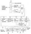
도 3은 본 발명의 일 실시예에 따른 송신기(200)의 구성 블록도로서, 역다중화기(210), 패킷 지터 경감기(Packet jitter mitigator)(220), 전 처리기(Pre-Processor)(230), 패킷 다중화기(240), 후처리기(Post-Processor)(250), 동기(Sync) 다중화기(260), 및 송신부(transmission unit)(270)를 포함할 수 있다.3 is a block diagram illustrating a
상기 역다중화기(210)는 서비스 다중화기(100)로부터 데이터 패킷이 수신되면, 수신된 데이터 패킷이 메인 서비스 데이터 패킷인지, 모바일 서비스 데이터 패킷인지, 아니면 널 데이터 패킷인지를 구분하여야 한다.When the data packet is received from the
일 실시예로, 상기 역다중화기(210)는 수신된 데이터 패킷 내 PID를 이용하여 모바일 서비스 데이터 패킷과 메인 서비스 데이터 패킷을 구분하고, transport_error_indicator 필드를 이용하여 널 데이터 패킷을 구분할 수 있다.In one embodiment, the
상기 역다중화기(210)에서 분리된 메인 서비스 데이터 패킷은 패킷 지터 경감기(220)로 출력되고, 모바일 서비스 데이터 패킷은 전처리기(230)로 출력되며, 널 데이터 패킷은 버려진다. 만일 상기 널 데이터 패킷에 전송 파라미터가 포함되 어 있다면 전송 파라미터가 추출되어 해당 블록으로 출력된 후 널 데이터 패킷은 버려진다.The main service data packet separated by the
상기 전처리기(230)는 역다중화기(210)에서 역다중화되어 출력되는 모바일 서비스 데이터 패킷 내 모바일 서비스 데이터에 대해 추가의 부호화 및 전송 프레임 상에 전송하고자 하는 데이터들의 용도에 따라 어느 특정 위치에 위치할 수 있도록 하는 데이터 그룹 형성 과정을 수행한다. 이는 상기 모바일 서비스 데이터가 노이즈 및 채널 변화에 빠르고 강력하게 대응하도록 하기 위해서이다. 상기 전처리기(230)는 추가의 부호화시에 상기 전송 파라미터를 참조할 수도 있다. 또한 상기 전처리기(230)는 모바일 서비스 데이터 패킷을 다수개 모아 데이터 그룹을 형성하고, 상기 데이터 그룹 내 기 설정된 영역에 기지 데이터, 모바일 서비스 데이터, RS 패리티 데이터, MPEG 헤더 등을 할당한다.The pre-processor 230 demultiplexes the mobile service data in the mobile service data packet demultiplexed and output by the
송신기 내의 전처리기The preprocessor in the transmitter
도 4는 본 발명에 따른 전처리기(230)의 일 실시예를 보인 구성 블록도로서, 데이터 랜더마이저(301), RS 프레임 부호기(302), 블록 처리기(303), 그룹 포맷터(304), 데이터 디인터리버(305), 및 패킷 포맷터(306)를 포함할 수 있다.4 is a block diagram illustrating an embodiment of a
이와 같이 구성된 전처리기(230) 내 데이터 랜더마이저(301)는 역다중화기(210)를 통해 입력되는 모바일 서비스 데이터를 포함하는 모바일 서비스 데이터 패킷을 랜더마이징시켜 RS 프레임 부호기(302)로 출력한다. 이때 상기 데이터 랜더마이저(301)에서 모바일 서비스 데이터에 대해 랜더마이징을 수행함으로써, 후처리기(250)의 데이터 랜더마이저(251)에서는 모바일 서비스 데이터에 대한 랜더마이징 과정을 생략할 수 있다.The data randomizer 301 in the
상기 RS 프레임 부호기(302)는 랜더마이즈되어 입력되는 모바일 서비스 데이터 패킷을 복수개 모아 RS 프레임을 구성하고, RS 프레임 단위로 에러 정정 부호화(encoding) 과정, 에러 검출 부호화 과정 중 적어도 하나의 과정을 수행한다. 이렇게 하면 모바일 서비스 데이터에 강건성을 부여하면서 전파 환경 변화에 의해서 발생할 수 있는 군집 에러를 흐트림으로써 극심하게 열악하고 빠르게 변하는 전파 환경에도 대응할 수 있게 된다. 또한 복수개의 RS 프레임을 모아 수퍼 프레임(Super Frame)을 구성하고, 수퍼 프레임 단위로 인터리빙(interleaving or permutation)을 수행할 수도 있다. 즉, 상기 RS 프레임 부호기(302)에서 수퍼 프레임의 각 열을 기 설정된 규칙으로 섞는 인터리빙을 수행하면, 수퍼 프레임 내에서 인터리빙 전후의 로우의 위치가 달라진다. 상기 수퍼 프레임 단위의 인터리빙을 수행하면, 다량의 에러가 발생한 구간이 매우 길어 복호하려는 한 개의 RS 프레임 내에 정정 불가능할 만큼의 에러가 포함되더라도 수퍼 프레임 전체에서는 이 에러들이 분산되므로 단일 RS 프레임과 비교하여 복호 능력이 향상된다.The
상기 RS 프레임 부호기(302)에서 에러 정정 부호화는 RS 부호화를 적용하고, 에러 검출 부호화는 CRC(Cyclic Redundancy Check) 부호화를 적용하는 것을 일 실시예로 한다. 상기 RS 부호화를 수행하면 에러 정정을 위해 사용될 패리티 데이터가 생성되고, CRC 부호화를 수행하면 에러 검출을 위해 사용될 CRC 데이터가 생성된다.According to an embodiment of the present invention, the
상기 RS 부호화는 FEC(Forward Error Correction) 중 하나이다. 상기 FEC는 전송 과정에서 발생하는 에러를 보정하기 위한 기술을 말한다. 상기 CRC 부호화에 의해 생성된 CRC 데이터는 모바일 서비스 데이터가 채널을 통해 전송되면서 에러에 의해서 손상되었는지 여부를 알려주기 위해 사용될 수 있다. 본 발명은 CRC 부호화 이외에 다른 에러 검출 부호화 방법들을 사용할 수도 있고, 또는 에러 정정 부호화 방법을 사용하여 수신측에서의 전체적인 에러 정정 능력을 높일 수도 있다.The RS encoding is one of FEC (Forward Error Correction). The FEC refers to a technique for correcting an error occurring in a transmission process. The CRC data generated by the CRC encoding can be used to indicate whether the mobile service data is transmitted through the channel and is damaged by an error. The present invention may use other error detection coding methods other than CRC coding, or may improve the overall error correction capability on the receiving side by using an error correction coding method.
여기서, 상기 RS 프레임 부호기(302)는 미리 설정된 전송 파라미터 및/또는 상기 서비스 다중화기(100)에서 제공하는 전송 파라미터를 참조하여 RS 프레임 구성, RS 부호화, CRC 부호화, 수퍼 프레임 구성, 수퍼 프레임 단위의 인터리빙 등을 수행할 수 있다.In this case, the
전처리기 내 RS 프레임 부호기RS frame encoder in the preprocessor
도 5의 (a) 내지 (e)는 본 발명에 따른 RS 프레임 부호기(302)의 부호화 과정의 일 실시예를 보인 도면이다.5A to 5E illustrate an embodiment of an encoding process of an
즉, 상기 RS 프레임 부호기(302)는 먼저, 입력되는 모바일 서비스 데이터를 일정 길이(A) 단위로 구분한다. 상기 일정 길이(A)는 시스템 설계자에 의해 결정되는 값으로서, 본 발명에서는 187을 일 실시예로 설명하며, 설명의 편의를 위해 상기 일정 길이(A)를 패킷이라 하기로 한다.That is, the
예를 들어, 도 5의 (a)와 같이 입력되는 모바일 서비스 데이터가 188바이트 단위로 구성된 MPEG 트랜스포트 스트림(TS) 패킷이라면 도 5의 (b)와 같이 첫 번째 MPEG 동기 바이트를 제거하여 187바이트로 한 패킷을 구성한다. 여기서 MPEG 동기 바이트를 제거하는 이유는 모든 모바일 서비스 패킷이 동일한 값을 갖기 때문이다. 여기서 상기 MPEG 동기 바이트 제거는 데이터 랜더마이저(301)에서 랜더마이징시 수행할 수도 있다. 이 경우 RS 프레임 부호기(302)에서 MPEG 동기 바이트 제거 과정은 생략되며, 수신 시스템에서 MPEG 동기 바이트를 부가할 때에 RS 프레임 복호기 대신 데이터 디랜더마이저에서 부가한다.For example, if the mobile service data input as shown in (a) of FIG. 5 is an MPEG transport stream (TS) packet configured in units of 188 bytes, the first MPEG sync byte is removed and 187 bytes as shown in FIG. 5 (b). Constitute a packet. The reason for removing the MPEG sync byte is that all mobile service packets have the same value. In this case, the MPEG sync byte removal may be performed when the
따라서 입력된 모바일 서비스 데이터에 제거 가능한 고정된 한 바이트가 존재하지 않거나 입력된 패킷의 길이가 187 바이트가 아닌 경우에는, 입력되는 모바일 서비스 데이터를 187 바이트 단위로 나누고, 나누어진 187 바이트 단위로 하나의 패킷을 구성한다.Therefore, if there is no fixed one byte that can be removed from the input mobile service data or if the length of the input packet is not 187 bytes, the input mobile service data is divided into 187 bytes and one divided by 187 bytes. Construct a packet.
이어, 도 5의 (c)와 같이 187바이트로 구성된 패킷을 N개 모아서 하나의 RS 프레임을 구성한다. 이때 하나의 RS 프레임의 구성은 187 * N 바이트의 크기를 갖는 RS 프레임에 187 바이트의 패킷을 차례대로 넣음으로써 이루어진다. 본 발명에서는 설명의 편의를 위해 이렇게 생성된 RS 프레임을 제1 RS 프레임이라 하기도 한다. 즉, 제1 RS 프레임에는 순수한 모바일 서비스 데이터만 포함되어 있으며, N 바이트로 된 로우가 187개 구성된 것과 같다.Subsequently, as shown in (c) of FIG. 5, N packets of 187 bytes are collected to form one RS frame. At this time, the configuration of one RS frame is achieved by sequentially inserting a packet of 187 bytes into an RS frame having a size of 187 * N bytes. In the present invention, the RS frame thus generated is referred to as a first RS frame for convenience of description. That is, only the pure mobile service data is included in the first RS frame, and 187 rows of N bytes are configured.
그리고, 상기 RS 프레임 내 모바일 서비스 데이터를 일정 크기로 나눈 후, RS 프레임을 구성하기 위해 입력되는 순서와 동일한 순서로 전송을 하게 되면, 송/수신간에 특정 시점에서 에러가 발생했을 경우 RS 프레임 상에서도 에러가 모여있게 된다. 이러한 경우 수신 시스템에서 에러 정정 디코딩시에 RS 이레이저(erasure) 디코딩을 사용함으로써, 에러 정정 능력을 향상시킬 수 있게 된다.When the mobile service data in the RS frame is divided into a predetermined size and then transmitted in the same order as the input order for composing the RS frame, when the error occurs at a specific point in time between transmission and reception, the error also occurs on the RS frame. Will be gathered. In this case, by using RS erasure decoding in error correction decoding in the receiving system, the error correction capability can be improved.
상기 RS 프레임의 N개의 모든 컬럼(column)은 도 5의 (c)와 같이 187바이트 를 포함하고 있다.All N columns of the RS frame include 187 bytes as shown in FIG.
이때 각 컬럼에 대해서 (Nc,Kc)-RS 부호화를 수행하여 Nc-Kc개의 패리티 바이트를 생성하고, 해당 컬럼의 맨 마지막 바이트 다음에 추가하여 Nc 바이트의 한 컬럼을 만들 수가 있다. 여기서 Nc는 Kc보다 큰 수이며, 일 실시예로 Nc 값은 235, Kc 값은 187로 설정한다.In this case, Nc-Kc parity bytes are generated by performing (Nc, Kc) -RS encoding on each column, and a column of Nc bytes can be created after the last byte of the corresponding column. Here, Nc is a number greater than Kc. In one embodiment, Nc is set to 235 and Kc is set to 187.
그러면 각 컬럼에 대해 (235,187)-RS 부호화가 수행되어 48개의 패리티 바이트가 생성된다.Then, (235,187) -RS encoding is performed on each column to generate 48 parity bytes.
그리고 도 5의 (c)의 N개의 모든 컬럼에 대해서 도 5의 (d)와 같이 (235,187)-RS 부호화를 수행하면, 235 * N 바이트의 크기를 갖는 RS 프레임을 만들 수가 있다. 본 발명에서는 설명의 편의를 위해 RS 패리티가 부가된 RS 프레임을 제2 RS 프레임이라 하기도 한다. 즉, 제2 RS 프레임은 N 바이트로 된 로우가 235개 구성된 것과 같다.When (235,187) -RS encoding is performed on all N columns of FIG. 5C as shown in FIG. 5D, an RS frame having a size of 235 * N bytes can be generated. In the present invention, for convenience of description, an RS frame to which RS parity is added is also referred to as a second RS frame. That is, the second RS frame is equivalent to 235 rows of N bytes.
도 5의 (c) 또는 (d)에서와 같이 RS 프레임의 각 로우(row)는 N 바이트로 이루어져 있다. 그런데 송/수신간의 채널 상황에 따라서 상기 RS 프레임에 에러가 포함될 수가 있다. 이렇게 에러가 발생하는 경우에 각 로우 단위로 에러 여부를 검사하기 위하여 CRC 데이터(또는 CRC 코드 또는 CRC 체크섬이라고도 함)를 사용하는 것이 가능하다.As shown in (c) or (d) of FIG. 5, each row of the RS frame includes N bytes. However, an error may be included in the RS frame according to channel conditions between the transmission and the reception. It is possible to use CRC data (or CRC code or CRC checksum) to check whether or not an error has occurred in each row unit.
상기 RS 프레임 부호기(302)는 상기 CRC 코드를 생성하기 위하여 RS 부호화된 모바일 서비스 데이터에 대해 CRC 부호화를 수행한다. 상기 CRC 부호화에 의해 생성된 CRC 코드는 모바일 서비스 데이터가 채널을 통해 전송되면서 에러에 의해서 손상되었는지 여부를 알려주기 위해 사용될 수 있다.The
본 발명은 CRC 부호화 이외에 다른 에러 검출 부호화 방법들을 사용할 수도 있고, 또는 에러 정정 부호화 방법을 사용하여 수신측에서의 전체적인 에러 정정 능력을 높일 수도 있다.The present invention may use other error detection coding methods other than CRC coding, or may improve the overall error correction capability on the receiving side by using an error correction coding method.
도 5의 (e)는 CRC 데이터로 2 바이트(즉, 16비트) CRC 체크섬(checksum)을 사용하는 예를 보인 것으로서, 각 로우의 N 바이트에 대한 2바이트 CRC 체크섬을 생성한 후 N 바이트 후단에 부가하고 있다. 이렇게 함으로써, 각 로우는 N+2 바이트로 확장이 된다.5 (e) shows an example of using a 2-byte (i.e. 16-bit) CRC checksum as CRC data, and after generating a 2-byte CRC checksum for N bytes of each row, an N-byte rear end It is adding. By doing this, each row is expanded to N + 2 bytes.
하기의 수학식 1은 N 바이트로 된 각 로우에 대해 2바이트 CRC 체크섬을 생성하는 다항식의 예를 보이고 있다.
상기 각 로우마다 2바이트 CRC 체크섬을 부가하는 것은 하나의 실시예이므로, 본 발명은 상기된 예로 제한되지 않을 것이다.Adding a 2-byte CRC checksum to each row is one embodiment, and the present invention is not limited to the above example.
본 발명에서는 설명의 편의를 위해 RS 패리티 및 CRC 체크섬이 부가된 RS 프레임을 제3 RS 프레임이라 하기도 한다. 즉, 제3 RS 프레임은 N+2 바이트로 된 로우가 235개 구성된 것과 같다.In the present invention, for convenience of description, an RS frame to which an RS parity and a CRC checksum are added may be referred to as a third RS frame. That is, the third RS frame is equivalent to 235 rows of N + 2 bytes.
지금까지 설명한 RS 부호화 및 CRC 부호화 과정을 모두 거치게 되면, 187 * N 바이트의 RS 프레임은 235 * (N+2) 바이트의 RS 프레임으로 확장하게 된다.After all the RS coding and CRC coding described above, an RS frame of 187 * N bytes is extended to an RS frame of 235 * (N + 2) bytes.
그리고 도 5의 (e)와 같이 확장된 RS 프레임은 블록 처리기(303)로 입력된다.The expanded RS frame is input to the
상기와 같이 RS 프레임 부호기(302)에서 부호화된 모바일 서비스 데이터는 블록 처리기(303)로 입력된다.The mobile service data encoded by the
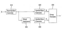
상기 블록 처리기(303)는 입력되는 모바일 서비스 데이터를 다시 G/H(여기서 G<H 임) 부호율로 부호화하여 그룹 포맷터(304)로 출력한다.The
즉, 상기 블록 처리기(303)는 바이트 단위로 입력되는 모바일 서비스 데이터를 비트로 구분하고, 구분된 G 비트를 H 비트로 부호화한 후 바이트 단위로 변환하여 출력한다. 일 예로 입력 데이터 1비트를 2비트로 부호화하여 출력한다면 G=1, H=2가 되고, 입력 데이터 1비트를 4비트로 부호화하여 출력한다면 G=1, H=4가 된다. 본 발명에서는 설명의 편의를 위해 전자를 1/2 부호율의 부호화(또는 1/2 부호화라 하기도 함)라 하고, 후자를 1/4 부호율의 부호화(또는 1/4 부호화라 하기도 함)라 한다.That is, the
여기서 1/4 부호화를 사용하는 경우는 1/2 부호화에 비해서 높은 부호율 때문에 높은 에러 정정 능력을 가질 수가 있다. 이런 이유 때문에 후단의 그룹 포맷터(304)에서 1/4 부호율로 부호화된 데이터는 수신 성능이 떨어질 수 있는 영역에 할당하고, 1/2 부호율로 부호화된 데이터는 더 우수한 성능을 가질 수 있는 영역에 할당한다고 가정하면, 그 성능의 차이를 줄이는 효과를 얻을 수가 있게 된다.In the case of using the 1/4 encoding, it is possible to have a high error correction capability because of the higher code rate than the 1/2 encoding. For this reason, the data encoded at the 1/4 code rate in the
이때, 상기 블록 처리기(303)는 전송 파라미터를 담고 있는 시그널링(signaling) 정보도 입력받을 수 있는데, 이 시그널링 정보도 모바일 서비스 데 이터 처리 과정과 동일하게 1/2 부호화 또는 1/4 부호화를 수행한다. 이후 상기 시그널링 정보도 모바일 서비스 데이터로 간주되어 처리된다.In this case, the
한편 상기 그룹 포맷터(304)는 상기 블록 처리기(303)에서 출력되는 모바일 서비스 데이터를 기 정의된 규칙에 따라 형성되는 데이터 그룹 내 해당 영역에 삽입하고, 또한 데이터 디인터리빙과 관련하여 각종 위치 홀더나 기지 데이터(또는 기지 데이터 위치 홀더)도 상기 데이터 그룹 내 해당 영역에 삽입한다.Meanwhile, the
이때 상기 데이터 그룹은 적어도 하나 이상의 계층화된 영역으로 구분할 수 있고, 계층화된 각 영역의 특성에 따라 각 영역에 삽입되는 모바일 서비스 데이터 종류가 달라질 수 있다. 그리고 각 영역은 일 예로 데이터 그룹 내에서 수신 성능을 기준으로 분류할 수 있다. 또한 하나의 데이터 그룹은 필드 동기를 포함하도록 구성할 수 있다.In this case, the data group may be divided into at least one layered area, and the type of mobile service data inserted into each area may vary according to characteristics of each layered area. For example, each region may be classified based on reception performance in a data group. In addition, one data group may be configured to include field synchronization.
본 발명에서는 데이터 디인터리빙 전의 데이터 구성에서 하나의 데이터 그룹을 A,B,C 영역(Region)으로 구분하는 것을 일 실시예로 한다. 이때 상기 그룹 포맷터(304)는 RS 부호화 및 블록 부호화되어 입력되는 모바일 서비스 데이터를 상기 전송 파라미터를 참조하여 해당 영역에 할당할 수 있다.According to an embodiment of the present invention, one data group is divided into A, B, and C regions in the data configuration before data deinterleaving. In this case, the
도 6a는 데이터 인터리빙 후의 데이터들이 구분되어 나열된 형태이고, 도 6b는 데이터 인터리빙 전의 데이터들이 구분되어 나열된 형태를 보여준다. 즉, 도 6a와 같은 데이터 구조가 수신 시스템으로 전송된다.FIG. 6A illustrates a form in which data after data interleaving is listed separately, and FIG. 6B illustrates a form in which data before data interleaving is separately listed. That is, the data structure as shown in FIG. 6A is transmitted to the receiving system.
그리고 도 6a와 같은 구조로 형성된 데이터 그룹이 데이터 디인터리버(305)로 입력된다.The data group formed in the structure shown in FIG. 6A is input to the
도 6a는 데이터 디인터리빙 전의 데이터 구성에서 데이터 그룹을 크게 세 개의 영역(region) 예를 들어, A 영역(Region A), B 영역(Region B), C 영역(Region C)으로 구분하는 예를 보이고 있다.FIG. 6A illustrates an example in which a data group is largely divided into three regions, for example, region A, region B, and region C in the data configuration before data deinterleaving. have.
또한 본 발명은 상기 A 내지 C 영역을 각각 복수개의 하위 영역으로 다시 구분하는 것을 일 실시예로 한다.In the present invention, the A to C regions are divided into a plurality of sub-regions, respectively.
도 6a는 상기 A 영역이 5개의 하위 영역(A1~A5)으로 구분되고, B 영역이 2개의 하위 영역(B1,B2)으로 구분되며, C 영역이 3개의 하위 영역(C1~C3)으로 구분되는 예를 보이고 있다.In FIG. 6A, the A region is divided into five subregions A1 to A5, the B region is divided into two subregions B1 and B2, and the C region is divided into three subregions C1 to C3. An example is shown.
상기 A 내지 C 영역은 데이터 그룹 내에서 비슷한 수신 성능을 갖는 영역을 기준으로 분류하고 있다. 이때 각 영역의 특성에 따라 삽입되는 모바일 서비스 데이터 종류가 달라질 수 있다.The areas A to C are classified based on areas having similar reception performance in the data group. At this time, the type of mobile service data to be inserted may be changed according to the characteristics of each area.
본 발명에서는 메인 서비스 데이터의 간섭 정도를 기준으로 A 내지 C 영역을 나누는 것을 일 실시예로 설명한다.In the present invention, the division of the areas A to C based on the degree of interference of the main service data will be described as an embodiment.
여기서, 상기 데이터 그룹을 다수개의 영역으로 구분하여 사용하는 이유는 각각의 용도를 달리하기 위해서이다. 즉, 메인 서비스 데이터의 간섭이 없거나 적은 영역은 그렇지 않은 영역보다 강인한 수신 성능을 보일 수 있기 때문이다. 또한, 기지 데이터를 데이터 그룹에 삽입하여 전송하는 시스템을 적용하는 경우, 모바일 서비스 데이터에 연속적으로 긴 기지 데이터를 주기적으로 삽입하고자 할 때, 메인 서비스 데이터의 간섭이 없는 영역(예를 들어, A 영역)에는 일정 길이의 기지 데이터를 주기적으로 삽입하는 것이 가능하다. 그러나 메인 서비스 데이터의 간섭 이 있는 영역(예를 들어, B,C 영역)에는 서비스 메인 서비스 데이터의 간섭으로 기지 데이터를 주기적으로 삽입하는 것이 곤란하고 연속적으로 긴 기지 데이터를 삽입하는 것도 곤란하다.The reason why the data group is divided into a plurality of regions is to differentiate each use. That is, a region where there is no interference of the main service data or a region where there is no interference can show robust reception performance than the region where no interference occurs. In addition, when a system for inserting and transmitting known data into a data group is applied, when it is desired to periodically insert consecutive long known data into mobile service data, an area without interference of main service data (for example, ), It is possible to periodically insert known data of a predetermined length. However, it is difficult to periodically insert known data into the area where the main service data interferes (for example, B and C areas) due to the interference of the service main service data, and also to insert long known data continuously.
다음은 도 6a를 참조하여 데이터 그룹 내에서 A(A1~A5), B(B1,B2), C(C1~C3) 영역이 할당되는 구체적인 예를 설명한다. 도 6a의 데이터 그룹의 크기, 데이터 그룹 내 계층화된 영역의 수와 각 영역의 크기, 계층화된 각 영역에 삽입 가능한 모바일 서비스 데이터 바이트 수 등은 본 발명을 기술하기 위한 하나의 실시예이다.Next, a specific example in which the areas A (A1 to A5), B (B1 and B2), and C (C1 to C3) are allocated in the data group will be described with reference to FIG. 6A. The size of the data group of FIG. 6A, the number of layered regions and the size of each region in the data group, the number of mobile service data bytes that can be inserted into each layered region, and the like are one embodiment for describing the present invention.
이때 상기 그룹 포맷터(304)에서는 필드 동기가 삽입될 위치를 포함하여 데이터 그룹을 형성함으로써, 아래에 설명하는 것과 같이 데이터 그룹을 구성할 수가 있다.In this case, the
즉, 상기 A 영역은 상기 데이터 그룹 내 긴 기지 데이터 열(sequence)이 주기적으로 삽입될 수 있는 영역이면서, 메인 서비스 데이터가 섞이지 않는 영역을 포함한다(예, A2~A5). 또한 상기 A 영역은 상기 데이터 그룹에 삽입될 필드 동기 영역과 첫 기지 데이터 열이 삽입될 영역 사이에 있는 영역(예, A1)을 포함한다. 상기 필드 동기 영역은 ATSC에 존재하는 한 세그먼트 길이(즉, 832 심볼)를 갖는다.That is, the A area is an area where a long known data sequence in the data group can be periodically inserted, and includes an area in which main service data is not mixed (for example, A2 to A5). The area A includes an area (for example, A1) between the field sync area to be inserted in the data group and the area where the first known data sequence is to be inserted. The field sync area has a segment length (i.e., 832 symbols) existing in the ATSC.
일 실시예로 도 6a에서 A1 영역에는 2428 바이트, A2 영역에는 2580 바이트, A3 영역에는 2772 바이트, A4 영역에는 2472 바이트, A5 영역에는 2772 바이트의 모바일 서비스 데이터를 삽입할 수 있다. 상기 모바일 서비스 데이터에서 트렐리스 초기화나 기지 데이터, MPEG 헤더, RS 패리티 등은 제외된다.As an example, in FIG. 6A, mobile service data of 2428 bytes in an A1 area, 2580 bytes in an A2 area, 2772 bytes in an A3 area, 2472 bytes in an A4 area, and 2772 bytes in an A5 area may be inserted. In the mobile service data, the trellis initialization, the known data, the MPEG header, and the RS parity are excluded.
상기와 같이 앞뒤로 기지 데이터 열을 갖는 A 영역의 경우, 수신 시스템에서는 기지 데이터나 필드 동기로부터 얻을 수 있는 채널 정보를 이용하여 등화를 수행할 수 있으므로, 강인한 등화 성능을 얻을 수가 있다.In the case of the A region having the known data streams as described above, the receiving system can perform equalization using channel information obtained from the known data or the field synchronization, so that robust equalization performance can be obtained.
상기 B 영역은 상기 데이터 그룹 내 필드 동기 영역의 앞쪽 8 세그먼트 이내에 위치하는 영역(시간적으로 A1 영역의 앞에 위치함)(예, B1 영역)과, 상기 데이터 그룹에 삽입되는 가장 마지막 기지 데이터 열 다음 8 세그먼트 내에 위치하는 영역(시간적으로 A 영역의 뒤에 위치함)(예, B2 영역)을 포함한다. 예를 들어, 상기 B1 영역에는 930 바이트, B2 영역에는 1350 바이트의 모바일 서비스 데이터를 삽입할 수 있다. 마찬가지로, 상기 모바일 서비스 데이터에서 트렐리스 초기화나 기지 데이터, MPEG 헤더, RS 패리티 등은 제외된다.(For example, B1 area) located in the
상기 B 영역의 경우, 수신 시스템에서는 필드 동기 구간에서 얻어진 채널 정보를 사용하여 등화를 수행할 수 있고, 또한 상기 마지막 기지 데이터 열로부터 얻을 수 있는 채널 정보를 사용하여 등화를 수행할 수 있으므로, 채널의 변화에 대응할 수가 있다.In the case of the B region, since the receiving system can perform equalization using the channel information obtained in the field synchronization period and perform equalization using the channel information obtained from the last known data stream, You can respond to changes.
상기 C 영역은 필드 동기 영역의 앞쪽 9번째 세그먼트를 포함하여 그 앞쪽으로 30 세그먼트 내에 위치하는 영역(시간적으로 A 영역의 앞에 위치함)(예, C1 영역), 상기 데이터 그룹 내 마지막 기지 데이터 열 다음 9번째 세그먼트를 포함한 12 세그먼트 내에 위치하는 영역(시간적으로 A 영역의 뒤에 위치함)(예, C2 영역), 및 상기 C2 영역 다음에 오는 32 세그먼트 내에 위치하는 영역(예, C3 영역)을 포함한다.The C region includes a preceding 9th segment of the field sync area and is located within 30 segments ahead of it (temporally located in front of the A region) (e.g., C1 region) (E.g., C2 region) located within 12 segments including the ninth segment (temporally behind the A region), and an area located within the 32 segments following the C2 region (e.g., the C3 region) .
예를 들어, 상기 C1 영역에는 1272 바이트, C2 영역에는 1560 바이트, C3 영역에는 1312 바이트의 모바일 서비스 데이터를 삽입할 수 있다. 마찬가지로, 상기 모바일 서비스 데이터에서 트렐리스 초기화나 기지 데이터, MPEG 헤더, RS 패리티 등은 제외된다.For example, mobile service data of 1272 bytes in the C1 area, 1560 bytes in the C2 area, and 1312 bytes in the C3 area can be inserted. Similarly, in the mobile service data, the trellis initialization, the known data, the MPEG header, and the RS parity are excluded.
이때 상기 A 영역보다 시간적으로 앞에 위치한 C 영역(예, C1 영역)은 제일 가까운 기지 데이터인 필드 동기에서도 꽤 멀리 떨어져 있기 때문에, 수신 시스템에서 채널 등화시에 필드 동기로부터 얻은 채널 정보를 사용할 수도 있고, 또는 이전 데이터 그룹의 가장 최근의 채널 정보를 사용할 수도 있다. 그리고 상기 A 영역보다 시간적으로 뒤에 위치한 C 영역(예, C2,C3 영역)은 수신 시스템에서 채널 등화시에 상기 마지막 기지 데이터 열에서 얻은 채널 정보를 사용하여 등화를 하더라도 채널이 빠르게 변하는 경우에는 등화가 완벽하게 되지 않을 수가 있다. 그러므로 상기 C 영역은 B 영역보다 등화 성능이 떨어질 수가 있다.At this time, since the C region (for example, the C1 region) located temporally before the A region is considerably far away from the field synchronization which is the nearest known data, the channel information obtained from the field synchronization at the time of channel equalization in the receiving system may be used, Or the latest channel information of the previous data group may be used. The C region (for example, the C2 and the C3 region) located temporally behind the A region is used for equalization when the channel is equalized using the channel information obtained from the last known data sequence at the time of channel equalization in the receiving system It may not be perfect. Therefore, the C region may have less equalization performance than the B region.
상기와 같이 데이터 그룹을 다수개의 계층화된 영역으로 할당한다고 가정하면, 전술한 블록 처리기(303)에서는 계층화된 영역의 특성에 따라 각 영역에 삽입될 모바일 서비스 데이터를 다른 부호율로 부호화할 수도 있다.Assuming that a data group is allocated to a plurality of layered areas as described above, the above-described
예를 들어, 상기 A 영역 내 A1~A5 영역에 삽입될 모바일 서비스 데이터는 블록 처리기(303)에서 1/2 부호율로 부호화를 수행하도록 하고, 이렇게 부호화된 모바일 서비스 데이터를 상기 그룹 포맷터(304)에서 상기 A1~A5 영역에 삽입하도록 할 수 있다.For example, the mobile service data to be inserted into areas A1 to A5 in the area A is encoded by the
상기 B 영역 내 B1,B2 영역에 삽입될 모바일 서비스 데이터는 블록 처리 기(303)에서 1/2 부호율보다 에러 정정 능력이 높은 1/4 부호율로 부호화를 수행하도록 하고, 이렇게 부호화된 모바일 서비스 데이터를 상기 그룹 포맷터(304)에서 상기 B1,B2 영역에 삽입하도록 할 수 있다.The mobile service data to be inserted into the B1 and B2 areas in the B area is encoded by the
상기 C 영역 내 C1~C3 영역에 삽입될 모바일 서비스 데이터는 블록 처리기(303)에서 1/4 부호율이나 또는 1/4 부호율보다 더 강력한 에러 정정 능력을 갖는 부호율로 부호화를 수행하도록 하고, 이렇게 부호화된 데이터를 상기 그룹 포맷터(304)에서 상기 C1~C3 영역에 삽입하도록 할 수도 있고, 추후의 사용을 위해서 미사용(reserve) 영역으로 남겨둘 수도 있다.The mobile service data to be inserted in the C1 to C3 areas of the C region is encoded by the
또한 상기 그룹 포맷터(304)에서는 모바일 서비스 데이터와는 별도로 전체적인 송신 정보를 알려주는 시그널링(signaling)과 같은 부가 정보 데이터도 상기 데이터 그룹 내에 삽입한다.In addition, the
그리고 상기 그룹 포맷터(304)에서는 블록 처리기(303)에서 출력된 부호화된 모바일 서비스 데이터들 외에도 도 6a에서 보이는 것과 같이 후단의 데이터 디인터리빙과 관련하여 MPEG 헤더 위치 홀더, 비체계적 RS 패리티 위치 홀더, 메인 서비스 데이터 위치 홀더를 삽입한다. 여기서 메인 서비스 데이터 위치 홀더를 삽입하는 이유는 도 6a와 같이 데이터 디인터리버의 입력을 기준으로 B,C 영역에서는 모바일 서비스 데이터와 메인 서비스 데이터가 사이사이에 섞이게 되기 때문이다. 일 예로 상기 MPEG 헤더를 위한 위치 홀더는 상기 데이터 디인터리빙 후의 출력 데이터를 기준으로 볼 때, 각 패킷의 제일 앞에 할당될 수 있다.In addition to the encoded mobile service data output from the
또한 상기 그룹 포맷터(304)에서는 기 정해진 방법에 의해서 발생된 기지 데 이터를 삽입하거나 기지 데이터를 추후에 삽입하기 위한 기지 데이터 위치 홀더를 삽입한다. 더불어서 트렐리스 부호화부(Trellis Encoding Module)(256)의 초기화를 위한 위치 홀더를 해당 영역에 삽입한다. 일 실시예로, 상기 초기화 데이터 위치 홀더는 상기 기지 데이터 열의 앞에 삽입할 수 있다.The
이때 하나의 데이터 그룹에 삽입 가능한 모바일 서비스 데이터 사이즈는 해당 데이터 그룹에 삽입되는 트렐리스 초기화 위치 홀더나 기지 데이터(또는 기지 데이터 위치 홀더), MPEG 헤더 위치 홀더, RS 패리티 위치 홀더등의 사이즈에 의해 달라질 수 있다.At this time, the mobile service data size that can be inserted into one data group is determined by the size of the trellis initialization position holder, known data (or known data location holder), MPEG header location holder, RS parity location holder, It can be different.
상기 그룹 포맷터(304)의 출력은 데이터 인터리버(305)로 입력되고, 상기 데이터 디인터리버(305)는 상기 그룹 포맷터(304)에서 출력되는 데이터 그룹 내 데이터 및 위치 홀더를 데이터 인터리빙의 역과정으로 디인터리빙하여 패킷 포맷터(306)로 출력한다. 즉, 도 6a와 같은 형태로 구성된 데이터 그룹 내 데이터 및 위치 홀더가 상기 데이터 디인터리버(305)에서 디인터리빙되면 패킷 포맷터(306)로 출력되는 데이터 그룹은 도 6b와 같은 구조를 갖게 된다.The output of the
상기 패킷 포맷터(306)는 디인터리빙되어 입력된 데이터 중에서 디인터리빙을 위해 할당되었던 메인 서비스 데이터 위치 홀더와 RS 패리티 위치 홀더를 제거하고, 나머지 부분들을 모은 후, 4바이트의 MPEG 헤더 위치 홀더에 널 패킷 PID(또는 메인 서비스 데이터 패킷에서 사용하지 않는 PID)를 갖는 MPEG 헤더를 대체하여 삽입한다.The
또한 상기 패킷 포맷터(306)는 상기 그룹 포맷터(304)에서 기지 데이터 위치 홀더를 삽입한 경우 상기 기지 데이터 위치 홀더에 실제 기지 데이터를 삽입할 수도 있고, 또는 나중에 대체 삽입하기 위하여 상기 기지 데이터 위치 홀더를 조정없이 그대로 출력할 수도 있다.The
그리고 나서 상기 패킷 포맷터(306)는 상기와 같이 패킷 포맷팅된 데이터 그룹 내 데이터들을 188바이트 단위의 모바일 서비스 데이터 패킷(즉, MPEG TS 패킷)으로 구분하여 패킷 다중화기(240)에 제공한다.The
상기 패킷 다중화기(240)는 상기 전처리기(230)에서 출력되는 모바일 서비스 데이터 패킷과 패킷 지터 경감기(220)에서 출력되는 메인 서비스 데이터 패킷을 기 정의된 다중화 방법에 따라 다중화하여 후처리기(Post-Processor)(250)의 데이터 랜더마이저(251)로 출력한다. 상기 다중화 방법은 시스템 설계의 여러 변수들에 의해서 조정이 가능하다.The
상기 패킷 다중화기(240)의 다중화 방법 중 하나로서, 시간축 상으로 버스트(burst) 구간을 두고, 버스트 구간 내 버스트 온 구간에서는 다수개의 데이터 그룹을 전송하고 버스트 오프 구간에서는 메인 서비스 데이터만을 전송하도록 할 수 있다. 여기서 버스트 구간은 현재 버스트의 시작에서 다음 버스트의 시작까지를 의미한다.As one of multiplexing methods of the
이때 상기 버스트 온 구간에서는 메인 서비스 데이터를 전송할 수도 있다. 상기 패킷 다중화기(240)는 상기 전송 파라미터 예를 들어, 버스트 사이즈나 버스트 주기 등의 정보를 참조하여 하나의 버스트에 포함되는 데이터 그룹의 개수, 주기 등을 알 수 있다.In this case, the main service data may be transmitted in the burst on period. The
이때 버스트 온 구간에서는 모바일 서비스 데이터 및 메인 서비스 데이터가 혼재할 수 있으며, 버스트 오프 구간에서는 메인 서비스 데이터만 존재한다. 따라서 메인 서비스 데이터를 전송하는 메인 서비스 데이터 구간은 버스트 온 구간과 버스트 오프 구간에 모두 존재할 수 있다. 이때 버스트 온 구간 내 메인 서비스 데이터 구간과 버스트 오프 구간에 포함되는 메인 서비스 데이터 패킷 수는 서로 다를 수도 있고, 같을 수도 있다.In this case, the mobile service data and the main service data may be mixed in the burst on section, and only the main service data exists in the burst off section. Therefore, the main service data section for transmitting the main service data may exist in both the burst on section and the burst off section. In this case, the number of main service data packets included in the main service data section and the burst off section in the burst on section may be different or the same.
상기와 같이 모바일 서비스 데이터를 버스트 구조로 전송하게 되면 모바일 서비스 데이터만을 수신하는 수신 시스템에서는 버스트 구간에서만 전원을 온시켜 데이터를 수신하고 그 외 메인 서비스 데이터만 전송되는 구간에서는 전원을 오프시켜 메인 서비스 데이터를 수신하지 않도록 함으로써, 수신 시스템의 소모 전력을 줄일 수가 있다.When the mobile service data is transmitted in the burst structure as described above, the receiving system that receives only the mobile service data receives the data by turning on the power only in the burst period and turns off the power in the period in which only the main service data is transmitted, The power consumption of the receiving system can be reduced.
RS 프레임 구성 및 패킷 다중화에 관련된 구체적인 실시예Specific embodiments related to RS frame configuration and packet multiplexing
다음은 전처리기(230)와 패킷 다중화기(240)의 구체적인 실시예에 대해서 설명한다.Next, specific embodiments of the
본 발명에서는 일 실시예로, RS 프레임 부호기(302)에서 구성되는 RS 프레임의 한 로우의 길이인 N 값을 538로 설정한다.In an embodiment of the present invention, an N value, which is the length of one row of the RS frame configured in the
그러면 상기 RS 프레임 부호기(302)는 538개의 트랜스포트 스트림(TS) 패킷을 입력받아 187 * 538 바이트 크기의 제1 RS 프레임을 구성할 수 있다. 이후 전술한 바와 같이 (235,187)-RS 부호화를 거쳐 235 * 538 바이트 크기의 제2 RS 프레임을 형성하고, 다시 16-비트 CRC 체크섬 생성 과정을 거쳐서 235 * 540 바이트 크기 의 제3 RS 프레임을 형성하게 된다.Then, the
한편 도 6a에서와 같이 데이터 그룹 내 다수개의 영역들 중에서 1/2 부호화를 거친 모바일 서비스 데이터를 삽입하게 될 A 영역 내 A1-A5 영역의 바이트 수를 합치면 13024 바이트(=2428+2580+2772+2472+2772 바이트)이다. 이 경우 1/2 부호화 전의 바이트 수는 6512(=13024/2) 바이트이다.Meanwhile, as shown in FIG. 6A, when the number of bytes of the area A1-A5 in the area A, into which the 1 / 2-encoded mobile service data is to be inserted, is 13024 bytes (= 2428 + 2580 + 2772 + 2472). +2772 bytes). In this case, the number of bytes before 1/2 encoding is 6512 (= 13024/2) bytes.
그리고 1/4 부호화를 거친 모바일 서비스 데이터를 삽입하게 될 B 영역 내 B1,B2 영역의 바이트 수를 합치면 2280(=930+1350) 바이트가 된다. 이 경우 1/4 부호화 전의 바이트 수는 570(=2280/4) 바이트이다.The number of bytes in the B1 and B2 areas in the B area into which the 1 / 4-coded mobile service data is to be inserted is 2280 (= 930 + 1350) bytes. In this case, the number of bytes before 1/4 encoding is 570 (= 2280/4) bytes.
정리하면, 상기 블록 처리기(303)로 7082 바이트의 모바일 서비스 데이터가 입력되면, 이 중 6512 바이트는 1/2 부호화를 통해서 13024 바이트로 확장되고, 570 바이트는 1/4 부호화를 통해서 2280 바이트로 확장되게 한다. 그리고 상기 그룹 포맷터(304)는 13024 바이트로 확장된 모바일 서비스 데이터는 A 영역 내 A1~A5 영역에 삽입하고, 2280 바이트로 확장된 모바일 서비스 데이터는 B 영역 내 B1,B2 영역에 삽입한다.In summary, when 7082 bytes of mobile service data are input to the
이때 상기 블록 처리기(303)로 입력되는 7082 바이트의 모바일 서비스 데이터는 RS 프레임 부호기(302)의 출력과 시그널링 정보로 구분할 수가 있다. 본 발명에서는 7082 바이트 중 7050 바이트는 RS 프레임 부호기(302)의 출력에서 받아들이고, 나머지 32 바이트는 시그널링 정보 데이터를 입력받아 1/2 부호화 또는 1/4 부호화를 수행하는 것을 일 실시예로 한다.In this case, the 7082 bytes of mobile service data input to the
한편 RS 프레임 부호기(302)에서 RS 부호화 및 CRC 부호화를 거친 한 개의 RS 프레임은 235 * 540 바이트 즉, 126900 바이트로 구성이 되어 있다. 이것을 시간축에 대해 7050 바이트 단위로 나누면, 18개의 7050 바이트로 구분된다.On the other hand, one RS frame that has undergone RS coding and CRC coding in the
그리고 상기 RS 프레임 부호기(302)에서 출력되는 7050 바이트 단위의 모바일 서비스 데이터는 32 바이트 단위의 부가 정보 데이터와 합쳐진 후 블록 처리기(303)에서 1/2 부호화 또는 1/4 부호화되어 그룹 포맷터(304)로 출력된다. 상기 그룹 포맷터(304)는 1/2 부호화된 데이터는 A 영역에 삽입하고, 1/4 부호화된 데이터는 B 영역에 삽입한다.The 7050-byte mobile service data output from the
다음은 RS 프레임 부호기(302)에서 RS 프레임을 형성하는데 필요한 N 값을 결정하는 과정을 설명한다.Next, a process of determining an N value required to form an RS frame in the
즉, 상기 RS 프레임 부호기(302)에서 RS 부호화 및 CRC 부호화된 최종 RS 프레임(즉, 제3 RS 프레임) 크기인 235 * (N+2) 바이트는 정수개의 그룹에 할당이 되어야 한다. 이때 단일 데이터 그룹에는 부호화 전을 기준으로 7050 바이트가 할당이 되기 때문에, 235 * (N+2)바이트를 7050(=235*30)으로 나누어 떨어지도록 하면, RS 프레임 부호기(302)의 출력 데이터를 효율적으로 데이터 그룹에 할당하게 할 수가 있다. 본 발명에서는 N+2가 30의 배수가 되도록 N 값을 결정하는 것을 일 실시예로 한다. 본 발명에서는 N 값으로 538을 결정하고, N+2(=540)를 30으로 나누면 18이 된다. 이것은 하나의 RS 프레임 내 모바일 서비스 데이터는 1/2 부호화 또는 1/4 부호화 과정을 거쳐 18개의 데이터 그룹에 나누어 할당됨을 의미한다.That is, 235 * (N + 2) bytes, which are the size of the last RS frame (that is, the third RS frame) RS-coded and CRC-coded in the
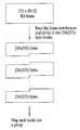
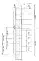
도 7은 본 발명에 따른 RS 프레임의 분할 과정을 도시한 것이다. 즉, 235 * (N+2) 크기를 갖는 RS 프레임을 30*235 바이트 블록으로 나눈다. 그리고 나누어진 각 블록은 하나의 그룹에 매핑된다. 즉, 30*235 바이트 크기를 갖는 하나의 블록의 데이터는 1/2 부호화 또는 1/4 부호화 과정을 거쳐 하나의 데이터 그룹에 삽입된다.7 illustrates a process of dividing an RS frame according to the present invention. That is, an RS frame having a size of 235 * (N + 2) is divided into 30 * 235 byte blocks. Each divided block is mapped to one group. That is, data of one block having a size of 30 * 235 bytes is inserted into one data group through 1/2 encoding or 1/4 encoding.
그리고 상기와 같이 그룹 포맷터(304)에서 계층화된 각 영역에 해당 데이터 및 위치 홀더가 삽입된 데이터 그룹은 데이터 디인터리버(305)와 패킷 포맷터(306)를 거쳐 패킷 다중화기(240)로 입력된다.As described above, the data group in which the corresponding data and the position holder are inserted in each layered area in the
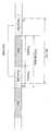
도 8은 본 발명의 구체적인 실시예에 따른 패킷 다중화기(240)의 동작 예를 보인 것이다. 즉, 상기 패킷 다중화기(240)에서는 모바일 서비스 데이터와 메인 서비스 데이터가 섞여 있는 데이터 그룹이 포함된 필드와 메인 서비스 데이터만 있는 필드를 다중화하여 데이터 랜더마이저(251)로 출력한다.8 illustrates an operation of the
이때, 235 * 540 바이트 크기를 갖는 한 개의 RS 프레임을 전송하기 위해서는 18개의 데이터 그룹을 전송해야 한다. 여기서 각 데이터 그룹은 도 6a와 같이 필드 동기를 포함한다. 그러므로 18개의 데이터 그룹은 18 필드 구간 동안 전송되며, 상기 18개의 데이터 그룹이 전송되는 구간을 버스트 온 구간이라 하기로 한다.In this case, in order to transmit one RS frame having a size of 235 * 540 bytes, 18 data groups must be transmitted. Here, each data group includes field synchronization as shown in FIG. 6A. Therefore, 18 data groups are transmitted during 18 field periods, and the period in which the 18 data groups are transmitted will be referred to as a burst on period.
상기 버스트 온 구간 내 각 필드에서는 필드 동기를 포함하는 하나의 데이터 그룹과 메인 서비스 데이터가 다중화되어 출력된다. 일 실시예로 상기 버스트 온 구간 내 각 필드에서는 118 세그먼트 크기의 데이터 그룹과 194 세그먼트 크기의 메인 서비스 데이터가 다중화되어 출력된다.In each field in the burst-on period, one data group including field synchronization and main service data are multiplexed and output. In an embodiment, each field within the burst on period is multiplexed with a data group of 118 segments and main service data of 194 segments.
도 8을 보면, 버스트(burst) 온 구간 동안 즉, 18 필드 구간 동안은 18개의 데이터 그룹이 포함된 필드를 전송하고, 그 다음 버스트 오프 구간 즉, 12 필드 구 간 동안은 메인 서비스 데이터만으로 구성된 필드를 전송하게 된다. 이후 다시 버스트 온 구간에서는 18개의 데이터 그룹이 포함된 18 필드를 전송하고, 다음 버스트 오프 구간에서는 메인 서비스 데이터만으로 구성된 12 필드를 전송한다.Referring to FIG. 8, a field including 18 data groups is transmitted during a burst on period, that is, an 18 field period, and then a field including only main service data during a burst off period, that is, a 12 field period. Will be sent. After that, 18 fields including 18 data groups are transmitted in the burst on period, and 12 fields including only main service data are transmitted in the next burst off period.
그리고 본 발명은 첫번째 18개의 데이터 그룹을 포함한 버스트 온 구간과 두 번째 18개의 데이터 그룹을 포함한 버스트 온 구간에서 같은 종류의 데이터 서비스를 제공할 수도 있고, 서로 다른 데이터 서비스를 전송할 수도 있다.In addition, the present invention may provide the same type of data service or may transmit different data services in the burst on period including the first 18 data groups and the burst on period including the second 18 data groups.
예를 들어, 도 8의 첫 번째 버스트 온 구간과 두 번째 버스트 온 구간에서 서로 다른 데이터 서비스를 전송하고, 수신 시스템에서는 하나의 데이터 서비스만 수신하기를 원한다고 가정하자. 이러한 경우 수신 시스템에서는 원하는 데이터 서비스를 포함하는 해당 버스트 온 구간에서만 전원을 온시켜 18개의 필드를 수신하고, 나머지 42개의 필드 구간 동안에는 전원을 오프시켜 수신하지 않도록 함으로써, 수신 시스템의 소모 전력을 줄일 수 있게 된다. 또한 수신 시스템에서는 하나의 버스트 온 구간에서 수신된 18개의 데이터 그룹으로부터 하나의 RS 프레임을 구성할 수 있으므로 디코딩이 용이해지는 잇점이 있다.For example, suppose that the first burst on period and the second burst on period of FIG. 8 transmit different data services, and the receiving system wants to receive only one data service. In this case, the receiving system can reduce the power consumption of the receiving system by turning on the power only in the corresponding burst on period including the desired data service and receiving 18 fields, and turning off the power for the remaining 42 field periods. Will be. In addition, the receiving system can configure one RS frame from 18 data groups received in one burst-on period, so that decoding is easy.
본 발명에서 하나의 버스트 온 구간에 포함되는 데이터 그룹의 수는 RS 프레임의 크기에 따라 달라지며, 상기 RS 프레임의 크기는 N 값에 따라 달라진다. 즉, N 값을 조정하여 버스트 내 데이터 그룹 수를 조정할 수 있다. 이때 (235,187)-RS 부호화는 고정된 상태에서 상기 N 값을 조정하는 것을 일 실시예로 한다.In the present invention, the number of data groups included in one burst on interval depends on the size of the RS frame, and the size of the RS frame depends on the value of N. That is, the number of data groups in the burst can be adjusted by adjusting the N value. In this case, the (235,187) -RS encoding adjusts the N value in a fixed state.
또한 데이터 그룹 내 삽입 가능한 모바일 서비스 데이터 크기는 해당 데이터 그룹에 삽입되는 트렐리스 초기화나 기지 데이터, MPEG 헤더, RS 패리티 등의 크 기에 의해 달라질 수 있다.In addition, the size of the mobile service data that can be inserted in the data group may vary depending on the trellis initialization, known data, MPEG header, RS parity, etc. inserted into the data group.
한편 상기 패킷 다중화 과정에서 메인 서비스 데이터 사이사이에 모바일 서비스 데이터를 포함하는 데이터 그룹이 다중화되기 때문에 메인 서비스 데이터 패킷의 시간적인 위치가 상대적으로 이동하게 된다. 그리고 수신 시스템의 메인 서비스 데이터 처리를 위한 시스템 목표 디코더(즉, MPEG 디코더)에서는 메인 서비스 데이터만을 수신하여 복호하고 모바일 서비스 데이터 패킷은 널 데이터 패킷으로 인식하여 버리게 된다.Meanwhile, since the data group including the mobile service data is multiplexed between the main service data in the packet multiplexing process, the temporal position of the main service data packet is relatively moved. The system target decoder (i.e., MPEG decoder) for main service data processing of the receiving system receives and decodes only main service data and recognizes the mobile service data packet as a null data packet.
따라서 수신 시스템의 시스템 목표 디코더가 데이터 그룹과 다중화된 메인 서비스 데이터 패킷을 수신할 경우 패킷 지터가 발생하게 된다.Therefore, packet jitter occurs when the system target decoder of the receiving system receives the main service data packet multiplexed with the data group.
이때 상기 시스템 목표 디코더에서는 비디오 데이터를 위한 여러 단계의 버퍼가 존재하고 그 사이즈가 상당히 크기 때문에 상기 패킷 다중화기(240)에서 발생시키는 패킷 지터는 비디오 데이터의 경우, 큰 문제가 되지 않는다. 그러나 시스템 목표 디코더가 가지는, 오디오 데이터를 위한 버퍼의 사이즈는 작기 때문에 문제가 될 수 있다.At this time, since the system target decoder has buffers of various stages for video data and its size is considerably large, the packet jitter generated in the
즉, 상기 패킷 지터로 인해 수신 시스템의 메인 서비스 데이터를 위한 버퍼, 예를 들면 오디오 데이터를 위한 버퍼에서 오버플로우(overflow)나 언더플로우(underflow)가 발생할 수 있다.That is, due to the packet jitter, an overflow or an underflow may occur in a buffer for a main service data of the receiving system, for example, a buffer for audio data.
따라서 패킷 지터 경감기(220)에서는 상기 시스템 목표 디코더의 버퍼에서 오버플로우 또는 언더플로우가 발생하지 않도록 메인 서비스 데이터 패킷의 상대적인 위치를 재조정한다.Therefore, the
본 발명에서는 오디오 버퍼의 동작에 주는 영향을 최소화하기 위하여 메인 서비스 데이터의 오디오 데이터 패킷의 위치를 재배치하는 실시예들을 설명한다. 상기 패킷 지터 경감기(220)는 메인 서비스의 오디오 데이터 패킷이 최대한 균일하게 위치할 수 있도록 메인 서비스 데이터 구간에서 오디오 데이터 패킷을 재배치한다.Embodiments for rearranging the positions of the audio data packets of the main service data in order to minimize the influence on the operation of the audio buffer will be described. The
상기 패킷 지터 경감기(220)에서 메인 서비스의 오디오 데이터 패킷을 재배치하는 기준은 다음과 같다. 이때 상기 패킷 지터 경감기(220)는 후단의 패킷 다중화기(240)의 다중화 정보를 알고 있다고 가정한다.The criterion for relocating the audio data packet of the main service in the
첫번째, 버스트 온 구간 내 메인 서비스 데이터 구간, 예를 들어 두개의 데이터 그룹 사이에 위치하는 메인 서비스 데이터 구간에서 오디오 데이터 패킷이 한 개 존재하는 경우에는 오디오 데이터 패킷을 메인 서비스 데이터 구간의 제일 앞에 배치하고, 2개 존재하는 경우에는 제일 앞과 제일 뒤에 배치하며, 3개 이상 존재하는 경우에는 제일 앞과 제일 뒤에 배치하고 나머지를 그 사이에 균등한 간격으로 배치한다.First, if there is one audio data packet in the main service data section in the burst on section, for example, the main service data section between two data groups, the audio data packet is placed in front of the main service data section. If two are present, they are placed at the front and the rear. If there are three or more, they are placed at the front and the rear and the rest are evenly spaced between them.
두번째, 버스트 온 구간 시작 전의 메인 서비스 데이터 구간 즉, 버스트 오프 구간에서는 제일 마지막 위치에 오디오 데이터 패킷을 배치한다.Second, in the main service data section before the start of the burst on section, that is, the burst off section, the audio data packet is arranged at the last position.
세번째, 버스트 온 구간이 끝난 후 버스트 오프 구간의 메인 서비스 데이터 구간에서는 제일 앞에 오디오 데이터 패킷을 배치한다.Third, the audio data packet is placed first in the main service data section of the burst off section after the burst on section ends.
그리고 오디오 데이터가 아닌 패킷들은 입력되는 순서대로 오디오 데이터 패킷의 위치를 제외한 공간에 배치한다.The packets which are not audio data are arranged in a space excluding the positions of the audio data packets in the input order.
한편 상기와 같이 메인 서비스 데이터 패킷의 위치를 상대적으로 재조정하게 되면 그에 따른 PCR(Program Clock Reference) 값을 수정해 주어야 한다. PCR 값은 MPEG 디코더의 시간을 맞주기 위한 시간 기준값으로 TS 패킷의 특정 영역에 삽입되어 전송되어진다. 상기 패킷 지터 경감기(220)에서 PCR 값 수정의 기능도 수행하는 것을 일 실시예로 한다.Meanwhile, if the position of the main service data packet is relocated as described above, the corresponding PCR (Program Clock Reference) value should be modified accordingly. The PCR value is inserted into a specific area of the TS packet as a time reference value for matching the time of the MPEG decoder and transmitted. The
상기 패킷 지터 경감기(220)의 출력은 패킷 다중화기(240)로 입력된다. 상기 패킷 다중화기(240)는 전술한 바와 같이 패킷 지터 경감기(220)에서 출력되는 메인 서비스 데이터 패킷과 전처리기(230)에서 출력되는 모바일 서비스 데이터 패킷을 기 설정된 다중화 규칙에 따라 버스트 구조로 다중화하여 후 처리기(250)의 데이터 랜더마이저(251)로 출력한다.The output of the
상기 데이터 랜더마이저(251)는 입력된 데이터가 메인 서비스 데이터 패킷이면 기존의 랜더마이저와 동일하게 랜더마이징을 수행한다. 즉, 메인 서비스 데이터 패킷 내 동기 바이트를 버리고 나머지 187 바이트를 내부에서 발생시킨 의사랜덤(pseudo random) 바이트를 사용하여 랜덤하게 만든 후 RS 부호기/비체계적 RS 부호기(252)로 출력한다.If the input data is a main service data packet, the
그러나 입력된 데이터가 모바일 서비스 데이터 패킷이면, 패킷의 일부만을 랜더마이징할 수도 있다. 예를 들어, 상기 전처리기(230)에서 모바일 서비스 데이터에 대해 미리 랜더마이징을 수행하였다고 가정하면, 상기 데이터 랜더마이저(251)는 상기 모바일 서비스 데이터 패킷에 포함된 4바이트의 MPEG 헤더 중 동기 바이트를 버리고 나머지 3바이트에 대해서만 랜더마이징을 수행하여 상기 RS 부호 기/비체계적 RS 부호기(252)로 출력한다. 즉, 상기 MPEG 헤더를 제외한 나머지 모바일 서비스 데이터에 대해서는 랜더마이징을 수행하지 않고 상기 RS 부호기/비체계적 RS 부호기(252)로 출력한다. 상기 데이터 랜더마이저(251)는 모바일 서비스 데이터 패킷에 포함된 기지 데이터(또는 기지 데이터 위치 홀더)와 초기화 데이터 위치 홀더에 대해서는 랜더마이징을 수행할 수도 있고 수행하지 않을 수도 있다.However, if the input data is a mobile service data packet, only a part of the packet may be rendered. For example, assuming that the
상기 RS 부호기/비체계적 RS 부호기(252)는 상기 데이터 랜더마이저(251)에서 랜더마이징되는 데이터 또는 바이패스되는 데이터에 대해 RS 부호화를 수행하여 20바이트의 RS 패리티를 부가한 후 데이터 인터리버(253)로 출력한다. 이때 상기 RS 부호기/비체계적 RS 부호기(252)는 입력된 데이터가 메인 서비스 데이터 패킷인 경우 기존 방송 시스템과 동일하게 체계적 RS 부호화를 수행하여 20바이트의 RS 패리티를 187바이트의 데이터 뒤에 부가한다. 그리고 모바일 서비스 데이터 패킷이면 비체계적 RS 부호화를 수행하고, 이때 얻은 20바이트의 RS 패리티를 패킷 내 미리 정해진 패리티 바이트 위치에 삽입한다.The RS encoder /
상기 데이터 인터리버(253)는 바이트 단위의 길쌈(convolutional) 인터리버이다.The data interleaver 253 is a convolutional interleaver on a byte basis.
상기 데이터 인터리버(253)의 출력은 패리티 치환기(254)와 비체계적 RS 부호기(255)로 입력된다.The output of the data interleaver 253 is input to a
한편 상기 패리티 치환기(254)의 후단에 위치한 트렐리스 부호화부(256)의 출력 데이터를 송/수신측에서 약속에 의해 정의한 기지 데이터로 하기 위해 먼저 트렐리스 부호화부(256) 내의 메모리의 초기화가 필요하다. 즉 입력되는 기지 데이 터 열이 트렐리스 부호화되기 전에 먼저 트렐리스 부호화부(256)의 메모리를 초기화시켜야 한다.On the other hand, in order to make the output data of the
이때 입력되는 기지 데이터 열의 시작 부분은 실제 기지 데이터가 아니라 전처리기(230) 내 그룹 포맷터에서 삽입된 초기화 데이터 위치 홀더이다. 따라서 입력되는 기지 데이터 열이 트렐리스 부호화되기 직전에 초기화 데이터를 생성하여 해당 트렐리스 메모리 초기화 데이터 위치 홀더와 치환하는 과정이 필요하다.At this time, the beginning of the inputted known data sequence is not an actual known data but an initialized data position holder inserted in the group formatter in the
그리고 상기 트렐리스 메모리 초기화 데이터는 상기 트렐리스 부호화부(256)의 메모리 상태에 따라 그 값이 결정되어 생성된다. 또한 치환된 초기화 데이터에 의한 영향으로 RS 패리티를 다시 계산하여 상기 데이터 인터리버(253)에서 출력되는 RS 패리티와 치환하는 과정이 필요하다.The initial value of the trellis memory initialization data is determined according to the memory state of the
따라서 상기 비체계적 RS 부호기(255)에서는 상기 데이터 인터리버(253)로부터 초기화 데이터로 치환될 초기화 데이터 위치 홀더가 포함된 모바일 서비스 데이터 패킷을 입력받고, 트렐리스 부호화부(256)로부터 초기화 데이터를 입력받는다. 그리고 입력된 모바일 서비스 데이터 패킷 중 초기화 데이터 위치 홀더를 초기화 데이터로 치환하고 상기 모바일 서비스 데이터 패킷에 부가된 RS 패리티 데이터를 제거한 후 비체계적인 RS 부호화를 수행한다. 그리고 상기 비체계적 RS 부호화하여 얻은 RS 패리티를 상기 패리티 치환기(255)로 출력한다. 그러면 상기 패리티 치환기(255)는 모바일 서비스 데이터 패킷 내 데이터는 상기 데이터 인터리버(253)의 출력을 선택하고, RS 패리티는 비체계적 RS 부호기(255)의 출력을 선택하여 트렐리스 부호화부(256)로 출력한다.Therefore, the
한편 상기 패리티 치환기(254)는 메인 서비스 데이터 패킷이 입력되거나 또는 치환될 초기화 데이터 위치 홀더가 포함되지 않은 모바일 서비스 데이터 패킷이 입력되면 상기 데이터 인터리버(253)에서 출력되는 데이터와 RS 패리티를 선택하여 그대로 트렐리스 부호화부(256)로 출력한다.Meanwhile, the
상기 트렐리스 부호화부(256)는 바이트 단위의 데이터를 심볼 단위로 바꾸고 12-way 인터리빙하여 트렐리스 부호화한 후 동기 다중화기(260)로 출력한다.The
상기 동기 다중화기(260)는 트렐리스 부호화부(256)의 출력에 필드 동기와 세그먼트 동기를 삽입하여 송신부(270)의 파일롯 삽입기(271)로 출력한다.The
상기 파일롯 삽입기(271)에서 파일롯이 삽입된 데이터는 변조기(272)에서 기 설정된 변조 방식 예를 들어, VSB 방식으로 변조된 후 RF 업 컨버터(273)를 통해 각 수신 시스템으로 전송된다.The pilot inserted data in the
블록 처리기Block processor
도 9는 본 발명의 일 실시예에 따른 블록 처리기의 상세 블록도로서, 바이트-비트 변환기(401), 심볼 부호기(402), 심볼 인터리버(403), 및 심볼-바이트 변환기(404)를 포함할 수 있다.9 is a detailed block diagram of a block processor according to an embodiment of the present invention, which may include a byte-
상기 바이트-비트 변환기(401)는 상기 RS 프레임 부호기(112)에서 입력되는 모바일 서비스 데이터 바이트를 비트로 구분하여 심볼 부호기(402)로 출력한다.The byte-
상기 바이트-심볼 변환기(401)는 전송 파라미터 등을 담고있는 시그널링(signaling) 정보도 입력받을 수 있으며, 이 시그널링 정보 바이트들도 비트로 구분하여 심볼 부호기(402)로 출력한다. 여기서 상기 전송 파라미터를 담고 있는 시그널링 정보는 모바일 서비스 데이터 처리 과정과 동일하게 데이터 랜더마이저(301)와 RS 프레임 부호기(302)를 거쳐 블록 처리기(303)로 입력될 수도 있고, 또는 상기 데이터 랜더마이저(301)와 RS 프레임 부호기(302)를 거치지 않고 바로 블록 처리기(303)로 입력될 수도 있다.The byte-
상기 심볼 부호기(402)는 입력되는 데이터 G비트를 H비트로 부호화하여 출력하는 G/H 부호기이다.The
본 발명에서는 일 실시예로, 상기 심볼 부호기(402)는 1/2 부호율의 부호화(또는 1/2 부호화라 하기도 함) 또는 1/4 부호율의 부호화(또는 1/4 부호화라 하기도 함)를 수행한다고 가정한다. 상기 심볼 부호기(402)는 입력받은 모바일 서비스 데이터들과 시그널링 정보에 대해 1/2 부호화 또는 1/4 부호화를 수행한다. 이후 상기 시그널링 정보도 모바일 서비스 데이터로 간주되어 처리된다.In one embodiment of the present invention, the
상기 심볼 부호기(402)에서는 1/2 부호화인 경우에는 1비트를 입력받아 2비트(즉, 1개의 심볼)로 부호화하여 출력하고, 1/4 부호화인 경우에는 1비트를 입력받아 4비트(즉, 2개의 심볼)로 부호화하여 출력한다.The
도 10은 상기 심볼 부호기(402)의 일 실시예를 보인 상세 블록도로서, 2개의 지연기(501,503)와 3개의 가산기(502,504,505)로 구성되어, 입력 데이터 비트 U를 부호화하여 4비트(u0~u3)로 출력한다. 이때 상기 데이터 비트 U는 최상위 비트 u0로 그대로 출력됨과 동시에 부호화되어 하위 비트 u1u2u3로 출력된다.FIG. 10 is a detailed block diagram showing an embodiment of the
즉, 입력 데이터 비트 U는 그대로 최상위 비트 u0로 출력됨과 동시에 제1,제3 가산기(502,505)로 출력된다. 상기 제1 가산기(502)는 입력 데이터 비트 U와 제1 지연기(501)의 출력을 더하여 제2 지연기(503)로 출력하며, 상기 제2 지연기(502)에서 일정 시간(예를 들어 1 클럭) 지연된 데이터는 하위 비트 u1로 출력됨과 동시에 제1 지연기(501)로 피드백된다. 상기 제1 지연기(501)는 상기 제2 지연기(502)에서 피드백되는 데이터를 일정 시간(예를 들어, 1 클럭) 지연시켜 제1 가산기(502)와 제 2 가산기(504)로 출력한다. 상기 제2 가산기(504)는 제1,제2 지연기(501,503)의 출력을 더하여 하위 비트 u2로 출력한다. 상기 제3 가산기(505)는 입력 데이터 비트 U와 제2 가산기(504)의 출력을 더하여 하위 비트 u3으로 출력한다.That is, the input data bits U are output as they are as most significant bits u0 and output to the first and
이때 상기 심볼 부호기(402)는 입력 데이터 비트 U가 1/2 부호율로 부호화될 데이터라면 4개의 출력 비트 u0u1u2u3 중 u0u1 비트로 한 심볼을 구성하여 출력하면 된다. 또한 1/4 부호율로 부호화될 데이터라면 u0u1 비트로 구성된 심볼을 출력하고, 이어 u2u3 비트로 된 또 다른 심볼을 출력하면 된다. 다른 실시예로, 1/4 부호율로 부호화될 데이터라면 u0u1 비트로 구성된 심볼을 두 번 반복하여 출력할 수도 있다.In this case, if the input data bit U is data to be encoded at a 1/2 code rate, the
또 다른 실시예로, 상기 심볼 부호기(402)에서는 4개의 출력 비트 u0u1u2u3을 모두 출력하고, 후단의 심볼 인터리버(403)에서 1/2 부호율인 경우에는 4개의 출력 비트 u0u1u2u3 중 u0u1 비트로 구성된 심볼만을 선택하고, 1/4 부호율인 경우에는 u0u1 비트로 구성된 심볼과 u2u3 비트로 구성된 또 다른 심볼을 모두 선택하도록 설계할 수도 있다. 또 다른 실시예로, 1/4 부호율인 경우에는 u0u1 비트로 구성된 심볼을 반복하여 선택하도록 할 수도 있다.In another embodiment, the
상기 심볼 부호기(402)의 출력은 심볼 인터리버(403)로 입력되고, 상기 심볼 인터리버(403)는 상기 심볼 부호기(402)의 출력 데이터에 대해 심볼 단위로 블록 인터리빙을 수행한다.The output of the
상기 심볼 인터리버(403)는 구조적으로 어떤 순서 재배열을 하는 인터리버이면 어느 인터리버라도 적용될 수 있다. 하지만, 본 발명에서는 순서를 재배열하려는 심볼의 길이가 다양한 경우에도 적용 가능한 가변 길이 심볼 인터리버를 사용하는 것을 일 실시예로 설명한다.The symbol interleaver 403 may be applied to any interleaver as long as it is an interleaver structurally performing any order rearrangement. However, according to an embodiment of the present invention, a variable length symbol interleaver applicable even when the length of symbols to be rearranged is various will be described.
도 11은 본 발명에 따른 심볼 인터리버의 일 실시예를 보인 도면으로서, 순서를 재배열하려는 심볼의 길이가 다양한 경우에도 적용 가능한 가변 길이 심볼 인터리버이다.FIG. 11 is a diagram illustrating an embodiment of a symbol interleaver according to the present invention, and is a variable length symbol interleaver applicable even when a length of symbols to be rearranged is varied.
특히 도 11은 K=6, L=8인 경우의 심볼 인터리버의 예를 보이고 있다. 상기 K는 심볼 부호기(402)에서 심볼 인터리빙을 위해 출력되는 심볼들의 개수이고, L은 심볼 인터리버(403)에서 실제로 인터리빙이 되는 심볼들의 개수이다.In particular, FIG. 11 shows an example of a symbol interleaver when K = 6 and L = 8. K is the number of symbols output for symbol interleaving in the
본 발명의 심볼 인터리버(403)는 L = 2n(여기서 n은 자연수)이면서 L ≥ K 조건을 만족하여야 한다. 만일 K와 L의 값이 차이가 나게 되면, 차이나는 개수(=L-K)만큼 널(null 또는 dummy) 심볼이 추가되어 인터리빙 패턴이 만들어진다.The symbol interleaver 403 of the present invention must satisfy the condition L ≥ K while L = 2n (where n is a natural number). If the values of K and L are different, an interleaving pattern is created by adding null or dummy symbols by the number of differences (= LK).
그러므로 상기 K는 인터리빙을 위해 상기 심볼 인터리버(403)로 입력되는 실제 심볼들의 블록 크기가 되고, L은 상기 심볼 인터리버(403)에서 생성된 인터리빙 패턴에 의해 인터리빙이 이루어지는 인터리빙 단위가 된다.Therefore, K is a block size of actual symbols input to the
도 11은 그 예를 보인 것으로서, 인터리빙하기 위해 심볼 부호기(402)에서 출력되는 심볼의 수(=K)는 6 심볼이고, 실제 인터리빙 단위(L)는 8 심볼이 된다. 따라서 도 11의 (a)와 같이 2 심볼이 널 심볼로 추가되어 인터리빙 패턴이 만들어진다.FIG. 11 shows an example, and the number of symbols (= K) output from the
하기의 수학식 2는 상기 심볼 인터리버(403)에서 순서를 재배열하고자 하는 심볼 K개를 순서대로 입력받은 후, L = 2n이면서 L ≥ K 조건을 만족하는 L을 찾아 인터리빙 패턴을 만들어 재배열하는 과정을 수학식으로 표현한 것이다.
P(i) = { S x i x (i+1) / 2 } mod LP (i) = {S x i x (i + 1) / 2} mod L
여기서 L ≥ K , L = 2n이고, n, S는 자연수이다. 도 11에서 S는 89, L은 8로 가정하고, 구현한 인터리빙 패턴 및 인터리빙 예이다.Where L ≧ K and L = 2n , where n and S are natural numbers. In FIG. 11, S is 89 and L is 8.
상기 수학식 2, 도 11의 (b)와 같이 L 심볼 단위로 K개의 입력 심볼과 (L-K)개의 널 심볼의 순서를 재배열한 후 하기의 수학식 3, 도 11의 (c)와 같이 널 심볼의 위치를 제거하고 다시 정렬하며, 정렬된 순서대로 인터리빙된 심볼을 심볼-바이트 변환기(404)로 출력된다.After rearranging the order of the K input symbols and the (LK) null symbols in units of L symbols as shown in
상기 심볼-바이트 변환기(404)는 상기 심볼 인터리버(403)에서 순서 재배열 이 완료되어 출력되는 모바일 서비스 데이터 심볼들을 바이트로 변환하여 그룹 포맷터(304)로 출력한다.The symbol-
도 12a는 본 발명의 다른 실시예에 따른 블록 처리기의 상세 블록도로서, 인터리빙부(Interleaving nit)(610), 및 블록 포맷터(block formatter)(620)를 포함할 수 있다.12A is a detailed block diagram of a block processor according to another embodiment of the present invention, and may include an
상기 인터리빙부(610)는 바이트-심볼 변환기(converter)(611), 심볼-바이트 변환기(612), 심볼 인터리버(613), 및 심볼-바이트 변환기(614)를 포함할 수 있다. 상기 심볼 인터리버는 블록 인터리버라 하기도 한다.The
상기 인터리빙부(610)의 바이트-심볼 변환기(611)는 상기 RS 프레임 부호기(302)에서 바이트 단위로 출력되는 모바일 서비스 데이터(X)를 심볼 단위로 변환하여 심볼-바이트 변환기(612)와 심볼 인터리버(613)로 출력한다. 즉, 상기 바이트-심볼 변환기(611)는 입력되는 모바일 서비스 데이터 바이트(=8비트)의 2비트를 1개의 심볼로 하여 출력한다. 이는 트렐리스 부호화부(256)의 입력이 2비트로 된 심볼 단위이기 때문이다. 상기 블록 처리기(303)와 트렐리스 부호화부(256)와의 관계는 뒤에서 설명한다.Bytes of the
이때 상기 바이트-심볼 변환기(611)는 전송 파라미터 등을 담고 있는 시그널링(signaling) 정보도 입력받을 수 있으며, 이 시그널링 정보 바이트들도 심볼 단위로 구분하여 심볼-바이트 변환기(612)와 심볼 인터리버(613)로 출력한다.In this case, the byte-
상기 심볼-바이트 변환기(612)는 상기 바이트-심볼 변환기(611)에서 출력되는 4개의 심볼을 모아 바이트를 구성한 후 블록 포맷터(620)로 출력한다. 이때 상 기 심볼-바이트 변환기(612)와 상기 바이트-심볼 변환기(611)는 서로 역의 과정이기 때문에 두 블록의 결과는 상쇄되어 도 12b에서와 같이 입력 데이터 X가 그대로 블록 포맷터(620)로 바이패스되는 효과가 있다. 즉, 도 12b의 인터리빙부(610)는 도 12a의 인터리빙부(610)와 등가적인 구조를 가지므로, 동일한 부호를 사용한다.The symbol-
상기 심볼 인터리버(613)는 상기 바이트-심볼 변환기(611)에서 출력되는 데이터에 대해 심볼 단위로 블록 인터리빙을 수행하여 심볼-바이트 변환기(614)로 출력한다.The symbol interleaver 613 performs block interleaving on a symbol-by-symbol basis for the data output from the byte-
상기 심볼 인터리버(613)는 구조적으로 순서 재배열을 하는 인터리버이면 어떠한 인터리버라도 적용될 수 있다. 본 발명에서는 순서를 재배열하려는 심볼의 길이가 다양한 경우에도 적용 가능한 가변 길이 인터리버를 사용하는 것을 일 실시예로 한다. 예를 들면, 도 12a, 도 12b에서도 도 11의 심볼 인터리버를 적용할 수 있다.The symbol interleaver 613 may be applied to any interleaver as long as the interleaver is structurally rearranged. According to an embodiment of the present invention, a variable length interleaver may be used even when the length of a symbol to be rearranged is various. For example, the symbol interleaver of FIG. 11 may also be applied to FIGS. 12A and 12B.
상기 심볼-바이트 변환기(614)는 상기 심볼 인터리버(613)에서 순서 재배열이 완료되어 출력되는 모바일 서비스 데이터 심볼들을 모아 바이트를 구성한 후 블록 포맷터(620)로 출력한다. 즉, 상기 심볼-바이트 변환기(614)는 상기 심볼 인터리버(613)에서 출력되는 4개의 심볼을 모아 바이트를 구성한다.The symbol-
상기 블록 포맷터(620)는 도 13과 같이 각 심볼-바이트 변환기(612,614)의 출력을 블록 내에서 일정 기준에 따라 배열하는 역할을 수행한다. 이때 상기 블록 포맷터(620)는 트렐리스 부호화부(256)와 관계되어 동작한다.The
즉, 상기 블록 포맷터(620)는 상기 트렐리스 부호화부(256)로 입력되는 메인 서비스 데이터, 기지 데이터, RS 패리티 데이터, MPEG 헤더 데이터 등 모바일 서비스 데이터를 제외한 나머지 데이터들의 위치(또는 순서)를 고려하여 각 심볼-바이트 변환기(612,614)의 모바일 서비스 데이터 출력 순서를 결정한다.That is, the
상기 트렐리스 부호화부(256)는 일 실시예로서, 내부에 12개의 트렐리스 부호기를 구비하고 있다.The
도 14는 본 발명의 일 실시예에 따른 트렐리스 부호화부(256)의 상세 블록도로서, 12개의 동일한 트렐리스 부호기가 노이즈 분산을 위해 인터리버로 결합되는 예를 보이고 있다. 상기 각 트렐리스 부호기는 프리코더(Pre coder)를 포함할 수 있다.14 is a detailed block diagram of a
도 15a는 상기 블록 처리기(303)와 트렐리스 부호화부(256)가 연접(concatenation)된 모습을 도시하고 있다. 실제로 송신 시스템에서는 도 3과 같이 블록 처리기(303)를 포함하는 전처리기(230)와 트렐리스 부호화부(256) 사이에 다수의 블록이 존재하지만, 수신 시스템에서는 두 블록이 연접된 것으로 간주하여 복호를 수행하게 된다.FIG. 15A illustrates a state in which the
그런데 상기 트렐리스 부호화부(256)로 입력되는 메인 서비스 데이터, 기지 데이터, RS 패리티 데이터, MPEG 헤더 데이터 등 모바일 서비스 데이터를 제외한 데이터들은 상기 블록 처리기(303)와 트렐리스 부호화부(256) 사이에 존재하는 블록들에서 부가되는 데이터들이다. 도 15b는 이러한 상황을 고려하여 상기 블록 처리기(303)와 트렐리스 부호화부(256) 사이에 데이터 처리부(650)가 배치되는 예를 보이고 있다.However, the data except for mobile service data such as main service data, known data, RS parity data, and MPEG header data inputted to the
여기서 상기 블록 처리기(303)의 인터리빙부(610)는 1/2 부호율로 부호화를 수행하는 경우, 도 12a(또는 도 12b)와 같이 구성할 수 있다. 상기 데이터 처리부(650)는 도 3을 예로 들 경우, 그룹 포맷터(304), 데이터 인터리버(305), 패킷 포맷터(306), 패킷 다중화기(240), 후 처리기(250)의 데이터 랜더마이저(251), RS 부호기/비체계적 RS 부호기(252), 데이터 인터리버(253), 패리티 치환기(254), 비체계적 RS 부호기(255)를 포함할 수 있다.Here, when the
이때 상기 트렐리스 부호화부(256)는 입력되는 데이터를 심볼화하여 기 정의된 방식에 따라 각각의 트렐리스 부호기로 나누어 보낸다. 이때, 한 바이트는 2비트로 구성된 4개의 심볼로 변환되고, 하나의 바이트로부터 만들어진 심볼들은 모두 같은 트렐리스 부호기로 전송된다. 그러면 각 트렐리스 부호기는 입력 심볼 중 상위 비트는 프리코딩시켜 최상위 출력 비트 C2로 출력하고, 하위 비트는 트렐리스 부호화하여 두 개의 출력 비트 C1,C0으로 출력한다.At this time, the
상기 블록 포맷터(620)는 각 심볼-바이트 변환기의 출력 바이트가 서로 다른 트렐리스 부호기로 전송될 수 있도록 제어한다.The
다음은 도 9 내지 도 12를 참조하여 상기 블록 포맷터(620)의 상세 동작을 설명하기로 한다.Next, detailed operations of the
도 12a를 예로 들 경우, 심볼-바이트 변환기(612)의 출력 바이트와 심볼-바이트 변환기(614)의 출력 바이트는 상기 블록 포맷터(620)의 제어에 의해 트렐리스 부호화부(256)의 서로 다른 트렐리스 부호기로 입력된다.12A, the output byte of the symbol-
본 발명에서는 설명의 편의를 위해, 상기 심볼-바이트 변환기(612)의 출력 바이트를 X라 하고, 상기 심볼-바이트 변환기(614)의 출력 바이트를 Y라 하기로 한다. 도 13의 (a)에서 각 숫자(0~11)는 트렐리스 부호화부(256)의 1번째부터 12번째까지의 트렐리스 부호기를 각각 지시한다.In the present invention, for convenience of explanation, the output byte of the symbol-
그리고 상기 블록 포맷터(620)는 상기 심볼-바이트 변환기(612)의 출력 바이트들이 트렐리스 부호화부(256)의 0번부터 5번까지의 트렐리스 부호기(0~5)로 입력되고, 상기 심볼-바이트 변환기(614)의 출력 바이트들이 6번부터 11번까지의 트렐리스 부호기(6~11)로 입력되도록, 각 심볼-바이트 변환기(612,614)의 출력 순서를 배열하는 것을 일 실시예로 한다. 여기서 상기 심볼-바이트 변환기(612)의 출력 바이트들이 할당되는 트렐리스 부호기들 및 상기 심볼-바이트 변환기(614)의 출력 바이트들이 할당되는 트렐리스 부호기들은 본 발명의 이해를 돕기 위한 일 실시예일 뿐이다.The
또한 상기 블록 처리기(303)의 입력이 12바이트로 구성된 블록이라고 가정할 때, 상기 심볼-바이트 변환기(612)에서는 X0~X11까지 12바이트가 출력되고, 상기 심볼-바이트 변환기(614)에서도 Y0~Y11까지 12바이트가 출력되는 것을 일 실시예로 한다.In addition, assuming that the input of the
도 13의 (b)는 트렐리스 부호화부(256)로 입력되는 데이터의 일 실시예를 보인 것으로서, 모바일 서비스 데이터뿐만 아니라 메인 서비스 데이터 및 RS 패리티 데이터가 트렐리스 부호화부(256)로 입력되어 각 트렐리스 부호기로 분배되는 예를 보이고 있다. 즉, 상기 블록 처리기(303)로부터 출력된 모바일 서비스 데이터가 그룹 포맷터(304)를 거치면서, 상기 모바일 서비스 데이터에 도 13의 (a)와 같이 메 인 서비스 데이터, 그리고 RS 패리티 데이터가 섞인 형태로 출력된다고 할 때, 각 바이트들은 데이터 인터리빙 후의 데이터 그룹 내 위치에 따라 12개의 트렐리스 부호기로 입력된다.FIG. 13B illustrates an embodiment of data input to the
여기에 앞서 언급한 원칙에 따라 심볼-바이트 변환기(612,614)의 출력 바이트들(X,Y)을 해당 트렐리스 부호기에 할당하면, 각 트렐리스 부호기의 입력은 도 13의 (b)와 같은 형태가 될 수 있다.If the output bytes (X, Y) of the symbol-
즉, 도 13의 (b)를 보면, 상기 심볼-바이트 변환기(612)에서 출력되는 6개의 모바일 서비스 데이터 바이트(X0~X5)는 상기 트렐리스 부호화부(256)의 1번째부터 6번째 트렐리스 부호기(0~5)에 순차적으로 할당(또는 분배)되고, 상기 심볼-바이트 변환기(614)에서 출력되는 2개의 모바일 서비스 데이터 바이트(Y0,Y1)는 7번째,8번째 트렐리스 부호기(6,7)에 순차적으로 할당된다. 그리고 5개의 메인 서비스 데이터 바이트 중 4개의 메인 서비스 데이터 바이트가 9번째부터 12번째 트렐리스 부호기(8~11)에 순차적으로 할당되고, 다음 1개의 메인 서비스 데이터 바이트가 다시 첫 번째 트렐리스 부호기(0)에 할당되는 예를 보이고 있다.That is, referring to FIG. 13B, six mobile service data bytes X0 to X5 output from the symbol-
상기 도 13의 (b)와 같이 모바일 서비스 데이터, 메인 서비스 데이터, RS 패리티 데이터 등이 각 트렐리스 부호기에 할당된다고 가정하자. 그리고 전술한 바와 같이 상기 블록 처리기(303)의 입력이 12바이트로 구성된 블록이고, 상기 심볼-바이트 변환기(612)에서는 X0~X11까지 12바이트가 출력되고, 상기 심볼-바이트 변환기(614)에서도 Y0~Y11까지 12바이트가 출력된다고 가정하자. 이 경우 상기 블록 포맷터(620)는 도 13의 (c)와 같이 X0~X5,Y0,Y1,X6~X10,Y2~Y7,X11,Y8~Y11 순으로 상 기 심볼-바이트 변환기(612,614)의 출력을 배열하여 출력한다.Suppose that mobile service data, main service data, RS parity data, etc. are allocated to each trellis encoder as shown in FIG. 13 (b). As described above, the input of the
즉, 각 데이터 바이트들이 전송 프레임 내의 어느 위치에 삽입되는가에 따라 각각 어떠한 트렐리스 부호기에서 부호화되는지가 결정된다. 이때 모바일 서비스 데이터뿐만 아니라 메인 서비스 데이터와 MPEG 헤더 데이터, RS 패리티 데이터 등도 트렐리스 부호화부(256)에 입력되므로, 상기와 같은 동작을 하기 위해서 블록 포맷터(620)는 데이터 인터리빙 이후의 데이터 그룹 포맷에 대한 정보를 알고 있다고 가정한다.That is, it is determined in which trellis encoder each data byte is encoded according to which position in the transmission frame. In this case, not only the mobile service data but also main service data, MPEG header data, and RS parity data are input to the
도 16은 본 발명에 따른 1/N 부호율로 부호화를 수행하는 블록 처리기의 일 실시예를 보인 구성 블록도로서, 병렬로 구성된 (N-1)개의 심볼 인터리버(741~74N-1)를 포함한다. 즉, 1/N 부호율을 갖는 블록 처리기는 원래의 입력 데이터가 그대로 블록 포맷터(730)로 전달되는 가지(branch or path)를 포함하여 총 N개의 가지를 갖는다. 그리고 각 가지의 심볼 인터리버(741~74N-1)는 서로 다른 형태의 심볼 인터리버로 구성될 수 있다. 상기 (N-1)개의 심볼 인터리버(741~74N-1)의 출력단에는 대응되는 (N-1)개의 심볼-바이트 변환기(751~75N-1)가 구성될 수 있다. 상기 (N-1)개의 심볼-바이트 변환기(751~75N-1)의 출력도 블록 포맷터(730)로 입력된다.FIG. 16 is a block diagram showing an embodiment of a block processor for encoding at a 1 / N code rate according to the present invention, and includes (N-1)
본 발명에서 N은 12보다 같거나 작은 것을 일 실시예로 한다.In the present invention, N is one embodiment less than or equal to 12.
만일 N이 12라면 상기 블록 포맷터(730)는 12번째 심볼-바이트 변환기(75N-1)의 출력 바이트는 12번째 트렐리스 부호기로 입력되도록 출력 데이터를 배열할 수 있다. 만일 N이 3이라면 상기 블록 포맷터(730)는 심볼-바이트 변환기(720)의 출력 바이트들은 트렐리스 부호화부(256)의 첫 번째부터 4번째 트렐리스 부호기로 입력되고, 심볼-바이트 변환기(751)의 출력 바이트들은 5번째부터 8번째 트렐리스 부호기로 입력되며, 심볼-바이트 변환기(752)의 출력 바이트들은 9번째부터 12번째 트렐리스 부호기로 입력되도록 제어할 수 있다.If N is 12, the
이때 각 심볼-바이트 변환기의 출력 데이터 순서는 각 심볼-바이트 변환기에서 출력되는 모바일 서비스 데이터와 섞이게 되는 모바일 서비스 데이터 외의 데이터들의 데이터 그룹 내 위치에 따라 달라질 수 있다.In this case, the output data order of each symbol-byte converter may vary according to the position in the data group of data other than the mobile service data mixed with the mobile service data output from each symbol-byte converter.
도 17은 본 발명의 또 다른 실시예에 블록 처리기의 상세 블록도를 보인 것으로서, 블록 포맷터를 제거하고 블록 포맷터의 역할을 그룹 포맷터에서 수행하도록 하는 것이다. 즉, 도 17의 블록 처리기는 바이트-심볼 변환기(810), 심볼-바이트 변환기(820,840), 및 심볼 인터리버(830)를 포함할 수 있다. 이 경우 각 심볼-바이트 변환기(820,840)의 출력은 그룹 포맷터(850)로 입력된다.17 shows a detailed block diagram of a block processor in another embodiment of the present invention, in which a block formatter is removed and a role of the block formatter is performed in a group formatter. That is, the block processor of FIG. 17 may include a byte-
또한 상기 블록 처리기는 심볼 인터리버와 심볼-바이트 변환기를 더 추가하여 원하는 부호율을 얻을 수 있다. 만일 1/N 부호율로 부호화를 원하면 원래의 입력 데이터가 그대로 그룹 포맷터(850)로 전달되는 가지(branch or path)를 포함하여 총 N개의 가지와, N-1개의 가지에 병렬로 구성되는 (N-1)개의 심볼 인터리버, 심볼-바이트 변환기를 구비하면 된다. 이때 상기 그룹 포맷터(850)는 MPEG 헤더, 비체계적 RS 패리티, 메인 서비스 데이터를 위한 위치를 확보하는 위치 홀더를 삽입하는 동시에 블록 처리기의 각 가지로부터 출력되는 바이트들을 정해진 위치에 배치한다.In addition, the block processor may add a symbol interleaver and a symbol-byte converter to obtain a desired code rate. If encoding is desired at 1 / N code rate, the original input data is composed of N branches and N-1 branches in parallel, including branches or paths that are passed to the
본 발명에서 제시하는 트렐리스 부호기의 개수, 심볼-바이트 변환기의 개수, 심볼 인터리버의 개수들은 바람직한 실시예이거나 단순한 예시인 바, 상기 수치들에 본 발명의 권리범위가 제한되지는 않는다. 또한 트렐리스 부호화부(256)의 각 트렐리스 부호기로 할당되는 바이트 종류 및 위치는 데이터 그룹 포맷에 따라 다양하게 변화될 수 있음은 본 발명이 속한 기술 분야에서 통상의 지식을 가진 자에게 명백한 것이다. 따라서 본 발명은 상기된 실시예로 한정되지 않는 것으로 이해되어야 한다.The number of trellis encoders, the number of symbol-byte converters, and the number of symbol interleavers presented in the present invention are preferred embodiments or simple examples, and thus the scope of the present invention is not limited to the above numerical values. In addition, it is apparent to those skilled in the art that the byte type and position allocated to each trellis encoder of the
상기와 같이 블록 처리기(303)에서 1/N 부호율로 부호화되어 출력되는 모바일 서비스 데이터는 그룹 포맷터(304)로 입력된다. 여기서는 상기 블록 처리기(303)의 블록 포맷터에서 출력 데이터 순서가 데이터 그룹 내 바이트 위치에 따라 배열되어 출력되는 것을 일 실시예로 설명한다.As described above, the mobile service data encoded and output at the 1 / N code rate by the
시그널링 정보 처리Signaling Information Processing
본 발명에 따른 송신기(200)에서는 전송 파라미터를 여러 가지 방법, 및 위치에서 삽입하여 수신 시스템으로 전송할 수 있다.In the
본 발명의 이해를 돕기 위해 송신기에서 수신 시스템으로 전송해야 할 전송 파라미터에 대해 정의하기로 한다. 상기 전송 파라미터는 데이터 그룹 정보, 데이터 그룹 내 영역 정보, 수퍼 프레임을 구성하는 RS 프레임의 개수(Super frame size :SFS), RS 프레임에서 한 개 컬럼당 RS 패리티 개수(P), RS 프레임의 로우 방향으로 에러 유무를 판단하기 위해 추가되는 체크섬의 사용유무, 사용되는 경우 그 종류와 크기(현재는 CRC로 2바이트 추가), 한 개의 RS 프레임을 구성하는 데이터 그룹의 개수- RS 프레임은 한 개의 버스트 구간에 전송되므로 한 버스트내의 데이 터 그룹 개수(Burst size : BS)와 동일하다 - 그리고 터보 코드 모드, RS 코드 모드 등이 있다. 또한 버스트 수신시 필요한 전송 파라미터로는 버스트 주기(Burst Period :BP) - 한 버스트 주기는 한 버스트의 시작부터 다음 버스트의 시작까지를 필드 개수로 카운트한 값이다.- 그리고 현재 전송되는 RS 프레임이 한 개의 수퍼 프레임 내에서 차지하는 순서(Permuted Frame Index : PFI)나 한 개의 RS 프레임(버스트) 내에서 현재 전송되고 있는 그룹의 순서(Group Index :GI), 버스트 사이즈 등이 있다. 버스트 운용방법에 따라서는 다음 버스트 시작까지 남아있는 필드 개수(Time to Next Burst :TNB)가 있으며, 이러한 정보들을 전송 파라미터로서 전송함에 의해, 수신 시스템에 전송되는 각 데이터 그룹마다 다음 버스트 시작까지의 상대적인 거리(필드 개수)를 알려줄 수도 있다. To facilitate understanding of the present invention, transmission parameters to be transmitted from a transmitter to a reception system will be defined. The transmission parameter includes data group information, area information in the data group, the number of RS frames constituting a super frame (Super frame size: SFS), the number of RS parities (P) per column in the RS frame, and the row direction of the RS frame. Use of checksum added to determine whether there is an error, type and size (if present, add 2 bytes as CRC) if used, number of data groups constituting one RS frame-RS frame is one burst period This is equal to the number of data groups (Burst size (BS)) in a burst because it is transmitted to the burst-turbo code mode, RS code mode, and so on. The transmission parameters required for burst reception are a burst period (BP) - a burst period counted from the start of one burst to the start of the next burst. (PFI) in a superframe, a group index (GI) currently being transmitted in one RS frame (burst), and a burst size. Depending on the burst operation method, there is a remaining number of fields (Time to Next Burst: TNB) remaining until the start of the next burst. By transmitting such information as a transmission parameter, You can also tell the distance (number of fields).
상기 전송 파라미터에 포함되는 정보들은 본 발명의 이해를 돕기 위한 일 실시예일 뿐이며, 상기 전송 파라미터에 포함되는 정보들의 추가 및 삭제는 당업자에 의해 용이하게 변경될 수 있으므로 본 발명은 상기 실시예로 한정되지 않을 것이다.The information included in the transmission parameter is merely an example for facilitating understanding of the present invention. Addition and deletion of information included in the transmission parameter can be easily changed by those skilled in the art. Therefore, the present invention is not limited to the above embodiment I will not.
제1 실시예로서, 전송 파라미터는 모바일 서비스 데이터 패킷 또는 데이터 그룹의 일정 영역을 할당하여 삽입할 수 있다. 이 경우, 수신 시스템에서는 일단 수신 신호에 대해 동기와 등화가 이루어지고 심볼 단위의 복호가 이루어지고 난 후, 패킷 디포맷터에서 모바일 서비스 데이터와 전송 파라미터를 분리해 검출할 수 있다. 상기 제1 실시예의 경우, 상기 전송 파라미터는 그룹 포맷터(304)에서 삽입하여 전송할 수 있다.As a first embodiment, the transmission parameter may allocate and insert a certain area of the mobile service data packet or data group. In this case, in the receiving system, once synchronization and equalization of the received signal are performed and symbol-based decoding is performed, the packet deformatter can separate and detect the mobile service data and the transmission parameter. In the case of the first embodiment, the transmission parameter may be inserted and transmitted in the
제2 실시예로서, 전송 파라미터를 다른 데이터와 다중화하여 삽입할 수도 있다. 예를 들면, 기지 데이터를 모바일 서비스 데이터와 다중화할 때, 기지 데이터를 삽입할 수 있는 위치에 기지 데이터 대신 전송 파라미터를 삽입할 수 있으며 또는 기지 데이터와 혼합하여 삽입할 수도 있다. 상기 제2 실시예의 경우, 상기 전송 파라미터는 그룹 포맷터(304) 또는 패킷 포맷터(306)에서 삽입하여 전송할 수 있다.As a second embodiment, a transmission parameter may be inserted by multiplexing with other data. For example, when multiplexing the known data with the mobile service data, the transmission parameter may be inserted instead of the known data at a position where the known data may be inserted, or may be mixed with the known data. In the case of the second embodiment, the transmission parameter may be inserted and transmitted in the
제3 실시예로서, 전송 파라미터는 전송 프레임의 필드 동기 세그먼트 내에 미사용 영역의 일부를 할당하여 삽입할 수도 있다. 이 경우, 수신 시스템에서는 수신 신호에 대한 심볼 단위의 복호가 이루어지기 전에 상기 전송 파라미터를 검출할 수 있기 때문에, 상기 블록 처리기(303), 그룹 포맷터(304)의 처리 방법에 대한 정보를 갖는 전송 파라미터를 상기 필드 동기 신호의 미사용 영역에 삽입할 수 있다. 즉, 상기 수신 시스템에서는 필드 동기 세그먼트를 이용하여 필드 동기를 획득한 후 약속된 위치에서 전송 파라미터를 검출할 수 있다. 상기 제3 실시예의 경우, 상기 전송 파라미터는 동기 다중화기(260)에서 삽입하여 전송할 수 있다.As a third embodiment, the transmission parameter may allocate and insert a part of the unused area in the field sync segment of the transmission frame. In this case, since the transmission system can detect the transmission parameter before symbol-based decoding of the received signal is performed, the transmission parameter having information on the processing method of the
제4 실시예로서, 상기 전송 파라미터는 트랜스포트 스트림(Transport Stream) 패킷보다 높은 계층(layer)에서 삽입하여 전송할 수도 있다. 이 경우, 수신 시스템에서는 신호를 수신하여 TS 패킷 계층 이상으로 이미 만들 수 있어야 하고, 이때 전송 파라미터의 용도는 현재 수신한 신호의 전송 파라미터에 대한 검증 역할과 이 후에 수신될 신호의 전송 파라미터를 주는 역할을 수행할 수 있다.As a fourth embodiment, the transport parameter may be inserted and transmitted at a higher layer than a transport stream packet. In this case, the receiving system should be able to receive the signal and make it beyond the TS packet layer, and the purpose of the transmission parameter is to verify the transmission parameter of the currently received signal and to give the transmission parameter of the signal to be received later. Can be performed.
본 발명에서는 전송 신호에 관련된 여러 가지의 전송 파라미터들을 상기된 실시예들의 방법을 통해 삽입하여 전송하는데, 이때 상기 전송 파라미터는 어느 한 실시예를 통해서만 삽입하여 전송할 수도 있고, 일부 실시예를 통해서 삽입하여 전송할 수도 있으며, 모든 실시예를 통해 삽입하여 전송할 수도 있다. 또한 전송 파라미터 내 정보는 각 실시예에서 중복되어 삽입될 수도 있고, 필요한 정보만 해당 실시예의 해당 위치에서 삽입되어 전송될 수도 있다.In the present invention, various transmission parameters related to a transmission signal are inserted and transmitted through the method of the above-described embodiments, wherein the transmission parameters may be inserted and transmitted only through one embodiment or may be inserted through some embodiments. It may be transmitted or may be inserted and transmitted through all embodiments. In addition, the information in the transmission parameter may be inserted in duplicate in each embodiment, or only necessary information may be inserted and transmitted in the corresponding position of the embodiment.
그리고 상기 전송 파라미터는 강인성을 확보하기 위하여 짧은 주기의 블록 부호화를 수행한 후 해당 영역에 삽입될 수 있다. 상기 짧은 주기의 블록 부호화 방법으로는 예를 들면, 커독(Kerdock) 부호화, BCH 부호화, RS 부호화, 전송 파라미터의 반복 부호화 등이 있다. 또한, 여러 개의 블록 부호화의 조합도 가능하다.In addition, the transmission parameter may be inserted into a corresponding region after performing block coding of a short period to ensure robustness. Examples of the short-term block coding method include Kerdock coding, BCH coding, RS coding, repetitive coding of transmission parameters, and the like. In addition, a combination of several block encodings is also possible.
상기 전송 파라미터들을 모아 작은 크기의 블록 부호를 만들어 데이터 그룹 내에 signaling용으로 할당해둔 바이트에 삽입하여 전송할 수 있다. 하지만 이 경우 수신 측면에서 블록 복호기를 통과하여 전송 파라미터 값이 얻어지므로 블록 복호시 필요한 터보 코드 모드, RS 코드 모드 등의 전송 파라미터는 먼저 얻어져야 한다. 이 때문에 모드에 관련된 전송 파라미터는 기지 데이터 영역의 일부 구간에 전송 파라미터를 삽입할 수 있으며, 이 경우 빠른 복호를 위해 심볼의 상관관계를 이용할 수 있다.The transmission parameters may be collected to form a small block code and inserted into a byte allocated for signaling in a data group for transmission. However, in this case, since the transmission parameter value is obtained by passing through the block decoder in terms of reception, transmission parameters such as the turbo code mode and the RS code mode necessary for block decoding must be obtained first. For this reason, the transmission parameter related to the mode may insert the transmission parameter into a part of the known data region, and in this case, symbol correlation may be used for fast decoding.
한편 상기 전송 파라미터가 필드 동기 세그먼트 영역 또는 기지 데이터 영역에 삽입되어 전송되는 경우, 상기 전송 파라미터가 전송 채널을 거쳤을 때 그 신뢰도가 떨어지므로, 전송 파라미터에 따라 기 정의된 패턴들 중 하나를 삽입하는 것도 가능하다. 이때 수신 시스템에서는 수신된 신호와 기 정의된 패턴들과의 상관 연산을 수행하여 전송 파라미터를 인식할 수 있다.On the other hand, when the transmission parameter is inserted into the field sync segment area or the known data area and is transmitted, since the reliability is lowered when the transmission parameter passes through the transmission channel, one of the predefined patterns is inserted according to the transmission parameter. It is also possible. In this case, the reception system may recognize a transmission parameter by performing a correlation operation between the received signal and predefined patterns.
예를 들어, 버스트 내의 그룹의 개수가 5개인 경우를 K 패턴으로 송/수신측의 약속에 의해 미리 정하였다고 가정하자. 그러면 송신측에서는 버스트 내의 그룹의 개수가 5개일 때는 K 패턴을 삽입하여 전송한다. 그리고 수신측에서는 수신 데이터와 미리 생성한 K 패턴을 포함하는 여러 기준 패턴들과의 상관 연산을 수행한다. 이때 수신 데이터와 K 패턴과의 상관값이 제일 크면 상기 수신 데이터는 전송 파라미터 특히, 버스트 내의 그룹의 개수를 나타내며 이때 그 개수는 5개라고 인식할 수 있게 된다.For example, suppose that the number of groups in the burst is 5, which is determined in advance by an appointment of the transmitting / receiving side in a K pattern. Then, when the number of groups in the burst is five, the transmitter inserts and transmits a K pattern. The receiving side performs a correlation operation between the received data and various reference patterns including the pre-generated K pattern. At this time, if the correlation value between the received data and the K pattern is the largest, the received data indicates a transmission parameter, in particular, the number of groups in the burst, and the number is recognized as five.
다음은 전송 파라미터 삽입 및 전송하는 과정을 제1 내지 제3 실시예로 나누어 설명한다.Next, a process of inserting and transmitting a transmission parameter will be described by dividing the first to third embodiments.
제1 실시예First Embodiment
도 18은 그룹 포맷터(304)에서 전송 파라미터를 입력받아 데이터 그룹 내 A 영역에 삽입하기 위한 본 발명의 개략도이다.18 is a schematic diagram of the present invention for receiving a transmission parameter from the
이때, 상기 그룹 포맷터(304)는 블록 처리기(303)로부터 모바일 서비스 데이터를 입력받는다. 이에 반해 전송 파라미터는 데이터 랜더마이징 과정, RS 프레임 부호화 과정, 블록 처리 과정 중 적어도 하나의 과정을 거친 후 그룹 포맷터(304)로 입력될 수도 있고, 세 과정 모두를 거치지 않고 그룹 포맷터(304)로 입력될 수도 있다. 또한 상기 전송 파라미터는 서비스 다중화기(100)에서 제공될 수도 있고, 송신기(200) 내부에서 발생하여 제공될 수도 있다.In this case, the
상기 전송 파라미터는 수신 시스템에서 상기 데이터 그룹에 포함되는 데이터 를 수신하여 처리하는데 필요한 정보들을 포함할 수 있다. 예를 들면, 상기 전송 파라미터는 데이터 그룹 정보, 다중화 정보 등을 포함할 수 있다.The transmission parameter may include information necessary for receiving and processing data included in the data group in a receiving system. For example, the transmission parameter may include data group information, multiplexing information, and the like.
상기 그룹 포맷터(304)에서는 데이터 그룹을 형성하는 규칙에 따라 데이터 그룹 내 해당 영역에 입력되는 모바일 서비스 데이터와 전송 파라미터를 삽입한다.The group formatter 304 inserts mobile service data and transmission parameters input to a corresponding area in the data group according to a rule for forming a data group.
일 실시예로, 상기 전송 파라미터는 짧은 주기의 블록 부호화를 거친 후 상기 데이터 그룹 내 A 영역에 삽입될 수 있다. 특히 상기 전송 파라미터는 A 영역 중 약속된 임의의 위치에 삽입될 수 있다.According to an embodiment, the transmission parameter may be inserted in an area A of the data group after a short period of block encoding. In particular, the transmission parameter may be inserted at any position promised in the A area.
만일 상기 전송 파라미터가 블록 처리기(303)에서 블록 처리 과정을 거쳤다고 가정하면, 상기 블록 처리기(303)에서는 전송 파라미터를 담고있는 시그널링 정보도 모바일 서비스 데이터 처리 과정과 동일하게 1/2 부호화 또는 1/4 부호화를 수행한 후 그룹 포맷터(304)로 출력한다. 이후 상기 시그널링 정보도 모바일 서비스 데이터로 간주되어 처리된다. If it is assumed that the transmission parameter has been processed by the
도 19는 전송 파라미터를 입력받아 모바일 서비스 데이터와 동일한 과정으로 처리하는 블록 처리기의 일 예를 나타낸 블록도로서, 도 9의 구성 요소에 시그널링 정보 제공부(411)와 다중화기(412)가 더 추가된 예를 보이고 있다.FIG. 19 is a block diagram illustrating an example of a block processor that receives a transmission parameter and processes the same as mobile service data, and further includes a signaling information provider 411 and a multiplexer 412 to the component of FIG. 9. An example is shown.
즉, 시그널링 정보 제공부(411)에서는 전송 파라미터를 담고있는 시그널링 정보를 다중화기(412)로 출력한다. 상기 다중화기(412)는 시그널링 정보와 RS 프레임 부호기(302)의 출력을 다중화하여 바이트-비트 변환기(401)로 출력한다.That is, the signaling information provider 411 outputs the signaling information including the transmission parameter to the multiplexer 412. The multiplexer 412 multiplexes the signaling information and the output of the
상기 바이트-비트 변환기(401)는 다중화기(412)에서 출력되는 모바일 서비스 데이터 바이트 또는 시그널링 정보 바이트를 비트로 구분하여 심볼 부호기(402)로 출력한다.The byte-
이후의 동작은 상기된 도 9를 참조하면 되므로, 상세 설명을 생략한다.Since the subsequent operation may refer to FIG. 9 described above, a detailed description thereof will be omitted.
만일, 상기 블록 처리기(303)의 상세 구성이 도 12, 도 15 내지 도 17 중 적어도 하나를 적용한다면 상기 시그널링 정보 제공부(411)와 다중화기(412)는 바이드-심볼 변환기 전단에 구비될 수 있다.If the detailed configuration of the
또한 상기 시그널링 정보 제공부(411)에서 제공되는 전송 파라미터가 심볼 단위라면 상기 시그널링 정보 제공부(411)와 다중화기(412)는 바이트-심볼 변환기 후단에 구비될 수 있다.In addition, if the transmission parameter provided from the signaling information providing unit 411 is a symbol unit, the signaling information providing unit 411 and the multiplexer 412 may be provided after the byte-symbol converter.
제2 실시예Second Embodiment
한편 상기 그룹 포맷터(304)에서 기 정해진 방법에 의해서 발생된 기지 데이터를 데이터 그룹 내 해당 영역에 삽입할 경우, 기지 데이터를 삽입할 수 있는 영역의 적어도 일부에 기지 데이터 대신 전송 파라미터를 삽입할 수도 있다.On the other hand, when the
예를 들어, 데이터 그룹 내 A 영역의 시작 부분에 긴 기지 데이터 열을 삽입하는 경우, 이 중 일부에는 기지 데이터 대신 전송 파라미터를 삽입할 수도 있다. 이때 상기 전송 파라미터가 삽입되는 영역을 제외한 나머지 영역에 삽입되는 기지 데이터 열 중 일부는 수신 시스템에서 데이터 그룹의 시작점을 포착하는데 사용할 수 있고, 다른 일부는 수신 시스템에서 채널 등화를 위해 사용할 수 있다.For example, when inserting a long known data string at the beginning of the A region in the data group, some of these may insert a transmission parameter instead of known data. At this time, some of the known data strings inserted in the remaining region except for the region in which the transmission parameter is inserted may be used to capture the starting point of the data group in the receiving system, and others may be used for channel equalization in the receiving system.
그리고 상기 기지 데이터 영역에 기지 데이터 대신 전송 파라미터를 삽입하는 경우, 전송 파라미터는 짧은 주기로 블록 부호화하여 삽입할 수도 있고, 전술한 바와 같이 전송 파라미터에 따라 기 정의된 패턴을 삽입할 수도 있다.When the transmission parameter is inserted in the known data area instead of the known data, the transmission parameter may be inserted by block coding in a short period or a predetermined pattern may be inserted according to the transmission parameter as described above.
만일 상기 그룹 포맷터(304)에서 데이터 그룹 내 기지 데이터를 삽입할 수 있는 영역에 기지 데이터 대신 기지 데이터 위치 홀더를 삽입하는 경우, 상기 전송 파라미터는 패킷 포맷터(306)에서 삽입할 수도 있다.If the
즉, 상기 패킷 포맷터(306)는 상기 그룹 포맷터(304)에서 기지 데이터 위치 홀더를 삽입한 경우 상기 기지 데이터 위치 홀더에 기지 데이터를 대체하여 삽입할 수도 있고, 상기 그룹 포맷터(304)에서 기지 데이터를 삽입한 경우에는 그대로 출력할 수도 있다.That is, the
도 20은 상기 패킷 포맷터(306)에서 전송 파라미터를 삽입하기 위하여 패킷 포맷터를 확장한 실시예를 보인 구성 블록도로서, 상기 패킷 포맷터(306)에 기지 데이터 발생부(351)와 시그널링 다중화기(352)가 더 포함된 구조이다. 상기 시그널링 다중화기(352)로 입력되는 전송 파라미터는 현재 버스트의 길이에 대한 정보, 다음 버스트의 시점을 알려주는 정보, 버스트 내 그룹들이 존재하는 위치와 길이, 버스트 내에서 현재 그룹에서 다음 그룹까지의 시간, 기지 데이터에 대한 정보 등을 포함할 수 있다.FIG. 20 is a block diagram illustrating an example in which the packet formatter is extended to insert a transmission parameter in the
상기 시그널링 다중화기(352)는 전송 파라미터와 기지 데이터 발생부(351)에서 발생된 기지 데이터 중 하나를 선택하여 패킷 포맷터(306)로 출력한다. 상기 패킷 포맷터(306)는 상기 데이터 디인터리버(305)에서 출력되는 기지 데이터 위치 홀더에 상기 시그널링 다중화기(352)에서 출력되는 기지 데이터 또는 전송 파라미터를 삽입하여 출력한다. 즉 상기 패킷 포맷터(306)는 기지 데이터 영역의 적어도 일부에 기지 데이터 대신 전송 파라미터를 삽입하여 출력한다.The signaling
예를 들어, 데이터 그룹 내 A 영역의 시작 부분에 기지 데이터 위치 홀더를 삽입한 경우, 상기 기지 데이터 위치 홀더 중 일부에 기지 데이터 대신 전송 파라미터를 삽입할 수 있다.For example, when the known data position holder is inserted at the beginning of the area A in the data group, a transmission parameter may be inserted in some of the known data position holders instead of the known data.
그리고 상기 기지 데이터 위치 홀더에 기지 데이터 대신 전송 파라미터를 삽입하는 경우, 상기 전송 파라미터는 짧은 주기로 블록 부호화하여 삽입할 수도 있고, 전송 파라미터에 따라 기 정의된 패턴을 삽입할 수도 있다.When the transmission parameter is inserted in the known data position holder instead of the known data, the transmission parameter may be inserted by block encoding in a short period or a predetermined pattern may be inserted according to the transmission parameter.
즉, 상기 시그널링 다중화기(352)에서는 기지 데이터와 전송 파라미터(또는 전송 파라미터에 따라 정의된 패턴)를 다중화하여 새로운 기지 데이터 열을 구성한 후 패킷 포맷터(306)로 출력한다. 상기 패킷 포맷터(306)는 데이터 디인터리버(305)의 출력으로부터 메인 서비스 데이터 위치 홀더, RS 패리티 위치 홀더를 제거하고, 모바일 서비스 데이터와 MPEG 헤더, 시그널링 다중화기(352)의 출력으로 188 바이트의 모바일 서비스 데이터 패킷을 생성하여 패킷 다중화기(240)로 출력한다.That is, the signaling
이 경우 각 데이터 그룹 내 A 영역은 각기 다른 기지 데이터 패턴을 갖게 된다. 따라서 수신 시스템에서는 기지 데이터열 중에서 약속된 구간의 심볼만을 떼어 전송 파라미터로 인식하게 된다.In this case, the A region in each data group has a different known data pattern. Therefore, the reception system recognizes only the symbol of the promised interval in the known data sequence as a transmission parameter.
이때 상기 기지 데이터는 송신 시스템의 설계 방식에 따라 패킷 포맷터(306)나 그룹 포맷터(304) 또는 블록 처리기(303)등 다른 위치에서 삽입될 수 있으므로, 기지 데이터를 삽입하는 블록에서 상기 기지 데이터 대신 전송 파라미터를 삽입할 수 있다.In this case, since the known data may be inserted at another location such as the
상기 제2 실시예에서는 기지 데이터 영역 중 일부에 블록 처리기(303)의 처리 방법을 포함하는 전송 파라미터를 삽입하여 전송할 수 있다. 이 경우 전송 파라미터 심볼 자체를 위한 심볼 처리 방법과 그 위치가 정해져 있으며, 복호할 다른 데이터 심볼보다 시간적으로 먼저 송수신하도록 위치시켜야 한다. 그러면 수신 시스템에서 상기 전송 파라미터 심볼을 데이터 심볼 복호 전에 검출하여 데이터 심볼을 위한 복호에 사용할 수 있다.In the second embodiment, a transmission parameter including a processing method of the
제3 실시예Third Embodiment
한편 전송 파라미터는 상기 필드 동기 세그먼트 영역에 삽입하여 전송할 수도 있다.Meanwhile, the transmission parameter may be inserted into the field sync segment area and transmitted.
도 21은 전송 파라미터를 필드 동기 세그먼트 영역에 삽입하기 위해 동기 다중화기를 확장한 실시예를 보인 구성 블록도로서, 상기 동기 다중화기(260)에 시그널링 다중화기(261)가 더 포함된 구조이다.FIG. 21 is a block diagram illustrating an embodiment in which a synchronous multiplexer is extended to insert a transmission parameter into a field sync segment region. The
통상 VSB 방식의 전송 프레임은 2개의 필드로 구성되고, 각 필드는 하나의 필드 동기 세그먼트와 312개의 데이터 세그먼트로 이루어진다. 각 데이터 세그먼트는 총 832 심볼로 구성된다. 이때, 한 데이터 세그먼트에서 첫 번째 4 심볼은 세그먼트 동기 부분이고, 한 필드에서 첫 번째 데이터 세그먼트는 필드 동기 부분이 된다.In general, a VSB transmission frame includes two fields, and each field includes one field sync segment and 312 data segments. Each data segment consists of a total of 832 symbols. In this case, the first 4 symbols in one data segment are segment sync parts, and the first data segment in a field is field sync parts.
하나의 필드 동기 신호는 하나의 데이터 세그먼트 길이로 이루어지며, 처음 4개의 심볼(symbol)에 데이터 세그먼트 동기 패턴이 존재하고, 그 다음에 유사 랜덤 시퀀스(Pseudo Random Sequence)인 PN 511, PN 63, PN 63, PN 63이 존재하며 그 다음 24 심볼에는 VSB 모드 관련 정보가 존재한다. 그리고 상기 VSB 모드 관련 정보가 존재하는 24 심볼 다음의 나머지 104 심볼은 미사용(Reserved)인데, 상기 미사용 영역 중 마지막 12 심볼에는 이전 세그먼트의 마지막 12 심볼 데이터를 복사하여 놓는다. 그러면 상기 필드 동기 세그먼트에서 92개 심볼이 실제적인 미사용 영역이 된다.One field sync signal is composed of one data segment length, and a data segment sync pattern exists in the first four symbols, followed by PN 511, PN 63, and PN (Pseudo Random Sequence) 63 and PN 63 are present, and the next 24 symbols include VSB mode related information. The remaining 104 symbols after the 24 symbols in which the VSB mode related information exists are reserved. The last 12 symbols of the previous segment are copied to the last 12 symbols of the unused region. Then, 92 symbols in the field sync segment become actual unused areas.
따라서 상기 시그널링 다중화기(261)는 전송 파라미터가 필드 동기 세그먼트의 미사용 영역에 삽입되도록 기존의 필드 동기 세그먼트 심볼과 다중화하여 동기 다중화기(260)로 출력한다. 상기 동기 다중화기(260)는 세그먼트 동기 심볼, 데이터 심볼들, 그리고 상기 시그널링 다중화기(261)에서 출력되는 새로운 필드 동기 세그먼트를 다중화하여 새로운 전송 프레임을 구성한다. 상기 전송 파라미터가 삽입된 필드 동기 세그먼트를 포함하는 전송 프레임은 송신부(270)로 입력된다.Accordingly, the signaling multiplexer 261 multiplexes with the existing field sync segment symbols and outputs them to the
이때, 상기 전송 파라미터를 삽입하기 위한 필드 동기 세그먼트 내의 미사용 영역은 92 심볼의 미사용 영역의 일부 또는 전체가 될 수도 있다.In this case, the unused area in the field sync segment for inserting the transmission parameter may be part or all of the unused area of 92 symbols.
상기 미사용 영역에 삽입하는 전송 파라미터는 일 예로, 메인 서비스 데이터인지 모바일 서비스 데이터인지 또는 다른 종류의 모바일 서비스 데이터인지 등을 구별하는 정보를 포함할 수 있다.The transmission parameter inserted into the unused area may include, for example, information for identifying whether the main service data, the mobile service data, or another type of mobile service data.
만일, 상기 블록 처리기(303)의 처리 방법에 대한 정보가 전송 파라미터의 일부로서 전송되는 경우, 수신 시스템에서 블록 처리기(303)에 해당하는 복호가 수행될 때 이 블록 처리 방법에 대한 정보를 알아야 복호가 가능하다. 그러므로 블록 처리기(303)의 처리 방법에 대한 정보는 블록 디코딩 전에 알 수 있어야 한다.If the information on the processing method of the
따라서 상기 제3 실시예에서와 같이 블록 처리기(303)(및/또는 그룹 포맷터(304))의 처리 방법에 대한 정보를 갖는 전송 파라미터를 상기 필드 동기 신호의 미사용 영역에 삽입하여 전송하면, 수신 시스템에서는 수신 신호에 대한 블록 디코딩이 이루어지기 전에 상기 전송 파라미터를 검출할 수 있게 된다.Therefore, as in the third embodiment, when a transmission parameter having information about the processing method of the block processor 303 (and / or the group formatter 304) is inserted into the unused area of the field sync signal and transmitted, the reception system In this case, the transmission parameter can be detected before block decoding is performed on a received signal.
수신 시스템Receiving system
도 22는 본 발명에 따른 디지털 방송 수신 시스템의 일 실시예를 보인 구성 블록도이다. 도 22의 디지털 방송 수신 시스템에서는 송신 시스템에서 모바일 서비스 데이터 구간에 삽입하여 전송하는 기지 데이터 정보를 이용하여 반송파 동기 복원, 프레임 동기 복원 및 채널 등화 등을 수행함으로써, 수신 성능을 향상시킬 수 있다.22 is a block diagram showing an embodiment of a digital broadcast receiving system according to the present invention. In the digital broadcasting reception system of FIG. 22, reception performance may be improved by performing carrier synchronization recovery, frame synchronization recovery, and channel equalization using known data information inserted into a mobile service data section by a transmission system and transmitted.
이를 위한 본 발명에 따른 디지털 방송 수신 시스템은 튜너(901), 복조기(902), 등화기(903), 기지 데이터 검출기(904), 블록 복호기(905), 데이터 디포맷터(906), RS 프레임 복호기(907), 디랜더마이저(908), 데이터 디인터리버(909), RS 복호기(910), 및 데이터 디랜더마이저(911)를 포함할 수 있다. 본 발명은 설명의 편의를 위해 데이터 디포맷터(906), RS 프레임 복호기(907), 및 디랜더마이저(908)를 모바일 서비스 데이터 처리부라 하고, 데이터 디인터리버(909), RS 복호기(910), 및 데이터 디랜더마이저(911)를 메인 서비스 데이터 처리부라 하기로 한다.The digital broadcast reception system according to the present invention includes a
즉, 상기 튜너(901)는 특정 채널의 주파수를 튜닝하여 중간 주파수(IF) 신호로 다운 컨버전한 후 복조기(902)와 기지 데이터 검출기(904)로 출력한다.That is, the
상기 복조기(902)는 입력되는 IF 신호에 대해 자동 이득 제어, 반송파 복구 및 타이밍 복구 등을 수행하여 기저대역 신호로 만든 후 등화기(903)와 기지 데이터 검출기(904)로 출력한다.The
상기 등화기(903)는 상기 복조된 신호에 포함된 채널 상의 왜곡을 보상한 후 블록 복호기(905)로 출력한다.The
이때 상기 기지 데이터 검출기(904)는 상기 복조기(902)의 입/출력 데이터 즉, 복조가 이루어지기 전의 데이터 또는 복조가 이루어진 후의 데이터로부터 송신측에서 삽입한 기지 데이터 위치를 검출하고, 검출된 기지 데이터 위치 정보(Known data position information)와 함께 그 위치에서 발생시킨 기지 데이터를 복조기(902)와 등화기(903)로 출력한다. 이때, 상기 등화기(903)는 동일한 패턴을 갖는 기지 데이터 위치 정보만을 입력받을 수도 있다.At this time, the known
또한 상기 기지 데이터 검출기(904)는 송신측에서 추가적인 부호화를 거친 모바일 서비스 데이터와 추가적인 부호화를 거치지 않은 메인 서비스 데이터를 상기 블록 복호기(905)에 의해서 구분할 수 있도록 하기 위한 정보를 상기 블록 복호기(905)로 출력한다. 그리고 도 22의 도면에서 연결 상태를 도시하지는 않았지만 상기 기지 데이터 검출기(904)에서 검출된 정보는 수신 시스템에 전반적으로 사용이 가능하며, 데이터 디포맷터(906)와 RS 프레임 복호기(907) 등에서 사용할 수도 있다. Also, the known
상기 복조기(902)는 타이밍 복원이나 반송파 복구시에 상기 기지 데이터 위치 정보 및 기지 데이터를 이용함으로써, 복조 성능을 향상시킬 수 있고, 등화 기(903)에서도 마찬가지로 상기 기지 데이터 위치 정보 및 기지 데이터를 사용하여 등화 성능을 향상시킬 수 있다. 또한 상기 블록 복호기(905)의 복호 결과를 상기 등화기(903)로 피드백하여 등화 성능을 향상시킬 수도 있다.The
상기 등화기(903)는 다양한 방법으로 채널 등화를 수행할 수 있으며, 본 발명에서는 다양한 실시예를 통해 채널 등화 과정을 설명할 것이다.The
이때 송신측에서는 상기 도 6a와 같이 기지 데이터 열(sequence)을 전송 프레임 내에 주기적으로 삽입하여 전송할 수 있다.In this case, as shown in FIG. 6A, the transmitting side may periodically insert a known data sequence into a transmission frame and transmit the same.
도 23은 송신측에서 기지 데이터 열을 실제 데이터 사이에 주기적으로 삽입하여 전송하는 일 예를 보이고 있다. 도 23에서 D는 기지 데이터의 심볼 수이고, E는 일반 데이터의 심볼 수이다. 따라서 (D + E) 심볼의 주기로 D 심볼의 기지 데이터가 삽입되어 전송된다. 상기 E는 기지 데이터가 아닌 데이터 예를 들어, 모바일 서비스 데이터일 수도 있고, 메인 서비스 데이터일 수도 있고, 모바일 서비스 데이터와 메인 서비스 데이터의 혼합일 수도 있다. 본 발명에서는 기지 데이터와 구분하기 위하여 E 구간의 데이터를 일반 데이터라 칭한다.23 shows an example in which the transmitting side periodically inserts and transmits a known data string between actual data. In FIG. 23, D is the number of symbols of known data, and E is the number of symbols of general data. Therefore, known data of the D symbol is inserted and transmitted in the period of the (D + E) symbol. E may be data other than known data, for example, mobile service data, main service data, or a mixture of mobile service data and main service data. In the present invention, data of section E is called general data to distinguish it from known data.
도 23에서 기지 데이터 열이 주기적으로 삽입되는 각 기지 데이터 구간에는 동일한 패턴의 기지 데이터 열이 포함되는데, 동일한 패턴의 기지 데이터 열과 해당 기지 데이터 구간의 전체 기지 데이터 열의 길이는 같을 수도 있고, 다를 수도 있다. 다른 경우, 전체 기지 데이터 열은 동일한 패턴의 기지 데이터 열보다 길으며, 전체 기지 데이터 열에 동일한 패턴의 기지 데이터 열이 포함된다. 예를 들어, F라는 기지 데이터 패턴을 채널 등화를 위해 삽입한다면 각 기지 데이터 구간마다 적어도 하나의 F 패턴을 포함한다.In FIG. 23, each known data section in which the known data columns are periodically inserted includes the known data columns of the same pattern, and the lengths of the known data columns of the same pattern and the entire known data columns of the known data sections may be the same or different. . In other cases, the entire known data sequence is longer than the known data sequence of the same pattern, and the known data sequence of the same pattern is included in the entire known data sequence. For example, if a known data pattern of F is inserted for channel equalization, at least one F pattern is included in each known data section.
이렇게 기지 데이터가 주기적으로 일반 데이터들 사이에 삽입될 경우 수신 시스템의 채널 등화기에서는 상기 기지 데이터를 훈련열로 이용하여 정확한 판별값으로 사용할 수 있고 채널의 임펄스 응답을 추정하는데 사용할 수 있다.When the known data is periodically inserted between the general data, the channel equalizer of the receiving system can use the known data as a training sequence and use it as an accurate discrimination value and estimate the impulse response of the channel.
한편 동일한 패턴의 기지 데이터가 주기적으로 삽입될 경우에는 각 기지 데이터 구간이 본 발명에 따른 채널 등화기에서 가드 구간(guard interval)으로 사용될 수 있다. 상기 가드 구간은 다중 경로 채널에 의해서 발생하는 블록 간의 간섭을 방지하는 역할을 한다. 이는 상기 도 23에서 (D+E) 심볼의 데이터 블록 뒷부분의 기지 데이터 구간의 기지 데이터가 상기 데이터 블록 앞에 복사된 것으로 생각할 수 있기 때문이다.On the other hand, when known data of the same pattern is periodically inserted, each known data interval can be used as a guard interval in the channel equalizer according to the present invention. The guard interval serves to prevent interference between blocks caused by the multipath channel. This is because the known data of the known data section after the data block of the (D + E) symbol in FIG. 23 can be considered copied before the data block.
이러한 구조를 사이클릭 프리픽스(Cyclic Prefix)라 하기도 하며, 이러한 구조는 전송 시스템에서 전송한 데이터 블록과 채널의 임펄스 응답이 시간 영역에서 원형 길쌈(circular convolution)되도록 해준다. 따라서 수신 시스템의 채널 등화기에서는 FFT(Fast Fourier Transform)와 IFFT(Inverse FFT)를 사용하여 주파수 영역에서 채널 등화를 하기에 용이하다.Such a structure is referred to as a cyclic prefix, and this structure allows the impulse response of the data block and the channel transmitted in the transmission system to be circularly convolved in the time domain. Therefore, it is easy to perform channel equalization in the frequency domain using FFT (Fast Fourier Transform) and IFFT (Inverse FFT) in the channel equalizer of the receiving system.
즉, 수신 시스템에서 받은 데이터 블록이 주파수 영역에서 보면 데이터 블록과 채널 임펄스 응답(Channel Impulse Response ; CIR)의 곱으로 표현되기 때문에, 채널 등화시 주파수 영역에서 채널의 역을 곱해줌으로써, 간단히 채널 등화가 가능하다.That is, since the data block received in the receiving system is expressed by a product of a data block and a channel impulse response (CIR) in the frequency domain, channel equalization is performed by multiplying the inverse of the channel in the frequency domain during channel equalization, It is possible.
도 24와 도 25는 다중 경로 채널 환경에서 상기 기지 데이터 구간이 가드 구 간으로 작용하여 인접 블록의 간섭을 방지하며 채널이 원형 길쌈되는 예를 도시하고 있다.24 and 25 illustrate an example in which the known data section acts as a guard section in a multipath channel environment to prevent interference of adjacent blocks and circularly weave the channel.
도 24, 도 25에서 편의상 가장 에너지가 큰 경로를 메인 경로라 하고, 도 24의 (a)와 같이 메인 경로보다 나중에 수신되는 고스트를 포스트 고스트(post-ghost), 도 25의 (a)와 같이 메인 경로보다 먼저 수신되는 고스트를 프리 고스트(pre-ghost)라고 정의한다.In FIG. 24 and FIG. 25, a path having the greatest energy is referred to as a main path, and a ghost received after the main path as shown in FIG. 24A is post-ghost, as shown in FIG. 25A. The ghost received before the main path is defined as pre-ghost.
상기 도면에서는 FFT 연산을 수행하는 구간인 FFT 블록은 포스트 고스트와 프리 고스트 모두 존재하는 경우를 가정하여 가드 구간이 일반 데이터의 앞과 뒤에 모두 위치하도록 설정하였다. 이때 상기 FFT 블록 내 일반 데이터의 앞에 위치한 기지 데이터를 D2, 상기 일반 데이터의 뒤에 위치한 기지 데이터를 D1이라 한다.In the figure, the FFT block, which is a section in which the FFT operation is performed, is set so that the guard section is located both before and after the general data on the assumption that both the post ghost and the pre ghost exist. In this case, known data located before the general data in the FFT block is called D2, and known data located behind the general data is called D1.
도 24는 포스트 고스트가 존재할 때의 메인 신호와 고스트 신호와의 관계를 보인 것으로서, 도 24의 (b)는 메인 신호를, (c)는 포스트 고스트 신호의 예를 보이고 있다.24 shows a relationship between a main signal and a ghost signal when there is a post ghost. FIG. 24 (b) shows a main signal, and (c) shows an example of a post ghost signal.
도 24에서 메인 신호와 고스트의 시간차를 t0라 하면 t0가 D2보다 작을 경우 주기적으로 전송되는 기지 데이터 패턴은 동일하므로 고스트에 의해 FFT 블록 내에서 메인 신호에 더해지는 신호 B는 메인 신호의 마지막 부분 A와 동일한 데이터이다.In FIG. 24, when the time difference between the main signal and the ghost is t0, the known data pattern periodically transmitted when t0 is less than D2 is the same. Same data.
즉, FFT 블록 내에서 메인 신호의 현재 데이터 블록과 그것이 원형 쉬프트(circular shift)된 신호가 더해진 형태가 되기 때문에, 인접 데이터 블록의 간섭을 방지할 수가 있다. 다시 말하면 고스트에 의한 영향은 메인 서비스 데이터와 채널의 임펄스 응답이 시간 영역에서 원형 길쌈(circular convolution)된 형태로 나타나는 것이다.That is, since the current data block of the main signal and the circular shifted signal are added in the FFT block, interference of adjacent data blocks can be prevented. In other words, the effect of ghost is that the impulse response of the main service data and the channel appears in a circular convolution form in the time domain.
도 25는 프리 고스트가 존재할 때의 메인 신호와 고스트 신호와의 관계를 보인 것으로서, 도 25의 (b)는 메인 신호를, (c)는 프리 고스트 신호의 예를 보이고 있다.FIG. 25 illustrates a relationship between a main signal and a ghost signal when there is a pre-ghost. In FIG. 25 (b) shows a main signal, and (c) shows an example of a pre-ghost signal.
도 24의 포스트 고스트의 경우와 마찬가지로 도 25에서 메인 신호와 고스트의 시간차 t0가 D1보다 작을 경우 고스트에 의한 영향은 메인 서비스 데이터와 채널의 임펄스 응답이 원형 길쌈(circular convolution)된 형태로 나타난다.As in the case of the post ghost of FIG. 24, when the time difference t0 between the main signal and the ghost is smaller than D1, the influence due to the ghost is in the form of circular convolution of the impulse response of the main service data and the channel.
상기와 같이 메인 신호와 프리 고스트의 시간차가 D1 심볼 시간보다 작은 경우 또는 메인 신호와 포스트 고스트의 시간차가 D2 심볼 시간보다 작은 경우에는 고스트에 의한 영향이 FFT 블록 내에서 원형 길쌈(Circular convolution) 형태로 나타난다. 즉, 다중 경로(또는 ghost)의 지연 스프레드(delay spread)가 가드 구간 보다 작으면 다중 경로에 의한 영향이 시간 영역에서 일반 데이터 블록(또는 FFT 블록)과 채널 임펄스 응답(CIR)의 원형 길쌈(circular convolution) 형태가 되므로 주파수 영역에서는 데이터 블록과 채널 임펄스 응답(CIR)의 곱으로 나타난다. 따라서 이러한 특성을 이용하면 주파수 영역에서 채널 등화를 쉽게 수행할 수 있다.As described above, when the time difference between the main signal and the pre-ghost is smaller than the D1 symbol time, or when the time difference between the main signal and the post-ghost is smaller than the D2 symbol time, the effect of the ghost is in the form of circular convolution in the FFT block. appear. That is, if the delay spread of the multipath (or ghost) is less than the guard interval, the effect of the multipath is circular weaving of the normal data block (or FFT block) and the channel impulse response (CIR) in the time domain. in the frequency domain, it is the product of the data block and the channel impulse response (CIR). Therefore, using this characteristic, channel equalization can be easily performed in the frequency domain.
이렇게 함으로써 채널 등화기의 구조가 간단해진다.This simplifies the structure of the channel equalizer.
본 발명에서는 일정 주기마다 동일한 패턴으로 배치되어 있는 기지 데이터 열을 이용하여 채널 임펄스 응답(Channel Impulse Response ; CIR)을 추정하고 이를 이용하여 채널 등화하는 간접 등화 방식을 사용할 수 있다. 여기서 간접 등화 방식이란 채널의 임펄스 응답을 추정하여 등화 계수를 구한 후 채널 등화를 수행하는 것을 의미하고, 직접 등화 방식이란 채널 등화된 신호로부터 에러를 구하여 등화 계수를 갱신한 후 채널 등화를 수행하는 것을 의미한다.In the present invention, an indirect equalization method of estimating a channel impulse response (CIR) using a known data sequence arranged in the same pattern every predetermined period and using the same may be used. Here, the indirect equalization method means performing channel equalization after estimating the impulse response of the channel to obtain the equalization coefficient, and the direct equalization method performing channel equalization after updating the equalization coefficient by obtaining an error from the channel equalized signal. it means.
도 26은 이러한 본 발명에 따른 간접 등화 방식의 채널 등화기의 일 실시예를 보인 구성 블록도로서, 주파수 영역에서 채널 등화를 수행한다. 이를 위해 도 26의 채널 등화기는 제1 FFT부(1001), CIR 추정기(1002), 제2 FFT부(1003), 계수 연산기(1004), 왜곡 보상부(1005), 및 IFFT부(1006)를 포함할 수 있다.FIG. 26 is a block diagram illustrating an embodiment of an indirect equalization channel equalizer according to the present invention and performs channel equalization in a frequency domain. For this purpose, the channel equalizer of FIG. 26 includes a
즉, 일반 데이터 열에 동일 패턴의 기지 데이터 열이 주기적으로 삽입되어 전송되는 경우, 제1 FFT부(1001)는 수신된 데이터를 FFT 블록 단위로 FFT하여 주파수 영역의 데이터로 변환한 후 왜곡 보상부(1005)로 출력한다. 상기 왜곡 보상부(1005)는 복소수 곱셈 역할을 수행하는 소자는 어느 것이나 가능하다.That is, when the known data string of the same pattern is periodically inserted and transmitted in the general data string, the
여기서 상기 FFT 블록 구간은 포스트 고스트와 프리 고스트 모두 존재하는 경우를 가정하여 기지 데이터 구간의 기지 데이터의 일부가 일반 데이터의 앞과 뒤에 모두 위치하도록 설정된다.Herein, the FFT block section is set such that a part of the known data of the known data section is located both before and after the normal data on the assumption that both the post ghost and the pre ghost exist.
그리고 상기 CIR 추정기(1002)는 기지 데이터 구간동안 수신되는 데이터와 송/수신측의 약속에 의해 수신측에서 알고 있는 기지 데이터를 이용하여 채널 임펄스 응답(CIR)을 추정한 후 제2 FFT부(1003)로 출력한다. 이를 위해 상기 CIR 추정기(1002)는 상기 기지 데이터 검출기(904)로부터 기지 데이터 위치 정보를 제공받는다. 이 경우 상기 CIR 추정기(1002)는 동일한 패턴을 갖는 기지 데이터 위치 정보만을 제공받을 수도 있다.The
또한 상기 기지 데이터 구간의 기지 데이터 열은 송/수신측의 약속에 의해 이미 알고 있는 데이터이므로, 상기 CIR 추정기(1002)에 미리 저장시킬 수도 있고, 상기 기지 데이터 검출기(904)에서 발생한 기지 데이터 열을 입력받을 수도 있다.In addition, since the known data sequence of the known data section is data already known by the appointment of the transmitting / receiving side, the known data sequence may be stored in the
본 발명에서는 상기 CIR 추정기(1002)에 기준으로 이용할 기지 데이터 열을 미리 저장하는 것을 일 실시예로 한다. 또한 기지 데이터를 CIR 추정기(1002)에 미리 저장시키거나, 기지 데이터 검출기(904)로부터 제공받는 실시예는 도 26 뿐만 아니라, 이후 설명된 다른 도면의 CIR 추정기에 모두 적용할 수도 있다.According to an embodiment of the present invention, the known data stream to be used as a reference to the
즉, 상기 CIR 추정기(1002)는 상기 기지 데이터 구간에서만 수신되는 데이터와 기 저장된 기지 데이터 열을 이용하여 채널 추정을 수행한다. 다시 말해, 상기 CIR 추정기(1002)는 기지 데이터 구간동안 송신측에서 전송되는 신호가 통과했을 것으로 보이는 이산 등가 채널의 임펄스 응답을 추정하고 그 결과를 제2 FFT부(1003)로 출력한다.That is, the
상기 제2 FFT부(1003)는 추정된 채널 임펄스 응답(CIR)을 FFT하여 주파수 영역으로 변환한 후 계수 연산기(1004)로 출력한다. 상기 계수 연산기(1004)는 주파수 영역의 채널 임펄스 응답(CIR)을 이용하여 등화기 계수를 계산하고 그 결과를 왜곡 보상부(1005)로 출력한다. 상기 왜곡 보상부(1005)는 상기 계수 연산기(1004)의 출력과 제1 FFT부(1001)의 출력을 각 주파수 빈(bin) 마다 복소곱하여, 상기 제1 FFT부(1001)에서 출력되는 데이터의 채널 왜곡을 보상한 후 IFFT부(1006)로 출력한다. 상기 IFFT부(1006)는 상기 왜곡 보상부(1005)에서 채널 왜곡이 보상된 데이터를 IFFT하여 시간 영역으로 변환한다.The
상기 도 26의 계수 연산기(1004)는 단순히 채널의 역을 구하는 제로 포싱(zero forcing) 방법으로 등화기 계수를 계산할 수 있다. 또는 채널의 잡음량을 추정하여 등화기 출력의 평균 자승 에러(Mean Squared Error ; MSE)를 최소화하는 최소 평균 자승 에러(Minimum Mean Squared Error ; MMSE) 방법으로 등화기 계수를 계산할 수도 있다.The
상기 도 26과 같이 주파수 영역에서 등화를 수행할 경우에, 다중 경로에 의한 데이터의 왜곡은 보상할 수가 있지만, 다중 경로 채널의 출력에 더해져 있는 백색 잡음(white noise) 성분은 상기 주파수 영역 등화기에 의해 증폭되어 유색 잡음(colored noise)이 된다. 이렇게 증폭된 유색 잡음을 제거할 수 있다면 상기 주파수 영역 채널 등화기의 등화 성능을 개선할 수가 있다.When equalization is performed in the frequency domain as shown in FIG. 26, the distortion of the data due to the multipath can be compensated for, but the white noise component added to the output of the multipath channel is determined by the frequency domain equalizer. It is amplified to become colored noise. If the amplified colored noise can be removed, the equalization performance of the frequency domain channel equalizer can be improved.
도 27과 도 28은 상기 설명한 잡음 증폭 문제를 해결하기 위한 채널 등화기 구조의 실시예들이다.27 and 28 are embodiments of a channel equalizer structure for solving the noise amplification problem described above.
도 27은 도 26의 주파수 영역 등화기에 시간 영역 등화기(1100)가 결합된 채널 등화기의 일 실시예를 보인 구성 블록도이다.FIG. 27 is a block diagram illustrating an embodiment of a channel equalizer in which a
상기 시간 영역 등화기(1100)는 가산기(1101), 결정기(1102), 및 피드백 필터(1103)를 포함할 수 있다.The
즉, 도 26과 같은 주파수 영역 등화기(1000)에서 등화되어 시간 영역으로 변환된 데이터는 시간 영역 등화기(1100)의 가산기(1101)로 입력된다. 상기 가산기(1101)는 주파수 영역 등화기(1000)의 출력과 피드백 필터(1103)의 출력을 더하여 데이터 복원을 위해 출력함과 동시에 결정기(1102)로 출력한다.That is, data equalized by the
상기 결정기(1102)는 상기 가산기(1101)의 출력 신호를 미리 설정한 기준 신호 레벨과 비교하여 상기 가산기(1101)의 출력 신호와 거리가 가장 가까운 기준 신호 레벨을 결정값으로 판정하여 출력한다. 상기 피드백 필터(1103)는 결정기(1102)의 결정값을 입력받아 시간 영역에서 필터링을 수행한 후 가산기(1101)로 출력한다.The
이때 상기 결정기(1102)에서 판정이 정확하게 내려진 경우, 상기 주파수 영역 등화기(1000)의 출력 성분 속에 함께 포함되어 있는 잡음이 제거된 상태에서 피드백 필터(1103)의 입력으로 재입력되기 때문에 잡음 증폭 현상이 일어나지 않게 된다. 이로 인해 도 27의 채널 등화기는 도 26의 채널 등화기보다 우수한 성능을 보일 수 있다.In this case, when the decision is made accurately by the
도 28은 도 26의 주파수 영역 등화기(1000)에 잡음 제거기(1200)가 결합된 채널 등화기의 일 실시예를 보인 구성 블록도이다.FIG. 28 is a block diagram illustrating an embodiment of a channel equalizer in which a
상기 잡음 제거기(1200)는 감산기(1201), 결정기(1202), 및 잡음 예측기(1203)를 포함할 수 있다.The noise canceller 1200 may include a
즉, 상기 도 26과 같은 주파수 영역 채널 등화기(1000)에서 등화되어 시간 영역으로 변환된 데이터는 잡음 제거기(1200)의 감산기(1201)로 입력된다. 상기 감산기(1201)는 주파수 영역에서 등화된 신호로부터 잡음 예측기(1203)에서 예측된 잡음을 빼 증폭 잡음이 제거된 신호를 데이터 복원을 위해 출력함과 동시에 결정기(1202)로 출력한다. 상기 결정기(1202)는 상기 감산기(1201)의 출력과 가장 가까운 결정값을 잡음 예측기(1203)로 출력한다. 상기 잡음 예측기(1203)는 상기 주파 수 영역 등화기(1000)에서 시간 영역으로 변환된 신호로부터 상기 결정기(1202)의 출력을 빼 잡음 성분을 계산하고 이를 잡음 예측기(1203) 내의 필터 입력으로 사용한다. 그리고 상기 잡음 예측기(1203)는 이 필터(도시되지 않음)를 사용하여 현재 주파수 영역 등화기(1000)의 출력 심볼에 포함되어진 유색 잡음 성분을 예측하여 상기 감산기(1201)로 출력한다. 따라서 상기 감산기(1201)는 상기 주파수 영역 등화기(1000)의 출력으로부터 상기 잡음 예측기(1203)에서 예측한 잡음 성분을 빼서 최종 출력한다.That is, data equalized by the frequency
이와 같이 본 발명은 동일한 패턴의 기지 데이터를 일반 데이터에 주기적으로 삽입하여 전송하고, 수신측에서 원형 길쌈 형태로 채널 등화를 수행함으로써, 채널 등화기 구조가 간단해지면서, 채널 등화 성능을 향상시킬 수 있다.As described above, the present invention periodically inserts and transmits known data of the same pattern into general data, and performs channel equalization in a circular weaving form on the receiving side, thereby simplifying the channel equalizer structure and improving channel equalization performance. have.
한편 전술한 바와 같이 상기 제1 FFT부(1001)에서 입력 데이터를 주파수 영역으로 변환할 때 상기 FFT 블록 구간은 도 23과 같이 기지 데이터 구간의 기지 데이터의 일부가 일반 데이터 구간의 앞과 뒤에 모두 위치하도록 설정되어야만 채널의 영향이 원형 길쌈(circular convolution) 형태로 나타나 올바른 채널 등화가 이루어진다.Meanwhile, as described above, when the
그런데 상기 도 26 내지 도 28의 채널 등화기에서 등화를 할 때 도 23의 T1 시점에서의 CIR이나 T2 시점에서의 CIR을 사용할 경우 실제 등화가 적용되는 일반 데이터의 시점과 등화에 사용하는 CIR의 시점이 어긋나므로 성능의 저하가 발생한다. 이는 CIR은 기지 데이터 구간에서 구한 값이며, 상기 기지 데이터 구간에서 구한 CIR로 일반 데이터 구간의 채널 등화를 수행하기 때문이다.However, when using the CIR at the time T1 of FIG. 23 or the CIR at the time T2 of FIG. 23 when performing the equalization in the channel equalizers of FIGS. This shift causes a decrease in performance. This is because the CIR is a value obtained from the known data section, and the channel equalization of the general data section is performed using the CIR obtained from the known data section.
도 29는 이러한 문제점을 고려한 본 발명에 따른 간접 등화 방식의 채널 등화기의 다른 실시예를 보인 구성 블록도로서, CIR의 평균값을 일반 데이터의 채널 등화에 이용한다. 예를 들어, T1 시점의 CIR과 T2시점의 CIR의 평균값을 사용하여 T1 시점과 T2 시점 사이에 있는 일반 데이터 구간의 채널 등화를 수행함으로써, 등화 성능을 높일 수 있다. 이 경우 각 기지 데이터 구간은 해당 기지 데이터 구간에서 구한 CIR을 이용하여 채널 등화를 수행할 수 있다. 다른 예로, T1 시점과 T2 시점의 CIR의 평균값으로 T1 시점을 포함하는 기지 데이터 구간, T2 시점을 포함하는 기지 데이터 구간, T1 시점과 T2 시점 사이의 일반 데이터 구간의 채널 등화를 수행할 수도 있다.FIG. 29 is a block diagram illustrating another embodiment of an indirect equalization channel equalizer according to the present invention in consideration of such a problem. The average value of the CIR is used for channel equalization of general data. For example, equalization performance may be improved by performing channel equalization of a general data interval between the time T1 and the time T2 using the average value of the CIR at the time T1 and the time C2 at the time T2. In this case, each known data section may perform channel equalization using the CIR obtained from the corresponding known data section. As another example, channel equalization of a known data section including a T1 view, a known data section including a T2 view, and a general data section between the T1 and T2 views may be performed as an average value of the CIRs of the T1 and T2 views.
이를 위해 도 29의 채널 등화기는 제1 FFT부(1301), 왜곡 보상부(1302), CIR 추정기(1303), 평균 연산부(1304), 제2 FFT부(1305), 계수 연산기(1306), 및 IFFT부(1307)를 포함할 수 있다. 도 29에서 제1 FFT부(1301), 왜곡 보상부(1302), CIR 추정기(1303), 및 IFFT부(1307)의 상세 동작은 도 26을 그대로 적용할 수도 있다.For this purpose, the channel equalizer of FIG. 29 includes a
즉, CIR 추정기(1303)에서 기지 데이터 구간 동안 수신된 데이터와 기지 데이터 열을 이용하여 추정한 CIR은 평균 연산부(1304)로 출력된다.That is, the CIR estimated by using the data and the known data string received during the known data period by the
상기 평균 연산부(1304)는 입력되는 연속된 CIR들의 평균값을 구하여 제2 FFT부(1305)로 출력한다. 일 예로, T1 시점에서 추정한 CIR 값과 T2 시점에서 추정한 CIR 값의 평균값이 상기 T1 시점과 T2 시점 사이에 있는 일반 데이터의 채널 등화에 이용하기 위하여 상기 제2 FFT부(1305)로 출력된다.The
상기 제2 FFT부(1305)는 입력된 CIR을 주파수 영역으로 변환하여 계수 연산 기(1306)로 출력한다.The
상기 계수 연산기(1306)는 주파수 영역의 평균 CIR을 이용하여 등화기 계수를 구한 후 왜곡 보상부(1302)로 출력한다. 이때 상기 계수 연산기(1306)는 일 실시예로, 상기 추정된 주파수 영역의 평균 CIR로부터 평균 자승 에러를 최소화(Minimum Mean Square Error : MMSE)하는 등화기 계수를 구할 수도 있다.The
이후의 동작은 상기된 도 26을 참조하면 되므로 상세 설명을 생략한다.Subsequent operations may be omitted with reference to FIG. 26 as described above.
도 30은 본 발명에 따른 간접 등화 방식의 채널 등화기의 또 다른 실시예를 보인 구성 블록도로서, 중첩 & 세이브(Overlap & Save) 방식을 이용하여 주파수 영역에서 선형 길쌈 연산을 수행한다.30 is a block diagram illustrating another embodiment of an indirect equalization channel equalizer according to the present invention, and performs a linear weaving operation in the frequency domain using an overlap & save method.
도 30을 보면, 중첩부(overlap unit)(1401), 제1 FFT부(1402), 왜곡 보상부(1403), CIR 추정기(1404), 제2 FFT부(1405), 계수 연산기(1406), IFFT부(1407), 및 세이브부(save unit)(1408)를 포함할 수 있다.30, an
상기 왜곡 보상부(1403)는 복소수 곱셈 역할을 수행하는 소자는 어느 것이나 가능하다.The
이와 같이 구성된 도 30에서, 수신 데이터는 중첩부(1401)에서 중첩되어 제1 FFT부(1402)로 출력된다. 상기 제1 FFT부(1402)는 FFT를 통해 시간 영역의 중첩 데이터를 주파수 영역의 중첩 데이터로 변환하여 왜곡 보상부(1403)로 출력된다.In FIG. 30 configured as described above, the received data are overlapped by the overlapping
상기 왜곡 보상부(1403)는 상기 제1 FFT부(1402)에서 출력되는 주파수 영역의 중첩 데이터에 계수 연산기(1406)에서 계산된 등화 계수를 복소곱하여 상기 제1 FFT부(1402)에서 출력되는 중첩 데이터의 채널 왜곡을 보상한 후 IFFT부(1407)로 출력한다. 상기 IFFT부(1407)는 채널의 왜곡이 보상된 중첩 데이터를 IFFT하여 시간 영역으로 변환하여 세이브부(1408)로 출력한다. 상기 세이브부(1408)는 채널 등화된 시간 영역의 중첩된 데이터로부터 유효 데이터만을 추출하여 출력한다.The
한편 CIR 추정기(1404)는 기지 데이터 구간 동안 수신되는 데이터와 상기 송/수신측의 약속에 의해 수신측에서 알고 있는 상기 기지 데이터 구간의 기지 데이터를 이용하여 채널의 임펄스 응답(CIR)을 추정한 후 제2 FFT부(1405)로 출력한다.On the other hand, the
이를 위해 상기 CIR 추정기(1404)는 상기 기지 데이터 검출기(904)로부터 기지 데이터 위치 정보를 제공받는다. 또한 상기 기지 데이터 구간의 기지 데이터는 송/수신측의 약속에 의해 이미 알고 있는 데이터이므로, 상기 CIR 추정기(1404)에 미리 저장시킬 수도 있고, 상기 기지 데이터 검출기(904)에서 발생한 기지 데이터를 입력받을 수도 있다.To this end, the
상기 제2 FFT부(1405)는 추정된 시간 영역의 CIR를 FFT하여 주파수 영역의 CIR로 변환한 후 계수 연산기(1406)로 출력한다. 상기 계수 연산기(1406)는 상기 추정된 주파수 영역의 CIR를 이용하여 등화 계수를 계산하여 왜곡 보상부(1403)로 출력한다. 이때 상기 계수 연산기(1406)는 일 실시예로, 상기 추정된 주파수 영역의 CIR로부터 평균 자승 에러를 최소화(Minimum Mean Square Error : MMSE)하는 주파수 영역의 등화 계수를 구하여 왜곡 보상부(1403)로 출력한다.The
즉, 도 26의 채널 등화기는 주파수 영역에서 원형 길쌈 연산을 수행하여 채널 등화를 수행하고, 도 30의 채널 등화기는 주파수 영역에서 선형 길쌈 연산을 수행하여 채널 등화를 수행하는 것을 제외하고는 나머지 동작은 동일하다.That is, the channel equalizer of FIG. 26 performs a channel equalization by performing a circular convolutional operation in the frequency domain, and the channel equalizer of FIG. 30 performs a channel equalization by performing a linear convolutional operation in the frequency domain. same.
그런데, 도 30의 채널 등화기는 가드 구간의 특성을 이용하지 않으므로 도 26의 채널 등화기와 달리 FFT 블록 구간을 설정할 때 제약이 없다는 장점이 있다. 즉, 제1 FFT부(FFT1)로 입력되는 일반 데이터 구간의 앞,뒤 부분에 기지 데이터가 위치하지 않아도 된다.However, unlike the channel equalizer of FIG. 26, the channel equalizer of FIG. 30 does not use the characteristics of the guard period, and thus there is no restriction in setting the FFT block interval. That is, the known data may not be located at the front and rear portions of the general data section input to the first FFT unit FFT1.
상기의 채널 등화기들은 주기적으로 전송되는 기지 데이터를 이용하여 CIR을 추정하고, 상기 CIR을 이용하여 등화 계수를 계산하므로 등화 계수가 갱신되는 속도는 기지 데이터가 전송되는 주기에 좌우된다. 따라서 동적 채널, 즉 시간에 따라 특성이 변하는 채널에서 채널의 변화 속도가 기지 데이터의 전송 주기보다 빠를 경우 등화 성능이 저하될 수 있다. 이때 빠르게 변화하는 채널을 보상할 수 있도록 기지 데이터를 자주 전송할 경우 실제 유용한 컨텐츠가 전송되는 일반 데이터의 전송 효율이 떨어지므로 기지 데이터의 전송 주기를 줄이는데에는 한계가 있다.Since the channel equalizers estimate CIR using periodically transmitted known data and calculate equalization coefficients using the CIR, the rate at which the equalization coefficient is updated depends on the period in which known data is transmitted. Therefore, in a dynamic channel, that is, a channel whose characteristics change over time, the equalization performance may be degraded if the channel change rate is faster than the transmission period of the known data. In this case, if the frequent data is frequently transmitted to compensate for the rapidly changing channel, the transmission efficiency of the general data to which the actual useful content is transmitted decreases, and thus there is a limit in reducing the transmission period of the known data.
도 31은 이러한 문제점을 고려한 본 발명에 따른 채널 등화기의 일 실시예를 보인 구성 블록도로서, 기지 데이터를 자주 전송하는 대신 기지 데이터 구간에서 추정된 CIR을 보간(Interpolation 또는 내삽이라고도 함)하여 일반 데이터의 채널 등화에 사용한다.FIG. 31 is a block diagram illustrating an embodiment of a channel equalizer according to the present invention in consideration of such a problem. Instead of frequently transmitting known data, FIG. Used for channel equalization of data.
이를 위해 도 31은 도 30의 CIR 추정기(1404)와 제2 FFT부(1405) 사이에 보간부(1409)를 더 구비한 구조이다.To this end, FIG. 31 further includes an
즉, CIR 추정기(1404)에서 기지 데이터 구간 동안 수신되는 데이터와 상기 송/수신측의 약속에 의해 수신측에서 알고 있는 상기 기지 데이터 구간의 기지 데이터를 이용하여 채널의 임펄스 응답(CIR)을 추정한 후 보간부(1409)로 출력한다.That is, the
상기 보간부(1409)는 입력되는 CIR과 기 설정된 보간법을 이용하여 기지 데이터가 없는 구간의 CIR들을 추정한 후 제2 FFT부(1405)로 출력한다. 상기 제2 FFT부(1405)는 입력되는 CIR을 주파수 영역으로 변환하여 계수 연산기(1406)로 출력한다. 상기 계수 연산기(1406)는 주파수 영역의 보간된 CIR을 이용하여 평균 자승 에러를 최소화하는 조건을 만족하는 등화 계수를 계산한 후 왜곡 보상부(1403)로 출력한다. 이후의 동작은 상기된 도 30을 참조하면 되므로 상세 설명을 생략한다.The
이때 상기 보간부(1409)의 보간법은 어떤 함수에서 알려진 데이터를 이용하여 알려지지 않은 지점의 데이터를 추정하는 방법이다. 가장 간단한 일례로 선형 보간(Linear Interpolation)을 들 수 있다. 도 32는 선형 보간의 일례이다.In this case, the interpolation method of the
즉, 임의의 함수 F(x)에서 x=Q의 함수값 F(Q)와 x=S의 함수값 F(S)가 주어졌을 경우 x=P에서의 함수값의 추정치

만일 도 23과 같이 기지 데이터 열이 주기적으로 삽입되어 전송된다고 할 때, 본 발명은 일 실시예로, 일반 데이터 구간과 상기 일반 데이터 구간의 앞 또는 뒤에 위치한 기지 데이터 구간을 포함하여 한 주기로 설정하고, 상기 한 주기의 데이터 구간을 다수개의 구간으로 나눈다. 그리고 한 주기 내 적어도 하나의 구간에 서 전술한 예와 같은 보간법으로 CIR을 추정하고, 추정된 CIR를 이용하여 그 구간의 데이터에 대한 채널 등화를 수행할 수 있다.When the known data string is periodically inserted and transmitted as shown in FIG. 23, the present invention provides one embodiment including a general data section and a known data section located before or after the general data section. The data section of one period is divided into a plurality of sections. The CIR may be estimated using the same interpolation method in the at least one section within one period, and channel equalization may be performed on the data of the section using the estimated CIR.
그러나 한 주기의 데이터를 여러 구간으로 나눌 경우 모든 FFT 블록 구간에서 도 23과 같이 FFT 블록 구간의 앞과 뒷부분에 기지 데이터가 위치하도록 할 수 없으므로 사이클릭 프리픽스를 이용한 채널 등화기에서는 상기한 보간법을 사용할 수 없다. 그러나 도 31과 같은 중첩 & 세이브 방식의 채널 등화기의 경우 이러한 제약이 없으므로 상기한 보간법을 사용할 수 있다.However, if the data of one period is divided into several sections, the known data cannot be located at the front and the rear of the FFT block section in all the FFT block sections as shown in FIG. 23. Therefore, the channel equalizer using the cyclic prefix uses the above interpolation method. Can't. However, the above-described interpolation method may be used in the case of the channel equalizer of the overlap & save method as shown in FIG.
도 33은 CIR을 선형 보간할 때 중첩 & 세이브 방식의 채널 등화기가 처리할 데이터 구분 예를 보이고 있다.33 shows an example of data division to be processed by the channel equalizer of the overlap & save method when linearly interpolating the CIR.
도 33은 현재의 FFT 블록과 이전의 FFT 블록간에 중복되는 데이터의 비율이 50%가 되도록 데이터를 중첩시키고, 일반 데이터 구간과 상기 일반 데이터 구간의 앞에 위치한 기지 데이터 구간을 포함하는 한 주기를 4개의 구간으로 나눈 경우이다.33 overlaps data such that the ratio of overlapping data between the current FFT block and the previous FFT block is 50%, and includes one period including a general data section and a known data section located in front of the general data section. In case of division by interval.
본 발명은 일 실시예로, 한 주기내 적어도 한 구간은 기지 데이터 열을 포함하도록 각 구간의 크기 및 개수를 설정한다. 이는 상기 기지 데이터 열이 포함된 구간의 FFT 블록 데이터는 그 구간에서 추정한 CIR을 그대로 이용하여 채널 등화하기 위해서이다. 또한 상기 기지 데이터 열이 있는 구간에서 구한 CIR는 기지 데이터 열이 없는 구간의 CIR 보간에 이용하기 위해서이다.According to an embodiment of the present invention, the size and the number of each section are set such that at least one section in one period includes a known data string. This is because the FFT block data of the section including the known data string is used for channel equalization using the CIR estimated in the section as it is. In addition, the CIR obtained in the section having the known data string is used for CIR interpolation in the section having no known data string.
이때 제1 FFT부(1402)로 입력되는 데이터는 도 33을 참조하면, FFT 블록 1~5의 순서로 입력된다. 이 데이터들이 왜곡 보상부(1403)로 입력되어 주파수 영역에 서 채널 등화되고, 이어 IFFT부(1407)에서 시간 영역으로 변환된 후 세이브부(1408)에서 유효한 데이터 부분만 추출되어 최종 출력된다.At this time, the data input to the
도 33에서 구간 1~5는 각 FFT 블록에 대한 유효한 데이터 구간을 나타낸다. 이때 FFT 블록 1에는 기지 데이터 열이 포함되어 있으므로 CIR T2를 추정할 수 있다. 또한 FFT 블록 5에도 기지 데이터 열이 포함되어 있으므로 CIR T3를 추정할 수 있다. 다시 말해, FFT 블록 1의 데이터는 추정된 CIR T2를 이용하여, FFT 블록 5의 데이터는 추정된 CIR T3을 이용하여 채널 등화를 수행할 수 있다. 그러나 FFT 블록 2~4의 경우에는 기지 데이터 열이 없으므로 보간부(1409)는 CIR T2와 CIR T3을 보간하여 FFT 블록 2~4에서 이용할 CIR들을 추정할 수 있다. 이때 선형 보간을 사용한다면 FFT 블록 2~4에서의 추정 CIR은 다음의 수학식 5와 같다.In FIG. 33,
FFT 블록 3 : 0.5T2 + 0.5T3FFT Block 3: 0.5T2 + 0.5T3
FFT 블록 4 : 0.25T2 + 0.75T3FFT Block 4: 0.25T2 + 0.75T3
도 34는 현재의 FFT 블록과 이전의 FFT 블록간에 중복되는 데이터의 비율이 75%가 되도록 데이터를 중첩시키고, 일반 데이터 구간과 상기 일반 데이터 구간의 앞에 위치한 기지 데이터 구간을 포함하는 한 주기를 4개의 구간으로 나눈 경우이다. 마찬가지로 본 발명은 일 실시예로, 한 주기내 적어도 한 구간은 기지 데이터 열을 포함하도록 각 구간의 크기 및 개수를 설정한다. 또한 CIR 보간도 상기 도 33과 동일하며 다만, FFT 블록의 크기만 도 33에 비해 두 배이다.FIG. 34 overlaps data such that the ratio of overlapping data between the current FFT block and the previous FFT block is 75%, and includes one period including a general data section and a known data section located in front of the general data section. In case of division by interval. Similarly, in an embodiment of the present invention, the size and number of each section are set such that at least one section in one period includes a known data string. In addition, CIR interpolation is the same as in FIG. 33 except that the size of the FFT block is twice that of FIG. 33.
상기된 도 33, 도 34는 실시예들이며, 보간법의 차수와 알고리즘 및 FFT 블록의 크기는 필요에 의해 다양하게 선택할 수 있다.33 and 34 are embodiments, and the order of the interpolation method and the size of the algorithm and the FFT block may be variously selected as necessary.
한편 도 6a와 같은 데이터 구조에서 알 수 있듯이 A 영역(region)에서는 충분히 긴 기지 데이터가 주기적으로 전송되지만, B,C 영역에서는 기지 데이터를 충분히 길게 전송할 수 없을 뿐만 아니라 주기적으로 일정하게 전송할 수 없다.On the other hand, as can be seen from the data structure of FIG. 6A, although sufficiently long known data is periodically transmitted in the region A, not only can the known data be transmitted long enough in the B and C regions, but also periodically.
이때 등화를 위해 입력된 하나의 데이터 그룹은 도 6a와 같이, A 내지 C 영역으로 구분되고, 다시 A 영역은 A1~A5 영역으로, B 영역은 B1,B2 영역으로, C1 영역은 C1~C3 영역으로 구분되어 있는 것을 일 실시예로 한다.At this time, one data group inputted for equalization is divided into areas A to C, as shown in FIG. 6A, and areas A to A1 to A5, areas B to B1 and B2, and areas C1 to C3. In one embodiment, those separated by.
따라서 본 발명에서는 데이터 그룹 내 A(A1~A5),B(B1,B2),C(C1~C3) 영역에 따라 채널 임펄스 응답(CIR)의 추정 및 적용을 다르게 하는 것을 일 실시예로 설명한다. 또한 본 발명은 송/수신측의 약속에 의해 위치와 내용을 알고 있는 기지 데이터와 필드 동기를 이용하여 CIR을 추정함으로써, 채널 등화를 더욱 안정적으로 수행할 수 있다.Therefore, in the present invention, the estimation and application of the channel impulse response (CIR) according to the areas A (A1-A5), B (B1, B2), and C (C1-C3) in the data group will be described as an embodiment. . In addition, the present invention can more stably perform channel equalization by estimating the CIR using known data and field synchronization that know the location and content of the transmission / reception side.
도 6a와 같은 데이터 구조에서 필드 동기로부터 추정되는 CIR을 CIR_FS 라고 하고, A 영역에 존재하는 다섯 개의 기지 데이터 열(sequence)로부터 추정되는 CIR을 순서대로 CIR_N0, CIR_N1, CIR_N2, CIR_N3, CIR_N4 라고 하자.Let CIR estimated from field synchronization in the data structure as shown in FIG. 6A be called CIR_FS, and CIRs estimated from five known data sequences in the A region are called CIR_N0, CIR_N1, CIR_N2, CIR_N3, and CIR_N4 in this order.
본 발명은 상기 필드 동기와 기지 데이터 열로부터 추정된 CIR을 이용하여 데이터 그룹 내 데이터에 대해 채널 등화를 수행하는데, 이때 데이터 그룹의 각 영역의 특징에 따라 상기 추정된 CIR들 중 하나를 그대로 사용하기도 하고, 적어도 복수개 이상의 CIR을 보간(interpolation)하거나, 외삽(extrapolation)하여 생성된 CIR을 사용하기도 한다.According to the present invention, channel equalization is performed on data in a data group using the field synchronization and the CIR estimated from the known data stream. In this case, one of the estimated CIRs may be used as it is according to the characteristics of each region of the data group. In addition, CIR generated by interpolating or extrapolating at least a plurality of CIRs may be used.
여기서 보간(interpolation)은 도 32 내지 도 34에서와 같이 어떤 함수 F(x)에 대해 시점 Q에서의 함수값 F(Q)와 시점 S에서의 함수값 F(S)를 알고 있을 때 Q와 S 사이의 어떤 시점에서의 함수값을 추정하는 것을 의미하며, 상기 보간의 가장 간단한 예로 선형 보간(Linear Interpolation)이 있다. 상기 선형 보간 기법은 수많은 보간 기법 중 가장 간단한 예이며 상기한 방법 외에 여러 가지 다양한 보간 기법을 사용할 수 있으므로 본 발명은 상기된 예로 제한되지 않을 것이다.Here, interpolation is Q and S when the function value F (Q) at the point in time Q and the function value F (S) at the point in time S are known for a function F (x) as shown in FIGS. 32 to 34. It is meant to estimate a function value at some point in time, and the simplest example of the interpolation is linear interpolation. The linear interpolation technique is the simplest of many interpolation techniques, and various other interpolation techniques may be used in addition to the above-described methods, and thus the present invention will not be limited to the examples described above.
또한 외삽(extrapolation)은 어떤 함수 F(x)에 대해 시점 Q에서의 함수값 F(Q)와 시점 S에서의 함수값 F(S)를 알고 있을 때 Q와 S 사이의 구간이 아닌 바깥쪽의 시점에서의 함수값을 추정하는 것을 의미한다. 상기 외삽의 가장 간단한 예로 선형 외삽(Linear Extrapolation)이 있다.Also, extrapolation is a process that determines the function value F (Q) at time Q and the function value F (S) at time S for a certain function F (x) It means to estimate the function value at the time point. The simplest example of such extrapolation is linear extrapolation.
도 35에 상기 외삽(Extrapolation)의 예가 나타나 있다. 도 35는 여러 Extrapolation 방법들 중 가장 간단한 선형 Extrapolation의 예를 보이고 있다. 즉, 시점 Q, S에서의 함수값 F(Q), F(S)를 알고 있으므로 두 지점을 지나는 직선을 구해서 P시점에서의 함수값의 근사값

따라서 상기 수학식 6에 의해 P 시점에서의 함수값을 구하면 다음의 수학식 7과 같다.Therefore, when the function value at the time point P is obtained by the

상기의 선형 Extrapolation 기법은 수많은 Extrapolation 기법 중 가장 간단한 예이며 상기한 방법 외에 여러 가지 다양한 Extrapolation 기법을 사용할 수 있으므로 본 발명은 상기된 예로 제한되지 않은 것이다.The linear extrapolation technique is the simplest of many extrapolation techniques, and various other extrapolation techniques can be used in addition to the above-described methods.
도 36은 본 발명에 따른 Extrapolation 개념도를 보이고 있다. 도 36은 현재의 FFT 블록과 이전의 FFT 블록간에 중복되는 데이터의 비율이 50%가 되도록 데이터를 중첩시키고 B,C 영역을 다수개의 구간으로 나눈 후, 각 구간의 CIR은 A 영역의 CIR들을 Extrapolation하여 추정하는 예이다. 즉, A 영역의 적어도 하나 이상의 CIR을 Extrapolation하여 B,C 영역의 각 구간의 CIR을 추정하고, 추정된 CIR을 이용하여 그 구간의 데이터에 대한 채널 등화를 수행한다.36 is a conceptual diagram showing an extrapolation according to the present invention. FIG. 36 overlaps the data such that the ratio of overlapping data between the current FFT block and the previous FFT block is 50%, divides the B and C areas into a plurality of sections, and then the CIR of each section performs extrapolation of the CIRs of the A region. Is an example to estimate. That is, the CIR of each section of the B and C regions is estimated by extrapolating at least one CIR of the region A, and channel equalization is performed on the data of the section using the estimated CIR.
만일 A 영역의 CIR_N3, CIR_N4를 Extrapolation하여 B,C 영역의 구간 1-4의 CIR을 추정할 경우 한 구간의 길이를 4 세그먼트라고 가정하면 구간 1~4에서의 선형 Extrapolation된 CIR은 다음과 같다.When extrapolating CIR_N3 and CIR_N4 in the A region and estimating the CIR of the intervals 1-4 in the B and C regions, assuming that the length of one interval is 4 segments, the linearly extrapolated CIR in the
구간 1 : 1.25*CIR_N4 - 0.25*CIR_N3Interval 1: 1.25 * CIR_N4-0.25 * CIR_N3
구간 2 : 1.5*CIR_N4 - 0.5*CIR_N3Interval 2: 1.5 * CIR_N4-0.5 * CIR_N3
구간 3 : 1.75*CIR_N4 - 0.75*CIR_N3Interval 3: 1.75 * CIR_N4-0.75 * CIR_N3
구간 4 : 2*CIR_N4 - CIR_N3Interval 4: 2 * CIR_N4-CIR_N3
즉, 상기 C1 영역의 경우, 이전 데이터 그룹에서 추정한 CIR_N4, 채널 등화를 수행할 현재 데이터 그룹에서 추정한 CIR_FS, 또는 현재 데이터 그룹의 CIR_FS와 CIR_N0를 외삽하여 생성한 CIR 중 하나를 사용하여 채널 등화를 수행할 수 있다.That is, in the case of the C1 region, CIR_N4 estimated from the previous data group, CIR_FS estimated from the current data group to be channelized, or CIR generated by extrapolating CIR_FS and CIR_N0 of the current data group, Can be performed.
상기 B1 영역의 경우, C1 영역과 같이 여러 가지 방법이 적용 가능하다. 일 실시예로, 현재 데이터 그룹에서 추정한 CIR_FS와 CIR_N0를 선형 외삽(extrapolation)하여 생성한 CIR을 사용하여 채널 등화를 수행할 수 있다. 또는 현재 데이터 그룹에서 추정한 CIR_FS를 사용하여 채널 등화를 수행할 수도 있다.In the case of the B1 region, various methods such as the C1 region are applicable. In one embodiment, channel equalization may be performed using a CIR generated by linear extrapolation of CIR_FS and CIR_N0 estimated in the current data group. Alternatively, channel equalization may be performed using CIR_FS estimated in the current data group.
상기 A1 영역의 경우, 현재 데이터 그룹에서 추정한 CIR_FS와 CIR_N0를 보간하여 생성한 CIR를 사용하여 채널 등화를 수행할 수 있다. 또는 현재 데이터 그룹에서 추정한 CIR_FS와 CIR_N0 중 어느 하나를 이용하여 채널 등화를 수행할 수도 있다.In the case of the area A1, channel equalization can be performed using the CIR generated by interpolating CIR_FS and CIR_N0 estimated in the current data group. Alternatively, channel equalization may be performed using one of CIR_FS and CIR_N0 estimated in the current data group.
상기 A2~A5 영역의 경우, 현재 데이터 그룹에서 추정한 CIR_N(i-1)과 CIR_N(i)를 보간하여 생성한 CIR을 사용하여 채널 등화를 수행할 수 있다. 또는 현재 데이터 그룹에서 추정한 CIR_N(i-1)과 CIR_N(i) 중 어느 하나를 이용하여 채널 등화를 수행할 수도 있다.In the case of the areas A2 to A5, channel equalization can be performed using the CIR generated by interpolating CIR_N (i-1) and CIR_N (i) estimated in the current data group. Alternatively, channel equalization may be performed using one of CIR_N (i-1) and CIR_N (i) estimated in the current data group.
상기 B2,C2,C3 영역의 경우, 현재 데이터 그룹에서 추정한 CIR_N3와 CIR_N4를 외삽하여 생성한 CIR을 사용하여 채널 등화를 수행할 수 있다. 또는 현재 데이터 그룹에서 추정한 CIR_N4를 사용하여 채널 등화를 수행할 수도 있다.In the case of the B2, C2, and C3 regions, channel equalization can be performed using the CIR generated by extrapolating CIR_N3 and CIR_N4 estimated in the current data group. Alternatively, channel equalization may be performed using CIR_N4 estimated from the current data group.
이렇게 함으로써, 상기 데이터 그룹에 삽입된 데이터에 대해 채널 등화시에 최적의 성능을 얻을 수가 있다.By doing so, optimum performance can be obtained at the time of channel equalization with respect to the data inserted in the data group.
도 37은 이러한 본 발명을 적용한 채널 등화기의 일 실시예를 보인 구성 블록이다.37 is a block diagram showing an embodiment of a channel equalizer to which the present invention is applied.
도 37을 보면, 중첩부(overlap unit)(1501), 제1 FFT부(1502), 왜곡 보상부(1503), CIR 추정기(1504), 제1 클리너(Pre-CIR Cleaner)(1505), CIR 연산기(1506), 제2 클리너(Post-CIR Cleaner)(1507), 제로 패딩(zero-padding)부(1508), 제2 FFT부(1509), 계수 연산기(1510), IFFT부(1511), 및 세이브부(save unit)(1512)를 포함할 수 있다.Referring to FIG. 37, an
상기 왜곡 보상부(1503)는 복소수 곱셈 역할을 수행하는 소자는 어느 것이나 가능하다.The
이와 같이 구성된 도 37에서, 수신 데이터는 중첩부(1501)에서 중첩되어 제1 FFT부(1502)로 출력된다. 상기 제1 FFT부(1502)는 FFT를 통해 시간 영역의 중첩 데이터를 주파수 영역의 중첩 데이터로 변환하여 왜곡 보상부(1503)로 출력된다.In FIG. 37 configured as described above, the received data are superimposed by the overlapping
상기 왜곡 보상부(1503)는 상기 제1 FFT부(1502)에서 출력되는 주파수 영역의 중첩 데이터에 계수 연산기(1510)에서 계산된 등화 계수를 복소곱하여 상기 제1 FFT부(1502)에서 출력되는 중첩 데이터의 채널 왜곡을 보상한 후 IFFT부(1511)로 출력한다. 상기 IFFT부(1511)는 채널의 왜곡이 보상된 중첩 데이터를 IFFT하여 시간 영역으로 변환하여 세이브부(1512)로 출력한다. 상기 세이브부(1512)는 채널 등화된 시간 영역의 중첩된 데이터로부터 유효 데이터만을 추출하여 출력한다.The
한편 CIR 추정기(1504)는 기지 데이터 구간 동안 수신되는 데이터와 상기 송/수신측의 약속에 의해 수신측에서 알고 있는 상기 기지 데이터 구간의 기지 데이터를 이용하여 채널의 임펄스 응답(CIR)을 추정한다. 이를 위해 상기 CIR 추정기(1504)는 상기 기지 데이터 검출기(904)로부터 기지 데이터 위치 정보를 제공받는다. 또한 상기 기지 데이터 구간의 기지 데이터는 송/수신측의 약속에 의해 이미 알고 있는 데이터이므로, 상기 CIR 추정기(1504)에 미리 저장시킬 수도 있고, 상기 기지 데이터 검출기(904)에서 발생한 기지 데이터를 입력받을 수도 있다.On the other hand, the
상기 CIR 추정기(1504)는 최소 자승(Least Square ; LS) 방식으로 채널 임펄스 응답(Channel Impulse Response ; CIR)을 추정할 수 있다.The
상기 CIR 추정기(1504)에서 추정된 CIR은 제1 클리너(1505)를 거쳐 또는 제1 클리너(1505)를 바이패스하여 CIR 연산기(1506)로 입력된다. 상기 CIR 연산기(1506)는 추정된 CIR에 대해 보간 또는 외삽하여 제2 클리너(1507)로 출력한다.The CIR estimated by the
상기 CIR 연산기(1506)가 추정된 CIR에 대해 보간을 하는지, 외삽을 하는지에 따라 제1 클리너(1505)가 동작할 수도 있고, 제2 클리너(1507)가 동작할 수도 있다. 예를 들어, 추정된 CIR에 대해 보간을 수행하면 제2 클리너(1507)가 동작하고, 추정된 CIR에 대해 외삽을 수행하면 제1 클리너(1505)가 동작한다.The
즉, 기지 데이터로부터 추정된 CIR에는 구하고자 하는 채널 성분뿐만 아니라 잡음에 의한 지터(jitter) 성분도 포함된다. 이러한 지터 성분은 등화기 성능을 저하하는 요인이 되므로 계수 연산기(1510)에서 CIR을 사용하기 전에 제거하는 것이 좋다. 따라서 상기 제1,제2 클리너(1505,1507)에서는 입력되는 CIR 성분 중 파 워(power)가 기 설정된 임계값(threshold) 이하인 부분을 제거(즉, '0'으로 만듦)하는 것을 일 실시예로 한다. 그리고 이러한 제거 과정을 CIR cleaning이라 한다.That is, the CIR estimated from the known data includes not only channel components to be obtained but also jitter components due to noise. Since this jitter component is a factor that degrades the equalizer performance, it is preferable to remove the jitter component before using the CIR in the
즉, 상기 CIR 연산기(1506)에서 CIR 보간(interpolation)은, 상기 CIR 추정기(1504)에서 추정한 두 개의 CIR에 각각 계수를 곱하고 더하여 이루어진다. 이때 CIR의 잡음 성분 중 일부는 서로 더해져 상쇄된다. 따라서 상기 CIR 연산기(1506)에서 CIR 보간을 하는 경우에는 잡음 성분이 남아있는 원래의 CIR을 사용한다. 즉, 상기 CIR 연산기(1506)에서 CIR 보간을 하는 경우, 상기 CIR 추정기(1504)에서 추정된 CIR은 제1 클리너(1505)를 바이패스하여 CIR 연산기(1506)로 입력된다. 그리고 상기 CIR 연산기(1506)에서 보간된 CIR은 제2 클리너(1507)에서 클리닝한다.That is, CIR interpolation in the
반면 상기 CIR 연산기(1506)에서 CIR 외삽은, 상기 CIR 추정기(1504)에서 추정된 두 CIR의 차를 이용해 두 CIR 바깥에 위치한 CIR을 추정하여 이루어진다. 그러므로 이때는 CIR의 잡음 성분이 오히려 증폭된다. 따라서 상기 CIR 연산기(1506)에서 CIR 외삽을 하는 경우에는 상기 제1 클리너(1505)에서 클리닝된 CIR를 사용한다. 즉, 상기 CIR 연산기(1506)에서 CIR 외삽을 하는 경우, 상기 외삽된 CIR은 제2 클리너(1507)를 바이패스하여 제로 패딩부(1508)로 입력된다.On the other hand, the CIR extrapolation in the
한편 상기 제2 클리너(1507)를 바이패스 또는 클리닝되어 출력되는 CIR을 제2 FFT부(1509)에서 주파수 영역으로 변환할 때 입력되는 CIR의 길이와 FFT 사이즈(Size)가 일치하지 않는 경우가 발생할 수 있다. 즉, CIR의 길이가 FFT 사이즈보다 작은 경우가 발생할 수 있다. 이 경우 제로 패딩부(1507)에서는 FFT 사이즈와 입력되는 CIR 길이의 차이만큼 CIR에 '0'을 첨가하여 제2 FFT부(1509)로 출력한다. 여기서 제로 패딩되는 CIR은 보간된 CIR, 외삽된 CIR, 기지 데이터 구간에서 추정된 CIR 중 하나가 될 수 있다.Meanwhile, when the CIR output by bypassing or cleaning the
상기 제2 FFT부(1509)는 입력되는 시간 영역의 CIR를 FFT하여 주파수 영역의 CIR로 변환한 후 계수 연산기(1510)로 출력한다. 상기 계수 연산기(1510)는 변환된 주파수 영역의 CIR를 이용하여 등화 계수를 계산한 후 왜곡 보상부(1503)로 출력한다. 이때 상기 계수 연산기(1510)는 일 실시예로, 상기 주파수 영역의 CIR로부터 평균 자승 에러를 최소화(Minimum Mean Square Error : MMSE)하는 등화 계수를 구하여 왜곡 보상부(1503)로 출력할 수 있다.The
도 38은 데이터 그룹이 도 6a와 같은 구조로 구분되었을 때, A,B,C 영역에 따라 채널 임펄스 응답(CIR)의 추정 및 적용을 다르게 하는 다른 실시예로 보이고 있다.FIG. 38 illustrates another embodiment in which the channel impulse response (CIR) is differently estimated and applied according to areas A, B, and C when data groups are divided into the same structure as in FIG. 6A.
즉, 도 6a에서 알 수 있듯이 A 영역(region)에서는 충분히 긴 기지 데이터가 주기적으로 전송되므로 CIR을 이용하는 간접 등화 방식을 사용할 수 있지만, B,C 영역에서는 기지 데이터를 충분히 길게 전송할 수 없을 뿐만 아니라 주기적으로 일정하게 전송할 수 없으므로 기지 데이터를 이용하여 CIR을 추정하기에 적합하지 않다. 따라서 B,C 영역에서는 등화기의 출력으로부터 에러를 구하여 계수를 갱신하는 직접 등화 방식을 사용해야 한다.That is, as shown in FIG. 6A, indirect equalization using CIR can be used because long enough known data is periodically transmitted in region A, but not only long enough to transmit known data long enough in B and C regions. Since it is not possible to transmit constantly, it is not suitable for estimating CIR using known data. Therefore, in the B and C areas, the direct equalization method should be used to obtain the error from the output of the equalizer and update the coefficients.
예를 들어, A 영역의 데이터에 대해서는 사이클릭 프리픽스를 이용한 간접 등화 방식의 채널 등화를 수행하고, B,C 영역의 데이터에 대해서는 중첩 & 세이브 방법을 이용한 직접 등화 방식의 채널 등화를 수행할 수 있다.For example, indirect equalization channel equalization using cyclic prefix is performed on data in region A, and direct equalization channel equalization using overlapping & save method is performed on data in region B and C. .
이를 위해 도 38의 주파수 영역 채널 등화기는 주파수 영역 변환부(1610), 왜곡 보상부(1620), 시간 영역 변환부(1630), 제1 계수 연산부(1640), 제2 계수 연산부(1650), 및 계수 선택부(1660)를 포함할 수 있다.For this purpose, the frequency domain channel equalizer of FIG. 38 includes a
상기 주파수 영역 변환부(1610)는 중첩부(1611), 선택부(1612), 및 제1 FFT부(1613)를 포함할 수 있다.The
상기 시간 영역 변환부(1630)는 IFFT부(1631), 세이브부(1632), 및 선택부(1633)를 포함할 수 있다.The
상기 제1 계수 연산부(1640)는 CIR 추정기(1641), 평균 연산부(1642), 제2 FFT부(1643), 및 계수 연산기(1644)를 포함할 수 있다.The first
상기 제2 계수 연산부(1650)는 결정기(1651), 선택부(1652), 감산기(1653), 제로 패딩부(1654), 제3 FFT부(1655), 계수 갱신부(1656), 및 지연기(1657)를 포함할 수 있다.The
이때 상기 주파수 영역 변환부(1610)의 선택부(1612), 시간 영역 변환부(1630)의 선택부(1633), 및 계수 선택부(1660)는 현재 입력 데이터가 A 영역의 데이터인지, B/C 영역의 데이터인지에 따라 입력 데이터를 선택하는 멀티플렉서(즉, 먹스)로 구성할 수 있다.In this case, the
이와 같이 구성된 도 38에서 입력되는 데이터가 A 영역의 데이터이면 주파수 영역 변환부(1610)의 선택부(1612)는 입력 데이터와 중첩부(1611)의 출력 데이터 중 입력 데이터를 선택하고, 시간 영역 변환부(1630)의 선택부(1633)는 IFFT부(1631)의 출력 데이터와 세이브부(1632)의 출력 데이터 중 IFFT부(1631)의 출력 데이터를 선택한다. 그리고 계수 선택부(1660)는 제1 계수 연산부(1640)에서 출력되는 등화 계수를 선택한다.If the data input in FIG. 38 configured as described above is the data of the area A, the selecting
한편 입력되는 데이터가 B,C 영역의 데이터이면 주파수 영역 변환부(1610)의 선택부(1612)는 입력 데이터와 중첩부(1611)의 출력 데이터 중 중첩부(1611)의 출력 데이터를 선택하고, 시간 영역 변환부(1630)의 선택부(1633)는 IFFT부(1631)의 출력 데이터와 세이브부(1632)의 출력 데이터 중 세이브부(1632)의 출력 데이터를 선택한다. 그리고 계수 선택부(1660)는 제2 계수 연산부(1650)에서 출력되는 등화 계수를 선택한다.On the other hand, if the input data is data of the B and C areas, the selecting
즉, 수신 데이터는 주파수 영역 변환부(1610)의 중첩부(1611)와 선택부(1612) 그리고, 제1 계수 연산부(1640)로 입력된다. 상기 선택부(1612)는 입력 데이터가 A 영역의 데이터이면 수신 데이터를 선택하여 제1 FFT부(1613)로 출력하고, B,C 영역의 데이터이면 중첩부(1611)에서 중첩된 데이터를 선택하여 제1 FFT부(1613)로 출력한다. 상기 제1 FFT부(1613)는 상기 선택부(1612)에서 출력되는 시간 영역의 데이터를 FFT하여 주파수 영역으로 변환한 후 왜곡 보상부(1620)와 제2 계수 연산부(1650)의 지연기(1657)로 출력한다.That is, the received data is input to the overlapping
상기 왜곡 보상부(1620)는 상기 제1 FFT부(1613)에서 출력되는 주파수 영역의 데이터에 계수 선택부(1660)에서 출력되는 등화 계수를 복소곱하여 상기 제1 FFT부(1613)에서 출력되는 데이터의 채널 왜곡을 보상한 후 시간 영역 변환부(1630)의 IFFT부(1631)로 출력한다.The
상기 시간 영역 변환부(1630)의 IFFT부(1631)는 채널의 왜곡이 보상된 데이 터를 IFFT하여 시간 영역으로 변환한 후 세이브부(1632)와 선택부(1633)로 출력한다. 상기 선택부(1633)는 입력 데이터가 A 영역의 데이터이면 IFFT부(1631)의 출력 데이터를 선택하고, B,C 영역의 데이터이면 세이브부(1632)에서 추출된 유효 데이터를 선택하여 데이터 복호를 위해 출력함과 동시에 제2 계수 연산부(1650)로 출력한다.The IFFT unit 1163 of the
상기 제1 계수 연산부(1640)의 CIR 추정기(1641)는 기지 데이터 구간 동안 수신되는 데이터와 상기 송/수신측의 약속에 의해 수신측에서 알고 있는 상기 기지 데이터 구간의 기지 데이터를 이용하여 CIR을 추정한 후 평균 연산부(1642)로 출력한다.The
상기 평균 연산부(1642)는 입력되는 연속된 CIR들의 평균값을 구하여 제2 FFT부(1643)로 출력한다. 일 예로, 도 23의 T1 시점에서 추정한 CIR 값과 T2 시점에서 추정한 CIR 값의 평균값이 상기 T1시점과 T2시점 사이에 있는 일반 데이터의 채널 등화에 이용하기 위하여 상기 제2 FFT부(1643)로 출력된다.The
상기 제2 FFT부(1643)는 입력된 시간 영역의 CIR을 FFT하여 주파수 영역으로 변환한 후 계수 연산기(1644)로 출력한다.The
상기 계수 연산기(1644)는 주파수 영역의 CIR을 이용하여 평균 자승 에러를 최소화하는 조건을 만족하는 등화 계수를 계산하여 계수 선택부(1660)로 출력한다.The
상기 제2 계수 연산부(1650)의 결정기(1651)는 다수개 예를 들어, 8개의 결정값들 중 상기 등화된 데이터와 가장 가까운 결정값을 선택하여 선택부(1652)로 출력한다. 상기 선택부(1652)는 일반 데이터 구간에서는 상기 결정기(1651)의 결정 값을 선택하고, 기지 데이터 구간에서는 기지 데이터를 선택하여 감산기(1653)로 출력한다. 상기 감산기(1653)는 상기 선택부(1652)의 출력으로부터 상기 시간 영역 변환부(1630)의 선택부(1633)의 출력을 빼 에러를 구하고 이 에러 값을 제로 패딩부(1654)로 출력한다.The
상기 제로 패딩부(1654)는 입력되는 에러에 수신 데이터가 중첩되는 양에 해당하는 양의 0(zero)을 첨가한 후 제3 FFT부(1655)로 출력한다. 상기 제3 FFT부(1655)는 0이 첨가된 시간 영역의 에러를 주파수 영역의 에러로 변환한 후 계수 갱신부(1656)로 출력한다. 상기 계수 갱신부(1656)는 지연기(1657)에서 지연된 주파수 영역의 데이터와 주파수 영역의 에러를 이용하여 이전 등화 계수를 갱신한 후 계수 선택부(1660)로 출력한다. 이때 갱신된 등화 계수는 다음에 이전 등화 계수로 이용하기 위해 저장된다.The zero
상기 계수 선택부(1660)는 입력 데이터가 A 영역의 데이터이면 제1 계수 연산부(1640)에서 계산된 등화 계수를 선택하고, B,C 영역의 데이터이면 제2 계수 연산부(1650)에서 갱신된 등화 계수를 선택하여 왜곡 보상부(1620)로 출력한다.The
도 39는 데이터 그룹이 도 6a와 같은 구조로 구분되었을 때, A,B,C 영역에 따라 채널 임펄스 응답(CIR)의 추정 및 적용을 다르게 하는 채널 등화기의 또 다른 실시예로 보이고 있다.FIG. 39 illustrates another embodiment of a channel equalizer for differentiating and applying a channel impulse response (CIR) according to areas A, B, and C when data groups are divided into the same structure as in FIG. 6A.
예를 들어, A 영역의 데이터에 대해서는 중첩 & 세이브 방법을 이용한 간접 등화 방식의 채널 등화를 수행하고, B,C 영역의 데이터에 대해서는 중첩 & 세이브 방법을 이용한 직접 등화 방식의 채널 등화를 수행할 수 있다.For example, indirect equalization channel equalization using the overlap & save method is performed on the data in the area A, and direct equalization channel equalization using the overlap & save method is performed on the data in the B and C areas. have.
이를 위해 도 39의 채널 등화기는 주파수 영역 변환부(1710), 왜곡 보상부(1720), 시간 영역 변환부(1730), 제1 계수 연산부(1740), 제2 계수 연산부(1750), 및 계수 선택부(1760)를 포함할 수 있다.For this purpose, the channel equalizer of FIG. 39 includes a
상기 주파수 영역 변환부(1710)는 중첩부(1711)와 제1 FFT부(1712)를 포함할 수 있다.The
상기 시간 영역 변환부(1730)는 IFFT부(1731)와 세이브부(1732)를 포함할 수 있다.The
상기 제1 계수 연산부(1740)는 CIR 추정기(1741), 보간부(1742), 제2 FFT부(1743), 및 계수 연산기(1744)를 포함할 수 있다.The
상기 제2 계수 연산부(1750)는 결정기(1751), 선택부(1752), 감산기(1753), 제로 패딩부(1754), 제3 FFT부(1755), 계수 갱신부(1756), 및 지연기(1757)를 포함할 수 있다.The
이때 상기 계수 선택부(1760)는 현재 입력 데이터가 A 영역의 데이터인지, B,C 영역의 데이터인지에 따라 입력 데이터를 선택하는 멀티플렉서(즉, 먹스)로 구성할 수 있다. 즉 상기 계수 선택부(1760)는 입력되는 데이터가 A 영역의 데이터이면 제1 계수 연산부(1740)의 등화 계수를 선택하고, B,C 영역의 데이터이면 제2 계수 연산부(1750)의 등화 계수를 선택한다.In this case, the coefficient selector 1760 may be configured as a multiplexer (ie, mux) that selects input data according to whether the current input data is data of the A region or the data of the B and C regions. That is, the coefficient selector 1760 selects an equalization coefficient of the first
이와 같이 구성된 도 39에서 수신 데이터는 주파수 영역 변환부(1710)의 중첩부(1711)와 제1 계수 연산부(1740)로 입력된다. 상기 중첩부(1711)는 기 설정된 중첩 비율에 따라 입력 데이터를 중첩시켜 제1 FFT부(1712)로 출력한다. 상기 제1 FFT부(1712)는 FFT를 통해 시간 영역의 중첩 데이터를 주파수 영역의 중첩 데이터로 변환하여 왜곡 보상부(1720)와 제2 계수 연산부(1750)의 지연기(1757)로 출력된다.In FIG. 39, the received data is input to the overlapping
상기 왜곡 보상부(1720)는 상기 제1 FFT부(1712)에서 출력되는 주파수 영역의 중첩 데이터에 계수 선택부(1760)에서 출력되는 등화 계수를 복소곱하여 상기 제1 FFT부(1712)에서 출력되는 중첩 데이터의 채널 왜곡을 보상한 후 시간 영역 변환부(1730)의 IFFT부(1731)로 출력한다. 상기 IFFT부(1731)는 채널의 왜곡이 보상된 중첩 데이터를 IFFT하여 시간 영역으로 변환하여 세이브부(1732)로 출력한다. 상기 세이브부(1732)는 채널 등화된 시간 영역의 중첩된 데이터로부터 유효 데이터만을 추출한 후 데이터 복호를 위해 출력함과 동시에 계수 갱신을 위해 제2 계수 연산부(1750)로 출력한다.The
상기 제1 계수 연산부(1740)의 CIR 추정기(1741)는 기지 데이터 구간 동안 수신된 데이터와 기지 데이터를 이용하여 CIR을 추정한 후 보간부(1742)로 출력한다. 상기 보간부(1742)는 입력되는 CIR를 이용하여 추정된 CIR들 사이에 위치하는 시점에서의 CIR들 즉, 기지 데이터가 없는 구간의 CIR들을 기 설정된 보간법으로 추정하고 그 결과를 제2 FFT부(1743)로 출력한다. 상기 제2 FFT부(1743)는 입력되는 CIR을 주파수 영역으로 변환하여 계수 연산기(1744)로 출력한다. 상기 계수 연산기(1744)는 주파수 영역의 CIR을 이용하여 평균 자승 에러를 최소화하는 조건을 만족하는 주파수 영역 등화 계수를 계산한 후 계수 선택부(1760)로 출력한다.The
상기 제2 계수 연산부(1750)의 구성 및 동작은 상기 도 38의 제2 계수 연산 부(1650)와 동일하므로 상세 설명을 생략한다.Since the configuration and operation of the
상기 계수 선택부(1760)는 입력 데이터가 A 영역의 데이터이면 제1 계수 연산부(1740)에서 계산된 등화 계수를 선택하고, B,C 영역의 데이터이면 제2 계수 연산부(1750)에서 갱신된 등화 계수를 선택하여 왜곡 보상부(1720)로 출력한다.The coefficient selecting unit 1760 selects the equalization coefficient calculated by the first
도 40은 데이터 그룹이 도 6a와 같은 구조로 구분되었을 때, A,B,C 영역에 따라 채널 임펄스 응답(CIR)의 추정 및 적용을 다르게 하는 채널 등화기의 또 다른 실시예로 보이고 있다.FIG. 40 illustrates another embodiment of a channel equalizer for differentiating and applying a channel impulse response (CIR) according to areas A, B, and C when data groups are divided into the same structure as in FIG. 6A.
예를 들어, 기지 데이터가 일정한 주기마다 배치되어 있는 A 영역에서는 상기 기지 데이터를 이용하여 채널 임펄스 응답(Channel Impulse Response ; CIR)을 추정한 후 채널 등화를 수행하고, B,C 영역에서는 등화된 데이터의 결정값을 이용하여 CIR을 추정한 후 채널 등화를 수행할 수 있다.For example, in region A where known data are arranged at regular intervals, channel equalization is estimated using the known data, and channel equalization is performed. In the region B and C, the equalized data is performed. The channel equalization may be performed after estimating the CIR using the determined value of.
본 발명의 일 실시예로는, 상기 A 영역에서는 상기 기지 데이터를 이용하여 최소 자승(Least Square ; LS) 방식으로 채널 임펄스 응답(Channel Impulse Response ; CIR)을 추정한 후 채널 등화를 수행하고, B,C 영역에서는 최소 평균 자승(Least Mean Square ; LMS) 방식으로 CIR을 추정한 후 채널 등화를 수행한다. 즉, 상기 A 영역과 같이 주기적인 기지 데이터가 존재하지 않는 B,C 영역에서는 상기 A 영역과 동일한 방식으로 채널 등화를 수행할 수 없으므로, B,C 영역에서는 LMS 방식으로 CIR을 추정하여 채널 등화를 수행한다.In an embodiment of the present invention, in the region A, a channel impulse response (CIR) is estimated using a least square method using the known data, and channel equalization is performed. In the C region, the channel equalization is performed after estimating the CIR using a least mean square (LMS) method. That is, in the B and C regions where periodic known data do not exist as in the A region, channel equalization cannot be performed in the same manner as in the A region. To perform.
도 40을 보면, 중첩부(1801), 제1 FFT(Fast Fourier Transform)부(1802), 왜곡 보상부(1803), IFFT부(1804), 세이브부(1805), 제1 CIR 추정기(1806), CIR 보간 부(1807), 결정기(1808), 선택부(1809), 제2 CIR 추정기(1810), 선택부(1811), 제2 FFT부(1812), 및 계수 연산기(1813)를 포함하여 구성된다. 상기 왜곡 보상부(1803)는 복소수 곱셈 역할을 수행하는 소자는 어느 것이나 가능하다.40, an overlapping
이와 같이 구성된 도 40에서, 등화기 입력 데이터는 중첩부(1801)에서 기 설정된 중첩 비율로 중첩되어 제1 FFT부(1802)로 출력된다. 상기 제1 FFT부(1802)는 FFT를 통해 시간 영역의 중첩 데이터를 주파수 영역의 중첩 데이터로 변환하여 왜곡 보상부(1803)로 출력된다.In FIG. 40 configured as described above, the equalizer input data is superimposed at a preset overlap ratio in the overlapping
상기 왜곡 보상부(1803)는 상기 제1 FFT부(1802)에서 출력되는 주파수 영역의 중첩 데이터에 계수 연산기(1813)에서 계산된 등화 계수를 복소곱하여 상기 제1 FFT부(1802)에서 출력되는 중첩 데이터의 채널 왜곡을 보상한 후 IFFT부(1804)로 출력한다. 상기 IFFT부(1804)는 채널의 왜곡이 보상된 중첩 데이터를 IFFT하여 시간 영역으로 변환하여 세이브부(1805)로 출력한다. 상기 세이브부(1805)는 채널 등화된 시간 영역의 중첩된 데이터로부터 유효 데이터만을 추출한 후 데이터 복호를 위해 출력함과 동시에 채널 추정을 위해 결정기(1808)로 출력한다.The
상기 결정기(1808)는 다수개 예를 들어, 8개의 결정값들 중 상기 등화된 데이터와 가장 가까운 결정값을 선택하여 선택부(1809)로 출력한다. 상기 선택부(1809)는 멀티플렉서로 구성할 수 있다. 상기 선택부(1809)는 일반 데이터 구간에서는 상기 결정기(1808)의 결정값을 선택하고, 기지 데이터 구간에서는 기지 데이터를 선택하여 제2 CIR 추정기(1810)로 출력한다.The
한편 제1 CIR 추정기(1806)는 기지 데이터 구간 동안 입력되는 데이터와 상 기 기지 데이터를 이용하여 CIR을 추정한 후 CIR 보간부(1807)로 출력한다. 여기서 상기 기지 데이터는 송/수신측의 약속에 의해 수신측에서 상기 기지 데이터 구간 동안 생성한 기준 기지 데이터이다. 이때 상기 제1 CIR 추정기(1806)는 일 실시예로 LS 방식으로 CIR을 추정한다. 상기 LS 추정 방식은 기지 데이터 구간 동안 채널을 거쳐 온 기지 데이터와 수신단에서 이미 알고있는 기지 데이터와의 상호 상관값(Cross Correlation Value) p를 구하고, 상기 기지 데이터의 자기 상관행렬 R을 구한다. 그리고 나서 수신 데이터와 원 기지 데이터와의 상호 상관값인 p속에 존재하는 자기 상관 부분을 제거하도록
상기 CIR 보간부(1807)는 상기 제1 CIR 추정기(1806)로부터 CIR을 입력받아 상기 기지 데이터 구간에서는 추정된 CIR을 출력하고, 기지 데이터와 기지 데이터 사이의 구간에서는 상기 CIR을 기 설정된 보간법으로 보간한 후 보간된 CIR을 출력한다. 이때 상기 기 설정된 보간법은 어떤 함수에서 알려진 데이터를 이용하여 알려지지 않은 지점의 데이터를 추정하는 방법이다. 가장 간단한 일례로 선형 보간(Linear Interpolation)법이 있으며, 상기 선형 보간법은 수많은 보간법 중 가장 간단한 예이다. 본 발명은 상기한 방법 외에 여러 가지 다양한 보간 기법을 사용할 수 있으므로 본 발명은 상기된 예로 제한되지 않은 것이다.The
즉, 상기 CIR 보간부(1807)는 입력되는 CIR을 이용하여 기지 데이터가 없는 구간의 CIR을 기 설정된 보간법으로 추정하여 선택부(1811)로 출력한다.That is, the
상기 제2 CIR 추정기(1810)는 등화기 입력 데이터와 선택부(1809)의 출력 데이터를 이용하여 CIR을 추정한 후 선택부(1811)로 출력한다. 이때 상기 CIR은 일 실시예로 LMS 방식으로 추정한다. 상기 LMS 추정 방식에 대해서는 뒤에서 상세히 설명한다.The
상기 선택부(1811)는 A 영역에서는 상기 CIR 보간부(1807)에서 출력되는 CIR을 선택하고, B,C 영역에서는 상기 제2 CIR 추정기(1810)에서 출력되는 CIR을 선택하여 제2 FFT부(1812)로 출력한다. 상기 제2 FFT부(1812)는 입력되는 CIR을 주파수 영역으로 변환하여 계수 연산기(1813)로 출력한다. 상기 계수 연산기(1813)는 입력되는 주파수 영역의 CIR을 이용하여 등화 계수를 계산하여 왜곡 보상부(1803)로 출력한다. 이때 상기 계수 연산기(1813)는 상기 주파수 영역의 CIR로부터 평균 자승 에러를 최소화(Minimum Mean Square Error : MMSE)하는 주파수 영역의 등화 계수를 구하는 것을 일 실시예로 한다.The
이때 상기 제2 CIR 추정기(1810)는 B,C 영역의 초기 CIR로 상기 A 영역에서 구한 CIR을 사용할 수 있다. 예를 들어, 상기 A 영역의 마지막 CIR 값을 C 영역의 초기 CIR 값으로 사용할 수 있다. 이렇게 하면 B,C 영역에서의 수렴 속도를 단축할 수 있다.In this case, the
상기 제2 CIR 추정기(1810)에서 LMS 방식으로 CIR을 추정하는 기본 원리는 어떤 미지의 전송 채널의 출력을 입력받아 이 채널의 출력값과 적응 필터(Adaptive Filter)의 출력값의 차이가 최소화가 되도록 적응 필터의 계수값을 갱신해가는 것이다. 즉 등화기 입력 데이터와 상기 제2 CIR 추정기(1810) 내 적응 필터(도시되지 않음)의 출력값이 같아지도록 상기 적응 필터의 계수 값을 갱신해가며, FFT 주기마다 필터 계수를 CIR로 출력한다.The basic principle of estimating the CIR by the LMS method in the
도 41을 보면, 제2 CIR 추정기(1810)는 선택부(1809)의 출력 데이터


이와 같이 구성된 도 41을 보면, 일반 데이터 구간에서는 등화된 데이터의 결정값이, 기지 데이터 구간에서는 기지 데이터가 제2 CIR 추정기(1810) 내 첫 번째 지연기와 제2 곱셈부의 첫 번째 곱셈기로 입력된다.Referring to FIG. 41 configured as described above, the determined value of the equalized data is input in the general data section, and the known data is input to the first multiplier of the first delay unit and the second multiplier in the
상기 입력 데이터


그리고 전술한 과정을 통해 필터의 계수를 계속 갱신해가며, FFT 주기마다 각 계수 갱신부의 출력이 제2 CIR 추정기(1810)의 CIR 출력이 된다.The coefficients of the filter are continuously updated through the above-described process, and the output of each coefficient updating unit becomes the CIR output of the
도 42는 본 발명에 따른 채널 등화기의 다른 실시예로서, 잔류 반송파 위상 에러를 추정하여 채널 등화된 신호로부터 보상함으로써, 수신 성능을 더욱 향상시킬 수 있다.FIG. 42 shows another embodiment of the channel equalizer according to the present invention. The residual carrier phase error may be estimated and compensated from the channel equalized signal, thereby further improving reception performance.
도 42는 본 발명에 따른 채널 등화기의 일 실시예를 보인 구성 블록도로서, 제1 주파수 영역 변환부(2100), 채널 추정부(2110), 제2 주파수 영역 변환부(2121), 계수 계산부(2122), 왜곡 보상부(2130), 시간 영역 변환부(2140), 잔류 반송파 위상 에러 제거부(2150), 잡음 제거부(Noise Canceller ; NC)(2160), 및 결정(Decision)부(2170)를 포함하여 구성된다.42 is a block diagram illustrating an embodiment of a channel equalizer according to the present invention, wherein a first frequency
상기 제1 주파수 영역 변환부(2100)는 입력 데이터를 중첩하는 중 첩(overlap)부(2101), 및 중첩부(2101)의 출력 데이터를 주파수 영역으로 변환하는 FFT(Fast Fourier Transform)부(2102)를 포함하여 구성된다.The first frequency
상기 채널 추정부(2110)는 입력 데이터로부터 채널 임펄스 응답(Channel Impulse Response ; CIR)을 추정하는 CIR 추정기(2111), 상기 CIR 추정기(2111)에서 추정된 CIR의 위상을 보상하는 위상 보상기(2112), 및 상기 위상 보상기(2112)에서 위상이 보상된 CIR을 선형 보간하는 선형 보간기(2113)를 포함하여 구성된다.The
상기 제2 주파수 영역 변환부(2121)는 상기 채널 추정부(2110)에서 출력되는 CIR을 주파수 영역으로 변환하는 FFT부를 포함하여 구성된다.The second
상기 시간 영역 변환부(2140)는 상기 왜곡 보상부(2130)에서 왜곡이 보상된 데이터를 시간 영역으로 변환하는 IFFT부(2141), 및 상기 IFFT부(2141)의 출력 데이터로부터 유효 데이터만을 추출하는 세이브(save)부(2142)를 포함하여 구성된다.The
상기 잔류 반송파 위상 에러 제거부(2150)는 상기 채널 등화된 데이터에 포함된 잔류 반송파 위상 에러를 제거하는 에러 보상부(2151), 및 상기 채널 등화된 데이터와 결정기(2170)의 결정 데이터를 이용하여 잔류 반송파 위상 에러를 추정한 후 상기 에러 보상부(2151)로 출력하는 잔류 반송파 위상 에러 추정부(2152)를 포함하여 구성된다.The residual carrier phase error remover 2150 uses an
상기 왜곡 보상부(2130)와 에러 보상부(2151)는 복소수 곱셈 역할을 수행하는 소자는 어느 것이나 가능하다.The
이때 수신되는 데이터가 VSB 방식으로 변조된 데이터이므로, 8레벨의 이산 데이터는 실수 성분에만 존재한다. 그러므로 도 42에서 잡음 제거부(2160)와 결정 기(2170)에서 사용되는 모든 신호는 실수 신호이다. 그러나 잔류 반송파 위상 에러 및 위상 잡음을 추정하고 보상하기 위해서는 실수 성분뿐만 아니라 허수 성분이 필요하기 때문에 상기 잔류 반송파 위상 에러 제거부(2150)는 허수 성분까지 입력받아 사용한다.Since the data received at this time is data modulated by the VSB method, discrete data of 8 levels exists only in the real component. Therefore, all signals used by the noise canceller 2160 and the
일반적으로 채널 등화를 수행하기 전에 수신 시스템 내 복조기(demodulator)(902)에서 반송파의 주파수 및 위상 복원을 수행하게 되는데, 충분히 보상되지 않은 잔류 반송파 위상 에러가 채널 등화기에 입력되면 채널 등화의 성능을 저하시키게 된다. 특히 동적 채널 환경에서는 채널의 급격한 변화때문에 상기의 잔류 반송파 위상 에러가 정적 채널에 비해 크며, 이것은 수신 성능 저하의 주요한 원인으로 작용한다.In general, the
또한 수신 시스템 내 로컬 발진기(Local Oscillator)(도시되지 않음)는 이상적으로는 단일 주파수 성분을 가져야 하지만 실제로는 원하는 주파수 외의 주파수 성분이 존재하며 이러한 주파수 성분을 로컬 발진기의 위상 잡음이라 한다. 상기의 위상 잡음 또한 수신 성능 저하의 요인이 된다. 이러한 잔류 반송파 위상 에러 및 위상 잡음은 통상의 채널 등화기에서 보상하기 어렵다.Also, a local oscillator (not shown) in the receiving system ideally should have a single frequency component, but actually there is a frequency component other than the desired frequency, which is referred to as the phase noise of the local oscillator. The phase noise described above also causes a decrease in reception performance. Such residual carrier phase error and phase noise are difficult to compensate in a conventional channel equalizer.
따라서 본 발명은 도 42과 같이 잔류 반송파 위상 에러 및 위상 잡음을 제거하기 위한 반송파 복원 루프 즉, 잔류 반송파 위상 에러 제거부(2150)를 채널 등화 기 내에 포함함으로써, 채널 등화 성능을 개선할 수 있다.Accordingly, the present invention can improve the channel equalization performance by including a carrier recovery loop, ie, the residual carrier phase
즉, 도 42에서 복조된 수신 데이터는 제1 주파수 영역 변환부(2100)의 중첩부(2101)에서 기 설정된 중첩 비율로 중첩되어 FFT부(2102)로 출력된다. 상기 FFT 부(2102)는 FFT를 통해 시간 영역의 중첩 데이터를 주파수 영역의 중첩 데이터로 변환하여 왜곡 보상부(2130)로 출력된다.That is, the received demodulated data in FIG. 42 is superimposed by the overlapping
상기 왜곡 보상부(2130)는 상기 제1 주파수 영역 변환부(2100)의 FFT부(2102)에서 출력되는 주파수 영역의 중첩 데이터에 계수 계산부(2122)에서 계산된 등화 계수를 복소곱하여 상기 FFT부(2102)에서 출력되는 중첩 데이터의 채널 왜곡을 보상한 후 시간 영역 변환부(2140)의 IFFT부(2141)로 출력한다. 상기 IFFT부(2141)는 채널의 왜곡이 보상된 중첩 데이터를 IFFT하여 시간 영역으로 변환하여 세이브부(2142)로 출력한다. 상기 세이브부(2142)는 채널 등화된 시간 영역의 중첩된 데이터로부터 유효 데이터만을 추출하여 잔류 반송파 위상 에러 제거부(2150)의 에러 보상부(2151)로 출력한다.The
상기 에러 보상부(2151)는 상기 시간 영역에서 추출된 유효 데이터에 추정된 잔류 반송파 위상 에러 및 위상 잡음을 보상하는 신호를 곱하여 상기 유효 데이터에 포함된 잔류 반송파 위상 에러 및 위상 잡음을 제거한다.The
상기 에러 보상부(2151)에서 잔류 반송파 위상 에러가 보상된 데이터는 잔류 반송파 위상 에러 및 위상 잡음을 추정하기 위해 잔류 반송파 위상 에러 추정부(2152)로 출력됨과 동시에 잡음을 제거하기 위해 잡음 제거부(2160)로 출력된다.The data of which the residual carrier phase error is compensated by the
상기 잔류 반송파 위상 에러 추정부(2152)는 에러 보상부(2151)의 출력 데이터와 결정기(2170)의 결정 데이터를 이용하여 잔류 반송파 위상 에러 및 위상 잡음을 추정하고, 추정된 잔류 반송파 위상 에러 및 위상 잡음을 보상하는 신호를 상기 에러 보상부(2151)로 출력한다. 본 발명에서는 추정된 잔류 반송파 위상 에러 및 위상 잡음의 역수를 상기 잔류 반송파 위상 에러 및 위상 잡음을 보상하는 신호로서 출력하는 것을 일 실시예로 한다.The residual carrier
도 43은 상기 잔류 반송파 위상 에러 추정부(2152)의 일 실시예를 보인 상세 블록도로서, 위상 에러 검출기(2211), 루프 필터(2212), 수치 제어 발진기(Numerically Controlled Oscillator ; NCO)(2213), 및 콘쥬게이터(2214)를 포함하여 구성된다. 도 43에서 결정 데이터와 위상 에러 검출기(2211)의 출력, 루프 필터(2212)의 출력은 실수 신호이며, 에러 보상부(2151)의 출력, NCO(2213)의 출력 및 콘쥬게이터(2214)의 출력은 복소수 신호이다.FIG. 43 is a detailed block diagram illustrating an embodiment of the residual carrier
상기 위상 에러 검출기(2211)는 에러 보상부(2151)의 출력 데이터와 결정기(2170)의 결정 데이터를 입력받아 잔류 반송파 위상 에러 및 위상 잡음을 추정한 후 루프 필터(2212)로 출력한다.The
상기 루프 필터(2212)는 잔류 반송파 위상 에러 및 위상 잡음을 필터링하고, 그 결과를 NCO(2213)로 출력한다. 상기 NCO(2213)는 필터링된 잔류 반송파 위상 에러 및 위상 잡음에 해당하는 정현파를 생성하여 콘쥬게이터(2214)로 출력한다.The
상기 콘쥬게이터(2214)는 상기 NCO(2213)의 정현파의 콘쥬게이트 값을 구하여 에러 보상부(2151)로 출력한다. 이때 상기 콘쥬게이터(2214)의 출력 데이터가 잔류 반송파 위상 에러 및 위상 잡음을 보상하는 신호 즉, 잔류 반송파 위상 에러 및 위상 잡음의 역수가 된다.The
상기 에러 보상부(2151)는 상기 시간 영역 변환부(2140)에서 출력되는 등화된 데이터와 상기 콘쥬게이터(2214)에서 출력되는 잔류 반송파 위상 에러 및 위상 잡음을 보상하는 신호를 복소곱하여 상기 등화된 데이터에 포함된 잔류 반송파 위상 에러 및 위상 잡음을 제거한다.The error compensator 2151 complexes the equalized data output from the
한편 상기 위상 에러 검출기(2211)는 다양한 방법 및 구조로 잔류 반송파 위상 에러 및 위상 잡음을 추정할 수 있다. 본 발명에서는 일 실시예로, 결정 지향(decision-directed) 방식으로 잔류 반송파 위상 에러 및 위상 잡음을 추정한다.Meanwhile, the
본 발명에 따른 결정 지향 방식의 위상 에러 검출기는 채널 등화된 데이터에 잔류 반송파 위상 에러 및 위상 잡음이 없을 경우, 채널 등화된 데이터와 결정 데이터와의 상관값에 실수 값만 존재한다는 점을 이용한다.The phase-error-mode phase error detector according to the present invention uses the fact that there is only a real number in the correlation value between the channel equalized data and the decision data when there is no residual carrier phase error and phase noise in the channel equalized data.
즉, 잔류 반송파 위상 에러 및 위상 잡음이 없을 때, 상기 위상 에러 검출기(2211)의 입력 데이터를 xi+jxq라고 하면, 위상 에러 검출기(2211)의 입력 데이터와 결정 데이터와의 상관값은 하기의 수학식 8과 같다.That is, when there is no residual carrier phase error and phase noise, if the input data of the

이때, 상기 xi와 xq는 상관 관계가 없으므로 xi와 xq의 상관값은 0이고, 따라서 상기 상관값은 잔류 반송파 위상 에러 및 위상 잡음이 없을 경우 실수값만 존재한다. 그러나 잔류 반송파 위상 에러 및 위상 잡음이 존재할 경우 실수 성분이 허수부에, 허수 성분이 실수부에 나타나기 때문에 상기 상관값에 허수 성분이 나타난다.In this case, the xi and xq are correlated, and there is no relationship between the correlation value of the xi and xq is 0, and therefore the correlation value when there is no residual carrier phase error and phase noise is present only real values. However, if residual carrier phase error and phase noise exist, the imaginary component appears in the correlation value because the real component appears in the imaginary part and the imaginary component appears in the real part.
따라서 상기 상관값의 허수부와 잔류 반송파 위상 에러 및 위상 잡음은 비례 한다고 볼 수 있고, 하기의 수학식 9와 같이 상기 상관값의 허수부를 잔류 반송파 위상 에러 및 위상 잡음으로 사용할 수 있다.Therefore, the imaginary part of the correlation value and the residual carrier phase error and the phase noise may be considered to be proportional. The imaginary part of the correlation value may be used as the residual carrier phase error and phase noise as shown in

도 44는 상기한 잔류 반송파 위상 에러 및 위상 잡음을 구하는 위상 에러 검출기(2211)의 구조의 일 실시예를 보인 구성 블록도로서, 힐버트 변환부(2311), 복소수 구성부(2312), 콘쥬게이터(2313), 곱셈기(2314), 및 위상 에러 출력부(2315)를 포함하여 구성된다.Fig. 44 is a block diagram showing an embodiment of the structure of the
즉, 상기 힐버트 변환부(2311)는 상기 결정기(2170)의 결정 데이터


상기 위상 에러 출력부(2315)는 상기 곱셈기(2314)에서 출력되는 상관 데이터의 허수 부분
도 44의 위상 에러 검출기는 여러 가지 위상 에러 검출 방식 중 일 예이며 이 외에도 여러 가지 다른 방식의 위상 에러 검출기가 적용될 수 있으므로, 본 발명은 상기된 실시예로 한정되지 않을 것이다. 또한 본 발명의 다른 실시예로서, 2가지 이상의 위상 에러 검출기를 결합하여 잔류 반송파 위상 에러 및 위상 잡음을 검출할 수도 있다.The phase error detector of FIG. 44 is an example of various phase error detection methods, and various other phase error detectors may be applied, and thus the present invention will not be limited to the above-described embodiment. As another embodiment of the present invention, two or more phase error detectors may be combined to detect residual carrier phase error and phase noise.
이렇게 검출된 잔류 반송파 위상 에러 및 위상 잡음을 제거한 잔류 반송파 위상 에러 제거부(2150)의 출력은 채널 등화 및 잔류 반송파 위상 에러 및 위상 잡음이 제거된 원 신호와 채널 등화 과정에서 백색 잡음이 증폭되어 유색 잡음화된 신호의 합으로 이루어진다.The output of the residual carrier phase
따라서 상기 잡음 제거부(2160)는 상기 잔류 반송파 위상 에러 제거부(2150)의 출력 데이터와 결정기(2170)의 결정 데이터를 입력받아 유색 잡음을 추정한다. 그리고 상기 잔류 반송파 위상 에러 및 위상 잡음이 제거된 데이터에서 상기 추정된 유색 잡음을 빼 줌으로써, 등화 과정에서 증폭된 잡음을 제거한다.Accordingly, the noise remover 2160 receives the output data of the residual carrier phase error remover 2150 and the decision data of the
상기 잡음 제거부(2160)에서 잡음이 제거된 데이터는 데이터 복호를 위해 출력됨과 동시에 결정기(2170)로 출력된다.The data from which the noise is removed by the noise remover 2160 is output for data decoding and simultaneously to the
상기 결정기(2170)는 기 설정된 다수개의 결정 데이터들 예를 들어, 8개의 결정 데이터들 중 잡음 제거부(2160)의 출력과 가장 가까운 결정 데이터를 선택하여 잔류 반송파 위상 에러 추정부(2152)와 잡음 제거부(2160)로 출력한다.The
한편 복조된 수신 데이터는 채널 등화기 내 제1 주파수 영역 변환부(2100)의 중첩부(2101)로 입력됨과 동시에 채널 추정부(2110)의 CIR 추정기(2111)로도 입력된다.Meanwhile, the demodulated received data is input to the overlapping
상기 CIR 추정기(2111)는 트레이닝 시퀀스 예를 들면, 기지 데이터 구간 동안 입력되는 데이터와 상기 기지 데이터를 이용하여 CIR을 추정한 후 위상 보상기(2112)로 출력한다. 여기서 상기 기지 데이터는 송/수신측의 약속에 의해 수신측에서 상기 기지 데이터 구간 동안 생성한 기준 기지 데이터이다.The
또한 상기 CIR 추정기(2111)는 LS(Least Square) 방식으로 CIR을 추정하는 것을 일 실시예로 한다. 상기 LS 추정 방식은 기지 데이터 구간 동안 채널을 거쳐 온 기지 데이터와 수신단에서 이미 알고있는 기지 데이터와의 상호 상관값(Cross Correlation Value) p를 구하고, 상기 기지 데이터의 자기 상관행렬 R을 구한다. 그리고 나서 수신 데이터와 원 기지 데이터와의 상호 상관값인 p속에 존재하는 자기 상관 부분을 제거하도록
상기 위상 보상기(2112)는 추정된 CIR의 위상 변화를 보상하여 선형 보간기(2113)로 출력한다. 이때 상기 위상 보상기(2112)는 Maximum likelihood 방식으 로 추정된 CIR의 위상 변화를 보상할 수 있다.The
즉, 복조된 수신 데이터에 포함되어 입력되는 잔류 반송파 위상 에러 및 위상 잡음은 매 기지 데이터 열마다 CIR 추정기(2111)에서 추정되는 CIR의 위상을 변화시킨다. 이때 선형 보간에 사용되는 입력 CIR의 위상 변화 속도가 커서 위상의 변화가 선형이 아닐 경우 선형 보간을 통해 추정한 CIR로부터 등화 계수를 구하여 채널을 보상하면 채널 등화 성능이 떨어지게 된다.In other words, the residual carrier phase error and the phase noise included in the demodulated received data change the phase of the CIR estimated by the
따라서 본 발명은 CIR 추정기(2111)에서 추정되는 CIR의 위상 변화량을 제거하여 왜곡 보상부(2130)가 잔류 반송파 위상 에러 및 위상 잡음 성분을 보상하지 않고 그대로 통과시키도록 하고, 잔류 반송파 위상 에러 제거부(2150)가 잔류 반송파 위상 에러 및 위상 잡음 성분을 보상하도록 한다.Accordingly, the present invention removes the phase change of the CIR estimated by the
이를 위해 본 발명은 상기 위상 보상기(2112)에서 Maximum likelihood 방식으로 추정된 CIR의 위상 변화량을 제거하도록 한다.To this end, the present invention allows the
상기 Maximum likelihood 위상 보상법의 기본 개념은 모든 CIR 성분에 공통으로 존재하는 위상 성분을 추정하고 이 공통 위상 성분의 역을 추정된 CIR에 곱해서 상기의 공통 위상 성분을 채널 등화기 즉, 왜곡 보상부(2130)에서 보상하지 않도록 하는 것이다.The basic concept of the maximum likelihood phase compensation method estimates a phase component common to all CIR components, multiplies the inverse of the common phase component by an estimated CIR, and multiplies the common phase component by a channel equalizer, that is, a distortion compensator 2130. ) Is not to compensate.
즉, 상기의 공통 위상 성분을


이를 수식으로 정리하면 다음의 수학식 10과 같다.This can be summarized as

상기 수학식 10의 우변을


상기 수학식 11을 정리하면, 하기의 수학식 12와 같이 된다.

즉, hi(t)와 hi(t+1)의 상관값(correlation)의 argument가 추정하고자 하는
도 45는 상기와 같이 공통 위상 성분
도 45를 보면, 위상 보상기는 상관 연산기(2410), 위상 변화 추정기(2420), 보상 신호 생성기(2430), 및 곱셈기(2440)를 포함하여 구성된다.Referring to FIG. 45, the phase compensator includes a
상기 상관 연산기(2410)는 제1 N 심볼 버퍼(2411), N 심볼 지연기(2412), 제2 N 심볼 버퍼(2413), 콘쥬게이터(2414), 및 곱셈기(2415)를 포함하여 구성된다.The
즉, 상기 상관 연산기(2410) 내 제1 N 심볼 버퍼(2411)는 CIR 추정기(2111)에서 심볼 단위로 입력되는 데이터를 최대 N개 심볼까지 저장할 수 있으며, 제1 N 심볼 버퍼(2411)에 일시 저장된 심볼 데이터는 상관 연산기(2410) 내 곱셈기(2415)와 곱셈기(2440)로 입력된다.That is, the first
동시에 상기 CIR 추정기(2111)에서 출력되는 심볼 데이터는 N 심볼 지연기(2412)에서 N 심볼만큼 지연된 후 제2 N 심볼 버퍼(2413)를 거쳐 콘쥬게이터(2414)에서 콘쥬게이트(conjugate ; 공액)되어 곱셈기(2415)로 입력된다.At the same time, the symbol data output from the
상기 곱셈기(2415)는 상기 제1 N 심볼 버퍼(2411)의 출력과 콘쥬게이터(2414)의 출력을 곱하여 위상 변화 추정기(2420) 내 누산기(2421)로 출력한다.The multiplier 2415 multiplies the output of the first
즉, 상기 상관 연산기(2410)는 N 길이를 갖는 현재 CIR인 hi(t+1)과 N 길이를 갖는 이전 CIR인 hi(t)의 상관값을 구하여 위상 변화 추정기(2420)의 누산기(2421)로 출력한다.That is, the accumulator of the
상기 누산기(2421)는 상기 곱셈기(2415)에서 출력되는 상관값을 N 심볼동안 누산시켜 위상 검출기(2422)로 출력한다. 상기 위상 검출기(2422)는 상기 누산기(2421)의 출력으로부터 상기 수학식 11과 같이 공통 위상 성분
상기 보상 신호 생성기(2430)는 상기 검출된 위상과 반대의 위상을 가지는 복소 신호

이와 같이 상기 Maximum likelihood 방식의 위상 보상기(2112)는 입력 CIR과 N 심볼 지연되는 이전 CIR과의 상관값의 위상 성분을 구하고, 이렇게 구한 위상과 반대의 위상을 가지는 위상 보상 신호를 생성한 후 추정된 CIR에 곱함으로써, 추정된 CIR의 위상 변화량을 제거하게 된다.As such, the phase like
상기와 같이 위상 변화가 보상된 CIR은 선형 보간기(2113)로 입력된다. 상기 선형 보간기(2113)는 위상 변화가 보상된 CIR들을 선형 보간하여 제2 주파수 영역 변환부(2121)로 출력한다.The CIR compensated for the phase change as described above is input to the
즉, 상기 선형 보간기(2113)는 상기 위상 보상기(2112)로부터 위상 변화가 보상된 CIR을 입력받아 기지 데이터 구간에서는 입력된 CIR을 출력하고, 기지 데이터와 기지 데이터 사이의 구간에서는 상기 CIR을 기 설정된 보간법으로 보간한 후 보간된 CIR을 출력한다. 본 발명은 기 설정된 보간법들 중 하나인 선형 보간(Linear Interpolation)법으로 CIR을 보간하는 것을 일 실시예로 한다. 이때 본 발명은 상기한 선형 보간 방법 외에 여러 가지 다양한 보간 기법을 사용할 수 있으므로 본 발명은 상기된 예로 제한되지 않은 것이다.That is, the
상기 제2 주파수 영역 변환부(2121)는 선형 보간기(2113)에서 출력되는 CIR을 FFT하여 주파수 영역으로 변환한 후 계수 계산부(2122)로 출력한다.The second frequency
상기 계수 계산부(2122)는 상기 제2 주파수 영역 변환부(2121)에서 출력되는 주파수 영역의 CIR을 이용하여 등화 계수를 계산한 후 왜곡 보상부(2130)로 출력한다. 이때 상기 계수 계산부(2122)는 일 실시예로, 상기 주파수 영역의 CIR로부터 평균 자승 에러를 최소화(Minimum Mean Square Error : MMSE)하는 주파수 영역의 등화 계수를 구하여 왜곡 보상부(2130)로 출력한다.The
상기 왜곡 보상부(2130)는 상기 제1 주파수 영역 변환부(2100)의 FFT부(2102)에서 출력되는 주파수 영역의 중첩 데이터에 계수 계산부(2122)에서 계산된 등화 계수를 복소곱하여 상기 FFT부(2102)에서 출력되는 중첩 데이터의 채널 왜곡을 보상한다.The
한편 전술한 바와 같이 상기 등화기(903)에서 채널 등화된 데이터는 블록 복 호기(905)로 입력된다. 상기 블록 복호기(905)는 입력되는 데이터가 송신측에서 추가적인 부호화와 트렐리스 부호화가 모두 수행된 모바일 서비스 데이터이면 송신측의 역으로 트렐리스 복호화 및 추가적 복호화를 수행하고, 추가적인 부호화는 수행되지 않고 트렐리스 부호화만 수행된 메인 서비스 데이터이면 트렐리스 복호화만 수행한다. 상기 블록 복호기(905)에서 복호화된 데이터 그룹은 데이터 디포맷터(906)로 입력되고, 메인 서비스 데이터 패킷은 데이터 디인터리버(909)로 입력된다.Meanwhile, as described above, the channel equalized data in the
즉 상기 블록 복호기(905)는 입력된 데이터가 메인 서비스 데이터이면 입력 데이터에 대해 비터비 복호를 수행하여 하드 판정값을 출력하거나 또는 소프트 판정값을 하드 판정하고 그 결과를 출력할 수도 있다.That is, if the input data is main service data, the
한편 입력된 데이터가 모바일 서비스 데이터이면 상기 블록 복호기(905)는 입력된 모바일 서비스 데이터에 대하여 하드 판정값 또는 소프트 판정값을 출력한다.If the input data is mobile service data, the
즉, 상기 블록 복호기(905)는 입력된 데이터가 모바일 서비스 데이터이면 송신 시스템의 블록 처리기와 트렐리스 부호화부에서 부호화된 데이터에 대해서 복호를 수행한다. 이때 송신측의 전처리기의 RS 프레임 부호기는 외부 부호가 되고, 블록 처리기와 트렐리스 부호기는 하나의 내부 부호로 볼 수 있다.That is, if the input data is mobile service data, the
이러한 연접 부호의 복호시에 외부 부호의 성능을 최대한 발휘하기 위해서는 내부 부호의 복호기에서 소프트 판정값을 출력해 주어야 한다.In order to maximize the performance of the outer code at the time of decoding the concatenated code, the soft decision value should be output from the decoder of the inner code.
따라서 상기 블록 복호기(905)는 모바일 서비스 데이터에 대해 하드 판 정(hard decision) 값을 출력할 수도 있으나, 필요한 경우 소프트 판정값을 출력하는 것이 더 좋을 수 있다.Therefore, the
한편 상기 데이터 디인터리버(909), RS 복호기(910), 및 디랜더마이저(911)는 메인 서비스 데이터를 수신하기 위해 필요한 블록들로서, 오직 모바일 서비스 데이터만을 수신하기 위한 수신 시스템 구조에서는 필요하지 않을 수도 있다.The data deinterleaver 909, the
상기 데이터 디인터리버(909)는 송신측의 데이터 인터리버의 역과정으로 상기 블록 복호기(905)에서 출력되는 메인 서비스 데이터를 디인터리빙하여 RS 복호기(910)로 출력한다.The data deinterleaver 909 deinterleaves the main service data output from the
상기 RS 복호기(910)는 디인터리빙된 데이터에 대해 체계적 RS 복호를 수행하여 디랜더마이저(911)로 출력한다.The
상기 디랜더마이저(911)는 RS 복호기(910)의 출력을 입력받아서 송신기의 랜더마이저와 동일한 의사 랜덤(pseudo random) 바이트를 발생시켜 이를 bitwise XOR(exclusive OR)한 후 MPEG 동기 바이트를 매 패킷의 앞에 삽입하여 188 바이트 메인 서비스 데이터 패킷 단위로 출력한다.The
한편 상기 블록 복호기(905)에서 데이터 디포맷터(906)로 출력되는 데이터의 형태는 데이터 그룹 형태이다. 이때 상기 데이터 디포맷터(906)에서는 입력 데이터 그룹의 구성을 이미 알고 있기 때문에 데이터 그룹 내에서 시스템 정보를 갖는 시그널링 정보와 모바일 서비스 데이터를 구분한다. 그리고 구분된 시그널링 정보는 시스템 정보를 위한 곳으로 전달하고, 모바일 서비스 데이터는 RS 프레임 복호기(907)로 출력한다. 이때 상기 데이터 디포맷터(906)에서는 메인 서비스 데이터 및 데이터 그룹에 삽입되었던 기지 데이터, 트렐리스 초기화 데이터, MPEG 헤더 그리고 송신 시스템의 RS 부호기/비체계적 RS 부호기 또는 비체계적 RS 부호기에서 부가된 RS 패리티를 제거하여 RS 프레임 복호기(907)로 출력한다.On the other hand, the type of data output from the
즉, 상기 RS 프레임 복호기(907)는 상기 데이터 디포맷터(906)로부터 RS 부호화 및 CRC 부호화된 모바일 서비스 데이터만을 입력받는다.That is, the
상기 RS 프레임 복호기(907)에서는 송신 시스템의 RS 프레임 부호기에서의 역과정을 수행하여 RS 프레임 내 에러들을 정정한 후, 에러 정정된 모바일 서비스 데이터 패킷에 RS 프레임 부호화 과정에서 제거되었던 1 바이트의 MPEG 동기 바이트를 부가하여 디랜더마이저(908)로 출력한다. 상기 RS 프레임 복호기(907)의 상세한 동작은 뒤에서 설명한다.The
상기 디랜더마이저(908)는 입력받은 모바일 서비스 데이터에 대해서 송신 시스템의 랜더마이저의 역과정에 해당하는 디랜더마이징을 수행하여 출력함으로써, 송신 시스템에서 송신한 모바일 서비스 데이터를 얻을 수가 있게 된다.The
다음은 상기 RS 프레임 복호기(907)의 상세한 동작 설명이다.The following is a detailed operation of the
도 46은 상기 RS 프레임 복호기(907)의 에러 정정 복호화 과정의 일 실시예를 순차적으로 보인 도면이다.46 is a diagram illustrating one embodiment of an error correction decoding process of the
즉, 상기 RS 프레임 복호기(907)는 데이터 디포맷터(906)로부터 입력받은 모바일 서비스 데이터들을 모아서 RS 프레임을 구성한다. 상기 모바일 서비스 데이터는 송신 시스템에서 RS 부호화 및 CRC 부호화된 데이터이다.That is, the
도 46의 (a)는 RS 프레임을 구성하는 예를 보이고 있다. 즉, 송신 시스템에 서 235 * (N+2) 크기의 RS 프레임을 30*235 바이트 블록으로 구분하고, 구분된 각 블록의 모바일 서비스 데이터를 각 데이터 그룹에 삽입시켜 전송하였다고 가정하면, 수신 시스템에서도 각 데이터 그룹에 삽입된 30*235 바이트 블록의 모바일 서비스 데이터를 모아 235 * (N+2) 크기의 RS 프레임을 구성한다. 예를 들어, RS 프레임이 18개의 30*235 바이트 블록으로 구분되어 하나의 버스트 구간에서 전송되었다고 가정하면, 수신 시스템에서도 해당 버스트 구간 내 18개의 데이터 그룹의 모바일 서비스 데이터를 모아 RS 프레임을 구성한다. 또한 N이 538이라고 가정하면, 상기 RS 프레임 복호기(907)는 하나의 버스트 안에 있는 18개의 데이터 그룹 내 모바일 서비스 데이터들을 모아서 235 * 540 바이트 크기의 RS 프레임을 구성할 수가 있다.46 (a) shows an example of configuring an RS frame. In other words, assuming that a transmission system divides an RS frame having a size of 235 * (N + 2) into a 30 * 235 byte block, inserts the mobile service data of each divided block into each data group, and transmits the same. The mobile service data of 30 * 235 byte blocks inserted into each data group is collected to form an RS frame of 235 * (N + 2) size. For example, assuming that an RS frame is divided into 18 30 * 235 byte blocks and transmitted in one burst period, the receiving system configures an RS frame by collecting mobile service data of 18 data groups in the burst period. In addition, assuming that N is 538, the
이때 상기 블록 복호기(905)에서 복호 결과를 소프트 판정값으로 출력한다고 가정하면, 상기 RS 프레임 복호기(907)는 상기 소프트 판정값의 부호로 해당 비트의 0과 1을 결정할 수 있으며, 이렇게 결정된 비트를 8개 모아서 한 바이트를 구성하게 된다. 이러한 과정을 하나의 버스트 안에 있는 18개의 데이터 그룹의 소프트 판정값에 대해 모두 수행하면 235 * 540 바이트 크기의 RS 프레임을 구성할 수가 있게 된다.In this case, assuming that the
또한 본 발명은 소프트 판정값을 RS 프레임을 구성하는데 이용할 뿐만 아니라, 신용 맵(Reliability Map)을 구성하는데 이용한다.Further, the present invention uses a soft decision value not only to construct an RS frame but also to construct a reliability map.
상기 신용 맵은 상기 소프트 판정값의 부호로 결정된 비트를 8개 모아 구성한 해당 바이트가 믿을만하지 여부를 나타낸다.The credit map indicates whether the corresponding byte formed by collecting eight bits determined by the sign of the soft decision value is reliable.
일 실시예로, 소프트 판정값의 절대값이 기 설정된 문턱값을 넘을 경우에는 해당 소프트 판정값의 부호로 판단한 해당 비트 값은 믿을만하다고 판단하고, 넘지 못할 경우에는 믿을만하지 못하다고 판단한다. 그리고 나서, 소프트 판정값의 부호로 판단한 비트를 8개 모아 구성한 한 바이트 내 한 비트라도 믿을만하지 못하다고 판단된 경우에는 신용 맵에 해당 바이트를 믿을 수 없다고 표시한다. 여기서 한 비트는 하나의 실시예이며, 복수개 예를 들어, 4개의 이상의 비트가 믿을만하지 못하다고 판단된 경우에 신용 맵에 해당 바이트를 믿을 수 없다고 표시할 수도 있다.In one embodiment, when the absolute value of the soft decision value exceeds a predetermined threshold value, the corresponding bit value determined as the sign of the soft decision value is determined to be reliable, and if the absolute value is not exceeded, it is determined that it is unreliable. Then, if it is determined that even one bit in one byte constituted by collecting eight bits determined as the sign of the soft decision value is not reliable, the credit map indicates that the corresponding byte is unreliable. Here, one bit is an embodiment, and if a plurality of, for example, four or more bits are determined to be unreliable, the credit map may indicate that the corresponding byte is unreliable.
반대로 한 바이트 내 모든 비트가 믿을만하다고 판단된 경우 즉, 한 바이트의 모든 비트의 소프트 판정값의 절대값이 기 설정된 문턱값을 넘는 경우에는 신용 맵에 해당 바이트를 믿을만하다고 표시한다. 마찬가지로, 한 바이트 내 복수개 예를 들어, 4개 이상의 비트가 믿을만하다고 판단된 경우에는 신용 맵에 해당 바이트를 믿을만하다고 표시한다.Conversely, when all the bits in one byte are determined to be reliable, that is, when the absolute value of the soft decision value of all bits of one byte exceeds a predetermined threshold, the credit map indicates that the byte is reliable. Likewise, if more than four bits in one byte, for example four or more bits, are believed to be reliable, the credit map indicates that the bytes are believed to be reliable.
상기 예시한 수치는 일 예에 불과하며, 상기 수치로 본 발명의 권리범위가 제한되는 것은 아니다.The above-described numerical values are merely examples, and the scope of the present invention is not limited to the numerical values.
상기 소프트 판정값을 이용한 RS 프레임의 구성과 신용 맵의 구성은 동시에 이루어질 수 있다. 이때 상기 신용 맵 내 신용 정보는 상기 RS 프레임 내 각 바이트에 1:1로 대응한다. 예를 들어, 하나의 RS 프레임이 235 * 540 바이트 크기를 가진다면, 상기 신용 맵은 235 * 540 비트 크기를 가진다. 도 46의 (a')는 본 발명에 따른 신용 맵 형성 과정을 보이고 있다.The configuration of the RS frame and the configuration of the credit map using the soft decision value can be performed simultaneously. At this time, the credit information in the credit map corresponds to each byte in the RS frame with 1: 1. For example, if one RS frame is 235 * 540 bytes in size, the credit map is 235 * 540 bits in size. 46 (a ') shows a process of forming a credit map according to the present invention.
한편 상기 RS 프레임 복호기(907)는 235 * (N+2) 바이트 크기의 RS 프레임이 구성되면, 이 RS 프레임에 대해 CRC 신드롬 체크를 수행하여 각 로우의 에러 발생여부를 검사한다. 이어 도 46의 (b)와 같이 2 바이트 CRC 체크섬을 제거하여 235 * N 바이트 크기의 RS 프레임을 구성하고, 각 로우에 대응하는 에러 플래그에 에러 여부를 표시한다. 마찬가지로 신용 맵 중 CRC 체크섬에 해당하는 부분은 활용도가 없으므로, 이 부분을 제거하여 도 46의 (b')와 같이 235 * N 개의 신용 정보만을 남긴다.On the other hand, the
상기 RS 프레임 복호기(907)는 CRC 신드롬 체크가 수행되고 나면, 컬럼 방향으로 RS 복호화(decoding)를 수행한다. 이때 상기 CRC 에러 플래그의 수에 따라 RS 이레이저(erasure) 정정을 수행할 수도 있다. 즉, 도 46의 (c)와 같이 상기 RS 프레임 내 각 로우에 대응하는 CRC 에러 플래그를 검사하여, 에러를 가진 로우의 개수가 컬럼 방향 RS 복호화를 할 때 RS 이레이저 정정을 수행할 수 있는 최대 에러 개수보다 같거나 작은지를 판단한다. 상기 최대 에러 개수는 RS 부호화시 삽입된 패리티 개수로서, 본 발명에서는 일 실시예로 각 컬럼마다 48개의 패리티 바이트가 부가되어 있다고 가정한다.After the CRC syndrome check is performed, the
만일 CRC 에러를 가진 로우의 개수가 RS 이레이저 복호화(decoding)로 수정 가능한 최대 에러 개수(실시예에 따르면 48)보다 작거나 같다면 도 46의 (d)와 같이 235개의 N 바이트 로우를 갖는 RS 프레임에 대해서 컬럼 방향으로 (235,187)-RS 이레이저 복호화를 수행하고, 도 46의 (f)와 같이 각 컬럼의 마지막에 부가되었던 48바이트의 패리티 데이터를 제거한다.If the number of rows having a CRC error is less than or equal to the maximum number of errors that can be corrected by RS erasure decoding (48 according to an embodiment), RS having 235 N byte rows as shown in FIG. (235, 187) -RS erasure decoding is performed on the frame and 48-byte parity data added to the end of each column is removed as shown in FIG.
그런데, CRC 에러를 가진 로우의 개수가 RS 이레이저 복호화로 수정 가능한 최대 에러 개수(즉, 48)보다 크다면 RS 이레이저 복호화를 수행할 수가 없다.However, if the number of rows having a CRC error is larger than the maximum number of errors that can be corrected by RS erasure decoding (that is, 48), RS erasure decoding cannot be performed.
이러한 경우 일반적인 RS 복호화를 통해서 에러 정정을 수행할 수 있다. 또한 본 발명은 소프트 판정값으로부터 RS 프레임을 구성할 때 함께 생성한 신용 맵을 이용하여 에러 정정 능력을 더욱 높일 수 있다.In this case, error correction may be performed through general RS decoding. Further, the present invention can further enhance the error correction capability by using the credit map generated together with the RS frame from the soft decision value.
즉, 상기 RS 프레임 복호기(907)에서는 블록 복호기(905)의 소프트 판정값의 절대값을 기 설정된 임계값과 비교하여 해당 소프트 판정값의 부호로 결정되는 비트 값의 신용을 판단하였다. 그리고 소프트 판정값의 부호로 판단한 비트를 8개 모아 구성한 해당 바이트에 대한 신용 정보를 신용 맵에 표시하였다.That is, the
따라서 본 발명은 도 46의 (e)와 같이 특정 로우의 CRC 신드롬 체크 결과 그 로우에 CRC 에러가 있다고 판단되더라도 그 로우의 모든 바이트가 에러가 있는 것이라고 가정하는 것이 아니라, 신용 맵의 신용 정보를 참조하여 믿을만하지 못하다고 판단된 바이트에 대해서만 에러로 설정한다. 즉, 해당 로우의 CRC 에러 여부에 상관없이 신용 맵의 신용 정보에서 믿을만하지 못하다고 판단되는 바이트만을 이레이저 포인트(erasure point)로 설정한다.Accordingly, the present invention does not assume that all bytes of a row have an error even if it is determined that there is a CRC error in the CRC syndrome check of a specific row as shown in FIG. Set the error to only those bytes that are considered unreliable. That is, only the byte which is determined to be unreliable in the credit information of the credit map is set as the erasure point irrespective of the CRC error of the corresponding row.
또 다른 방법으로 CRC 신드롬 체크 결과 해당 로우에 CRC 에러가 있다고 판단되면서 신용 맵의 신용 정보가 믿을만 하지 못한다고 판단된 바이트에 대해서만 에러로 설정한다. 즉, 해당 로우에 CRC 에러가 있으면서 신용 맵의 신용 정보에서 믿을만 하지 못하다고 판단이 되는 바이트만을 이레이저 포인트(erasure point)로 설정한다.As another method, it is determined that there is a CRC error in the corresponding row as a result of the CRC syndrome check, and an error is set only for the byte whose credit information in the credit map is determined to be unreliable. That is, only the byte which is determined to be unreliable in the credit information of the credit map with the CRC error in the corresponding row is set as the erasure point.
그리고 나서, 각 컬럼별로 에러 포인트의 수가 RS 이레이저 복호화로 수정 가능한 최대 에러 개수(즉, 48)보다 작거나 같다면 그 컬럼에 대해서는 RS 이레이저 복호화를 수행한다. 반대로 에러 포인트의 수가 RS 이레이저 복호화로 수정 가능한 최대 개수(즉, 48)보다 크다면 그 컬럼에 대해서는 일반적인 RS 복호화를 수행한다.Then, if the number of error points for each column is less than or equal to the maximum error number that can be corrected by RS erasure decoding (that is, 48), RS erasure decoding is performed on the column. On the contrary, if the number of error points is larger than the maximum number that can be modified by RS erasure decoding (that is, 48), general RS decoding is performed on the column.
즉, CRC 에러를 가진 로우의 개수가 RS 이레이저 복호화로 수정 가능한 최대 에러 개수(예를 들면, 48)보다 크면, 신용 맵의 신용 정보에 의해 결정된 해당 컬럼 내 이레이저 포인트 수에 따라 그 컬럼에 대해서 RS 이레이저 복호화를 수행하거나, 일반적인 RS 복호화를 수행한다.That is, if the number of rows with CRC errors is greater than the maximum number of errors that can be corrected by RS erasure decoding (for example, 48), then the corresponding columns are determined according to the number of erasure points in the corresponding column determined by the credit information of the credit map. RS erasure decoding is performed or general RS decoding is performed.
예를 들어, 상기 RS 프레임 내에서 CRC 에러를 가진 로우의 개수가 48보다 크고, 신용 맵의 신용 정보에 의해 결정된 이레이저 포인트 수가 첫 번째 컬럼에서는 40개가 표시되고, 두 번째 컬럼에서는 50개가 표시되었다고 가정하자. 그러면, 상기 첫 번째 컬럼에 대해서는 (235,187)-RS 이레이저 복호화를 수행하고, 두 번째 컬럼에 대해서는 (235,187)-RS 복호화를 수행한다.For example, if the number of rows with CRC errors in the RS frame is greater than 48, the number of laser points determined by credit information in the credit map is 40 in the first column, and 50 in the second column Let's assume. Then, (235,187) -RS erasure decoding is performed on the first column, and (235,187) -RS decoding is performed on the second column.
상기와 같은 과정을 수행하여 RS 프레임 내 모든 컬럼 방향으로 에러 정정 복호화가 수행되면 도 46의 (f)와 같이 각 컬럼의 마지막에 부가되었던 48바이트의 패리티 데이터를 제거한다.When the error correction decoding is performed in all column directions in the RS frame by performing the above process, as shown in (f) of FIG. 46, 48 bytes of parity data added to the end of each column are removed.
이와 같이 본 발명은 RS 프레임 내 각 로우에 대응되는 전체 CRC 에러의 개수는 RS 이레이저 복호화로 정정 가능한 최대 에러 개수보다 크더라도, 특정 컬럼의 에러 정정 복호화시에 해당 컬럼의 신용 맵의 신용 정보에 의해 신용이 낮은 바이트의 수가 RS 이레이저 복호화로 정정 가능한 최대 에러 개수보다 같거나 작으면 그 컬럼에 대해서는 RS 이레이저 복호화를 수행할 수 있다.As described above, in the present invention, even if the total number of CRC errors corresponding to each row in the RS frame is larger than the maximum number of errors that can be corrected by RS erasure decoding, the credit information of the corresponding column in the credit map of the corresponding column is corrected. As a result, if the number of bytes with low credit is equal to or smaller than the maximum error number correctable by RS erasure decoding, RS erasure decoding may be performed on the column.
여기서 일반적인 RS 복호화와 RS 이레이저 복호화의 차이는 정정 가능한 에러의 개수이다. 즉, 일반적인 RS 복호화를 수행하면 RS 부호화 과정에서 삽입된 (패리티의 개수)/2에 해당하는 개수(예를 들면, 24)만큼 에러를 정정할 수 있고, RS 이레이저 복호화를 수행하면 RS 부호화 과정에서 삽입된 패리티의 개수(예를 들면, 48)만큼 에러를 정정할 수 있다.Here, the difference between general RS decoding and RS erasure decoding is the number of correctable errors. That is, by performing normal RS decoding, errors can be corrected by the number corresponding to (number of parity) / 2 (eg, 24) inserted in the RS encoding process, and when RS erasure decoding is performed, RS encoding process is performed. An error may be corrected by the number of parities inserted (e.g., 48).
상기와 같이 에러 정정 복호화가 수행되고 나면, 도 46의 (f)와 같이 187개의 N 바이트 로우(즉, 패킷)로 된 RS 프레임을 얻을 수 있다. 그리고 187 * N 바이트 크기의 RS 프레임은 순서대로 N개의 187 바이트의 크기로 출력이 되는데, 이때 도 46의 (g)와 같이 각 187 바이트의 패킷에 송신 시스템에서 삭제한 1 바이트의 MPEG 동기 바이트를 부가하여 188 바이트 단위의 모바일 서비스 데이터 패킷을 출력한다.After the error correction decoding is performed as described above, as shown in (f) of FIG. 46, an RS frame having 187 N-byte rows (ie, packets) can be obtained. RS frames of
지금까지 설명한 본 발명은 상술한 실시예에 한정되지 않으며, 첨부된 청구범위에서 알 수 있는 바와 같이 본 발명이 속한 분야의 통상의 지식을 가지 자에 의해 변형이 가능하고 이러한 변형은 본 발명의 범위에 속한다.The present invention described so far is not limited to the above-described embodiments, and can be modified by those skilled in the art as can be seen from the appended claims, and such modifications are the scope of the present invention. Belongs to.
이상에서 설명한 바와 같은 본 발명에 따른 디지털 방송 시스템, 및 데이터 처리 방법은 채널을 통하여 모바일 서비스 데이터를 송신할 때 에러에 강하고 또한 기존의 수신기와도 호환성이 가능한 이점이 있다.INDUSTRIAL APPLICABILITY As described above, the digital broadcasting system and the data processing method according to the present invention are advantageous in that they are robust against errors when transmitting mobile service data through a channel and compatible with existing receivers.
본 발명은 고스트와 잡음이 심한 채널에서도 모바일 서비스 데이터를 에러없 이 수신할 수 있는 이점이 있다.The present invention has the advantage that the mobile service data can be received without error even in a ghost and noisy channel.
본 발명은 데이터 영역의 특정 위치에 기지 데이터를 삽입하여 전송함으로써, 채널 변화가 심한 환경에서 수신 시스템의 수신 성능을 향상시킬 수 있다.The present invention can improve reception performance of a receiving system in an environment where a channel change is severe by inserting and transmitting known data at a specific location in a data area.
본 발명은 모바일 서비스 데이터를 메인 서비스 데이터와 다중화할 때 버스트 구조로 다중화함으로써, 수신 시스템의 전력을 절감할 수 있다.The present invention can reduce the power of the reception system by multiplexing the mobile service data into a burst structure when multiplexing the mobile service data with the main service data.
본 발명의 수신 시스템에서는 기지 데이터 정보를 이용하여 채널 등화를 수행함으로써, 채널 등화를 안정적으로 수행할 수 있다.In the reception system of the present invention, channel equalization is performed by using known data information, so that channel equalization can be stably performed.
특히 다수개의 영역으로 구분되는 데이터 그룹 내 각 영역의 특성에 따라 다른 방식으로 채널 등화를 수행함으로써, 각 영역에서 더욱 안정적으로 채널 등화를 수행하여 수신 성능을 더욱 향상시킬 수 있다.In particular, by performing channel equalization in a different manner according to the characteristics of each region in the data group divided into a plurality of regions, it is possible to more stably perform channel equalization in each region to further improve reception performance.
본 발명은 잔류 반송파 위상 에러를 추정하여 채널 등화된 신호로부터 보상함으로써, 수신 성능을 더욱 향상시킬 수 있다.The present invention can further improve the reception performance by estimating the residual carrier phase error and compensating it from the channel equalized signal.
이러한 본 발명은 채널 변화가 심하고 노이즈에 대한 강건성이 요구되는 휴대용 및 이동 수신기에 적용하면 더욱 효과적이다.The present invention is more effective when applied to portable and mobile receivers in which channel variation is severe and robustness to noise is required.
이상 설명한 내용을 통해 당업자라면 본 발명의 기술 사상을 일탈하지 아니하는 범위에서 다양한 변경 및 수정이 가능함을 알 수 있을 것이다.It will be apparent to those skilled in the art that various modifications and variations can be made in the present invention without departing from the spirit or scope of the invention.
따라서 본 발명의 기술적 범위는 실시예에 기재된 내용으로 한정되는 것이 아니라 특허 청구의 범위에 의하여 정해져야 한다.Therefore, the technical scope of the present invention should not be limited to the contents described in the embodiments but should be determined by the claims.
Claims (22)
Translated fromKoreanPriority Applications (12)
| Application Number | Priority Date | Filing Date | Title |
|---|---|---|---|
| KR1020070031960AKR101285888B1 (en) | 2007-03-30 | 2007-03-30 | Digital broadcasting system and method of processing data in digital broadcasting system |
| US11/774,551US7822134B2 (en) | 2007-03-30 | 2007-07-06 | Digital broadcasting system and method of processing data |
| CL2008000852ACL2008000852A1 (en) | 2007-03-30 | 2008-03-25 | A channel equalizer of a digital broadcast reception system, and equalization method. |
| ARP080101236AAR067265A1 (en) | 2007-03-30 | 2008-03-26 | DIGITAL TRANSMISSION SYSTEM AND DATA PROCESSING METHOD |
| EP08723790.5AEP2143268A4 (en) | 2007-03-30 | 2008-03-28 | Digital broadcasting system and method of processing data |
| PCT/KR2008/001755WO2008120916A1 (en) | 2007-03-30 | 2008-03-28 | Digital broadcasting system and method of processing data |
| CN2008800110131ACN101652995B (en) | 2007-03-30 | 2008-03-28 | Digital broadcasting system and method of processing data |
| CA2681533ACA2681533C (en) | 2007-03-30 | 2008-03-28 | Digital broadcasting system and method of processing data |
| MX2009010311AMX2009010311A (en) | 2007-03-30 | 2008-03-28 | Digital broadcasting system and method of processing data. |
| US12/887,394US8213544B2 (en) | 2007-03-30 | 2010-09-21 | Digital broadcasting system and method of processing data |
| US13/442,810US8532222B2 (en) | 2007-03-30 | 2012-04-09 | Digital broadcasting system and method of processing data |
| US14/018,307US9521441B2 (en) | 2007-03-30 | 2013-09-04 | Digital broadcasting system and method of processing data |
Applications Claiming Priority (1)
| Application Number | Priority Date | Filing Date | Title |
|---|---|---|---|
| KR1020070031960AKR101285888B1 (en) | 2007-03-30 | 2007-03-30 | Digital broadcasting system and method of processing data in digital broadcasting system |
Publications (2)
| Publication Number | Publication Date |
|---|---|
| KR20080089007A KR20080089007A (en) | 2008-10-06 |
| KR101285888B1true KR101285888B1 (en) | 2013-07-11 |
Family
ID=39794311
Family Applications (1)
| Application Number | Title | Priority Date | Filing Date |
|---|---|---|---|
| KR1020070031960AExpired - Fee RelatedKR101285888B1 (en) | 2007-03-30 | 2007-03-30 | Digital broadcasting system and method of processing data in digital broadcasting system |
Country Status (9)
| Country | Link |
|---|---|
| US (4) | US7822134B2 (en) |
| EP (1) | EP2143268A4 (en) |
| KR (1) | KR101285888B1 (en) |
| CN (1) | CN101652995B (en) |
| AR (1) | AR067265A1 (en) |
| CA (1) | CA2681533C (en) |
| CL (1) | CL2008000852A1 (en) |
| MX (1) | MX2009010311A (en) |
| WO (1) | WO2008120916A1 (en) |
Families Citing this family (56)
| Publication number | Priority date | Publication date | Assignee | Title |
|---|---|---|---|---|
| WO2007091779A1 (en) | 2006-02-10 | 2007-08-16 | Lg Electronics Inc. | Digital broadcasting receiver and method of processing data |
| WO2007126196A1 (en) | 2006-04-29 | 2007-11-08 | Lg Electronics Inc. | Digital broadcasting system and method of processing data |
| WO2007136166A1 (en) | 2006-05-23 | 2007-11-29 | Lg Electronics Inc. | Digital broadcasting system and method of processing data |
| US20080063041A1 (en)* | 2006-09-08 | 2008-03-13 | Noam Galperin | Fast training equalization of a signal |
| US7873104B2 (en) | 2006-10-12 | 2011-01-18 | Lg Electronics Inc. | Digital television transmitting system and receiving system and method of processing broadcasting data |
| BRPI0807135B1 (en) | 2007-02-01 | 2020-09-24 | Rohde & Schwarz Gmbh & Co. Kg | APPARATUS AND METHOD TO MAKE A DATA STRUCTURE BE ISSUED IN AN AERIAL INTERFACE OF AN ANTENNA AND MEDIA READABLE BY NON-TRANSITIONAL COMPUTER |
| KR101253185B1 (en) | 2007-03-26 | 2013-04-10 | 엘지전자 주식회사 | Digital broadcasting system and data processing method |
| KR101285887B1 (en) | 2007-03-26 | 2013-07-11 | 엘지전자 주식회사 | Digital broadcasting system and method of processing data in digital broadcasting system |
| KR101285888B1 (en) | 2007-03-30 | 2013-07-11 | 엘지전자 주식회사 | Digital broadcasting system and method of processing data in digital broadcasting system |
| US8073046B2 (en)* | 2007-06-14 | 2011-12-06 | Zoran Corporation | Fast training equalization of a signal by using adaptive-iterative algorithm with main path phase correction |
| KR101405966B1 (en) | 2007-06-26 | 2014-06-20 | 엘지전자 주식회사 | Digital broadcasting system and data processing method |
| KR101456002B1 (en) | 2007-06-26 | 2014-11-03 | 엘지전자 주식회사 | Digital broadcasting system and data processing method |
| US8433973B2 (en) | 2007-07-04 | 2013-04-30 | Lg Electronics Inc. | Digital broadcasting system and method of processing data |
| WO2009005326A2 (en) | 2007-07-04 | 2009-01-08 | Lg Electronics Inc. | Digital broadcasting system and method of processing data |
| KR20090012180A (en) | 2007-07-28 | 2009-02-02 | 엘지전자 주식회사 | Digital broadcasting system and data processing method |
| CA2695548C (en) | 2007-08-24 | 2013-10-15 | Lg Electronics Inc. | Digital broadcasting system and method of processing data in digital broadcasting system |
| CA2694704C (en)* | 2007-08-24 | 2013-06-25 | Lg Electronics Inc. | Digital broadcasting system and method of processing data in digital broadcasting system |
| CN101836448A (en) | 2007-08-24 | 2010-09-15 | Lg电子株式会社 | Digital broadcasting system and method of processing data in digital broadcasting system |
| WO2009028854A1 (en) | 2007-08-24 | 2009-03-05 | Lg Electronics Inc. | Digital broadcasting system and method of processing data in digital broadcasting system |
| KR101559771B1 (en)* | 2007-09-21 | 2015-10-13 | 엘지전자 주식회사 | Digital broadcasting system and data processing method |
| WO2009038402A1 (en)* | 2007-09-21 | 2009-03-26 | Lg Electronics Inc. | Digital broadcasting system and data processing method in the digital broadcasting system |
| DE102008017290A1 (en)* | 2007-12-11 | 2009-06-18 | Rohde & Schwarz Gmbh & Co. Kg | Method and device for forming a common data stream, in particular according to the ATSC standard |
| DE102007059959B4 (en)* | 2007-12-12 | 2020-01-02 | Rohde & Schwarz Gmbh & Co. Kg | Method and system for transmitting data between a central radio station and at least one transmitter |
| KR20090066170A (en)* | 2007-12-18 | 2009-06-23 | 한국전자통신연구원 | Apparatus and method of transmitting and receiving data for improving transmission rate |
| DE102008056703A1 (en)* | 2008-07-04 | 2010-01-07 | Rohde & Schwarz Gmbh & Co. Kg | Method and system for time synchronization between a central office and multiple transmitters |
| US8355458B2 (en)* | 2008-06-25 | 2013-01-15 | Rohde & Schwarz Gmbh & Co. Kg | Apparatus, systems, methods and computer program products for producing a single frequency network for ATSC mobile / handheld services |
| US8848774B2 (en)* | 2008-08-19 | 2014-09-30 | Lsi Corporation | Adaptation of a linear equalizer using a virtual decision feedback equalizer (VDFE) |
| DE102008059028B4 (en)* | 2008-10-02 | 2021-12-02 | Rohde & Schwarz GmbH & Co. Kommanditgesellschaft | Method and device for generating a transport data stream with image data |
| US8396108B2 (en) | 2008-11-02 | 2013-03-12 | Lg Electronics Inc. | Transmitting/receiving system and method of processing broadcast signal in transmitting/receiving system |
| US8121232B2 (en) | 2008-11-06 | 2012-02-21 | Lg Electronics Inc. | Transmitting/receiving system and method of processing broadcast signal in transmitting/receiving system |
| US8774069B2 (en)* | 2008-11-06 | 2014-07-08 | Rohde & Schwarz Gmbh & Co. Kg | Method and system for synchronized mapping of data packets in an ATSC data stream |
| EP2234357B1 (en)* | 2009-03-21 | 2016-07-27 | Rohde & Schwarz GmbH & Co. KG | Method for improving the data rate of mobile data and the quality of channel estimation in an ATSC-M/H transport data stream |
| DE102009025219A1 (en)* | 2009-04-07 | 2010-10-14 | Rohde & Schwarz Gmbh & Co. Kg | Method and device for continuously adapting coding parameters to a variable payload data rate |
| US8451868B2 (en)* | 2009-04-15 | 2013-05-28 | Ibiquity Digital Corporation | Systems and methods for transmitting media content via digital radio broadcast transmission for synchronized rendering by a receiver |
| US8144612B2 (en) | 2009-04-15 | 2012-03-27 | Ibiquity Digital Corporation | Systems and methods for transmitting media content via digital radio broadcast transmission for synchronized rendering by a receiver |
| US8660128B2 (en) | 2009-04-15 | 2014-02-25 | Ibiquity Digital Corporation | Systems and methods for a multiport synchronous-asynchronous client for scheduling and delivering content for digital radio broadcast transmission |
| KR101743123B1 (en) | 2009-05-21 | 2017-06-15 | 삼성전자주식회사 | Digital broadcast transmitter, digital broadcast receiver, methods for constructing and processing streams thereof |
| US8891465B2 (en) | 2009-05-21 | 2014-11-18 | Samsung Electronics Co., Ltd. | Digital broadcasting transmitter, digital broadcasting receiver, and methods for configuring and processing a stream for same |
| BR112012008175B1 (en)* | 2009-10-07 | 2021-02-09 | Ibiquity Digital Corporation | systems and methods for transmitting media content by means of digital broadcast transmission for synchronized rendering by a receiver |
| DE102009057363B4 (en)* | 2009-10-16 | 2013-04-18 | Rohde & Schwarz Gmbh & Co. Kg | Method and device for the efficient transmission of nationwide and regionally broadcast program and service data |
| US8559372B2 (en)* | 2009-12-28 | 2013-10-15 | Lg Electronics Inc. | Digital broadcasting system and method for transmitting and receiving digital broadcast signal |
| US8419547B1 (en) | 2010-11-04 | 2013-04-16 | Wms Gaming, Inc. | Iterative XOR-matrix forward error correction for gaming |
| US8989021B2 (en) | 2011-01-20 | 2015-03-24 | Rohde & Schwarz Gmbh & Co. Kg | Universal broadband broadcasting |
| US8576933B2 (en)* | 2011-06-13 | 2013-11-05 | Broadcom Corporation | Apparatus and method for selective single-carrier equalization |
| KR101551587B1 (en)* | 2011-10-14 | 2015-09-18 | 미쓰비시덴키 가부시키가이샤 | Equalizer device, receiver device and equalization method |
| KR101379371B1 (en)* | 2013-02-27 | 2014-03-28 | 동국대학교 산학협력단 | Data dependent jitter estimation method in a bandwidth limited channel |
| KR101776275B1 (en) | 2014-02-19 | 2017-09-07 | 삼성전자주식회사 | Transmitting apparatus and interleaving method thereof |
| US9602137B2 (en)* | 2014-02-19 | 2017-03-21 | Samsung Electronics Co., Ltd. | Transmitting apparatus and interleaving method thereof |
| US9692453B2 (en) | 2015-05-19 | 2017-06-27 | Samsung Electronics Co., Ltd. | Transmitting apparatus and interleaving method thereof |
| US9634692B2 (en) | 2015-05-19 | 2017-04-25 | Samsung Electronics Co., Ltd. | Transmitting apparatus and interleaving method thereof |
| US9595978B2 (en) | 2015-05-19 | 2017-03-14 | Samsung Electronics Co., Ltd. | Transmitting apparatus and interleaving method thereof |
| JP6206545B1 (en)* | 2016-06-17 | 2017-10-04 | Nttエレクトロニクス株式会社 | Transmission characteristic compensation apparatus, transmission characteristic compensation method, and communication apparatus |
| US11283898B2 (en)* | 2017-08-03 | 2022-03-22 | Aptpod, Inc. | Data collection system and method for transmitting multiple data sequences with different attributes |
| CN109274423B (en)* | 2018-10-22 | 2020-03-17 | 南京邮电大学 | Mobile visible light communication channel equalization method |
| US11777763B2 (en)* | 2020-03-20 | 2023-10-03 | Nantworks, LLC | Selecting a signal phase in a communication system |
| CN116935906A (en)* | 2022-04-04 | 2023-10-24 | 澜起电子科技(昆山)有限公司 | Signal processing method and device for storage system interface circuit |
Citations (4)
| Publication number | Priority date | Publication date | Assignee | Title |
|---|---|---|---|---|
| US20030223516A1 (en) | 2002-05-28 | 2003-12-04 | Xinying Zhang | Sequential bezout space-time equalizers for MIMO systems |
| WO2005101655A1 (en) | 2004-04-09 | 2005-10-27 | Micronas Semiconductors, Inc. | Advanced digital receiver |
| WO2005109878A1 (en) | 2004-05-06 | 2005-11-17 | Samsung Electronics Co., Ltd. | Digital broadcast transmitting and receiving system having an improved receiving performance and signal processing method thereof |
| US7030935B2 (en) | 2001-01-19 | 2006-04-18 | Lg Electronics Inc. | VSB reception system with enhanced signal detection for processing supplemental data |
Family Cites Families (442)
| Publication number | Priority date | Publication date | Assignee | Title |
|---|---|---|---|---|
| US787103A (en)* | 1902-02-17 | 1905-04-11 | Johann Nicolaus Ludwig | Process of developing photographic plates or the like in open daylight. |
| US4642755A (en)* | 1983-03-31 | 1987-02-10 | At&T Bell Laboratories | Shared memory with two distinct addressing structures |
| US5208816A (en)* | 1989-08-18 | 1993-05-04 | At&T Bell Laboratories | Generalized viterbi decoding algorithms |
| US5177796A (en)* | 1990-10-19 | 1993-01-05 | International Business Machines Corporation | Image data processing of correlated images |
| CA2074889C (en) | 1991-07-30 | 1997-12-09 | Motoya Iwasaki | Carrier frequency error detector capable of accurately detecting a carrier frequency error |
| JPH06508805A (en) | 1991-08-05 | 1994-10-06 | ザ、ブロクター、エンド、ギャンブル、カンパニー | plug-in handle |
| US5544060A (en)* | 1991-10-16 | 1996-08-06 | Zexel Usa Corporation | Vehicle mounted navigation system with preview function |
| US5892879A (en)* | 1992-03-26 | 1999-04-06 | Matsushita Electric Industrial Co., Ltd. | Communication system for plural data streams |
| US5258987A (en)* | 1992-04-16 | 1993-11-02 | At&T Bell Laboratories | Multilevel coding using trellis-coded modulation and reed-solomon codes |
| US5301167A (en)* | 1992-08-05 | 1994-04-05 | Northeastern University | Apparatus for improved underwater acoustic telemetry utilizing phase coherent communications |
| FI940322A7 (en)* | 1993-01-25 | 1994-07-26 | Hughes Aircraft Co | Improved error correcting decoder and method for receivers in digital cellular communication systems |
| US5747416A (en)* | 1993-07-08 | 1998-05-05 | Mcardle; Blaise | Herbicidal and insecticidal protein-polysaccharide delivery compositions and methods for controlling plant and insect populations |
| US5488635A (en)* | 1993-10-29 | 1996-01-30 | General Electric Company | Low complexity adaptive equalizer radio receiver employing reduced complexity branch metric calculation |
| KR960010495B1 (en)* | 1993-11-04 | 1996-08-01 | 대우전자 주식회사 | Channel equalizer |
| US5583562A (en)* | 1993-12-03 | 1996-12-10 | Scientific-Atlanta, Inc. | System and method for transmitting a plurality of digital services including imaging services |
| US5511096A (en)* | 1994-01-18 | 1996-04-23 | Gi Corporation | Quadrature amplitude modulated data for standard bandwidth television channel |
| JP2853553B2 (en)* | 1994-02-22 | 1999-02-03 | 日本電気株式会社 | Video coding method |
| US6803970B1 (en)* | 1994-03-24 | 2004-10-12 | Samsung Electronics Co., Ltd. | Digital television receiver with match filter responsive to field synchronization code |
| WO1995027368A1 (en) | 1994-03-30 | 1995-10-12 | Sony Corporation | Digital switch |
| US5508752A (en)* | 1994-04-12 | 1996-04-16 | Lg Electronics Inc. | Partial response trellis decoder for high definition television (HDTV) system |
| US5903324A (en)* | 1994-06-30 | 1999-05-11 | Thomson Multimedia S.A. | Transport processor interface for a digital television system |
| US5583889A (en)* | 1994-07-08 | 1996-12-10 | Zenith Electronics Corporation | Trellis coded modulation system for HDTV |
| US5619269A (en)* | 1995-06-07 | 1997-04-08 | Zenith Electronics Corporation | Frame sync signal for digital transmission system |
| US5691993A (en) | 1995-06-07 | 1997-11-25 | Seagate Technology, Inc. | Rate 4/5 trellis code for PR4 channels with improved error propagation |
| US6307868B1 (en) | 1995-08-25 | 2001-10-23 | Terayon Communication Systems, Inc. | Apparatus and method for SCDMA digital data transmission using orthogonal codes and a head end modem with no tracking loops |
| US6665308B1 (en)* | 1995-08-25 | 2003-12-16 | Terayon Communication Systems, Inc. | Apparatus and method for equalization in distributed digital data transmission systems |
| KR0166923B1 (en) | 1995-09-18 | 1999-03-20 | 구자홍 | Method and apparatus of preventing an illegal watching and copying in a digital broadcasting system |
| DE69634607T2 (en) | 1995-10-24 | 2006-03-02 | General Instrument Corporation | VARIABLE LENGTH BURST TRANSMISSION OVER THE PHYSICAL LAYER OF A MULTILAYER TRANSMISSION FORMAT |
| US5956373A (en)* | 1995-11-17 | 1999-09-21 | Usa Digital Radio Partners, L.P. | AM compatible digital audio broadcasting signal transmision using digitally modulated orthogonal noise-like sequences |
| US5771239A (en)* | 1995-11-17 | 1998-06-23 | General Instrument Corporation Of Delaware | Method and apparatus for modifying a transport packet stream to provide concatenated synchronization bytes at interleaver output |
| JP3369874B2 (en) | 1995-11-21 | 2003-01-20 | インターナショナル・ビジネス・マシーンズ・コーポレーション | Device for detecting configuration parameters of asynchronous data link |
| US5867503A (en)* | 1996-01-30 | 1999-02-02 | Mitsubishi Denki Kabushiki Kaisha | Digital sound broadcasting receiver and automatic phase controlling method therefor |
| IL127134A (en) | 1996-03-04 | 2002-11-10 | Oren Semiconductor Ltd | Dsp apparatus |
| US6314420B1 (en) | 1996-04-04 | 2001-11-06 | Lycos, Inc. | Collaborative/adaptive search engine |
| US5754651A (en)* | 1996-05-31 | 1998-05-19 | Thomson Consumer Electronics, Inc. | Processing and storage of digital data and program specific information |
| KR100222680B1 (en)* | 1996-07-09 | 1999-10-01 | 윤종용 | Method and apparatus for switching of operating mode in a high definition television system |
| JPH1174868A (en) | 1996-09-02 | 1999-03-16 | Toshiba Corp | Information transmission method and encoder / decoder in information transmission system to which the method is applied, and encoder / multiplexer / decoder / demultiplexer |
| US6266370B1 (en) | 1996-09-03 | 2001-07-24 | Nippon Telegraph And Telephone Corporation | Brightness-variation compensation method and coding/decoding apparatus for moving pictures |
| JPH10154373A (en)* | 1996-09-27 | 1998-06-09 | Sony Corp | Data decoding system and method thereof, transmission unit and method thereof and receiver device and method thereof |
| US5978424A (en)* | 1996-11-18 | 1999-11-02 | Zenith Electronics Corporation | Frame identification system |
| US6148026A (en)* | 1997-01-08 | 2000-11-14 | At&T Corp. | Mesh node coding to enable object based functionalities within a motion compensated transform video coder |
| US6005894A (en)* | 1997-04-04 | 1999-12-21 | Kumar; Derek D. | AM-compatible digital broadcasting method and system |
| EP1542386B1 (en)* | 1997-05-30 | 2010-10-06 | Qualcomm Incorporated | Error protection for over-the-air file transfer |
| US6334187B1 (en)* | 1997-07-03 | 2001-12-25 | Matsushita Electric Industrial Co., Ltd. | Information embedding method, information extracting method, information embedding apparatus, information extracting apparatus, and recording media |
| JPH1127641A (en)* | 1997-07-07 | 1999-01-29 | Toshiba Corp | Television receiver |
| US6219386B1 (en)* | 1997-07-21 | 2001-04-17 | Globespan, Inc. | Frameless reed-solomon coding system and method |
| US6904110B2 (en) | 1997-07-31 | 2005-06-07 | Francois Trans | Channel equalization system and method |
| EP0899703B1 (en)* | 1997-08-25 | 2002-10-30 | Texas Instruments France | A navigational system |
| US6665343B1 (en)* | 1997-09-12 | 2003-12-16 | Samsung Electronics Co., Ltd. | Methods and arrangements for a converting a high definition image to a lower definition image using wavelet transforms |
| DE69833821T2 (en) | 1997-09-18 | 2006-11-30 | Matsushita Electric Industrial Co., Ltd., Kadoma | Transmission method and apparatus for combined multiplexing and encrypting |
| JP3389843B2 (en)* | 1997-10-17 | 2003-03-24 | 日本電気株式会社 | Digital broadcast receiving system in information processing device |
| AU1109099A (en) | 1997-10-20 | 1999-05-10 | Wireless Facilities Inc. | Wireless multimedia carrier system |
| JPH11127138A (en)* | 1997-10-24 | 1999-05-11 | Sony Corp | Error correction coding method, device therefor, and data transmission method |
| US6233295B1 (en)* | 1998-08-26 | 2001-05-15 | Thomson Licensing S.A. | Segment sync recovery network for an HDTV receiver |
| US6356598B1 (en)* | 1998-08-26 | 2002-03-12 | Thomson Licensing S.A. | Demodulator for an HDTV receiver |
| KR100396507B1 (en) | 1997-11-17 | 2003-12-24 | 삼성전자주식회사 | Forward link communicating apparatus of communication system using multicarrier and method for implementing the same |
| JP3096020B2 (en)* | 1997-12-16 | 2000-10-10 | 日本放送協会 | Transmitter and receiver |
| JPH11261906A (en) | 1998-01-12 | 1999-09-24 | Sony Corp | Television broadcast receiver, television broadcast reception method and television broadcast method |
| DE19802134A1 (en) | 1998-01-21 | 1999-07-22 | Basf Ag | Use of carotenoid aggregates as colorants |
| US6405338B1 (en)* | 1998-02-11 | 2002-06-11 | Lucent Technologies Inc. | Unequal error protection for perceptual audio coders |
| US6226380B1 (en)* | 1998-02-19 | 2001-05-01 | Nortel Networks Limited | Method of distinguishing between echo path change and double talk conditions in an echo canceller |
| US6130894A (en) | 1998-03-09 | 2000-10-10 | Broadcom Homenetworking, Inc. | Off-line broadband network interface |
| US6351290B1 (en) | 1998-03-23 | 2002-02-26 | Samsung Electronics Co., Ltd. | Television receiver with separate I-F amplifiers for VSB and QAM digital TV signals that are digitally synchrodyned |
| US6459427B1 (en) | 1998-04-01 | 2002-10-01 | Liberate Technologies | Apparatus and method for web-casting over digital broadcast TV network |
| US6272660B1 (en)* | 1998-04-03 | 2001-08-07 | Agere Systems Guardian Corp. | Screening for errors in data transmission systems |
| US20020080992A1 (en)* | 2000-12-21 | 2002-06-27 | Decker Stephen K. | Watermarking holograms |
| US6433835B1 (en)* | 1998-04-17 | 2002-08-13 | Encamera Sciences Corporation | Expanded information capacity for existing communication transmission systems |
| US6310919B1 (en)* | 1998-05-07 | 2001-10-30 | Sarnoff Corporation | Method and apparatus for adaptively scaling motion vector information in an information stream decoder |
| US7038732B1 (en) | 1998-05-12 | 2006-05-02 | Samsung Electronics Company, Ltd. | DTV signal with GCR components in plural-data-segment frame headers and receiver apparatus for such signal |
| US6738949B2 (en)* | 1998-05-13 | 2004-05-18 | Matsushita Electric Industrial Co., Ltd. | Error correction circuit and error correction method |
| JP4324276B2 (en) | 1998-06-03 | 2009-09-02 | 株式会社日立グローバルストレージテクノロジーズ | Magnetic disk error correction method and apparatus |
| US6124898A (en) | 1998-06-19 | 2000-09-26 | Samsung Elctronics Co., Ltd. | Digital television receiver with equalization performed on digital intermediate-frequency signals |
| KR100653561B1 (en) | 1998-07-15 | 2006-12-05 | 소니 가부시끼 가이샤 | Information receiving apparatus, download method , method for displaying a download proceeding situation, and method for selecting an apparatus |
| JP2000050268A (en)* | 1998-07-31 | 2000-02-18 | Minolta Co Ltd | Image coding device |
| US7079584B2 (en) | 1998-08-10 | 2006-07-18 | Kamilo Feher | OFDM, CDMA, spread spectrum, TDMA, cross-correlated and filtered modulation |
| FR2783120B1 (en) | 1998-09-04 | 2000-11-24 | Nortel Matra Cellular | DIGITAL EQUALIZATION METHOD, AND RADIO COMMUNICATION RECEIVER IMPLEMENTING SUCH A METHOD |
| US6636892B1 (en) | 1998-09-11 | 2003-10-21 | Lv Partners, L.P. | Method for conducting a contest using a network |
| US6490628B2 (en) | 1998-09-25 | 2002-12-03 | Intel Corporation | Modem using a digital signal processor and a signal based command set |
| KR100378058B1 (en)* | 1998-09-28 | 2003-03-29 | 마쯔시다덴기산교 가부시키가이샤 | Vsb receiver |
| JP3968545B2 (en)* | 1998-10-28 | 2007-08-29 | セイコーエプソン株式会社 | Manufacturing method of microlens array |
| US6775334B1 (en) | 1998-11-03 | 2004-08-10 | Broadcom Corporation | Equalization and decision-directed loops with trellis demodulation in high definition TV |
| JP3645721B2 (en) | 1998-11-27 | 2005-05-11 | 株式会社ケンウッド | Demodulator |
| US6456611B1 (en)* | 1998-12-04 | 2002-09-24 | Nortel Networks Limited | CDMA modem using common block architecture |
| KR100304115B1 (en) | 1998-12-18 | 2001-09-24 | 이계철 | User identification method using sync burst in wireless communication system |
| US6515713B1 (en)* | 1998-12-31 | 2003-02-04 | Lg Electronics Inc. | Method and apparatus which compensates for channel distortion |
| US6498936B1 (en)* | 1999-01-22 | 2002-12-24 | Ericsson Inc. | Methods and systems for coding of broadcast messages |
| EP1022884A1 (en) | 1999-01-25 | 2000-07-26 | CANAL+ Société Anonyme | Address assignment in a digital transmission system |
| KR100684056B1 (en) | 1999-01-28 | 2007-02-16 | 코닌클리케 필립스 일렉트로닉스 엔.브이. | Synchronization of decryption keys in data packet transmission system |
| JP3743742B2 (en) | 1999-02-01 | 2006-02-08 | 株式会社日立国際電気 | Data transmission system |
| US6810090B1 (en)* | 1999-02-18 | 2004-10-26 | Sarnoff Corporation | Direct digital vestigial sideband (VSB) modulator |
| US6542808B2 (en)* | 1999-03-08 | 2003-04-01 | Josef Mintz | Method and system for mapping traffic congestion |
| US6993021B1 (en) | 1999-03-08 | 2006-01-31 | Lucent Technologies Inc. | Lightweight internet protocol encapsulation (LIPE) scheme for multimedia traffic transport |
| US6446234B1 (en)* | 1999-03-16 | 2002-09-03 | International Business Machines Corporation | Method and apparatus for updating cyclic redundancy check information for data storage |
| US6765931B1 (en) | 1999-04-13 | 2004-07-20 | Broadcom Corporation | Gateway with voice |
| US6909743B1 (en) | 1999-04-14 | 2005-06-21 | Sarnoff Corporation | Method for generating and processing transition streams |
| WO2000064058A1 (en) | 1999-04-16 | 2000-10-26 | Fujitsu Limited | Encoder and decoder |
| US6529558B1 (en) | 1999-05-27 | 2003-03-04 | Zenith Electronics Corporation | Coding and decoding a signal modified in accordance with the feedback states of an encoder |
| US6687310B1 (en)* | 1999-05-27 | 2004-02-03 | Zenith Electronics Corporation | Trellis coded modulation system for digital television signal with trellis coded data and synchronization symbols |
| EP1061746A1 (en)* | 1999-06-14 | 2000-12-20 | Sony International (Europe) GmbH | Channel decoder for a digital broadcast receiver |
| KR100617778B1 (en)* | 1999-07-07 | 2006-08-28 | 삼성전자주식회사 | Received signal degradation compensation device and method |
| US6577685B1 (en)* | 1999-08-02 | 2003-06-10 | Mitsubishi Electric Research Laboratories, Inc. | Programmable digital signal processor for demodulating digital television signals |
| US6775521B1 (en) | 1999-08-09 | 2004-08-10 | Broadcom Corporation | Bad frame indicator for radio telephone receivers |
| US6985537B1 (en) | 1999-09-15 | 2006-01-10 | Lucent Technologies Inc. | Symbol self synchronous interleaving method and apparatus for OFDM-based communication system |
| US7102692B1 (en) | 1999-10-13 | 2006-09-05 | Thomson Licensing | Digital and analog television signal digitization and processing device |
| JP4250832B2 (en) | 1999-10-14 | 2009-04-08 | 三菱電機株式会社 | Data transmission device |
| US6459741B1 (en)* | 1999-10-21 | 2002-10-01 | General Electric Company | Implementation of N-VSB training sequences in N-squared QAM receiver structures |
| EP1254544B1 (en)* | 1999-12-03 | 2015-04-29 | Broadcom Corporation | Embedded training sequences for carrier acquisition and tracking |
| US6816204B2 (en)* | 2000-01-19 | 2004-11-09 | Allen Le Roy Limberg | Ghost cancellation reference signals for broadcast digital television signal receivers and receivers for utilizing them |
| CN1790520B (en) | 2000-01-21 | 2010-09-01 | 索尼公司 | Optical disk discriminating method and optical disk reproducing method and optical disk device |
| US6895420B1 (en)* | 2000-02-16 | 2005-05-17 | Hewlett-Packard Development Company, L.P. | Apparatus and method for sharing data FET for a four-way multiplexer |
| WO2001067702A1 (en) | 2000-03-07 | 2001-09-13 | Vyyo, Ltd. | Adaptive downstream modulation scheme for broadband wireless access systems |
| JP3660555B2 (en) | 2000-03-27 | 2005-06-15 | 株式会社日立製作所 | Digital broadcast receiving apparatus and digital broadcast receiving method |
| US6975689B1 (en) | 2000-03-30 | 2005-12-13 | Mcdonald James Douglas | Digital modulation signal receiver with adaptive channel equalization employing discrete fourier transforms |
| US7080396B2 (en)* | 2000-04-14 | 2006-07-18 | Lg Electronics Inc. | Event overrun and downstream event shift technology |
| US6996133B2 (en) | 2000-04-18 | 2006-02-07 | Zenith Electronics Corporation | Digital communication system for transmitting and receiving robustly encoded data |
| US6963618B2 (en) | 2000-04-18 | 2005-11-08 | Zenith Electronics Corporation | Enhanced slice prediction feedback |
| US6694518B1 (en)* | 2000-05-30 | 2004-02-17 | Hughes Electronics Corporation | Method and apparatus for carrying data across high definition analog component video interfaces |
| KR100360622B1 (en)* | 2000-06-12 | 2002-11-13 | 주식회사 문화방송 | MPEG Data frame structure and transmitting and receiving system using the same |
| US6650880B1 (en)* | 2000-06-12 | 2003-11-18 | Broadcom Corporation | Wireless data communications using FIFO for synchronization memory |
| US6411253B1 (en) | 2000-06-14 | 2002-06-25 | Raytheon Company | Equalization system using general purpose filter architecture |
| WO2002001849A1 (en) | 2000-06-28 | 2002-01-03 | Sony Corporation | Additional information embedding device and additional information embedding method |
| US6912258B2 (en)* | 2000-07-07 | 2005-06-28 | Koninklijke Philips Electtronics N.V. | Frequency-domain equalizer for terrestrial digital TV reception |
| US20030093798A1 (en) | 2000-07-10 | 2003-05-15 | Michael Rogerson | Modular entertainment system configured for multiple broadband content delivery incorporating a distributed server |
| AU2001269592A1 (en)* | 2000-07-11 | 2002-01-21 | Samsung Electronics Co. Ltd. | Repetitive-pn1023-sequence echo-cancellation reference signal for single-carrierdigital television broadcast systems |
| US6744822B1 (en)* | 2000-08-14 | 2004-06-01 | Koninklijke Philips Electronics N.V. | FEC scheme for encoding two bit-streams |
| US7406104B2 (en) | 2000-08-25 | 2008-07-29 | Lin Yang | Terrestrial digital multimedia/television broadcasting system |
| US6693984B1 (en) | 2000-08-29 | 2004-02-17 | Telefonaktiebolaget Lm Ericsson (Publ) | Method and apparatus for compensating for intersymbol interference in a received signal |
| EP1364479B1 (en)* | 2000-09-01 | 2010-04-28 | Broadcom Corporation | Satellite receiver and corresponding method |
| KR100672561B1 (en) | 2000-09-22 | 2007-01-23 | 엘지전자 주식회사 | Digital TV Communication System |
| KR100351829B1 (en) | 2000-09-26 | 2002-09-11 | 엘지전자 주식회사 | digital communication system |
| KR100351831B1 (en) | 2000-10-02 | 2002-09-11 | 엘지전자 주식회사 | VSB transmission system |
| US20020046406A1 (en)* | 2000-10-18 | 2002-04-18 | Majid Chelehmal | On-demand data system |
| CN1964229B (en) | 2000-10-24 | 2012-09-26 | 北方电讯网络有限公司 | Shared channel structure, systems and methods |
| US6686880B1 (en)* | 2000-10-25 | 2004-02-03 | Xm Satellite Radio, Inc. | Method and apparatus for prompting a reverse channel response from receiver in a digital broadcast system |
| US6560303B1 (en) | 2000-10-26 | 2003-05-06 | Comsat Corporation | Joint frame, carrier and clock synchronization scheme |
| US7224935B2 (en) | 2000-11-29 | 2007-05-29 | Visteon Global Technologies, Inc. | Telematics application for implementation in conjunction with a satellite broadcast delivery system |
| US6744474B2 (en)* | 2000-12-13 | 2004-06-01 | Thomson Licensing S.A. | Recursive metric for NTSC interference rejection in the ATSC-HDTV trellis decoder |
| KR100673419B1 (en)* | 2000-12-28 | 2007-01-24 | 엘지전자 주식회사 | Transmission system and data processing method |
| US6944242B2 (en)* | 2001-01-04 | 2005-09-13 | Comsys Communication & Signal Processing Ltd. | Apparatus for and method of converting soft symbol information to soft bit information |
| US6731700B1 (en)* | 2001-01-04 | 2004-05-04 | Comsys Communication & Signal Processing Ltd. | Soft decision output generator |
| US6511621B2 (en)* | 2001-01-11 | 2003-01-28 | Mitsubishi Heavy Industries, Ltd. | Method for injection-molding a propeller fan |
| JP2002218339A (en) | 2001-01-16 | 2002-08-02 | Sharp Corp | Digital broadcast receiver |
| US20020136197A1 (en) | 2001-02-09 | 2002-09-26 | Sarnoff Corporation | Enhanced frame structure for use in advanced television systems committee standards broadcast |
| US7430212B2 (en)* | 2001-02-13 | 2008-09-30 | Paradyne Corporation | System and method for improved data transmission speed by fixing the lower corner frequency at a frequency above voice band in a symmetric DSL transmission system |
| US7065703B2 (en) | 2001-02-14 | 2006-06-20 | Conexant Systems, Inc. | Synchronization of a communications system |
| US20020150167A1 (en)* | 2001-02-17 | 2002-10-17 | Victor Demjanenko | Methods and apparatus for configurable or assymetric forward error correction |
| US6977977B1 (en) | 2001-02-20 | 2005-12-20 | Comsys Communication & Signal Processing Ltd. | Compensation of I/Q gain mismatch in a communications receiver |
| US6470047B1 (en)* | 2001-02-20 | 2002-10-22 | Comsys Communications Signal Processing Ltd. | Apparatus for and method of reducing interference in a communications receiver |
| US7050419B2 (en)* | 2001-02-23 | 2006-05-23 | Terayon Communicaion Systems, Inc. | Head end receiver for digital data delivery systems using mixed mode SCDMA and TDMA multiplexing |
| US7170849B1 (en) | 2001-03-19 | 2007-01-30 | Cisco Systems Wireless Networking (Australia) Pty Limited | Interleaver, deinterleaver, interleaving method, and deinterleaving method for OFDM data |
| WO2002078196A1 (en) | 2001-03-22 | 2002-10-03 | University Of Florida | Method and coding means for error-correction utilizing concatenated parity and turbo codes |
| US7206352B2 (en) | 2001-04-02 | 2007-04-17 | Koninklijke Philips Electronics N.V. | ATSC digital television system |
| US7675994B2 (en) | 2001-04-02 | 2010-03-09 | Koninklijke Philips Electronics N.V. | Packet identification mechanism at the transmitter and receiver for an enhanced ATSC 8-VSB system |
| US7111221B2 (en)* | 2001-04-02 | 2006-09-19 | Koninklijke Philips Electronics N.V. | Digital transmission system for an enhanced ATSC 8-VSB system |
| US6937648B2 (en) | 2001-04-03 | 2005-08-30 | Yitran Communications Ltd | Equalizer for communication over noisy channels |
| US7042949B1 (en) | 2001-04-03 | 2006-05-09 | Rosum Corporation | Robust data transmission using broadcast digital television signals |
| US6919930B2 (en) | 2001-04-06 | 2005-07-19 | Zenith Electronics Corporation | Digital television signal translator |
| US6925126B2 (en) | 2001-04-18 | 2005-08-02 | Koninklijke Philips Electronics N.V. | Dynamic complexity prediction and regulation of MPEG2 decoding in a media processor |
| US7631340B2 (en) | 2001-04-18 | 2009-12-08 | Lg Electronics Inc. | VSB communication system |
| US6947487B2 (en) | 2001-04-18 | 2005-09-20 | Lg Electronics Inc. | VSB communication system |
| KR100734351B1 (en)* | 2001-04-20 | 2007-07-03 | 엘지전자 주식회사 | Digital broadcast transmission system |
| US6734920B2 (en)* | 2001-04-23 | 2004-05-11 | Koninklijke Philips Electronics N.V. | System and method for reducing error propagation in a decision feedback equalizer of ATSC VSB receiver |
| KR100706508B1 (en) | 2001-04-25 | 2007-04-11 | 엘지전자 주식회사 | Digital TV's VBS Communication System |
| KR100736500B1 (en)* | 2001-04-25 | 2007-07-06 | 엘지전자 주식회사 | Digital TV's VBS Communication System |
| JP4038996B2 (en) | 2001-04-27 | 2008-01-30 | 松下電器産業株式会社 | Signal processing apparatus and signal processing method |
| US6763229B2 (en) | 2001-05-02 | 2004-07-13 | Koninklijke Philips Electronics N.V. | Timing recovery switching for an adaptive digital broadband beamforming (antenna diversity) for ATSC terrestrial DTV based on segment sync detection |
| FI20011111A7 (en) | 2001-05-28 | 2002-11-29 | Nokia Corp | Passing connection setup parameters in a packet data network |
| FI111776B (en) | 2001-05-28 | 2003-09-15 | Nokia Corp | Forwarding control messages on packet data network control channels |
| US20030099303A1 (en)* | 2001-06-04 | 2003-05-29 | Koninklijke Philips Electronics N.V. | Digital television (DTV) transmission system using enhanced coding schemes |
| US7190744B2 (en)* | 2001-06-07 | 2007-03-13 | Micronas Semiconductors, Inc. | Error generation for adaptive equalizer |
| KR100793766B1 (en) | 2001-06-11 | 2008-01-10 | 엘지전자 주식회사 | Digital transmission system and method |
| KR100850932B1 (en)* | 2001-06-11 | 2008-08-12 | 엘지전자 주식회사 | Digital transmit system and method |
| US20040028076A1 (en) | 2001-06-30 | 2004-02-12 | Strolle Christopher H | Robust data extension for 8vsb signaling |
| US7295623B2 (en) | 2001-07-11 | 2007-11-13 | Vativ Technologies, Inc. | High-speed communications transceiver |
| AU2002355107A1 (en) | 2001-07-19 | 2003-03-03 | Thomson Licensing S.A. | Robust reception of digital broadcast transmission |
| WO2003009197A1 (en) | 2001-07-19 | 2003-01-30 | Catalina Marketing International, Inc. | Method of and system for distributing electronic coupons over a network after the consummation of a purchase transaction based on a client's purchase history |
| JP2003032640A (en) | 2001-07-19 | 2003-01-31 | Nippon Hoso Kyokai <Nhk> | Program specific information transmitting device and program specific information transmission system |
| JP2003037623A (en) | 2001-07-23 | 2003-02-07 | Philips Japan Ltd | Direct rtp delivery method and system over mpeg network |
| GB0120033D0 (en) | 2001-08-16 | 2001-10-10 | Fujitsu Ltd | Cell selection |
| KR100510679B1 (en) | 2003-03-21 | 2005-08-31 | 엘지전자 주식회사 | Digital VSB transmitting system and enhanced data multiplexing method in a VSB transmitting system |
| EP1436506A4 (en) | 2001-09-19 | 2004-11-03 | Keun-Suk Jang | Windmill blade and apparatus for generating power using the blade |
| CA2404404A1 (en) | 2001-09-24 | 2003-03-24 | Koninklijke Philips Electronics N.V. | An improved digital transmission system for an enhanced atsc 8-vsb system |
| US6927708B2 (en) | 2001-09-24 | 2005-08-09 | Zenith Electronics Corporation | Mapping system for transmission and reception of multiple data types |
| US6924753B2 (en) | 2001-09-24 | 2005-08-02 | Zenith Electronics Corporation | Robust system for transmitting and receiving map data |
| JP2003101812A (en) | 2001-09-26 | 2003-04-04 | Hitachi Ltd | Receiving system and mobile terminal |
| US7343487B2 (en) | 2001-10-10 | 2008-03-11 | Nokia Corporation | Datacast distribution system |
| US7218672B2 (en) | 2001-10-16 | 2007-05-15 | Koninklijke Philips Electronics N.V. | Apparatus and method for constraining the value of feedback filter tap coefficients in a decision feedback equalizer |
| KR100440687B1 (en) | 2001-11-02 | 2004-07-15 | 한국전자통신연구원 | System for transceiving information of digital cable broadcast and method thereof |
| EP1315148A1 (en) | 2001-11-17 | 2003-05-28 | Deutsche Thomson-Brandt Gmbh | Determination of the presence of ancillary data in an audio bitstream |
| US6973137B2 (en) | 2001-12-03 | 2005-12-06 | Koninklijke Philips Electronics N.V. | Apparatus and method for generating robust ATSC 8-VSB bit streams |
| US8045935B2 (en) | 2001-12-06 | 2011-10-25 | Pulse-Link, Inc. | High data rate transmitter and receiver |
| US7406647B2 (en) | 2001-12-06 | 2008-07-29 | Pulse-Link, Inc. | Systems and methods for forward error correction in a wireless communication network |
| JP3969096B2 (en) | 2002-01-16 | 2007-08-29 | 日本電気株式会社 | Digital broadcasting transmission / reception system |
| JP4109003B2 (en)* | 2002-01-21 | 2008-06-25 | 富士通株式会社 | Information recording / reproducing apparatus, signal decoding circuit and method |
| US7130313B2 (en)* | 2002-02-14 | 2006-10-31 | Nokia Corporation | Time-slice signaling for broadband digital broadcasting |
| US20040022278A1 (en)* | 2002-02-28 | 2004-02-05 | Thomas Charles Gomer | Localization and targeting of data in broadcast streams |
| JP2003284037A (en) | 2002-03-26 | 2003-10-03 | Toshiba Corp | Multimedia data receiving apparatus and method, multimedia data transmitting apparatus and method |
| KR100406122B1 (en) | 2002-03-29 | 2003-11-14 | 한국전자통신연구원 | Apparatus and method for injecting synchronized data for digital data broadcasting |
| US20030206053A1 (en) | 2002-04-04 | 2003-11-06 | Jingsong Xia | Carrier recovery for DTV receivers |
| CN1659780B (en) | 2002-04-16 | 2011-06-22 | 汤姆森许可公司 | Decision Feedback Equalizer |
| CN1301010C (en) | 2002-04-17 | 2007-02-14 | 韩国电子通信研究院 | Kalman-Viterbi joint channel equalizer and systems using it |
| WO2003090349A1 (en) | 2002-04-17 | 2003-10-30 | Thomson Licensing S.A. | Equalizer status monitor |
| KR100985740B1 (en) | 2002-04-19 | 2010-10-06 | 톰슨 라이센싱 | Channel Acquisition Processing for Television Receivers |
| KR100754721B1 (en) | 2002-04-26 | 2007-09-03 | 삼성전자주식회사 | Multiplexed Data Transceiver and Method in Orthogonal Frequency Division Multiplexed Communication System |
| US20030212948A1 (en) | 2002-05-07 | 2003-11-13 | Mustafa Eroz | Synchronization scheme in a turbo decoder based FEC system |
| US7548984B2 (en) | 2002-05-27 | 2009-06-16 | Panasonic Corporation | Stream distribution system, stream server device, cache server device, stream record/playback device, related methods and computer programs |
| KR100859876B1 (en)* | 2002-05-28 | 2008-09-24 | 삼성전자주식회사 | Equalizer of SS receiver that can perform equalization using segment synchronization information |
| KR100466237B1 (en)* | 2002-06-20 | 2005-01-13 | 한국전자통신연구원 | Method and system for converting protocol of digital broadcasting system |
| US7376186B2 (en) | 2002-07-15 | 2008-05-20 | Thomson Licensing | Motion estimation with weighting prediction |
| US7346013B2 (en) | 2002-07-18 | 2008-03-18 | Coherent Logix, Incorporated | Frequency domain equalization of communication signals |
| US7151575B1 (en) | 2002-07-18 | 2006-12-19 | Entropic Communications, Inc. | Wireless extension for cable television signals |
| KR100464034B1 (en) | 2002-07-19 | 2005-01-03 | 엘지전자 주식회사 | Method for clock synchronizing |
| KR100447201B1 (en)* | 2002-08-01 | 2004-09-04 | 엘지전자 주식회사 | Channel equalizer and digital TV receiver using for the same |
| US7194047B2 (en) | 2002-09-20 | 2007-03-20 | Ati Technologies Inc. | Receiver for robust data extension for 8VSB signaling |
| US7221358B2 (en) | 2002-09-24 | 2007-05-22 | Fujitsu Ten Limited | In-vehicle digital broadcast reception apparatus |
| KR100482286B1 (en) | 2002-09-27 | 2005-04-13 | 한국전자통신연구원 | Digital broadcasting service receiver for improving reception ability by switched beamforming |
| KR101039987B1 (en) | 2002-10-01 | 2011-06-09 | 파나소닉 주식회사 | Picture decoding device, and method using the same |
| JP3916542B2 (en) | 2002-10-07 | 2007-05-16 | 沖電気工業株式会社 | Address assignment system |
| KR100920723B1 (en) | 2002-10-08 | 2009-10-07 | 삼성전자주식회사 | Single Carrier Transmission System Adaptive to Dynamic Environment Change and Its Method |
| US7116703B2 (en)* | 2002-10-15 | 2006-10-03 | Thomson Licensing | Multipath signal strength indicator |
| JP2004146982A (en) | 2002-10-23 | 2004-05-20 | Sony Corp | Coder, coding method, program for the coding method, decoder, decoding method, and program for the decoding method |
| KR20050073612A (en) | 2002-11-04 | 2005-07-14 | 코닌클리케 필립스 일렉트로닉스 엔.브이. | Configuration for implementing enhanced vsb on the studio side |
| KR100523054B1 (en) | 2002-11-19 | 2005-10-24 | 한국전자통신연구원 | Controlling apparatus for storing and playing digital broadcasting contents |
| KR100985578B1 (en)* | 2002-12-03 | 2010-10-07 | 삼성전자주식회사 | Single carrier receiver with channel equalizer operating in conjunction with trellis decoder and channel equalization method |
| US7502589B2 (en)* | 2002-12-06 | 2009-03-10 | Bose Corporation | Supplemental broadcast data processing |
| KR100463544B1 (en)* | 2002-12-14 | 2004-12-29 | 엘지전자 주식회사 | Channel equalizer and digital TV receiver using for the same |
| US7564905B2 (en) | 2002-12-20 | 2009-07-21 | Electronics And Telecommunications Research Institute | System and method for providing terrestrial digital broadcasting service using single frequency network |
| US6977914B2 (en) | 2002-12-23 | 2005-12-20 | Nokia Corporation | Broadcast hand-over in a wireless network |
| US7197685B2 (en) | 2003-01-02 | 2007-03-27 | Samsung Electronics, Co., Ltd. | Robust signal transmission in digital television broadcasting |
| AU2003288781A1 (en) | 2003-01-06 | 2004-07-29 | Electronics And Telecommunications Research Institute | Digital television transmitter and receiver for transmitting and receiving dual stream using 4 level vestigial side band robust data |
| KR100510861B1 (en)* | 2003-01-18 | 2005-08-31 | 디지피아(주) | Training signal determining method in OFDM system and apparatus and method for receiving OFDM signal using the training signal |
| KR20040071546A (en) | 2003-02-06 | 2004-08-12 | 삼성전자주식회사 | Digital communication system capable of improving performance equalization according to channel state and a method operating thereof |
| KR20040074345A (en) | 2003-02-17 | 2004-08-25 | 엘지전자 주식회사 | Control device for navigation system |
| US20040181811A1 (en)* | 2003-03-13 | 2004-09-16 | Rakib Selim Shlomo | Thin DOCSIS in-band management for interactive HFC service delivery |
| CN1286317C (en) | 2003-03-25 | 2006-11-22 | 乐金电子(沈阳)有限公司 | Digital TV and its information providing method |
| US7590917B2 (en) | 2003-05-01 | 2009-09-15 | Alcatel-Lucent Usa Inc. | Parameter generation for interleavers |
| JP2004336527A (en) | 2003-05-09 | 2004-11-25 | Pioneer Electronic Corp | Data processing device, its system, its method, its program, and recording medium recording the program |
| GB2402307A (en) | 2003-05-30 | 2004-12-01 | Nokia Corp | Encapsulating irregular burst transmissions with overhead information specifying the timing interval to the next burst |
| KR20040104238A (en) | 2003-06-03 | 2004-12-10 | 삼성전자주식회사 | Receiving apparatus for digital broadcasting system and method of using the same |
| WO2005002229A2 (en) | 2003-06-30 | 2005-01-06 | Koninklijke Philips Electronics, N.V. | Receiver and packet formatter for decoding an atsc dtv signal |
| KR20050008431A (en) | 2003-07-15 | 2005-01-21 | 삼성전자주식회사 | Digital broadcasting transmission/reception capable of improving a receiving performance and a method signal processing thereof |
| KR100585933B1 (en) | 2003-08-20 | 2006-06-01 | 한국전자통신연구원 | Digital Multimedia Broadcasting System and Method |
| JP3970225B2 (en) | 2003-08-28 | 2007-09-05 | キヤノン株式会社 | Information processing apparatus, information processing method, program, and storage medium |
| US8509051B2 (en) | 2003-09-02 | 2013-08-13 | Qualcomm Incorporated | Multiplexing and transmission of multiple data streams in a wireless multi-carrier communication system |
| US7221680B2 (en) | 2003-09-02 | 2007-05-22 | Qualcomm Incorporated | Multiplexing and transmission of multiple data streams in a wireless multi-carrier communication system |
| US7334181B2 (en) | 2003-09-04 | 2008-02-19 | The Directv Group, Inc. | Method and system for providing short block length low density parity check (LDPC) codes |
| KR100640935B1 (en)* | 2003-09-16 | 2006-11-02 | 엘지전자 주식회사 | Digital TV Receivers and Self-Diagnosis Methods |
| JP2005094354A (en) | 2003-09-17 | 2005-04-07 | Matsushita Electric Ind Co Ltd | Digital broadcast receiver |
| GB2406483A (en)* | 2003-09-29 | 2005-03-30 | Nokia Corp | Burst transmission |
| US8145120B2 (en) | 2003-10-27 | 2012-03-27 | Nokia Corporation | Apparatus, system, method and computer program product for service selection and sorting |
| KR100683179B1 (en) | 2003-11-03 | 2007-02-15 | 삼성전자주식회사 | Robust Error Correction Coding / Decoding Apparatus and Method thereof for Dual Stream Digital Broadcast Transceiver |
| US7599348B2 (en) | 2003-11-04 | 2009-10-06 | Lg Electronics Inc. | Digital E8-VSB reception system and E8-VSB data demultiplexing method |
| KR100519361B1 (en) | 2003-11-24 | 2005-10-07 | 엘지전자 주식회사 | Digital Enhanced 8-VSB receiving system and E8-VSB data demultiplexing method in a E8-VSB receiving system |
| JP2005159779A (en) | 2003-11-27 | 2005-06-16 | Hitachi Ltd | Receiving device, display device, and recording device |
| KR100608113B1 (en) | 2003-12-26 | 2006-08-04 | 한국전자통신연구원 | Digital Audio Decoder and Digital Audio Player with Error Handler |
| US7848878B2 (en) | 2003-12-27 | 2010-12-07 | Electronics And Telecommunications Research Institute | Geographic information transceiving system and method thereof |
| KR100640390B1 (en) | 2004-01-17 | 2006-10-30 | 삼성전자주식회사 | Apparatus and Method for Inserting Additional Data in Transport Stream MPEG-2 System |
| KR100896684B1 (en) | 2004-01-27 | 2009-05-14 | 삼성전자주식회사 | Digital broadcasting transmission/reception capable of improving receiving performance and signal processing method thereof |
| KR100594241B1 (en) | 2004-01-29 | 2006-06-30 | 삼성전자주식회사 | Reed-Solomon Decoder Circuit of Forward Chien Search |
| EP1566905A1 (en) | 2004-02-18 | 2005-08-24 | Matsushita Electric Industrial Co., Ltd. | Enhanced error protection for packet-based service delivery in digital broadcasting systems |
| KR100595208B1 (en) | 2004-03-19 | 2006-07-03 | 엘지전자 주식회사 | DMW receiver and how to reduce power consumption |
| CA2561183C (en) | 2004-04-01 | 2012-01-24 | Electronics And Telecommunications Research Institute | Digital television transmitter and receiver for using 16 state trellis coding |
| KR100657819B1 (en) | 2004-04-01 | 2006-12-14 | 한국전자통신연구원 | Double Stream Structure Digital Television Transmission and Receiving Method using Hybrid of E-8VSB, E-4VSB and P-2VSB |
| KR100884427B1 (en) | 2004-04-02 | 2009-02-19 | 실버브룩 리서치 피티와이 리미티드 | Surfaces with encoded data arranged inside or on top of them |
| US7853978B2 (en) | 2004-04-16 | 2010-12-14 | Endres Thomas J | Remote antenna and local receiver subsystems for receiving data signals carried over analog television |
| US7626960B2 (en) | 2004-04-20 | 2009-12-01 | Nokia Corporation | Use of signaling for auto-configuration of modulators and repeaters |
| KR100683879B1 (en) | 2004-05-06 | 2007-02-15 | 삼성전자주식회사 | Digital broadcasting transmission and reception system with improved reception performance and signal processing method thereof |
| US7882421B2 (en) | 2004-05-06 | 2011-02-01 | Seyfullah Halit Oguz | Method and apparatus for joint source-channel map decoding |
| KR100692596B1 (en) | 2004-05-06 | 2007-03-13 | 삼성전자주식회사 | Digital broadcasting transmission and reception system with improved reception performance and signal processing method thereof |
| KR100630086B1 (en) | 2004-05-12 | 2006-09-27 | 삼성전자주식회사 | Device for receiving digital multimedia broadcasting from a mobile terminal |
| KR100708471B1 (en) | 2005-05-11 | 2007-04-18 | 삼성전자주식회사 | Digital broadcasting transceiver with improved reception performance and signal processing method |
| MXPA06013046A (en) | 2004-05-13 | 2007-01-23 | Samsung Electronics Co Ltd | Digital broadcasting transmission/reception devices capable of improving a receiving performance an dsignal processing method thereof. |
| WO2005115001A1 (en) | 2004-05-20 | 2005-12-01 | Samsung Electronics Co., Ltd. | Digital broadcasting transmission/reception devices capable of improving a receiving performance and signal processing method thereof |
| US7852961B2 (en) | 2004-05-20 | 2010-12-14 | Samsung Electronics Co., Ltd. | Digital broadcasting transmission/reception devices capable of improving a receiving performance and signal processing method thereof |
| KR100667316B1 (en) | 2005-05-18 | 2007-01-12 | 삼성전자주식회사 | Digital broadcasting transceiver with improved reception performance and signal processing method |
| US8588203B2 (en) | 2004-06-04 | 2013-11-19 | Qualcomm Incorporated | Wireless communication system with improved broadcast coverage |
| WO2005122573A1 (en) | 2004-06-05 | 2005-12-22 | Samsung Electronics Co., Ltd. | Digital broadcasting transmission/reception system utilizing srs and trs code to improve receiving performance and signal processing method thereof |
| KR100577007B1 (en) | 2004-06-22 | 2006-05-10 | 현대자동차주식회사 | Telematics devices |
| KR100744055B1 (en) | 2004-06-23 | 2007-07-30 | 삼성전자주식회사 | Digital broadcasting transmission and reception system with improved reception performance and equalization performance and signal processing method thereof |
| WO2006003536A1 (en) | 2004-06-30 | 2006-01-12 | Koninklijke Philips Electronics N.V. | Method of and system for automatically adjusting the loudness of an audio signal |
| GB2415873A (en) | 2004-06-30 | 2006-01-04 | Nokia Corp | Erasure information generation in Forward Error Correction decoding |
| KR101165379B1 (en) | 2004-07-15 | 2012-07-17 | 삼성전자주식회사 | Digital broadcasting transmission/reception system having improved receiving performance and signal processing method thereof |
| KR100580195B1 (en) | 2004-07-16 | 2006-05-16 | 삼성전자주식회사 | Multi-channel time-shift recording method and device |
| KR100708929B1 (en) | 2004-07-26 | 2007-04-17 | 에스케이 텔레콤주식회사 | Broadcasting and data service providing method by interworking broadcasting network and terrestrial network |
| KR100626665B1 (en) | 2004-08-03 | 2006-09-25 | 한국전자통신연구원 | IP based digital multimedia broadcasting data converting device and method and digital multimedia broadcasting receiving system using same |
| KR100678936B1 (en) | 2004-08-06 | 2007-02-07 | 삼성전자주식회사 | Demodulation Selection Method in Digital Broadcast Receiver and Digital Broadcast Receiver Using the Method |
| US7324591B2 (en) | 2004-08-17 | 2008-01-29 | Zenith Electronics Corporation | Adaptive equalizer |
| KR100651939B1 (en) | 2004-08-18 | 2006-12-06 | 엘지전자 주식회사 | Broadcast receiver and decoding method |
| CN101010953A (en) | 2004-09-06 | 2007-08-01 | 三星电子株式会社 | Apparatus and method for receiving digital multimedia broadcast |
| US20060053436A1 (en) | 2004-09-07 | 2006-03-09 | Echostar Technologies Corporation | Wireless back channel for satellite television system |
| GB0420540D0 (en)* | 2004-09-15 | 2004-10-20 | Nokia Corp | Burst transmission in a digital broadcasting network |
| KR100791224B1 (en) | 2004-09-15 | 2008-01-03 | 한국전자통신연구원 | Digital Television Transceiver and Method Using 1/4 Rate Coded Robust Data |
| KR20060029495A (en) | 2004-10-01 | 2006-04-06 | 삼성전자주식회사 | Decoding-Solomon Code Decoding Device and Method |
| JP4828906B2 (en) | 2004-10-06 | 2011-11-30 | 三星電子株式会社 | Providing and receiving video service in digital audio broadcasting, and apparatus therefor |
| FR2876196B1 (en) | 2004-10-06 | 2006-12-01 | Renault Sas | DEVICE FOR MANAGING THE POWER SUPPLY OF THE MULTIMEDIA SYSTEM OF A MOTOR VEHICLE |
| KR100631203B1 (en)* | 2004-10-07 | 2006-10-04 | 삼성전자주식회사 | Carrier and Symbol Timing Restoration Unit for UBS Receiver and Its Restoration Method |
| KR100604910B1 (en) | 2004-10-12 | 2006-07-28 | 삼성전자주식회사 | Synchronization signal detector and method of digital television receiver |
| JP4511906B2 (en) | 2004-11-02 | 2010-07-28 | パナソニック株式会社 | Transmitting apparatus and transmitting method |
| KR100646851B1 (en) | 2004-11-03 | 2006-11-23 | 한국전자통신연구원 | Terrestrial digital multimedia broadcasting transmission / reception system for synchronization of audio / video services and data services |
| MXPA05012227A (en) | 2004-11-16 | 2006-05-31 | Lg Electronics Inc | Enhanced vsb viterbi decoder. |
| JP4417820B2 (en) | 2004-11-19 | 2010-02-17 | パイオニア株式会社 | Digital receiver |
| KR101080966B1 (en) | 2004-11-23 | 2011-11-08 | 엘지전자 주식회사 | Apparatus and method for transmitting/receiving broadcast signal |
| KR20060062464A (en) | 2004-12-03 | 2006-06-12 | 현대자동차주식회사 | Video PI Eye Service Method Using Digital Multimedia Broadcasting |
| KR20060063258A (en) | 2004-12-07 | 2006-06-12 | 엘지전자 주식회사 | Car Hands Free System |
| KR100702356B1 (en) | 2004-12-10 | 2007-04-02 | 한국전자통신연구원 | Subchannel decoder and digital multimedia broadcasting reception method using the same |
| US20060130099A1 (en) | 2004-12-13 | 2006-06-15 | Rooyen Pieter V | Method and system for cellular network and integrated broadcast television (TV) downlink with intelligent service control without feedback |
| US8199781B2 (en) | 2004-12-14 | 2012-06-12 | Samsung Electronics Co., Ltd | Device and method for demultiplexing received transport stream in digital broadcasting receiver |
| KR101036471B1 (en) | 2004-12-15 | 2011-05-25 | 엘지전자 주식회사 | E8-BSS transmission / reception system and apparatus and method for generating data attributes |
| KR100777280B1 (en) | 2004-12-17 | 2007-11-20 | 엘지전자 주식회사 | Digital multimedia broadcasting receiver including forward error correction encoder |
| KR20060070138A (en) | 2004-12-20 | 2006-06-23 | 엘지전자 주식회사 | E8-BSS map information recovery apparatus and method |
| KR100687614B1 (en) | 2004-12-21 | 2007-02-27 | 엘지노텔 주식회사 | Dynamic IP Address Assignment for IP-based Keyphone System |
| KR20060072573A (en) | 2004-12-23 | 2006-06-28 | 엘지전자 주식회사 | Digital multimedia broadcast transmitter and receiver |
| US7593390B2 (en) | 2004-12-30 | 2009-09-22 | Intel Corporation | Distributed voice network |
| US20060146951A1 (en) | 2005-01-05 | 2006-07-06 | Integrated Programmable Communications, Inc. | System and method of processing frequency-diversity coded signals with low sampling rate |
| US8826093B2 (en) | 2005-01-19 | 2014-09-02 | Qualcomm Incorporated | Power saving method for coded transmission |
| KR100790117B1 (en) | 2005-02-02 | 2007-12-31 | 삼성전자주식회사 | Digital broadcasting channel selection device and method |
| US7590169B2 (en) | 2005-02-07 | 2009-09-15 | Qualcomm Incorporated | Multipath interference reduction on pilot estimation with legacy system interoperability |
| KR101066292B1 (en) | 2005-02-07 | 2011-09-20 | 삼성전자주식회사 | Selective reception system and method for data broadcasting of digital multimedia broadcasting |
| KR100630191B1 (en) | 2005-02-28 | 2006-09-29 | 삼성전자주식회사 | Mobile communication terminal and method for receiving terrestrial digital broadcast data to configure user interface |
| KR100713664B1 (en) | 2005-02-28 | 2007-05-02 | 주식회사 쏠리테크 | Terrestrial DMB Broadcasting System and Method Using Satellite Path and Frame Composition Method therefor |
| US7684481B2 (en) | 2005-03-01 | 2010-03-23 | Broadcom Corporation | High speed data packet access minimum mean squared equalization with direct matrix inversion training |
| US7535980B2 (en) | 2005-03-01 | 2009-05-19 | Broadcom Corporation | Selectively disabling interference cancellation based on channel dispersion estimation |
| US20060245516A1 (en) | 2005-03-02 | 2006-11-02 | Rohde & Schwarz, Inc. | Apparatus, systems and methods for providing in-band atsc vestigial sideband signaling or out-of-band signaling |
| US7532857B2 (en) | 2005-03-02 | 2009-05-12 | Rohde & Schwarz Gmbh & Co. Kg | Apparatus, systems and methods for providing time diversity for mobile broadcast services |
| KR100708482B1 (en) | 2005-03-04 | 2007-04-18 | 삼성전자주식회사 | Channel Equalizer and Channel Equalization Method |
| EP1859541A1 (en) | 2005-03-08 | 2007-11-28 | QUALCOMM Flarion Technologies, Inc. | Methods and apparatus for efficient digital broadcast signaling in a wireless communications system |
| KR101092557B1 (en)* | 2005-03-11 | 2011-12-13 | 삼성전자주식회사 | Synchronization signal detection device and USB receiver using same and method |
| KR20060102160A (en) | 2005-03-23 | 2006-09-27 | 엘지전자 주식회사 | CRC decoding method in digital multimedia broadcasting receiver |
| KR100708479B1 (en) | 2005-03-24 | 2007-04-18 | 삼성전자주식회사 | Digital broadcasting transmission/reception device and method thereof |
| US7356549B1 (en) | 2005-04-11 | 2008-04-08 | Unisys Corporation | System and method for cross-reference linking of local partitioned B-trees |
| KR20060110426A (en) | 2005-04-19 | 2006-10-25 | 삼성전자주식회사 | Data transmission / reception method and apparatus in digital broadcasting system using terminal frequency network and system therefor |
| KR100689440B1 (en) | 2005-04-26 | 2007-03-08 | 삼성전자주식회사 | Apparatus and method for transmitting and receiving data in digital multimedia broadcasting system |
| KR100819266B1 (en) | 2005-04-27 | 2008-10-27 | 삼성전자주식회사 | Device and method for transmitting and receiving broadcast data differentially transmitted in digital audio broadcasting system |
| KR100673199B1 (en) | 2005-04-27 | 2007-01-22 | 에스케이 텔레콤주식회사 | Portable Digital Broadcasting Receiver and Restriction Reception Method |
| US20060245505A1 (en) | 2005-05-02 | 2006-11-02 | Limberg Allen L | Digital television signals using linear block coding |
| KR100693701B1 (en) | 2005-05-11 | 2007-03-09 | 주식회사 대우일렉트로닉스 | A method of classifying data broadcasting applications for time shift and the method of controlling application synchronization using the same |
| US7920602B2 (en) | 2005-05-23 | 2011-04-05 | Samsung Electronics Co., Ltd. | Method for formatting digital broadcast transport stream packet for improved receiving performance, digital broadcast transmitter, and signal processing method thereof |
| JP2007010368A (en) | 2005-06-28 | 2007-01-18 | Pioneer Electronic Corp | Navigation device, navigation method, and navigation program |
| KR100735359B1 (en) | 2005-07-04 | 2007-07-04 | 삼성전자주식회사 | Apparatus and method for transmitting and receiving data in a digital multimedia broadcasting system |
| KR101129387B1 (en) | 2005-07-12 | 2012-03-27 | 삼성전자주식회사 | Method and apparatus for providing IP datacasting service in Digital Audio Broadcasting system |
| US7711045B2 (en) | 2005-07-13 | 2010-05-04 | Samsung Electronics Co., Ltd. | Digital broadcast transmitter/receiver having improved receiving performance and signal processing method thereof |
| KR100735276B1 (en) | 2005-08-18 | 2007-07-03 | 삼성전자주식회사 | Method and apparatus for decoding multi-protocol encapsulation forward error correction frame in digital video broadcasting system |
| US8606037B2 (en) | 2005-08-24 | 2013-12-10 | Intel Corporation | Techniques to improve contrast enhancement |
| KR20070024162A (en) | 2005-08-26 | 2007-03-02 | 현대자동차주식회사 | Throttle valve of car |
| KR100962222B1 (en)* | 2005-09-06 | 2010-06-14 | 니폰덴신뎅와 가부시키가이샤 | Wireless transmitting apparatus, wireless receiving apparatus, wireless transmitting method, wireless receiving method, wireless communication system, wireless communication method |
| KR100724891B1 (en) | 2005-09-16 | 2007-06-04 | 삼성전자주식회사 | Device and method of multi-cyclic redundancy checking for acquiring section detection and reliability information in dvb-h system |
| KR100735399B1 (en) | 2005-09-23 | 2007-07-04 | 삼성전자주식회사 | Method and apparatus for performing handover using mobile communication system in digital broadcasting system |
| JP4643406B2 (en) | 2005-09-27 | 2011-03-02 | 株式会社東芝 | Broadcast receiver |
| KR101191181B1 (en) | 2005-09-27 | 2012-10-15 | 엘지전자 주식회사 | Transmitting/receiving system of digital broadcasting and data structure |
| US7804860B2 (en) | 2005-10-05 | 2010-09-28 | Lg Electronics Inc. | Method of processing traffic information and digital broadcast system |
| US7668209B2 (en) | 2005-10-05 | 2010-02-23 | Lg Electronics Inc. | Method of processing traffic information and digital broadcast system |
| KR101147759B1 (en) | 2005-10-05 | 2012-05-25 | 엘지전자 주식회사 | Transmitting/receiving system of digital broadcasting |
| US7840868B2 (en) | 2005-10-05 | 2010-11-23 | Lg Electronics Inc. | Method of processing traffic information and digital broadcast system |
| KR101276820B1 (en) | 2006-09-15 | 2013-06-18 | 엘지전자 주식회사 | Digital broadcasting system and data processing method |
| CA2562220C (en) | 2005-10-05 | 2013-06-25 | Lg Electronics Inc. | Method of processing traffic information and digital broadcast system |
| US7720062B2 (en) | 2005-10-05 | 2010-05-18 | Lg Electronics Inc. | Method of processing traffic information and digital broadcasting system |
| CA2562202C (en) | 2005-10-05 | 2013-06-18 | Lg Electronics Inc. | Method of processing traffic information and digital broadcast system |
| CA2562206C (en) | 2005-10-05 | 2012-07-10 | Lg Electronics Inc. | A method and digital broadcast transmitter for transmitting a digital broadcast signal |
| KR101147760B1 (en) | 2005-10-06 | 2012-05-25 | 엘지전자 주식회사 | Transmitting/ receiving system and method of digital broadcasting, and data structure |
| US8619876B2 (en) | 2005-10-11 | 2013-12-31 | Samsung Electronics Co., Ltd. | Method for turbo transmission of digital broadcasting transport stream, a digital broadcasting transmission and reception system, and a signal processing method thereof |
| US8711947B2 (en) | 2005-10-11 | 2014-04-29 | Samsung Electronics Co., Ltd. | Digital broadcasting transmission and reception system, and a signal processing method using turbo processing and turbo decoding |
| US8009781B2 (en) | 2005-10-12 | 2011-08-30 | Lg Electronics, Inc. | DTV receiver and method of processing signal in DTV receiver |
| KR101370889B1 (en) | 2005-12-28 | 2014-03-10 | 엘지전자 주식회사 | Digital broadcasting system and processing method |
| US7932956B2 (en) | 2005-10-20 | 2011-04-26 | Lg Electronics, Inc. | DTV transmitter and method of coding data in DTV transmitter |
| KR100794791B1 (en) | 2005-10-21 | 2008-01-21 | 삼성전자주식회사 | Turbo stream processing apparatus and method |
| KR100811184B1 (en)* | 2005-10-21 | 2008-03-07 | 삼성전자주식회사 | Outer encoder, and, method thereof |
| KR100740209B1 (en) | 2005-10-21 | 2007-07-18 | 삼성전자주식회사 | Digital broadcasting receiving system and method thereof |
| KR100797176B1 (en)* | 2005-10-21 | 2008-01-23 | 삼성전자주식회사 | Digital broadcasting system and method |
| KR100794790B1 (en)* | 2005-10-21 | 2008-01-21 | 삼성전자주식회사 | Trellis encoding device for encoding dual transport streams and method thereof |
| US7769111B2 (en)* | 2005-10-27 | 2010-08-03 | Broadcom Corporation | Detection of large carrier offsets using a timing loop |
| KR100774168B1 (en) | 2005-11-16 | 2007-11-08 | 엘지전자 주식회사 | Image display device having time shift function and control method thereof |
| KR101199369B1 (en) | 2005-11-25 | 2012-11-09 | 엘지전자 주식회사 | Digital broadcasting system and processing method |
| US7983354B2 (en)* | 2005-11-25 | 2011-07-19 | Samsung Electronics Co., Ltd. | Digital broadcast transmitter/receiver having an improved receiving performance and signal processing method thereof |
| KR101191182B1 (en) | 2005-11-26 | 2012-10-15 | 엘지전자 주식회사 | Digital broadcasting system and processing method |
| KR101216079B1 (en) | 2005-11-30 | 2012-12-26 | 엘지전자 주식회사 | Digital broadcasting system and processing method |
| US7773961B2 (en) | 2005-12-09 | 2010-08-10 | Samsung Electronics Co., Ltd. | Apparatus and method for channel estimation without signaling overhead |
| WO2007068294A1 (en) | 2005-12-16 | 2007-06-21 | Dolby Sweden Ab | Apparatus for generating and interpreting a data stream having a series of segments using data in subsequent data frames |
| KR101208504B1 (en) | 2005-12-27 | 2012-12-05 | 엘지전자 주식회사 | Digital broadcasting system and processing method |
| US7797607B2 (en) | 2005-12-27 | 2010-09-14 | Lg Electronics, Inc. | DTV transmitter and method of coding main and enhanced data in DTV transmitter |
| US7823051B2 (en) | 2006-01-03 | 2010-10-26 | Samsung Electronics Co., Ltd. | Digital broadcasting transmission system and method thereof |
| US7913152B2 (en)* | 2006-01-03 | 2011-03-22 | Samsung Electronics Co., Ltd. | Transmitter and system for transmitting/receiving digital broadcasting stream and method thereof |
| WO2007081102A1 (en)* | 2006-01-10 | 2007-07-19 | Lg Electronics Inc. | Digital broadcasting system and method of processing data |
| WO2007081108A1 (en) | 2006-01-13 | 2007-07-19 | Lg Electronics Inc. | Digital broadcasting system and method of processing data |
| US7644343B2 (en) | 2006-01-17 | 2010-01-05 | Rajugopal Gubbi | Error resilience methods for multi-protocol encapsulation forward error correction implementations |
| KR101208509B1 (en) | 2006-01-20 | 2012-12-05 | 엘지전자 주식회사 | Digital broadcasting system and processing method |
| WO2007086654A1 (en)* | 2006-01-25 | 2007-08-02 | Lg Electronics Inc. | Digital broadcasting system and method of processing data |
| KR20070079719A (en) | 2006-02-03 | 2007-08-08 | 삼성전자주식회사 | Apparatus and method for receiving data in portable broadcasting terminal |
| WO2007091779A1 (en) | 2006-02-10 | 2007-08-16 | Lg Electronics Inc. | Digital broadcasting receiver and method of processing data |
| WO2007100184A1 (en) | 2006-02-28 | 2007-09-07 | Lg Electronics Inc. | Digital broadcasting system and method of processing data |
| WO2007100185A1 (en) | 2006-02-28 | 2007-09-07 | Lg Electronics Inc. | Digital broadcasting system and method of processing data |
| WO2007100186A1 (en) | 2006-03-02 | 2007-09-07 | Lg Electronics Inc. | Digital broadcasting system and method of processing data |
| KR20070091962A (en) | 2006-03-08 | 2007-09-12 | 한국방송공사 | Method for providing narration for broadcasting MBM data using animation and computer readable recording media storing programs for realizing the same |
| US8179980B2 (en)* | 2006-03-15 | 2012-05-15 | Samsung Electronics Co., Ltd. | Robust DTV signals that can overcome burst errors up to 1040 bytes or more in length |
| KR100661005B1 (en) | 2006-03-24 | 2006-12-26 | 삼성전자주식회사 | DMB receiving navigation mobile terminal and navigation method using same |
| US7639751B2 (en) | 2006-04-04 | 2009-12-29 | Samsung Electronics Co., Ltd. | Advanced-VSB system (A-VSB) |
| EP2008384B1 (en) | 2006-04-20 | 2018-05-16 | QUALCOMM Incorporated | Tagging language for broadcast radio |
| WO2007126196A1 (en) | 2006-04-29 | 2007-11-08 | Lg Electronics Inc. | Digital broadcasting system and method of processing data |
| US7945844B2 (en) | 2006-05-22 | 2011-05-17 | Limberg Allen Leroy | Robust DTV signals transmitted at two thirds the code rate of ordinary 8VSB DTV signals |
| KR100771631B1 (en) | 2006-05-23 | 2007-10-31 | 엘지전자 주식회사 | How to process data in broadcasting system and broadcasting system |
| WO2007136165A1 (en)* | 2006-05-23 | 2007-11-29 | Lg Electronics Inc. | Digital broadcasting system and method of processing data |
| KR101227504B1 (en)* | 2006-06-09 | 2013-01-29 | 엘지전자 주식회사 | Digital broadcasting system and processing method |
| WO2007145411A1 (en) | 2006-06-16 | 2007-12-21 | Lg Electronics Inc. | Digital broadcasting system and method of processing data |
| CA2656976C (en)* | 2006-07-07 | 2012-03-20 | Lg Electronics Inc. | Digital broadcasting system and method of processing data |
| US7787491B2 (en) | 2006-08-25 | 2010-08-31 | Broadcom Corporation | Method and system for synchronizable E-VSB enhanced data interleaving and data expansion |
| US7729381B2 (en) | 2006-09-15 | 2010-06-01 | At&T Intellectual Property I, L.P. | In-band media performance monitoring |
| US7643235B2 (en)* | 2006-09-28 | 2010-01-05 | Seagate Technology Llc | Synchronization for data communication |
| US7873104B2 (en) | 2006-10-12 | 2011-01-18 | Lg Electronics Inc. | Digital television transmitting system and receiving system and method of processing broadcasting data |
| KR101253176B1 (en) | 2006-11-02 | 2013-04-10 | 엘지전자 주식회사 | Digital broadcasting system and data processing method |
| KR101291684B1 (en) | 2006-12-07 | 2013-08-01 | 삼성전자주식회사 | Method of channel estimation based on doubly adjacent windows and apparatus thereof |
| KR101253178B1 (en) | 2006-12-11 | 2013-04-10 | 엘지전자 주식회사 | Digital broadcasting system and data processing method |
| KR101221913B1 (en) | 2006-12-20 | 2013-01-15 | 엘지전자 주식회사 | Digital broadcasting system and data processing method |
| US8059655B2 (en) | 2006-12-27 | 2011-11-15 | Newport Media, Inc. | Unified interfacing for DVB-T/H mobile TV applications |
| WO2008088181A1 (en) | 2007-01-19 | 2008-07-24 | Lg Electronics Inc. | Digital broadcasting system and method of processing data |
| KR20080077473A (en) | 2007-02-20 | 2008-08-25 | 엘지전자 주식회사 | Digital broadcasting system and data processing method |
| KR101259118B1 (en) | 2007-02-23 | 2013-04-26 | 엘지전자 주식회사 | Apparatus and method for transmitting broadcasting signals |
| KR101343407B1 (en) | 2007-02-26 | 2013-12-20 | 삼성전자주식회사 | Digital transmission system for transmitting additional data and method thereof |
| KR101253185B1 (en)* | 2007-03-26 | 2013-04-10 | 엘지전자 주식회사 | Digital broadcasting system and data processing method |
| KR101285888B1 (en) | 2007-03-30 | 2013-07-11 | 엘지전자 주식회사 | Digital broadcasting system and method of processing data in digital broadcasting system |
| KR101253187B1 (en) | 2007-04-05 | 2013-04-10 | 엘지전자 주식회사 | Digital broadcasting system and method of processing data in digital broadcasting system |
| KR101221914B1 (en) | 2007-04-06 | 2013-01-15 | 엘지전자 주식회사 | Apparatus and method for transmitting Digital broadcasting signal |
| KR101276863B1 (en) | 2007-04-11 | 2013-06-18 | 엘지전자 주식회사 | Apparatus and method for receiving Digital broadcasting signal |
| KR101351019B1 (en) | 2007-04-13 | 2014-01-13 | 엘지전자 주식회사 | apparatus for transmitting and receiving a broadcast signal and method of transmitting and receiving a broadcast signal |
| KR101351026B1 (en) | 2007-04-13 | 2014-01-13 | 엘지전자 주식회사 | apparatus for transmitting and receiving a broadcast signal and method of transmitting and receiving a broadcast signal |
| US7848400B2 (en) | 2007-04-26 | 2010-12-07 | Broadcom Corporation | Retransmission of reordered/coded data in response to presumed receiver decoding failure |
| CN101874373A (en) | 2007-06-21 | 2010-10-27 | 汤姆森许可贸易公司 | Device and method for use in a mobile/handheld communication system |
| KR101461958B1 (en) | 2007-06-29 | 2014-11-14 | 엘지전자 주식회사 | Digital broadcasting system and data processing method |
| KR20090004660A (en) | 2007-07-02 | 2009-01-12 | 엘지전자 주식회사 | Digital broadcasting system and data processing method |
| WO2009005326A2 (en)* | 2007-07-04 | 2009-01-08 | Lg Electronics Inc. | Digital broadcasting system and method of processing data |
| US20090028230A1 (en) | 2007-07-27 | 2009-01-29 | Matsushita Electric Industrial Co., Ltd. | Method and apparatus for improving quality of service for reception in digital television broadcast systems |
| CA2694704C (en) | 2007-08-24 | 2013-06-25 | Lg Electronics Inc. | Digital broadcasting system and method of processing data in digital broadcasting system |
| WO2009028851A1 (en)* | 2007-08-24 | 2009-03-05 | Lg Electronics Inc. | Digital broadcasting receiver and method for controlling the same |
| WO2009028850A1 (en) | 2007-08-24 | 2009-03-05 | Lg Electronics Inc. | Digital broadcasting receiver and method for controlling the same |
| CN101836448A (en) | 2007-08-24 | 2010-09-15 | Lg电子株式会社 | Digital broadcasting system and method of processing data in digital broadcasting system |
| WO2009038409A2 (en) | 2007-09-21 | 2009-03-26 | Lg Electronics Inc. | Digital broadcasting system and method of processing data in digital broadcasting system |
| WO2009038408A2 (en) | 2007-09-21 | 2009-03-26 | Lg Electronics Inc. | Digital broadcasting system and data processing method |
| US20090111486A1 (en) | 2007-10-26 | 2009-04-30 | Sony Ericsson Mobile Communications Ab | Device and method for generating a message |
| US8179982B2 (en) | 2008-04-22 | 2012-05-15 | Samsung Electronics Co., Ltd. | Transmitting additional information in the headers of encapsulating data packets in mobile/handheld (M/H) DTV signals |
| CA2726022C (en) | 2008-05-29 | 2016-11-29 | Electronics And Telecommunications Research Institute | Method and apparatus for transmitting/receiving broadcasting-communication data |
| US8750315B2 (en) | 2009-01-23 | 2014-06-10 | Akamai Technologies, Inc. | Efficiently storing transport streams |
| US8331500B2 (en) | 2009-05-13 | 2012-12-11 | Lg Electronics Inc. | Transmitting/receiving system and method of processing broadcast signal in transmitting/receiving system |
| US8559564B2 (en) | 2009-05-21 | 2013-10-15 | Lg Electronics Inc. | Transmitting/receiving system and method of processing broadcast signal in transmitting/receiving system |
| US8432961B2 (en) | 2009-06-11 | 2013-04-30 | Lg Electronics Inc. | Transmitting/receiving system and method of processing broadcast signal in transmitting/receiving system |
- 2007
- 2007-03-30KRKR1020070031960Apatent/KR101285888B1/ennot_activeExpired - Fee Related
- 2007-07-06USUS11/774,551patent/US7822134B2/ennot_activeExpired - Fee Related
- 2008
- 2008-03-25CLCL2008000852Apatent/CL2008000852A1/enunknown
- 2008-03-26ARARP080101236Apatent/AR067265A1/enactiveIP Right Grant
- 2008-03-28CNCN2008800110131Apatent/CN101652995B/ennot_activeExpired - Fee Related
- 2008-03-28WOPCT/KR2008/001755patent/WO2008120916A1/enactiveApplication Filing
- 2008-03-28EPEP08723790.5Apatent/EP2143268A4/ennot_activeWithdrawn
- 2008-03-28MXMX2009010311Apatent/MX2009010311A/enactiveIP Right Grant
- 2008-03-28CACA2681533Apatent/CA2681533C/ennot_activeExpired - Fee Related
- 2010
- 2010-09-21USUS12/887,394patent/US8213544B2/ennot_activeExpired - Fee Related
- 2012
- 2012-04-09USUS13/442,810patent/US8532222B2/ennot_activeExpired - Fee Related
- 2013
- 2013-09-04USUS14/018,307patent/US9521441B2/enactiveActive
Patent Citations (4)
| Publication number | Priority date | Publication date | Assignee | Title |
|---|---|---|---|---|
| US7030935B2 (en) | 2001-01-19 | 2006-04-18 | Lg Electronics Inc. | VSB reception system with enhanced signal detection for processing supplemental data |
| US20030223516A1 (en) | 2002-05-28 | 2003-12-04 | Xinying Zhang | Sequential bezout space-time equalizers for MIMO systems |
| WO2005101655A1 (en) | 2004-04-09 | 2005-10-27 | Micronas Semiconductors, Inc. | Advanced digital receiver |
| WO2005109878A1 (en) | 2004-05-06 | 2005-11-17 | Samsung Electronics Co., Ltd. | Digital broadcast transmitting and receiving system having an improved receiving performance and signal processing method thereof |
Also Published As
| Publication number | Publication date |
|---|---|
| CL2008000852A1 (en) | 2009-05-15 |
| KR20080089007A (en) | 2008-10-06 |
| US7822134B2 (en) | 2010-10-26 |
| US20140075490A1 (en) | 2014-03-13 |
| MX2009010311A (en) | 2009-10-16 |
| WO2008120916A1 (en) | 2008-10-09 |
| US8532222B2 (en) | 2013-09-10 |
| CA2681533C (en) | 2012-06-26 |
| EP2143268A1 (en) | 2010-01-13 |
| US9521441B2 (en) | 2016-12-13 |
| CA2681533A1 (en) | 2008-10-09 |
| CN101652995A (en) | 2010-02-17 |
| EP2143268A4 (en) | 2014-10-08 |
| US8213544B2 (en) | 2012-07-03 |
| US20120195394A1 (en) | 2012-08-02 |
| AR067265A1 (en) | 2009-10-07 |
| US20080240293A1 (en) | 2008-10-02 |
| US20110007223A1 (en) | 2011-01-13 |
| CN101652995B (en) | 2013-05-22 |
Similar Documents
| Publication | Publication Date | Title |
|---|---|---|
| KR101285888B1 (en) | Digital broadcasting system and method of processing data in digital broadcasting system | |
| US10244274B2 (en) | DTV receiving system and method of processing DTV signal | |
| KR101276851B1 (en) | Apparatus and Method for transmitting Digital broadcasting signal | |
| KR101285887B1 (en) | Digital broadcasting system and method of processing data in digital broadcasting system | |
| KR101221914B1 (en) | Apparatus and method for transmitting Digital broadcasting signal | |
| KR101253186B1 (en) | Digital broadcasting system and method of processing data in digital broadcasting system | |
| KR101276863B1 (en) | Apparatus and method for receiving Digital broadcasting signal | |
| USRE45735E1 (en) | Digital broadcasting system and method of processing data | |
| KR100917214B1 (en) | Receiving system and data processing method |
Legal Events
| Date | Code | Title | Description |
|---|---|---|---|
| PA0109 | Patent application | St.27 status event code:A-0-1-A10-A12-nap-PA0109 | |
| PN2301 | Change of applicant | St.27 status event code:A-3-3-R10-R13-asn-PN2301 St.27 status event code:A-3-3-R10-R11-asn-PN2301 | |
| PG1501 | Laying open of application | St.27 status event code:A-1-1-Q10-Q12-nap-PG1501 | |
| R18-X000 | Changes to party contact information recorded | St.27 status event code:A-3-3-R10-R18-oth-X000 | |
| R18-X000 | Changes to party contact information recorded | St.27 status event code:A-3-3-R10-R18-oth-X000 | |
| A201 | Request for examination | ||
| E13-X000 | Pre-grant limitation requested | St.27 status event code:A-2-3-E10-E13-lim-X000 | |
| P11-X000 | Amendment of application requested | St.27 status event code:A-2-2-P10-P11-nap-X000 | |
| P13-X000 | Application amended | St.27 status event code:A-2-2-P10-P13-nap-X000 | |
| PA0201 | Request for examination | St.27 status event code:A-1-2-D10-D11-exm-PA0201 | |
| E902 | Notification of reason for refusal | ||
| PE0902 | Notice of grounds for rejection | St.27 status event code:A-1-2-D10-D21-exm-PE0902 | |
| P11-X000 | Amendment of application requested | St.27 status event code:A-2-2-P10-P11-nap-X000 | |
| P13-X000 | Application amended | St.27 status event code:A-2-2-P10-P13-nap-X000 | |
| E701 | Decision to grant or registration of patent right | ||
| PE0701 | Decision of registration | St.27 status event code:A-1-2-D10-D22-exm-PE0701 | |
| GRNT | Written decision to grant | ||
| PR0701 | Registration of establishment | St.27 status event code:A-2-4-F10-F11-exm-PR0701 | |
| PR1002 | Payment of registration fee | St.27 status event code:A-2-2-U10-U11-oth-PR1002 Fee payment year number:1 | |
| PG1601 | Publication of registration | St.27 status event code:A-4-4-Q10-Q13-nap-PG1601 | |
| PN2301 | Change of applicant | St.27 status event code:A-5-5-R10-R13-asn-PN2301 St.27 status event code:A-5-5-R10-R11-asn-PN2301 | |
| FPAY | Annual fee payment | Payment date:20160624 Year of fee payment:4 | |
| PR1001 | Payment of annual fee | St.27 status event code:A-4-4-U10-U11-oth-PR1001 Fee payment year number:4 | |
| PC1903 | Unpaid annual fee | St.27 status event code:A-4-4-U10-U13-oth-PC1903 Not in force date:20170705 Payment event data comment text:Termination Category : DEFAULT_OF_REGISTRATION_FEE | |
| PC1903 | Unpaid annual fee | St.27 status event code:N-4-6-H10-H13-oth-PC1903 Ip right cessation event data comment text:Termination Category : DEFAULT_OF_REGISTRATION_FEE Not in force date:20170705 | |
| PN2301 | Change of applicant | St.27 status event code:A-5-5-R10-R13-asn-PN2301 St.27 status event code:A-5-5-R10-R11-asn-PN2301 |