KR101285490B1 - Light box, light reflector for the same, and method for producing light reflector - Google Patents
Light box, light reflector for the same, and method for producing light reflectorDownload PDFInfo
- Publication number
- KR101285490B1 KR101285490B1KR1020087006143AKR20087006143AKR101285490B1KR 101285490 B1KR101285490 B1KR 101285490B1KR 1020087006143 AKR1020087006143 AKR 1020087006143AKR 20087006143 AKR20087006143 AKR 20087006143AKR 101285490 B1KR101285490 B1KR 101285490B1
- Authority
- KR
- South Korea
- Prior art keywords
- light
- plate
- storage recesses
- reflector
- box
- Prior art date
- Legal status (The legal status is an assumption and is not a legal conclusion. Google has not performed a legal analysis and makes no representation as to the accuracy of the status listed.)
- Expired - Fee Related
Links
Images


Classifications
- G—PHYSICS
- G02—OPTICS
- G02B—OPTICAL ELEMENTS, SYSTEMS OR APPARATUS
- G02B19/00—Condensers, e.g. light collectors or similar non-imaging optics
- G02B19/0033—Condensers, e.g. light collectors or similar non-imaging optics characterised by the use
- G02B19/0047—Condensers, e.g. light collectors or similar non-imaging optics characterised by the use for use with a light source
- G02B19/0061—Condensers, e.g. light collectors or similar non-imaging optics characterised by the use for use with a light source the light source comprising a LED
- G02B19/0066—Condensers, e.g. light collectors or similar non-imaging optics characterised by the use for use with a light source the light source comprising a LED in the form of an LED array
- G—PHYSICS
- G02—OPTICS
- G02B—OPTICAL ELEMENTS, SYSTEMS OR APPARATUS
- G02B19/00—Condensers, e.g. light collectors or similar non-imaging optics
- G02B19/0004—Condensers, e.g. light collectors or similar non-imaging optics characterised by the optical means employed
- G02B19/0028—Condensers, e.g. light collectors or similar non-imaging optics characterised by the optical means employed refractive and reflective surfaces, e.g. non-imaging catadioptric systems
- G—PHYSICS
- G02—OPTICS
- G02F—OPTICAL DEVICES OR ARRANGEMENTS FOR THE CONTROL OF LIGHT BY MODIFICATION OF THE OPTICAL PROPERTIES OF THE MEDIA OF THE ELEMENTS INVOLVED THEREIN; NON-LINEAR OPTICS; FREQUENCY-CHANGING OF LIGHT; OPTICAL LOGIC ELEMENTS; OPTICAL ANALOGUE/DIGITAL CONVERTERS
- G02F1/00—Devices or arrangements for the control of the intensity, colour, phase, polarisation or direction of light arriving from an independent light source, e.g. switching, gating or modulating; Non-linear optics
- G02F1/01—Devices or arrangements for the control of the intensity, colour, phase, polarisation or direction of light arriving from an independent light source, e.g. switching, gating or modulating; Non-linear optics for the control of the intensity, phase, polarisation or colour
- G02F1/13—Devices or arrangements for the control of the intensity, colour, phase, polarisation or direction of light arriving from an independent light source, e.g. switching, gating or modulating; Non-linear optics for the control of the intensity, phase, polarisation or colour based on liquid crystals, e.g. single liquid crystal display cells
- G02F1/133—Constructional arrangements; Operation of liquid crystal cells; Circuit arrangements
- G02F1/1333—Constructional arrangements; Manufacturing methods
- G02F1/1335—Structural association of cells with optical devices, e.g. polarisers or reflectors
- G02F1/1336—Illuminating devices
- G02F1/133602—Direct backlight
- G02F1/133605—Direct backlight including specially adapted reflectors
- G—PHYSICS
- G02—OPTICS
- G02B—OPTICAL ELEMENTS, SYSTEMS OR APPARATUS
- G02B5/00—Optical elements other than lenses
- G02B5/02—Diffusing elements; Afocal elements
- G—PHYSICS
- G02—OPTICS
- G02F—OPTICAL DEVICES OR ARRANGEMENTS FOR THE CONTROL OF LIGHT BY MODIFICATION OF THE OPTICAL PROPERTIES OF THE MEDIA OF THE ELEMENTS INVOLVED THEREIN; NON-LINEAR OPTICS; FREQUENCY-CHANGING OF LIGHT; OPTICAL LOGIC ELEMENTS; OPTICAL ANALOGUE/DIGITAL CONVERTERS
- G02F1/00—Devices or arrangements for the control of the intensity, colour, phase, polarisation or direction of light arriving from an independent light source, e.g. switching, gating or modulating; Non-linear optics
- G02F1/01—Devices or arrangements for the control of the intensity, colour, phase, polarisation or direction of light arriving from an independent light source, e.g. switching, gating or modulating; Non-linear optics for the control of the intensity, phase, polarisation or colour
- G02F1/13—Devices or arrangements for the control of the intensity, colour, phase, polarisation or direction of light arriving from an independent light source, e.g. switching, gating or modulating; Non-linear optics for the control of the intensity, phase, polarisation or colour based on liquid crystals, e.g. single liquid crystal display cells
- G02F1/133—Constructional arrangements; Operation of liquid crystal cells; Circuit arrangements
- G02F1/1333—Constructional arrangements; Manufacturing methods
- G02F1/1335—Structural association of cells with optical devices, e.g. polarisers or reflectors
- G02F1/1336—Illuminating devices
- G02F1/133602—Direct backlight
- G02F1/133603—Direct backlight with LEDs
Landscapes
- Physics & Mathematics (AREA)
- General Physics & Mathematics (AREA)
- Optics & Photonics (AREA)
- Nonlinear Science (AREA)
- Mathematical Physics (AREA)
- Chemical & Material Sciences (AREA)
- Crystallography & Structural Chemistry (AREA)
- Planar Illumination Modules (AREA)
- Illuminated Signs And Luminous Advertising (AREA)
Abstract
Translated fromKorean
Description
Translated fromKorean본 발명은 LED(Light Emitting Diode:발광다이오드) 등의 점상광원(点狀光源)을 사용한 내조(內照)식 라이트 박스 및 이것에 사용하는 광반사판 및 광반사판의 제조방법에 관한 것이며, 더욱 상술하면 전식(電飾)간판, 내조식 표지, 액정표시장치, 조명기구 등의 백라이트에 적합하게 사용할 수 있는 라이트 박스 및 그 광반사판 및 광반사판의 제조방법에 관한 것이다.The present invention relates to a light emitting type light box using a point light source such as a light emitting diode (LED) and a method of manufacturing a light reflecting plate and a light reflecting plate for use therein, and more specifically, The present invention relates to a light box that can be suitably used for backlights such as an electric sign, an inner label, a liquid crystal display, and a lighting device, and a method of manufacturing the light reflecting plate and the light reflecting plate.
종래부터 내조식 라이트 박스에는 형광등이나 냉음극관 등의 직관형의 광원이 사용되고 있다. 그러나 형광등은 사용수명이 짧고, 예를 들면 40W의 일반적인 직관형의 형광등에서는 12000시간 정도가 수명으로 되어 있으며, 높은 곳에 설치한 편의점이나 역의 간판 등의 라이트 박스의 경우에는 형광등의 수명이 다한 때마다는 도저히 형광등의 교환작업을 할 수 없으므로 1년에 1회 한꺼번에 형광등 교환을 하고 있으나, 높은 곳의 작업을 야간에 하지 않으면 안 되는 등의 문제점이 있었다.Conventionally, straight tube light sources, such as a fluorescent lamp and a cold cathode tube, are used for a light-proof light box. However, fluorescent lamps have a short service life. For example, a typical fluorescent tube of 40 W has a life span of about 12000 hours.In the case of a light box such as a convenience store or a signboard installed at a high place, the fluorescent lamp has reached the end of its life. Since every replacement of the fluorescent lamp is hardly possible every year, the fluorescent lamp is replaced at a time, but there is a problem that the work of the high place must be performed at night.
또한, 액정표시장치에 있어서의 직하(直下)식 백라이트로는 수명이 50000시 간 정도로 길다는 냉음극관이 사용되고 있다. 그러나 냉음극관은 휘도가 1/2이 되는 시간이 수명으로 되어 있으며, 50000시간을 경과하면 밝기가 1/2이 되어 버린다는 문제점이 있었다. 또한, 냉음극관은 1000V나 되는 고전압으로 사용되므로 누전에 따른 트러블이 발생하기 쉽다는 문제점도 있었다.In addition, as a direct type backlight in a liquid crystal display device, a cold cathode tube having a long life of about 50,000 hours is used. However, the cold cathode tube has a problem that the time when the brightness is 1/2 becomes a lifetime, and after 50,000 hours, the brightness becomes 1/2. In addition, since the cold cathode tube is used at a high voltage of 1000 V, there is a problem in that trouble occurs easily due to a short circuit.
그러므로 최근에는 LED를 광원으로 사용한 내조식 라이트 박스가 제안되고 있다(예를 들면 일본국 특개평10-83148호 공보 참조). 이 LED를 광원으로 하는 라이트 박스는 평면모양의 광반사면 상에 복수의 LED를 배설하고, LED와 광반사면의 전방에 광투과성을 가진 플라스틱판을 배설함으로써 구성되어 있다. 상기와 같이 LED를 광원으로 사용하면 50000시간 경과시의 휘도 저하를 냉음극관을 사용한 경우보다도 적게 할 수 있다.Therefore, recently, a light-proof light box using LED as a light source has been proposed (see Japanese Patent Laid-Open No. 10-83148, for example). The light box using this LED as a light source is constituted by disposing a plurality of LEDs on a planar light reflection surface, and disposing a light-transmissive plastic plate in front of the LED and the light reflection surface. When the LED is used as the light source as described above, the luminance deterioration after elapse of 50000 hours can be made smaller than when the cold cathode tube is used.
발명의 개시DISCLOSURE OF INVENTION
발명이 해결하고자 하는 과제Problems to be solved by the invention
그러나 LED는 방사되는 빛의 지향성이 강하므로 평면모양의 광반사면 상에 LED를 배설하면 라이트 박스 표면에 LED의 빛이 직접 도달하는 밝은 부위와 빛이 도달하지 않고 어두운 부위가 생기며, 라이트 박스의 표면조도에 불균일이 발생한다는 문제점이 있었다.However, since the LED has a strong directivity of the emitted light, when the LED is disposed on a flat light reflecting surface, a bright area where the light of the LED directly reaches the light box surface and a dark area without light reaching the surface of the light box are formed. There was a problem that unevenness occurred in roughness.
본 발명은 전술한 사정을 감안하여 이루어진 것이며, LED와 같은 빛의 지향성이 강한 광원을 사용한 경우라도 표면휘도에 불균일이 발생하지 않는 라이트 박스 및 그 광반사판 및 광반사판의 제조방법을 제공하는 것을 목적으로 한다.The present invention has been made in view of the above-described circumstances, and an object of the present invention is to provide a light box and a method of manufacturing the light reflecting plate and the light reflecting plate which do not generate irregularities in surface luminance even when a light source having strong directivity such as LED is used. It is done.
과제를 해결하기 위한 수단Means for solving the problem
전술한 목적을 달성하기 위하여 본 발명에 관한 라이트 박스의 특징은 배선판과, 상기 배선판 상에 배열된 복수의 점상광원과, 상기 점상광원의 주위에 배치된 광반사판과, 상기 광반사판과 마주보도록 배치된 투광성의 광확산 표면판을 구비한 라이트 박스에 있어서, 상기 광반사판은 상기 복수의 점상광원의 각각을 둘러싸는 역다각추(逆多角錐) 형상으로 형성된 복수의 수납 요(凹)부를 가지며, 상기 수납 요부의 바닥부에 형성된 삽통공(揷通孔)에 상기 점상광원이 각각 삽통(揷通)되어 있는 동시에 상기 복수의 수납 요부의 정상부는 각각 인접한 수납 요부의 정상부와 접속되며, 상기 수납 요부의 정상부는 상기 점상광원의 발광부로부터 상기 광확산 표면판까지의 거리의 이등분점 이하이며, 상기 점상광원의 발광부 이상의 부위에 위치하는 점에 있다.In order to achieve the above object, a feature of the light box according to the present invention is a wiring board, a plurality of point light sources arranged on the wiring board, a light reflecting plate arranged around the point light source, and arranged to face the light reflecting plate. A light box having a translucent light diffusing surface plate, wherein the light reflecting plate has a plurality of storage recesses formed in an inverted polygonal shape surrounding each of the plurality of point light sources, The point light source is inserted into the insertion hole formed in the bottom of the storage recess, respectively, and the tops of the plurality of storage recesses are connected to the tops of the adjacent storage recesses, respectively. The top portion is equal to or less than the bisector of the distance from the light emitting portion of the point light source to the light diffusing surface plate, and is located at a site above the light emitting portion of the point light source. The.
본 발명에 있어서는 상기 점상광원이 LED인 것이 바람직하다.In this invention, it is preferable that the said point light source is LED.
상기 광반사판과 상기 광확산 표면판과의 사이에 복수의 관통공을 가진 광확산 반사판이 배설되어 있는 것이 바람직하다.It is preferable that a light-diffusion reflector having a plurality of through holes is disposed between the light reflection plate and the light-diffusion surface plate.
상기 광확산 반사판의 양면에 있어서의 가시광의 광확산 반사율이 모두 90% 이상인 것이 바람직하다.It is preferable that all the light-diffusion reflectances of the visible light in both surfaces of the said light-diffusion reflecting plate are 90% or more.
상기 광반사판 및 광확산 반사판은 내부에 평균기포지름이 빛의 파장 이상이며 50㎛ 이하인 미세한 기포 또는 기공을 가진 열가소성 수지의 필름 또는 시트로 이루어지는 것이 바람직하다.The light reflecting plate and the light diffusing reflecting plate are preferably made of a film or sheet of a thermoplastic resin having an average bubble diameter of more than a wavelength of light and having fine bubbles or pores of 50 μm or less therein.
상기 열가소성 수지의 필름 또는 시트는 두께가 200 내지 2000㎛, 비중이 0.1 내지 0.7, 가시광의 광확산 반사율이 90% 이상의 열가소성 폴리에스테르 발포체로 이루어지는 것이 바람직하다.It is preferable that the film or sheet of the said thermoplastic resin consists of thermoplastic polyester foams whose thickness is 200-2000 micrometers, specific gravity 0.1-0.7, and the light-diffusion reflectance of visible light is 90% or more.
상기 광확산 표면판은 전광선 투과율이 20 내지 50%, 반사율이 50 내지 80%인 것이 바람직하다.The light diffusing surface plate preferably has a total light transmittance of 20 to 50% and a reflectance of 50 to 80%.
본 발명에 관한 라이트 박스의 광반사판의 특징은 복수의 점상광원의 각각을 둘러싸는 역사각추 형상으로 형성된 복수의 수납 요부를 가지며, 이들 수납 요부의 바닥부에는 점상광원을 삽통하기 위한 삽통공이 각각 형성되어 있는 동시에 상기 복수의 수납 요부의 정상부는 각각 인접한 수납 요부의 정상부와 접속되어 있는 라이트 박스의 광반사판에 있어서 상기 수납 요부의 서로 마주보는 두 면을 형성한 산(山)부를 가지며, 상기 산부에 산 모양의 개구(開口)를 가진 제1부재와, 상기 개구를 직선모양으로 관통하도록 삽입되는 산 모양의 제2부재를 가지며, 상기 제1부재의 개구에 상기 제2부재를 삽입함으로써 상기 수납 요부가 형성되어 있는 점에 있다.A feature of the light reflector of the light box according to the present invention is characterized by having a plurality of storage recesses formed in an inverted pyramidal shape surrounding each of the plurality of point light sources, each having a insertion hole for inserting a point light source at the bottom of the storage recess. And a top portion of the plurality of storage recesses, each having a mountain portion in which a light reflection plate of a light box is connected to a top portion of an adjacent storage recess, respectively forming two surfaces facing each other. And a first member having a mountain-shaped opening, and a mountain-shaped second member inserted to penetrate the opening in a straight line, and inserting the second member into the opening of the first member to accommodate the housing. The recess is formed.
본 발명에 관한 라이트 박스의 광반사판의 제조방법의 특징은 복수의 점상광원의 각각을 둘러싸는 역사각추 형상으로 형성된 복수의 수납 요부를 가지며, 이들 수납 요부의 바닥부에는 점상광원을 삽통하기 위한 삽통공이 각각 형성되어 있는 동시에 상기 복수의 수납 요부의 정상부는 각각 인접한 수납 요부의 정상부와 접속되어 있는 라이트 박스의 광반사판의 제조방법에 있어서, 상기 수납 요부의 서로 마주보는 두 면을 형성한 산(山)부를 가지며, 상기 산부에 산 모양의 개구를 가진 제1부재를 형성하며, 상기 개구를 직선모양으로 관통하도록 삽입되는 산 모양의 제2부재를 형성하며, 상기 제1부재의 개구에 상기 제2부재를 삽입함으로써 상기 수납 요부를 형성하는 점에 있다.A feature of the method of manufacturing a light reflecting plate of a light box according to the present invention has a plurality of storage recesses formed in the shape of a pyramidal pyramid surrounding each of the plurality of point light sources, and a shovel for inserting a point light source into the bottom of these storage recesses. In the manufacturing method of the light reflection plate of the light box in which the through holes are formed, and the tops of the plurality of storage recesses are connected to the tops of the adjacent storage recesses, respectively, A first member having a mountain-shaped portion, the first member having a mountain-shaped opening formed in the peak portion, and a second mountain-shaped member inserted to penetrate the opening in a straight line shape, wherein the first member is formed in the opening of the first member. It is at the point which forms the said accommodating recessed part by inserting two members.
상기 제1부재의 개구에 상기 제2부재를 삽입하기 전에 상기 제1부재의 산부의 꼭지각의 각도를 미리 설정되어 있는 각도보다 작게 하는 것이 바람직하며, 또한 상기 제1부재 및 제2부재는 각각 필름 또는 시트를 블랭킹한 후에 절곡(折曲)하여 형성하는 것이 바람직하다.Before inserting the second member into the opening of the first member, the angle of the vertex angle of the peak of the first member is preferably smaller than a predetermined angle, and the first member and the second member are each film Or it is preferable to bend after forming a sheet | seat and to form.
발명의 효과Effects of the Invention
본 발명에 관한 라이트 박스에 의하면 광반사판의 수납 요부가 역다각추 형상으로 형성되어 있으므로 수납 요부에서 반사된 빛은 수납 요부의 벽면에서 효율적으로 반사하며, 도달하는 빛의 본래 적은 광원간의 공간상으로도 많이 도달하므로 빛의 지향성이 강한 광원을 사용한 경우라도 라이트 박스의 박형화(薄型化)를 도모하면서 표면조도에 불균일이 발생하는 것을 방지할 수 있는 등의 매우 뛰어난 효과를 가져온다. 수납 요부의 정상부가 점상광원의 발광부로부터 광확산 표면판까지의 거리의 이등분점 이하로 되어 있으므로 수납 요부의 정상부가 너무 높으면 점상광원의 빛이 광확산 표면판에 닿는 것을 차단하는 부분이 너무 많아지며, 복수의 수납 요부의 점상광원으로부터의 빛이 차단되지 않고 모인 부분이 너무 밝은 광불균일로 되는 것을 방지할 수 있는 등의 매우 뛰어난 효과를 가져온다. 점상광원이 LED의 경우에는 빛은 전면으로만 발사되나 본 발명의 라이트 박스에서는 발사된 빛은 전면의 광확산 표면판에서 해당 광확산 표면판의 전광선 투과율에 상관하여 투과하고, 나머지는 거의 반사된다.According to the light box according to the present invention, since the accommodating recesses of the light reflecting plate are formed in an inverted polygon shape, the light reflected from the accommodating recesses is efficiently reflected from the wall surface of the accommodating recesses, and even in the space between the light sources inherently less of the reaching light. Since a large amount of light is reached, even when a light source with strong directivity is used, the light box can be made thinner and can have a very excellent effect such as preventing occurrence of unevenness in surface roughness. Since the top of the storage recess is less than the bisection of the distance from the light emitting portion of the point light source to the light diffusing surface plate, if the top of the storage recess is too high, there are too many portions that block light from the point light source from reaching the light diffusion surface plate. The light from the point light source of the plurality of storage recesses is not blocked, and the collected portion can be prevented from becoming too bright light unevenness. When the point light source is an LED, light is emitted only to the front side, but in the light box of the present invention, the emitted light is transmitted from the light diffusing surface plate on the front side regardless of the total light transmittance of the light diffusing surface plate, and the rest is almost reflected. .
또한, 본 발명에 관한 라이트 박스의 광반사판에 의하면 수납 요부의 서로 마주보는 두 면을 형성한 산부를 가지며, 산부에 산 모양의 개구를 가진 제1부재와, 개구를 직선모양으로 관통하도록 삽입되는 산 모양의 제2부재를 가지며, 제1부재의 개구에 제2부재를 삽입함으로써 수납 요부가 형성되어 있으므로 역사각추 형상으로 형성된 복수의 수납 요부를 용이하게 형성할 수 있는 등의 매우 뛰어난 효과를 가져온다.Further, according to the light reflecting plate of the light box according to the present invention, the light receiving plate has a peak portion formed with two surfaces facing each other, the first member having a hill-shaped opening, and inserted into the straight portion to penetrate the opening. It has a mountain-shaped second member, and the storage recess is formed by inserting the second member into the opening of the first member, so that a plurality of storage recesses formed in the inverted pyramid shape can be easily formed. .
또한, 본 발명에 관한 라이트 박스의 광반사판의 제조방법에 의하면 수납 요부의 서로 마주보는 두 면을 형성한 산부를 가지며, 산부에 산 모양의 개구를 가진 제1부재를 형성하며, 개구를 직선모양으로 관통하도록 삽입되는 산 모양의 제2부재를 형성하며, 제1부재의 개구에 제2부재를 삽입함으로써 수납 요부를 형성하므로 본 발명에 관한 라이트 박스의 광반사판을 용이하게 얻을 수 있는 등의 매우 뛰어난 효과를 가져온다. 또한, 제1부재의 개구에 제2부재를 삽입하기 전에 제1부재의 산부의 꼭지각의 각도를 미리 설정되어 있는 각도보다 작게 함으로써 제1부재의 개구에 제2부재를 용이하게 삽입할 수 있는 등의 매우 뛰어난 효과를 가져온다. 또한, 제1부재 및 제2부재의 각각을 필름 또는 시트를 블랭킹한 후에 절곡하여 형성함으로써 본 발명에 관한 라이트 박스의 광반사판을 보다 용이하게 얻을 수 있는 등의 매우 뛰어난 효과를 가져온다.In addition, according to the method for manufacturing a light reflecting plate of a light box according to the present invention, it has a peak portion formed with two surfaces facing each other of the storage recess, a first member having a mountain-shaped opening is formed in the peak portion, and the opening is straight. And a mountain-shaped second member to be inserted so as to penetrate, and an accommodating recess is formed by inserting the second member into the opening of the first member, so that the light reflection plate of the light box according to the present invention can be easily obtained. Bring outstanding effect. Further, before inserting the second member into the opening of the first member, the angle of the vertex angle of the peak of the first member is made smaller than the preset angle so that the second member can be easily inserted into the opening of the first member. Brings a very outstanding effect. Further, each of the first member and the second member is bent and formed after the film or sheet is blanked to bring about a very excellent effect such that the light reflection plate of the light box according to the present invention can be more easily obtained.
도 1은 본 발명에 관한 라이트 박스의 일 실시형태의 요부의 모식적 분해사시도이다.BRIEF DESCRIPTION OF THE DRAWINGS It is a typical exploded perspective view of the principal part of one Embodiment of the light box which concerns on this invention.
도 2는 도 1의 요부의 모식적 단면도이다.It is typical sectional drawing of the principal part of FIG.
도 3은 본 발명에 관한 라이트 박스의 광반사판의 실시형태의 요부를 도시하는 모식적 평면도이다.It is a typical top view which shows the principal part of embodiment of the light reflection board of the light box which concerns on this invention.
도 4는 도 3의 A-A선을 따른 확대단면도이다.4 is an enlarged cross-sectional view along the line A-A of FIG.
도 5는 도 3의 B-B선을 따른 확대단면도이다.5 is an enlarged cross-sectional view along the line B-B in FIG.
도 6은 도 3의 모식적 분해도이다.6 is a schematic exploded view of FIG. 3.
도 7은 본 발명에 관한 라이트 박스의 광반사판의 제조방법의 실시형태에 의하여 형성되는 필름 또는 시트를 블랭킹한 후의 제1부재용 중간품의 일례를 도시하는 평면도이다.It is a top view which shows an example of the intermediate goods for 1st member after blanking the film or sheet | seat formed by embodiment of the manufacturing method of the light reflection board of the light box which concerns on this invention.
도 8은 본 발명에 관한 라이트 박스의 광반사판의 제조방법의 실시형태에 의하여 형성되는 필름 또는 시트를 블랭킹한 후의 제2부재용 중간품의 일례를 도시하는 평면도이다.It is a top view which shows an example of the intermediate goods for 2nd members after blanking the film or sheet | seat formed by embodiment of the manufacturing method of the light reflection board of the light box which concerns on this invention.
발명을 실시하기Carrying out the invention 위한 최선의 형태 Best form for
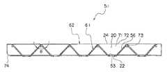
이하 본 발명을 도면에 도시하는 실시형태에 따라 설명한다. 도 1 및 도 2는 본 발명에 관한 라이트 박스의 일 실시형태를 도시하는 것이며, 도 1은 요부의 모 식적 분해사시도, 도 2는 요부의 모식적 단면도이다.EMBODIMENT OF THE INVENTION Hereinafter, this invention is demonstrated according to embodiment shown in drawing. 1 and 2 show an embodiment of a light box according to the present invention, FIG. 1 is a schematic exploded perspective view of a main portion, and FIG. 2 is a schematic cross-sectional view of the main portion.
도 1 및 도 2에 도시하는 바와 같이 본 실시형태의 라이트 박스(10)는 상부가 개구로 된 사각형의 상자체(12)를 가지고 있다. 이 상자체(12)의 내부의 바닥부에는 평면모양의 배선판(14)이 배설되어 있다. 그리고 배선판(14)의 윗면에는 복수의 램프 타입의 LED(점상광원,16)가 장착되어 있다. 이들 LED(16)는 배선판(14) 상에 매트릭스 모양으로 배열되어 있다. 또한, 배선판(14) 상에는 LED(16)로부터의 빛, 또는 광확산 표면판(26)이나 광확산 반사판(34)에서 반사된 빛을 반사하기 위한 광반사판(18)이 배치되어 있다.As shown in FIG. 1 and FIG. 2, the
광반사판(18)은 복수의 LED(16)의 각각의 주위를 둘러싸는 역다각추 형상, 본 실시형태에 있어서는 역사각추 형상으로 형성된 복수의 수납 요부(20)와, 이 수납 요부(20)의 바닥부의 중심에 형성된 LED(16)를 삽통이 가능한 삽통공(22)을 가지고 있다. 그리고 각 수납 요부(20)의 각각의 정상부(24)는 동일평면 내에 위치하도록 배설되어 있으며, 또한 각 수납 요부(20)의 정상부(24)가 인접한 수납 요부(20)의 정상부(24)와 접속되어 일체로 형성되어 있다. 또한, 수납 요부는 역사각추 형상에는 한정되지 않고, 그 외의 역다각추 형상, 예를 들면 역육각추 형상 등이라도 된다.The
보다 상세하게는 광반사판(18)은 도 2에 상세히 도시하는 바와 같이 인접한 LED(16)의 상호간의 중간부분이 가장 높이가 높은 정상부(24)로 되며, 삽통공(22)의 형성위치에 있어서 가장 높이가 낮은 삼각산 형상을 이루도록 형성되어 있다. 삽통공(22)에 LED(16)가 삽통되어 수납 요부(20)의 배선판(14)과는 반대쪽의 윗면 쪽에 LED(16)가 돌출되어 있다. 또한, 수납 요부(20)로서는 인접한 수납 요부(20)의 정상부(24)끼리가 직선모양으로 접속되어 있는 것이 표면조도의 불균일을 방지하는 데 긴요하다.In more detail, as shown in detail in FIG. 2, the
상기 광반사판(18)의 위쪽에는 투광성의 광확산 표면판(26)이 배설되어 있다. 이 광확산 표면판(26)은 광반사판(18)과 마주보도록 상자체(12)의 개구부에 배치되어 있다.On the upper side of the
또한, 도 2에 도시하는 바와 같이 수납 요부(20)의 정상부(24)는 LED(16)의 발광부(28)로부터 광확산 표면판(26)까지의 거리의 이등분점(30) 이하이며, LED(16)의 발광부(28) 이상의 부위에 위치하고 있다.2, the
본 실시형태의 라이트 박스(10)에서는 각 LED(16)간의 공간을 메우도록 또는 각 LED(16)가 역다각추 형상으로 만들어진 수납 요부(20)의 바닥부(20)에 뚫은 삽통공(22)으로부터 나타나도록 광반사판(18)이 배치되어 있다. 따라서 LED(16)는 각 수납 요부(20)의 바닥부(20)의 삽통공(22)으로부터 표면쪽으로 나타나도록 미리 배선판(14)에 배치배선되어 있다. 삽통공(22)으로부터 LED(16)가 나타나 있으므로 LED(16)로부터 발광된 빛은 광확산 표면판(26)으로 향한다.In the
광반사판(18)의 삽통공(22)과 LED(16)와의 사이에는 LED(16) 등으로부터 발생하는 열을 발산시키기 위해서나 배선판(14)과 광반사판(18)의 열팽창율의 차이로 인한 위치의 어긋남을 완화하기 위해서 등의 필요에 따라 1㎜ 이상의 거리의 틈을 두면 된다.Position between the
또한, 본 실시형태에서는 도 2에 도시하는 바와 같이 광반사판(18)과 광확산 표면판(26)과의 사이에 복수의 관통공을 가진 광확산 반사판(34)이 설계 컨셉 등의 필요에 따라 배설되도록 되어 있다.In addition, in this embodiment, as shown in FIG. 2, the light-
본 실시형태의 라이트 박스(10)에서는 광원으로서의 점상광원인 LED(16)로부터 발광된 지향성이 강한 빛은 광확산 표면판(26)에 달하면 전광선 투과율에 관련하여 일부가 투과하고, 나머지는 반사하여 내부로 되돌아간다. 내부로 되돌아간 빛은 광원간에 설치된 광반사판으로 90% 이상이 확산반사되며, 다시 광확산 표면판(26)에 도달한다. 이때 수납 요부(20)의 정상부(24)가 LED(16)의 발광부(28)로부터 광확산 표면판(26)까지의 거리의 이등분점 이하로 함으로써 수납 요부(20)의 정상부(24)가 너무 높으면 LED(16)의 빛이 광확산 표면판(26)에 닿는 것을 차단하는 부분이 너무 많아지며, 복수의 수납 요부(20)의 LED(16)로부터의 빛이 차단되지 않고 모인 부분이 너무 밝은 광불균일로 되는 것을 방지할 수 있도록 되어 있다.In the
또한, 광원으로부터 발광된 빛은 시야각이 작은 것이면 지향성이 강하므로 전혀 광반사판(18)에 반사되지 않고 직접 광확산 표면판(26) 방향으로 가며, 시야각이 큰 경우에도 대부분이 반사되지 않고 직접 광확산 표면판(26) 방향으로 간다. 이때 광확산 표면판(26)의 전광선 투과율이 높고 확산투과율이 낮은 경우에는 광원으로부터의 빛은 광확산 표면판(26)에서 그다지 확산하지 않고 광확산 표면판(26)을 통과하며, 광확산 표면판(26)에는 빛이 도달통과하여 밝은 곳과 빛이 도달하지 않고 어두운 곳이 생겨서 불균일이 생겨 버린다. 시야각이 큰 광원의 경우라도 중심은 휘도가 높고 단부(端部)는 휘도가 낮으므로 역시 불균일이 발생한다.In addition, since the light emitted from the light source is highly directional when the viewing angle is small, the light emitted from the light source is directed to the light
본 실시형태의 광반사판(18)은 광원으로부터 발생하여 광확산 표면판(26)에 도달한 빛은 50% 이상이 다시 내부측으로 반사되며, 광원간의 공간에 설치된 광반사판(18)에서 반사되어 되돌아간 빛의 90% 이상이 확산반사되어 다시 광확산 표면판(26)에 도달한다. 또한, 본 실시형태의 광반사판(18)은 광원이 배치되어 있지 않은 공간에서 광반사판(18)이 높고, 광원 근처에서 낮아 절구모양으로 되어 있다. 그러므로 광확산 표면판(26)에서 반사된 빛은 광반사판(18)이 높은 부분에서 효율적으로 반사하고, 도달하는 빛이 본래 적은 광원간의 공간상의 광확산 표면판(26)으로도 많이 도달하게 되어 광불균일이 적게 된다.The
일반적으로 라이트 박스(10)를 박형화하면 발광부(28)로부터 광확산 표면판(26)까지의 거리가 짧아지므로 광불균일이 문제가 되기 쉽다. 그러므로 본 발명에 있어서는 광반사판(18)의 정상부(24)와 광확산 표면판(26)과의 사이에 복수의 관통공을 가지며, 또한 양면이 반사하는 광확산 반사판(34)을 설치함으로써 한층 더 박형화가 가능해진다.In general, when the
상기 광확산 반사판(34)은 그 양면에 있어서의 가시광의 확산반사율이 모두 90% 이상인 것이 바람직하다. 광확산 반사판(34)의 양면의 확산반사율이 모두 90% 이상이면 광원의 빛의 난반사효과가 높아진다.It is preferable that all of the
또한, 상기 광확산 반사판(34)은 관통공을 여러 개 갖는 것이 바람직하다. 관통공의 형상은 특별히 한정되지 않으며, 각종 다각형, 별모양, 타원형 등으로 절절히 선택할 수 있으나, 일반적으로는 관통공의 형상이 원형이며, 그 직경이 0.3 내지 3㎜인 것이 바람직하다. 관통공의 형상을 원형으로 하면 그 성형이 용이해지지만, 그 직경이 0.3 ㎜ 미만이면 일반적인 천공(穿孔)방법을 사용할 수 없으며, 형성이 곤란해져서 생산성이 저하되며, 코스트상의 문제가 생긴다. 또한, 모든 관통공은 동일직경이라도 되며, 다른 직경의 것이 혼재해 있어도 된다.In addition, the
상기 광확산 반사판(34)의 개공율(開孔率)은 광확산 반사판(34)의 면적의 20 내지 40%, 바람직하게는 25 내지 35%이다. 단, 광원의 발광부 바로 위에는 관통공이 존재하지 않도록 광확산 반사판(34)에 관통공을 형성한 경우, 즉 광원의 직접광의 대부분을 막도록 관통공을 형성한 경우에는 개공율은 50 내지 90%인 것이 바람직하다.The porosity of the
광원으로서 LED(16)를 사용한 경우, 관 모양 광원과 달리 빛의 지향성이 강하므로 표면 조도(照度)에 불균일이 발생하기 쉽다. 특히 발광부(28)로부터 광확산 반사판(34)까지의 거리가 짧은 경우에는 불균일이 매우 발생하기 쉽다. 그러므로 본 발명에서는 전술한 광확산 반사판(34)을 사용함으로써 광원의 직접광이 광확산 표면판(26)에 도달하는 비율을 줄일 수 있다.In the case where the
즉 광원의 발광부(28)로부터 발광된 빛의 일부는 광확산 반사판(34)의 관통공으로부터 통과하여 광확산 표면판(26)의 뒷면에 도달하며, 나머지는 한번 광확산 반사판(34)에 닿아 반사되어 광원측으로 되돌아간다. 이 광확산 반사판(34)에서 반사되어 되돌아간 빛은 광반사판(18)에 의하여 반사되어 다시 광확산 반사판(34)측으로 향한다. 그리고 광확산 반사판(34)의 관통공을 통과하여 광확산 표면판(26)에 달한 빛은 광확산 표면판(26)의 전광선 투과율에 관련하여 일부가 표면에 투과하고, 나머지는 다시 광확산 반사판(34)측으로 되돌아간다. 이것을 반복함으로써 지향성이 강한 빛은 광확산 표면판(26)의 표면 전체에 널리 퍼져 광불균일을 실용상 문제가 없는 것으로 할 수 있다.That is, a part of the light emitted from the
따라서 광확산 반사판(34)을 형성하는 구성으로 한 경우는 광원으로부터 광확산 표면판(26)으로 향하는 빛을 광확산 반사판(34)에서 일단 광원측으로 되돌려서 확산반사시킬 수 있으며, 지향성이 강한 빛을 확산광으로 바꾸면서 다시 표면측으로 향하게 하는 수단을 2단계로 형성한 셈이 된다. 이에 따라 박형화를 보다 용이하게 도모할 수 있다.Therefore, in the case where the
본 발명에 있어서 점상광원의 종류, 형상 등은 특별히 한정되지 않으며, 포탄형 LED, 표면실장(實裝)형 LED 등으로부터 적절히 선택할 수 있다. 또한, 발광색으로서는 적색, 녹색, 청색, 황색, 백색 어느 것이라도 된다. 시야각도 특별히 한정되지 않으나, 50 내지 140°의 것이 바람직하다. 또한, 광원의 밝기는 사용전력량에 관련되므로 상황에 따라 적절히 선택할 수 있다. 그리고 또한 1개의 수납 요부(20)에 수납되는 점상광원의 수로서는 백색의 발광색을 띠는 1개의 점상광원을 배치하는 구성이나 적색, 청색, 녹색의 3가지 색의 발광색을 각각 띠는 3개의 점상광원을 배치하는 구성 등과 같이 단수나 복수 어느 것이라도 된다.In this invention, the kind, shape, etc. of a point light source are not specifically limited, It can select suitably from a shell type LED, a surface mount type LED, etc. The light emitting color may be any of red, green, blue, yellow, and white. Although the viewing angle is not specifically limited, either, 50-140 degrees is preferable. In addition, since the brightness of the light source is related to the amount of power used, it can be appropriately selected according to the situation. In addition, the number of point light sources to be accommodated in one
본 발명에 있어서 광반사판(18) 및 광확산 반사판(34)은 내부에 평균기포지름이 빛의 파장 이상이며 50㎛ 이하인 미세한 기포 또는 기공을 가진 열가소성 수지의 필름 또는 시트에 의하여 형성하는 것이 바람직하다.In the present invention, the
상기 열가소성 수지의 필름 또는 시트의 재료로서는 예를 들면 폴리에틸렌, 폴리프로필렌, 폴리스티렌, 폴리염화비닐, 폴리염화비페닐, 폴리에틸렌테레프탈레이트, 폴리비닐알코올 등의 범용수지, 폴리카보네이트, 폴리부틸렌테레프탈레이트, 폴리에틸렌나프탈레이트, 폴리아미드, 폴리아세탈, 폴리페닐렌에테르, 초고분자량 폴리에틸렌, 폴리술폰, 폴리에테르술폰, 폴리페닐렌설파이드, 폴리아릴레이트, 폴리아미드이미드, 폴리에테르이미드, 폴리에테르에테르케톤, 폴리이미드, 폴리테트라플루오로에틸렌, 액정 폴리머, 불소 수지 등의 엔지니어링 플라스틱, 또는 이들의 공중합체 또는 혼합물 등을 들 수 있다. 이들 중에서도 내열성, 내충격성 등이 양호하므로 폴리에스테르, 폴리페닐렌설파이드, 폴리프로필렌, 시클로폴리올레핀이 바람직하다. 또한, 상기 열가소성 수지 중에는 산화방지제, 자외선 방지제, 활제, 안료, 강화제 등을 적절히 첨가할 수 있다. 또한, 이들 첨가제를 함유한 도포층을 도포하여 형성해도 된다.As the material of the film or sheet of the thermoplastic resin, for example, general-purpose resins such as polyethylene, polypropylene, polystyrene, polyvinyl chloride, polyphenyl biphenyl, polyethylene terephthalate, polyvinyl alcohol, polycarbonate, polybutylene terephthalate, Polyethylene naphthalate, polyamide, polyacetal, polyphenylene ether, ultra high molecular weight polyethylene, polysulfone, polyether sulfone, polyphenylene sulfide, polyarylate, polyamideimide, polyetherimide, polyetheretherketone, polyimide And engineering plastics such as polytetrafluoroethylene, liquid crystal polymers, and fluororesins, or copolymers or mixtures thereof. Among these, polyester, polyphenylene sulfide, polypropylene, and cyclopolyolefin are preferable because of good heat resistance and impact resistance. In the thermoplastic resin, an antioxidant, a sunscreen, a lubricant, a pigment, a reinforcing agent, and the like can be appropriately added. Moreover, you may apply | coat and form the application layer containing these additives.
보다 구체적으로는 상기 열가소성 수지의 필름 또는 시트의 일례로서 열가소성 폴리에스테르의 압출 시트에 탄산가스를 고압 하에서 함침시킨 후 가열하여 발포시킨 시트이며, 내부의 기포지름이 50㎛ 이하인 폴리에스테르계 발포 시트(예를 들면 후루카와덴키고교 가부시키가이샤제 MCPET(등록상표))를 사용할 수 있다. 그 외에 동일하게 내부의 기포지름이 50㎛ 이하인 시클로폴리올레핀계 발포 시트를 사용할 수 있다.More specifically, as an example of the film or sheet of the thermoplastic resin, a sheet obtained by impregnating carbon dioxide gas in a thermoplastic polyester extruded sheet under high pressure and then heating and foaming, and having a polyester foam sheet having an internal bubble diameter of 50 μm or less ( For example, MCPET (registered trademark) manufactured by Furukawa Denki Kogyo Co., Ltd. may be used. In addition, a cyclopolyolefin foam sheet having an internal bubble diameter of 50 µm or less can be used.
또한, 광반사판(18) 및 광확산 반사판(34)을 형성하는 재료의 다른 바람직한 예로서 충전재를 함유하는 열가소성 수지의 필름 또는 시트에 있어서 충전재를 핵으로서 다수의 보이드가 형성되어 있는 필름 또는 시트를 들 수 있다. 이 경우 상기 필름 또는 시트에 있어서 충전재를 함유하는 미연신 필름 또는 시트는 충전재를 함유하는 미연신 필름 또는 시트를 성형하며, 이 미연신 필름 또는 시트를 연신함 으로써 충전재를 핵으로서 다수의 보이드를 형성한 다공성 연신 필름 또는 시트인 것이 바람직하다.Further, as another preferred example of the material for forming the
광반사판(18) 및 광확산 반사판(34)의 두께는 200 내지 2000㎛인 것이 바람직하다. 광반사판(18)의 두께가 200 내지 2000㎛의 범위 내이면 강성이 있으며, 광반사판 배면으로의 빛의 누설도 적다.It is preferable that the thickness of the
광반사판(18) 및 광확산 반사판(34)의 비중은 0.1 내지 0.7인 것이 바람직하다. 광반사판(18)의 비중이 0.7을 초과하면 다른 요건을 충족하여도 광반사판(18)의 투명화에 의하여 광반사판(18) 배면으로의 빛의 누설이 많아지므로 광손실이 커진다.It is preferable that the specific gravity of the
광반사판(18) 및 광확산 반사판(34)의 가시광의 반사율은 90% 이상인 것이 바람직하다. 광반사판(18) 및 광확산 반사판(34)의 가시광의 반사율이 90% 이상이면 광원의 빛의 난반사효과가 높아진다. 또한, 본 발명에 있어서의 가시광의 확산반사율은 빛의 입사속(入射束)에 대한 확산반사속(擴散反射束)의 비를 말하며, 자기(自記)분광광도계에 의하여 550㎚의 파장으로 측정하며, 황산바륨의 미분말을 굳힌 백판(白板)의 확산반사율을 100%로 하고, 그 상대값으로서 구한 값을 말한다. 자기분광광도계로서는 예를 들면 UV-3100PC(시마쓰제작소제 상품명)를 사용할 수 있다.It is preferable that the reflectance of the visible light of the
본 발명에 있어서 광확산 표면판(26)으로서는 전광선 투과율이 20 내지 50%의 범위이며, 반사율이 50 내지 80%의 범위의 것이 적절히 사용되며, 예를 들면 아크릴 수지판, 폴리카보네이트판, 유리천, 염화비닐 수지 시트 등이 사용된다. 전광 선 투과율이 20 내지 50%의 범위이면 광확산 표면판(26)의 밝기를 얻기 위하여 필요한 광원의 양이 과다하게 많아지지 않으며, 또한 광원의 지향성이 강한 빛을 과다하게 투과하여 버리는 일이 없다. 광원이 LED(16)인 경우에는 LED 광원의 휘도가 높을수록 시야각이 작을수록 광확산 표면판(26)의 전광선 투과율은 상기 범위 내에서 작게 하는 것이 바람직하다. 또한, 전광선 투과율이란 JIS K 7105-1981에 준하여 구한 값이다.In the present invention, as the light diffusing
이하 실시예에 의하여 본 발명을 구체적으로 설명한다. 또한, 본 발명은 이것에 의하여 한정되는 것은 아니다.Hereinafter, the present invention will be described in detail with reference to Examples. In addition, this invention is not limited by this.
실시예Example 1 One
도 1, 도 2에 도시한 라이트 박스(10)를 제작하였다. 단, 광확산 반사판(34)은 설치하지 않았다. 구체적으로는 앞면이 개구된 상자체(12)의 바닥부에 배선판(14)을 설치하고, 이 배선판(14)에 복수의 광원을 그 발광부(28)가 개구를 향하도록 하여 세로방향 및 가로방향 각각에 등간격(等間隔)으로 매트릭스 모양으로 설치하고, 이들 광원간의 공간을 메우도록 광반사판(18)을 설치하였다. 광반사판(18)은 역사각추 형상의 수납 요부(20)가 정상부(24)에서 가로세로 연속하여 이어진 형상이며, 상기 수납 요부(20)의 바닥부에는 삽통공(22)이 형성되어 이 삽통공(22)으로부터 광원이 나타나 있다. 또한, 상자체(12)의 개구부분에는 투광성의 광확산 표 면판(26)을 설치하였다. 상기 상자체(12)의 치수는 세로 323㎜, 가로 903㎜, 깊이 90㎜이며, 배선판(14)의 치수는 세로 300㎜, 가로 900이다. 또한, 본 예에서는 수납 요부(20)의 정상부(24)는 광원의 발광부(28)로부터 광확산 표면판(26)까지의 거리의 이등분점 이하이며, 점상광원의 발광부(28) 이상의 부위에 위치하고 있다.The
광원으로서는 백색이고 시야각 50°, 밝기 2500mcd의 LED(16)를 사용하였다. LED(16) 개개의 전류값은 DC 15V일 때 21㎃이다. LED(16)의 직경은 5㎜이다. 이들 LED(16)는 30㎜ 간격으로 배선판(14)에 등간격으로 배치하였다. LED(16)는 가로로 30열, 세로로 10행의 매트릭스 모양으로 합계 300개 사용하였다.As a light source, the
광반사판(18)에는 평균기포지름 10㎛, 두께 1000㎛, 비중 0.325, 가시광의 확산반사율 97%의 폴리에틸렌테레프탈레이트 발포체(후루카와덴키고교 가부시키가이샤제, 상품명 MCPET)를 사용하였다. 광반사판(18)의 수납 요부(20)는 역사각추 형상이며, 정상부(24)가 연속하여 이어져 있으며, 바닥부에는 LED(16)를 삽통시키기 위한 삽통공(22)이 열려 있다. 치수는 광반사판(18)의 수납 요부(20)의 상부가 세로 30㎜ × 가로 30㎜, 바닥부가 세로 10㎜ × 가로 10㎜, 깊이가 38㎜, 삽통공(22)의 직경이 7㎜이다. 광반사판(18)의 바깥 치수는 세로 300㎜, 가로 900㎜, 높이 39㎜, 삽통공(22)의 피치는 30㎜이다. LED(16)와 광반사판(18)의 삽통공(22)과의 사이에는 1㎜ 폭의 틈을 형성하였다.As the
광확산 표면판(26)에는 세로 323㎜, 가로 903㎜, 두께 2㎜의 유백색 아크릴 수지판(미쓰비시 레이온 가부시키가이샤제, 상품명 아크릴라이트, 색 번호 #430)을 사용하였다. 이 광확산 표면판(26)의 전광선 투과율은 40%, 반사율은 60%이다.As the light-
실시예Example 2 2
상자체(12)의 깊이를 35㎜로 하였다. 광원으로서 백색이고 시야각 110°, 밝기 740mcd의 표면실장형 LED(16)를 사용하였다. LED(16) 개개의 전류값은 DC 24V일 때 17㎃이다. LED(16)의 치수는 3×2×1.2㎜이다. LED(16)의 발광부(28)로부터 광확산 표면판(26)까지의 거리를 25㎜로 하였다. 광반사판(18)의 수납 요부(20)의 깊이를 10㎜, 바깥 치수를 세로 300㎜, 가로 900㎜, 높이 11㎜로 하였다. LED(16)와 광반사판(18)의 삽통공(22)과의 사이에는 1.7 내지 2.5㎜ 폭의 틈을 형성하였다. 광확산 표면판(26)에는 세로 323㎜, 가로 903㎜, 두께 3㎜의 유백색 아크릴 수지판(미쓰비시 레이온 가부시키가이샤제, 상품명 아크릴라이트, 색 번호 #430)을 사용하였다. 이 광확산 표면판(26)의 전광선 투과율은 30%, 반사율은 70%이다. 그 외의 구성에 대하여는 실시예 1과 동일한 라이트 박스(미도시)를 형성하였다.The depth of the
비교예Comparative example 1 One
광반사판의 수납 요부의 치수를 상부가 세로 30㎜ × 가로 30㎜, 바닥부가 세로 10㎜ × 가로 10㎜, 깊이가 65㎜, 삽통공의 직경이 7㎜, 광반사판의 바깥 치수를 세로 300㎜, 가로 900㎜, 높이 66㎜, 삽통공(22)의 피치 30㎜로 한 것 이외는 실시예 1과 동일한 라이트 박스(미도시)를 형성하였다. 본 비교예 1에서는 수납 요부의 정상부는 광원의 발광부로부터 광확산 표면판까지의 거리의 이등분점 이하이며, 점상광원의 발광부 이상의 부위에는 위치하고 있지 않으며, 수납 요부의 정상 부가 너무 높은 부위에 위치하여 있다.The dimensions of the recessed part of the light reflecting plate are 30 mm long x 30 mm wide, 10 mm long 10 mm wide, 10 mm wide, 65 mm deep, 7 mm in diameter for the insertion hole, and 300 mm long outside the light reflecting plate. The light box (not shown) similar to Example 1 was formed except having made width 900mm, height 66mm, and the pitch of the
비교예Comparative example 2 2
광반사판의 수납 요부의 깊이를 18㎜, 광반사판의 바깥 치수를 세로 300㎜, 가로 900㎜, 높이 19㎜로 한 것 이외는 실시예 1과 동일한 라이트 박스(미도시)를 형성하였다. 본 비교예 2에서는 수납 요부의 정상부는 광원의 발광부로부터 광확산 표면판까지의 거리의 이등분점 이하이며, 점상광원의 발광부 이상의 부위에는 위치하고 있지 않으며, 수납 요부의 정상부가 너무 높은 부위에 위치하고 있다.The light box (not shown) similar to Example 1 was formed except having made the depth of the accommodating recessed part of the
비교예Comparative example 3 3
광반사판을 사용하지 않는 것 이외는 실시예 1과 동일한 라이트 박스(미도시)를 형성하였다.A light box (not shown) similar to Example 1 was formed except not using a light reflection plate.
다음으로, 하기 방법에 의하여 실시예 1, 2의 라이트 박스(10) 및 비교예 1, 2, 3의 라이트 박스의 평가를 하였다. 이 평가에서는 실시예 1, 2의 라이트 박스(10) 및 비교예 1, 2, 3의 라이트 박스의 광원을 점등시키고, 광확산 표면판(26)에 직접 조도계의 수광부를 접촉시켜서 7군데의 조도를 측정하였다. 조도측정기로서는 요코가와 M & C사제의 일반 AA급 조도계(형명 51002)를 사용하였다. 광확산 표면판(26) 상의 측정위치 7군데는 LED(16) 위 및 인접한 4개의 LED(16)의 중심의 LED(16)가 없는 부분의 위를 측정하기 위하여 LED(16)의 매트릭스에 있어서의 하기 위치 A 내지 G로 하였다. 평가결과를 표 1에 나타낸다.Next, the
A: 3열-3행A: 3 columns-3 rows
B: 다음의 4점의 중심(15열-3행, 15열-4행, 16열-3행, 16열-4행)B: Center of the next four points (15 columns-3 rows, 15 columns-4 rows, 16 columns-3 rows, 16 columns-4 rows)
C: 28열-3행C: 28 columns-3 rows
D: 다음의 4점의 중심(15열-5행, 15열-6행, 16열-5행, 16열-6행)D: Center of 4 points (15 columns-5 rows, 15 columns-6 rows, 16 columns-5 rows, 16 columns-6 rows)
E: 3열-8행E: columns 3-8
F: 다음의 4점의 중심(15열-7행, 15열-8행, 16열-7행, 16열-8행)F: Center of four points (15 columns-7 rows, 15 columns-8 rows, 16 columns-7 rows, 16 columns-8 rows)
G: 28열-8행G: columns 28-8
Measuring area
표 1에 나타내는 바와 같이 실시예 1, 2에서는 전체 측정 부위에 있어서의 조도의 불규칙적인 분포가 작고, 표면조도에 실용상 문제가 되는 불균일이 없는 것이 판명되었다. 즉 빛의 지향성이 강한 광원을 사용하여도 표면조도에 불균일이 발생하지 않는 고품질의 것으로 되었다. 한편, 비교예 1, 2에서는 A, C, E, G는 밝고 LED가 없는 곳 위의 B, D, F는 어두워져서 표면조도의 불균일이 발생하였다. 또한, 비교예 3에서는 조도가 1/2 정도로 어두워져서 표면조도의 불균일도 발생하였다.As shown in Table 1, in Examples 1 and 2, the irregular distribution of roughness in all the measurement site | parts was small, and it turned out that there is no nonuniformity which becomes a problem practically in surface roughness. In other words, even when a light source with strong light directivity is used, it becomes a high quality product which does not generate unevenness in surface roughness. On the other hand, in Comparative Examples 1 and 2, A, C, E, and G were bright, and B, D, and F on the place where there was no LED became dark, resulting in uneven surface roughness. In addition, in Comparative Example 3, roughness was darkened to about 1/2, and unevenness of surface roughness also occurred.
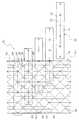
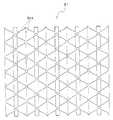
도 3에서부터 도 6은 본 발명에 관한 라이트 박스의 광반사판의 실시형태를 도시하는 것이며, 도 3은 모식적 평면도, 도 4는 도 3의 A-A선을 따른 확대단면도, 도 5는 도 3의 B-B선을 따른 확대단면도, 도 6은 도 3의 분해사시도이다. 또한, 전술한 실시형태의 광반사판(18)과 동일 내지 그에 상응하는 구성에 대하여는 도면 중에 동일한 부호를 달아 그 설명은 생략한다.3 to 6 show an embodiment of the light reflection plate of the light box according to the present invention, FIG. 3 is a schematic plan view, FIG. 4 is an enlarged cross-sectional view along the line AA of FIG. 3, FIG. 5 is BB of FIG. 3. 6 is an exploded perspective view of FIG. 3. In addition, about the structure similar to the
본 실시형태의 라이트 박스의 반광사판(이하 간단하게 광반사판이라 적는다(51))은 전술한 본 실시형태의 라이트 박스(10)에 사용할 수 있는 것을 예시하고 있다.The semi-reflective plate (hereinafter simply referred to as light reflective plate 51) of the light box of this embodiment exemplifies what can be used for the
도 3에 도시하는 바와 같이 본 실시형태의 반광사판(51)은 서로 직교하는 도 3의 상하방향으로 도시하는 세로방향으로 5열, 및 도 3의 좌우방향으로 도시하는 가로방향으로 4행의 매트릭스 모양으로 배열된 총계 20군데의 수납 요부(20)를 가지고 있다.As shown in FIG. 3, the semi-light-
도 3에서부터 도 5에 도시하는 바와 같이 상기 각 수납 요부(20)는 역사각추 형상, 상세하게는 바닥부가 정사각형을 이루도록 역방향의 머리를 잘라낸 사각추 형상으로 형성되어 있다. 즉 각 수납 요부(20)는 평면 정사각형으로 형성된 바닥부(53)와, 이 바닥부(53)의 끝 가장자리로부터 비스듬하게 위쪽을 향하여 뻗은 도립대(倒立臺) 형상의 4개의 경사면(54)을 가지고 있다.As shown in FIG. 3 to FIG. 5, each of the storage recesses 20 is formed in an inverted pyramidal shape, in detail, a square weight in which the head in the reverse direction is cut out to form a square. That is, each
상기 수납 요부(20)의 바닥부(53)의 중심에는 평면 원형의 삽통공(22)이 형성되어 있으며, 이 삽통공(22)에는 전술한 LED(도 1의 부호 16)가 삽통이 자유롭도록 되어 있다. 또한, 삽통공(22)의 형상으로서는 LED를 삽통할 수 있는 형상이면 되며, 타원형, 다각형 등의 각종 형상으로부터 선택할 수 있다.A flat
상기 각 수납 요부(20)의 각각의 정상부(24)는 동일 평면내에 위치하도록 배설되어 있으며, 또한 각 수납 요부(20)의 정상부(24)가 인접한 수납 요부(20)의 정상부(24)와 접속되어 있다.Each
또한, 본 실시형태에 있어서는 세로방향으로 배열되어 있는 수납 요부(20)의 양끝(위쪽 끝 및 아래쪽 끝)에 모조 수납 요부(52)가 형성되어 있다. 이들 모조 수납 요부(52)는 인접한 수납 요부(20)에 접속하는 3개의 경사면(55)과 바닥부(53)를 가지고 있다.In addition, in this embodiment, the dummy accommodating recessed
도 3에서부터 도 6에 도시하는 바와 같이 본 실시형태의 광반사판(51)은 제1부재(61)와, 본 실시형태에 있어서는 5개의 제2부재(62)에 의하여 형성되어 있다.As shown in FIG. 3 to FIG. 6, the
도 6에 도시하는 바와 같이 제1부재(61)는 각 수납 요부(20)의 서로 마주보는 두 면, 본 실시형태에 있어서는 세로방향으로 배열된 각 수납 요부(20, 모조 수납 요부(52)를 포함한다)의 가로방향으로 마주보는 두 개의 경사면(54)을 형성하는 세로방향으로 긴(세로방향으로 배열된 4개의 수납 요부(20)와 세로방향의 양끝에 배설된 2개의 모조 수납 요부(52)를 형성할 수 있는 길이) 산부(56)를 가지고 있으며, 이 산부(56)에는 6개의 산 모양의 개구(63)가 형성되어 있다. 이들 개구(63)는 수납 요부(20)의 바닥부(53)의 모서리로부터 세로방향으로 인접하여 위치한 수납 요부(20)의 바닥부(53)의 마주보는 모서리를 향하여 직선모양으로 형성된 밑변(64)과, 이 밑변(64)의 양끝으로부터 세로방향으로 인접한 수납 요부(20)의 정상부(24)의 모서리를 향하여 직선모양으로 형성된 2개의 빗변(65)에 의하여 거의 산 모양, 본 실시형태에 있어서는 가로방향 대(臺) 형상으로 형성되어 있다.As shown in FIG. 6, the
따라서 세로방향으로 배열된 바닥부(53)를 연결하는 가상선을 대칭선으로 하여 가로방향으로 마주보는 2개의 개구(63) 사이에는 세로방향으로 인접하여 위치한 2개의 수납 요부(20, 세로방향의 양끝에 있어서는 수납 요부(20)와 모조 수납 요부(52))의 바닥부(53)를 접속하는 평면의 세로가 긴 직사각형 모양으로 형성된 접속받이부(69)가 형성되어 있다.Accordingly, two storage recesses 20 (vertical) located adjacent to each other in the vertical direction are disposed between two
또한, 개구(63)의 형상으로서는 거의 역V자 모양의 슬릿이라도 된다. 물론 개구(63)로서는 제2부재(62)를 삽입할 수 있는 것이라야 한다. 또한, 제1부재(61)는 제2부재(62)를 개구(63)에 삽입함으로써 수납 요부(20)로부터의 빛 누출이 없도록 개구(63)를 막을 수 있는 것이라야 한다.In addition, the shape of the
도 4에서부터 도 6에 도시하는 바와 같이 상기 제2부재(62)는 개구(63)를 직선모양으로 관통, 본 실시형태에 있어서는 가로방향으로 배열되어 있는 각 개구(63)를 가로방향으로 직선모양으로 관통하도록 삽입되는 것이며, 제1부재(61)의 가로방향의 길이보다 약간 길게 형성된 평판을 거의 역V자 모양으로 절곡한 산 모양으로 형성되어 있다. 또한, 제2부재(62)의 2개의 경사면(71)은 제1부재(61)의 개구(63)에 삽입된 상태이며, 개구(63)를 아래쪽으로부터 막고 개구(63)로부터 노출되어 있는 부분이 세로방향으로 인접한 2개의 수납 요부(20, 상하방향의 양끝에 있어서는 수납 요부(20)와 모조 수납 요부(52))가 인접하는 경사면(54)을 형성할 수 있도록 되어 있다.As shown in Figs. 4 to 6, the
상기 제2부재(62)의 정상부(72)는 제1부재(61)의 개구(63)에 삽입된 상태이며, 세로방향으로 인접한 2개의 수납 요부(20)의 각각의 정상부(24)를 형성할 수 있도록 되어 있다. 또한, 제2부재(62)의 정상부(72)에는 제1부재(61)에 형성되어 있는 정상부(24)가 위쪽으로부터 감합되는 6개의 감합용 개구(73)가 형성되어 있으며, 제1부재(61)에 제2부재(62)를 삽입한 상태에서 각 수납 요부(20)의 4개의 정상부(24)가 동일 평면에 위치하도록 형성되어 있다.The
또한, 6개의 감합용 개구(73) 중 배열방향의 양끝의 2개의 감합용 개구(73)에는 각각 1개의 수납 요부(20)의 정상부(24)가 감합되도록 되어 있다. 또한, 6개의 감합용 개구(73) 중 배열방향의 양끝보다 안쪽의 4개의 감합용 개구(73)에는 가로방향에 인접하여 위치한 2개의 수납 요부(20)의 각각의 정상부(24)가 감합되도록 되어 있다.Moreover, the
상기 제1부재(61)에 제2부재(62)를 삽입한 상태에서는 제1부재(61)의 접속받이부(69)가 제2부재(62)의 바닥부(53)를 아래쪽으로부터 지지할 수 있도록 형성되어 있다.In a state where the
또한, 제2부재(62)의 바닥부(53)의 적어도 제1부재(61)에 대한 삽입측에는 삽입 가이드가 되는 모떼기(74)를 형성하는 것이 바람직하다.In addition, it is preferable to form a
그 외의 광반사판(51)의 구성에 대해서는 전술한 제1실시형태의 라이트 박스(10)의 광반사판(18)과 동일하게 구성되어 있으므로 그 상세한 설명은 생략한다.Since the structure of the other
이와 같은 구성으로 이루어진 광반사판(51)에 의하면 전술한 실시형태의 라이트 박스(10)의 광반사판(18)과 동일하게 광반사판(51)의 수납 요부(20)가 역다각추 형상으로 형성되어 있으므로 수납 요부(20)에서 반사된 빛은 수납 요부(20)의 벽면에서 효율적으로 반사하며, 도달하는 빛의 본래 적은 광원간의 공간상으로도 많이 도달하므로 빛의 지향성이 강한 광원을 사용한 경우라도 라이트 박스(10)의 박형화를 도모하면서 표면조도에 불균일이 발생하는 것을 방지할 수 있는 등의 매우 뛰어난 효과를 가져올 수 있는 동시에 수납 요부(20)를 용이하게 형성할 수 있다.According to the
다음으로, 본 실시형태의 광반사판(51)의 제조방법에 대하여 설명한다.Next, the manufacturing method of the
본 실시형태의 광반사판(51)의 제조방법은 수납 요부(20)의 서로 마주보는 2면을 형성하는 산부(56)를 가지며, 이 산부(56)에 산 모양의 개구(63)를 가진 제1부재(61)를 형성하며, 개구(63)를 직선모양으로 관통하도록 삽입되는 산 모양의 제2부재(62)를 형성하며, 제1부재(61)의 개구(63)에 제2부재(62)를 삽입함으로써 수납 요부(20)를 형성하도록 되어 있다.The manufacturing method of the
상기 제1부재(61)는 예를 들면 필름 또는 시트를 블랭킹한 후에 절곡하여 형성되어 있다. 이 필름 또는 시트를 블랭킹한 후의 제1부재용 중간품(81)의 일례를 도 7에 도시한다. 또한, 시트를 블랭킹한 후의 제1부재용 중간품(81)에는 절곡을 용이하게 하기 위하여 접은 선 부분에 시트를 두께방향으로 압축한 직선모양의 접은 선(81a)을 형성하는 것이 바람직하다. 이 접은 선(81a)을 도 7에 파선으로 나타낸다.The
상기 제2부재(62)는 예를 들면 필름 또는 시트를 블랭킹한 후에 절곡하여 형성되어 있다. 이 필름 또는 시트를 블랭킹한 후의 제2부재용 중간품(82)의 일례를 도 8에 도시한다. 또한, 시트를 블랭킹한 후의 제2부재용 중간품(82)에는 절곡을 용이하게 하기 위하여 접은 선 부분에 시트를 두께방향으로 압축한 직선모양의 접은 선(82a)을 형성하는 것이 바람직하다. 이 접은 선(82a)을 도 8에 파선으로 나타낸다.The
이어서 도 6에 도시하는 바와 같이 제1부재(61)의 개구(63)에 제2부재(62)를 모떼기(74)의 형성 끝쪽으로부터 삽입함으로써 도 3에 도시하는 광반사판(51)의 제조가 완료된다. 또한, 제1부재(61)의 개구(63)에 제2부재(62)를 삽입하기 전에 제1부재(61)의 산부(56)의 꼭지각의 각도 θ(도 5)를 미리 설정되어 있는 각도보다 작게 하는 것이 제1부재(61)의 개구(63)의 도 6의 좌우방향으로 나타내는 높이방향을 따른 수직방향의 거리가 길어지며, 제2부재(62)를 삽입하기 쉽게 할 수 있다는 의미에서 바람직하다. 또한, 제1부재(61)의 산부(56)의 꼭지각의 각도(θ)를 미리 설정되어 있는 각도보다 작게 하는 것은 제1부재(61)의 도 6의 좌우방향의 거리를 짧게 하도록 도 6의 좌우방향의 양측으로부터 안쪽을 향하여 힘을 부여하면 된다. 또한, 제1부재(61)의 개구(63)에 제2부재(62)를 삽입한 후에 제1부재(61)의 산부(56)의 꼭지각의 각도를 원래의 각도로 되돌리는 것이 긴요하다.Subsequently, as shown in FIG. 6, the
즉 본 실시형태의 광반사판(51)의 제조방법은 프레스 가공에 의하여 필름 또는 시트에 블랭킹 및 벤딩을 이 순서에 따라 실시하고 제1부재(61)와 제2부재(62)의 각각을 개별적으로 형성하는 가공공정과, 제1부재(61)의 가로방향 또는 세로방향으로 배열되어 있는 개구(63)에 제2부재(62)를 삽입하여 제1부재(61)의 개구(63)를 제2부재(62)에 의하여 막아 복수의 수납 요부(20)를 형성하도록 조립하는 조립공정을 포함하도록 구성되어 있다. 또한, 가공공정에 있어서의 블랭킹 및 벤딩을 차례로 이송하는 형식에 따라 이 순서대로 실시하는 것이 바람직하다. 또한, 접은 선(81a, 82a)의 형성을 하는 경우에는 블랭킹, 접은 선의 81a, 82a의 형성을 위한 압축가공 및 벤딩을 차례로 이송하는 형식에 따라 이 순서대로 실시하는 것이 바람직하다.That is, in the manufacturing method of the
또한, 도 6은 본 발명에 관한 라이트 박스의 광반사판의 제조방법의 실시형태에 있어서의 제1부재(61)에 제2부재(62)를 삽입하여 조립하는 조립상태를 설명하는 설명도이다.6 is explanatory drawing explaining the assembly state which inserts and assembles the
이와 같은 구성으로 이루어진 본 실시형태의 광반사판(51)의 제조방법에 의하면 수납 요부(20)의 서로 마주보는 두 면을 형성하는 산부(56)를 가지며, 이 산부(56)에 산 모양의 개구(63)를 가진 제1부재(61)를 형성하며, 개구(63)를 직선모양으로 관통하도록 삽입되는 산 모양의 제2부재(62)를 형성하며, 제1부재(61)의 개구(63)에 제2부재(62)를 삽입함으로써 수납 요부(20)를 형성하므로 역사각추 형상으로 형성된 복수의 수납 요부(20)를 용이하게 형성할 수 있다.According to the manufacturing method of the
즉 본 실시형태의 광반사판(51)을 확실하고 또한 용이하게 얻을 수 있는 등의 뛰어난 효과를 가져온다.That is, it brings about the outstanding effect, such as being able to acquire the
또한, 본 실시형태의 광반사판(51)의 제조방법에 의하면 제1부재(61)및 제2부재(62)의 각각을 필름 또는 시트를 블랭킹한 후에 절곡하여 형성하므로 본 실시형태의 광반사판(51)을 보다 용이하게 얻을 수 있는 등의 뛰어난 효과를 가져온다.In addition, according to the manufacturing method of the
또한, 본 발명은 전술한 각 실시형태에 한정되는 것이 아니라 필요에 따라 다양한 변경이 가능하다.In addition, this invention is not limited to each embodiment mentioned above, A various change is possible as needed.
Claims (13)
Translated fromKoreanApplications Claiming Priority (5)
| Application Number | Priority Date | Filing Date | Title |
|---|---|---|---|
| JP2005282142 | 2005-09-28 | ||
| JPJP-P-2005-00282142 | 2005-09-28 | ||
| JPJP-P-2005-00375362 | 2005-12-27 | ||
| JP2005375362 | 2005-12-27 | ||
| PCT/JP2006/309788WO2007037035A1 (en) | 2005-09-28 | 2006-05-17 | Light box, light reflector for the same, and method for producing light reflector |
Publications (2)
| Publication Number | Publication Date |
|---|---|
| KR20080063274A KR20080063274A (en) | 2008-07-03 |
| KR101285490B1true KR101285490B1 (en) | 2013-07-12 |
Family
ID=37899471
Family Applications (1)
| Application Number | Title | Priority Date | Filing Date |
|---|---|---|---|
| KR1020087006143AExpired - Fee RelatedKR101285490B1 (en) | 2005-09-28 | 2006-05-17 | Light box, light reflector for the same, and method for producing light reflector |
Country Status (4)
| Country | Link |
|---|---|
| JP (1) | JP5100389B2 (en) |
| KR (1) | KR101285490B1 (en) |
| CN (1) | CN101273231B (en) |
| WO (1) | WO2007037035A1 (en) |
Families Citing this family (46)
| Publication number | Priority date | Publication date | Assignee | Title |
|---|---|---|---|---|
| US7828456B2 (en) | 2007-10-17 | 2010-11-09 | Lsi Industries, Inc. | Roadway luminaire and methods of use |
| KR20130014605A (en) | 2008-01-08 | 2013-02-07 | 돌비 레버러토리즈 라이쎈싱 코오포레이션 | Display device with reduced parallax |
| TWI364557B (en) | 2008-05-02 | 2012-05-21 | Chimei Innolux Corp | Light source and backlight module and liquid crystal display device using same |
| JP2009289687A (en)* | 2008-05-30 | 2009-12-10 | Furukawa Electric Co Ltd:The | Light reflecting plate and manufacturing method therefor |
| JP4802215B2 (en)* | 2008-06-10 | 2011-10-26 | 古河電気工業株式会社 | light box |
| KR101029375B1 (en)* | 2008-07-22 | 2011-04-13 | 주식회사 라이트론 | LED lighting |
| JP5309826B2 (en)* | 2008-09-18 | 2013-10-09 | 凸版印刷株式会社 | Optical sheet, backlight unit and display device |
| JP4528911B2 (en)* | 2008-10-07 | 2010-08-25 | 株式会社オプトデザイン | LIGHT SOURCE DEVICE AND LIGHTING DEVICE USING THE LIGHT SOURCE DEVICE |
| JP5333910B2 (en)* | 2008-12-26 | 2013-11-06 | 東芝ライテック株式会社 | Luminescent panel and lighting fixture |
| JP4801178B2 (en)* | 2009-02-13 | 2011-10-26 | 株式会社コスモテック | Light reflector and planar light source device |
| JP2010198814A (en)* | 2009-02-24 | 2010-09-09 | Mitsubishi Plastics Inc | Backlight unit, member of backlight unit, and liquid crystal display device |
| CN101832508A (en)* | 2009-03-09 | 2010-09-15 | 锐光照明系统(上海)有限公司 | Light reflecting device of transmission-type backlight LED light box and light box |
| KR100933020B1 (en)* | 2009-05-15 | 2009-12-23 | 주식회사 선에너지엘이디 | LED street light with improved heat and light |
| KR100933022B1 (en)* | 2009-05-15 | 2009-12-23 | 주식회사 선에너지엘이디 | LED street light with improved illumination |
| KR100926040B1 (en)* | 2009-05-19 | 2009-11-11 | 주식회사 케이디파워 | LED lighting |
| CN102428317B (en)* | 2009-05-22 | 2015-07-22 | 夏普株式会社 | Light source device and display device |
| KR200447813Y1 (en)* | 2009-06-16 | 2010-02-24 | 이정태 | Bubble mood surface lighting device equipped with bubble mood surface light-emitting body and bubble mood surface light-emitting body |
| KR200448165Y1 (en)* | 2009-07-16 | 2010-03-24 | 조경숙 | LED lighting |
| US8794787B2 (en) | 2009-11-10 | 2014-08-05 | Lsi Industries, Inc. | Modular light reflectors and assemblies for luminaire |
| KR101121023B1 (en)* | 2010-01-12 | 2012-03-20 | 우리조명 주식회사 | Led lighting apparatus |
| JP5380335B2 (en)* | 2010-03-04 | 2014-01-08 | 積水化成品工業株式会社 | Reflector, lighting device, and display device |
| CN101852388A (en)* | 2010-06-23 | 2010-10-06 | 深圳市九洲光电科技有限公司 | Wide-angle light-distribution lens for LEDs and application thereof |
| WO2011162258A1 (en)* | 2010-06-25 | 2011-12-29 | 株式会社オプトデザイン | Illumination device |
| CN101915374A (en)* | 2010-07-09 | 2010-12-15 | 王默文 | LED lamphouse light source system |
| JP5667804B2 (en)* | 2010-07-13 | 2015-02-12 | 積水化成品工業株式会社 | Light reflector and manufacturing method thereof |
| JP5635326B2 (en)* | 2010-07-29 | 2014-12-03 | パナソニック株式会社 | lighting equipment |
| JP5635325B2 (en)* | 2010-07-29 | 2014-12-03 | パナソニック株式会社 | lighting equipment |
| US20130128128A1 (en)* | 2010-07-30 | 2013-05-23 | Sharp Kabushiki Kaisha | Lighting device, display device and television device |
| WO2012023459A1 (en)* | 2010-08-20 | 2012-02-23 | シャープ株式会社 | Illuminating device, display device and television receiver |
| CN102109109B (en)* | 2010-11-11 | 2016-01-13 | 深圳辰泽半导体照明有限公司 | LED shadowless lamp |
| KR101113589B1 (en)* | 2011-04-06 | 2012-03-05 | (주) 파루 | Antiglare plate for lighting device and menufacture method thereof |
| TWI453927B (en) | 2011-06-29 | 2014-09-21 | Ind Tech Res Inst | Multiple reflection structure and optoelectronic components |
| CN102494248A (en)* | 2011-11-27 | 2012-06-13 | 东莞市博伦光电科技有限公司 | Portable lamp |
| CN103244861B (en)* | 2012-02-03 | 2015-11-25 | 北京莱易龙光电科技有限公司 | A kind of light source module for LED case |
| JP6186904B2 (en)* | 2013-06-05 | 2017-08-30 | 日亜化学工業株式会社 | Light emitting device |
| US9541255B2 (en) | 2014-05-28 | 2017-01-10 | Lsi Industries, Inc. | Luminaires and reflector modules |
| JP6414485B2 (en) | 2015-02-27 | 2018-10-31 | 日亜化学工業株式会社 | Light emitting device |
| CN118408170A (en)* | 2015-05-15 | 2024-07-30 | 索尼公司 | Light emitting device, display device, and lighting device |
| CN106855664A (en)* | 2015-12-09 | 2017-06-16 | 天津三星电子有限公司 | A kind of LCDs |
| KR101781162B1 (en) | 2016-01-14 | 2017-09-22 | 이엔이엘이디 주식회사 | LED lighting apparatus |
| CN106377075A (en)* | 2016-11-15 | 2017-02-08 | 成都信息工程大学 | Isotropous reading illumination method and system |
| CN108287433A (en)* | 2017-12-28 | 2018-07-17 | 重庆市中光电显示技术有限公司 | Backlight module and reflector plate applied to backlight module |
| JP2018091624A (en)* | 2018-03-16 | 2018-06-14 | 東芝ライフスタイル株式会社 | refrigerator |
| CN110680937B (en)* | 2019-11-08 | 2023-05-02 | 中国科学院半导体研究所 | Ultraviolet LED light homogenizing device and application thereof |
| CN111105731A (en)* | 2019-12-20 | 2020-05-05 | 福建升腾资讯有限公司 | Even light structure, backlight and pilot lamp |
| JP2021162720A (en)* | 2020-03-31 | 2021-10-11 | 日本カーバイド工業株式会社 | Light-diffusing film and method for manufacturing light-diffusing film |
Citations (4)
| Publication number | Priority date | Publication date | Assignee | Title |
|---|---|---|---|---|
| JP3195294B2 (en)* | 1998-08-27 | 2001-08-06 | スタンレー電気株式会社 | Vehicle lighting |
| JP2003005677A (en) | 2001-06-20 | 2003-01-08 | Fujitsu General Ltd | LED display unit |
| JP2004006317A (en) | 2002-04-17 | 2004-01-08 | Box:Kk | Surface light-emitting device |
| JP2005235581A (en) | 2004-02-19 | 2005-09-02 | Nitto Denko Corp | Direct type backlight |
Family Cites Families (8)
| Publication number | Priority date | Publication date | Assignee | Title |
|---|---|---|---|---|
| JPH0510369Y2 (en)* | 1989-09-05 | 1993-03-15 | ||
| JPH0420989A (en)* | 1990-05-16 | 1992-01-24 | Hitachi Ltd | Panel light source device |
| EP0778477B1 (en)* | 1995-06-23 | 2002-10-02 | The Furukawa Electric Co., Ltd. | Light reflection plate |
| JPH10233112A (en)* | 1997-02-18 | 1998-09-02 | Tootasu Japan:Kk | Surface light source device and its manufacture |
| JP2003022701A (en)* | 2001-07-09 | 2003-01-24 | Furukawa Electric Co Ltd:The | light box |
| CN1175200C (en)* | 2001-12-18 | 2004-11-10 | 财团法人工业技术研究院 | LED lighting source device |
| JP4504662B2 (en)* | 2003-04-09 | 2010-07-14 | シチズン電子株式会社 | LED lamp |
| JP2005183531A (en)* | 2003-12-17 | 2005-07-07 | Sharp Corp | Semiconductor light emitting device |
- 2006
- 2006-05-17KRKR1020087006143Apatent/KR101285490B1/ennot_activeExpired - Fee Related
- 2006-05-17CNCN200680035689.5Apatent/CN101273231B/ennot_activeExpired - Fee Related
- 2006-05-17WOPCT/JP2006/309788patent/WO2007037035A1/enactiveApplication Filing
- 2006-05-17JPJP2007537528Apatent/JP5100389B2/ennot_activeExpired - Fee Related
Patent Citations (4)
| Publication number | Priority date | Publication date | Assignee | Title |
|---|---|---|---|---|
| JP3195294B2 (en)* | 1998-08-27 | 2001-08-06 | スタンレー電気株式会社 | Vehicle lighting |
| JP2003005677A (en) | 2001-06-20 | 2003-01-08 | Fujitsu General Ltd | LED display unit |
| JP2004006317A (en) | 2002-04-17 | 2004-01-08 | Box:Kk | Surface light-emitting device |
| JP2005235581A (en) | 2004-02-19 | 2005-09-02 | Nitto Denko Corp | Direct type backlight |
Also Published As
| Publication number | Publication date |
|---|---|
| WO2007037035A1 (en) | 2007-04-05 |
| JP5100389B2 (en) | 2012-12-19 |
| KR20080063274A (en) | 2008-07-03 |
| HK1125159A1 (en) | 2009-07-31 |
| CN101273231A (en) | 2008-09-24 |
| JPWO2007037035A1 (en) | 2009-04-02 |
| CN101273231B (en) | 2010-05-19 |
Similar Documents
| Publication | Publication Date | Title |
|---|---|---|
| KR101285490B1 (en) | Light box, light reflector for the same, and method for producing light reflector | |
| EP2138753A1 (en) | Light box | |
| US8061876B2 (en) | Illumination device | |
| JP5619406B2 (en) | Illumination body | |
| KR100755010B1 (en) | Lighting equipment | |
| TWI513942B (en) | A light source device, a lighting device and a display device | |
| CN101641547A (en) | Light box | |
| US20150268407A1 (en) | Lighting assembly | |
| EP1892563B1 (en) | Surface light source device, backlight unit and liquid crystal display having the same | |
| JP4802215B2 (en) | light box | |
| KR20120041765A (en) | Optical assembly | |
| US20150309241A1 (en) | Light guide and lighting assembly with array of rotated micro-optical elements | |
| US20100020568A1 (en) | Planar lighting device | |
| WO2007027434A1 (en) | Direct-lit backlight having light sources with bifunctional diverters | |
| US20120155083A1 (en) | Light source device, illumination device, and display device | |
| CN101038073A (en) | LED luminous source lamp box | |
| JP4316556B2 (en) | LED light source light box | |
| KR101949667B1 (en) | Illumination device | |
| JP2006202729A (en) | LED light source light box | |
| JP5574642B2 (en) | Illumination body | |
| KR20080063754A (en) | Surface light source device | |
| JP2003215346A (en) | Light guide plat | |
| HK1125159B (en) | Light box, light reflector for the same, and method for producing light reflector | |
| CN112285821B (en) | Lamp fitting | |
| KR101670365B1 (en) | Light-emitting element array, Backlight apparatus, and Illumination apparatus |
Legal Events
| Date | Code | Title | Description |
|---|---|---|---|
| PA0105 | International application | St.27 status event code:A-0-1-A10-A15-nap-PA0105 | |
| P11-X000 | Amendment of application requested | St.27 status event code:A-2-2-P10-P11-nap-X000 | |
| P13-X000 | Application amended | St.27 status event code:A-2-2-P10-P13-nap-X000 | |
| PG1501 | Laying open of application | St.27 status event code:A-1-1-Q10-Q12-nap-PG1501 | |
| PN2301 | Change of applicant | St.27 status event code:A-3-3-R10-R13-asn-PN2301 St.27 status event code:A-3-3-R10-R11-asn-PN2301 | |
| R17-X000 | Change to representative recorded | St.27 status event code:A-3-3-R10-R17-oth-X000 | |
| A201 | Request for examination | ||
| PA0201 | Request for examination | St.27 status event code:A-1-2-D10-D11-exm-PA0201 | |
| E902 | Notification of reason for refusal | ||
| PE0902 | Notice of grounds for rejection | St.27 status event code:A-1-2-D10-D21-exm-PE0902 | |
| E13-X000 | Pre-grant limitation requested | St.27 status event code:A-2-3-E10-E13-lim-X000 | |
| P11-X000 | Amendment of application requested | St.27 status event code:A-2-2-P10-P11-nap-X000 | |
| P13-X000 | Application amended | St.27 status event code:A-2-2-P10-P13-nap-X000 | |
| E701 | Decision to grant or registration of patent right | ||
| PE0701 | Decision of registration | St.27 status event code:A-1-2-D10-D22-exm-PE0701 | |
| GRNT | Written decision to grant | ||
| PR0701 | Registration of establishment | St.27 status event code:A-2-4-F10-F11-exm-PR0701 | |
| PR1002 | Payment of registration fee | St.27 status event code:A-2-2-U10-U12-oth-PR1002 Fee payment year number:1 | |
| PG1601 | Publication of registration | St.27 status event code:A-4-4-Q10-Q13-nap-PG1601 | |
| LAPS | Lapse due to unpaid annual fee | ||
| PC1903 | Unpaid annual fee | St.27 status event code:A-4-4-U10-U13-oth-PC1903 Not in force date:20160706 Payment event data comment text:Termination Category : DEFAULT_OF_REGISTRATION_FEE | |
| PC1903 | Unpaid annual fee | St.27 status event code:N-4-6-H10-H13-oth-PC1903 Ip right cessation event data comment text:Termination Category : DEFAULT_OF_REGISTRATION_FEE Not in force date:20160706 | |
| P22-X000 | Classification modified | St.27 status event code:A-4-4-P10-P22-nap-X000 | |
| R18-X000 | Changes to party contact information recorded | St.27 status event code:A-5-5-R10-R18-oth-X000 |