KR101283295B1 - Projection system using transparent foil - Google Patents
Projection system using transparent foilDownload PDFInfo
- Publication number
- KR101283295B1 KR101283295B1KR1020110064233AKR20110064233AKR101283295B1KR 101283295 B1KR101283295 B1KR 101283295B1KR 1020110064233 AKR1020110064233 AKR 1020110064233AKR 20110064233 AKR20110064233 AKR 20110064233AKR 101283295 B1KR101283295 B1KR 101283295B1
- Authority
- KR
- South Korea
- Prior art keywords
- transparent foil
- image
- projection system
- projector
- mirror
- Prior art date
- Legal status (The legal status is an assumption and is not a legal conclusion. Google has not performed a legal analysis and makes no representation as to the accuracy of the status listed.)
- Active
Links
- 239000011888foilSubstances0.000titleclaimsabstractdescription83
- 238000004804windingMethods0.000claimsdescription21
- 238000000034methodMethods0.000claimsdescription2
- 238000009434installationMethods0.000abstractdescription9
- 230000001737promoting effectEffects0.000abstractdescription2
- 238000010586diagramMethods0.000description9
- 235000002566CapsicumNutrition0.000description1
- 239000006002PepperSubstances0.000description1
- 235000016761Piper aduncumNutrition0.000description1
- 235000017804Piper guineenseNutrition0.000description1
- 244000203593Piper nigrumSpecies0.000description1
- 235000008184Piper nigrumNutrition0.000description1
- NIXOWILDQLNWCW-UHFFFAOYSA-Nacrylic acid groupChemical groupC(C=C)(=O)ONIXOWILDQLNWCW-UHFFFAOYSA-N0.000description1
- 230000000694effectsEffects0.000description1
- 238000005516engineering processMethods0.000description1
- 239000000463materialSubstances0.000description1
- NJPPVKZQTLUDBO-UHFFFAOYSA-NnovaluronChemical compoundC1=C(Cl)C(OC(F)(F)C(OC(F)(F)F)F)=CC=C1NC(=O)NC(=O)C1=C(F)C=CC=C1FNJPPVKZQTLUDBO-UHFFFAOYSA-N0.000description1
- 239000003973paintSubstances0.000description1
- 238000009877renderingMethods0.000description1
- 239000010409thin filmSubstances0.000description1
- 230000000007visual effectEffects0.000description1
Images


Classifications
- G—PHYSICS
- G03—PHOTOGRAPHY; CINEMATOGRAPHY; ANALOGOUS TECHNIQUES USING WAVES OTHER THAN OPTICAL WAVES; ELECTROGRAPHY; HOLOGRAPHY
- G03B—APPARATUS OR ARRANGEMENTS FOR TAKING PHOTOGRAPHS OR FOR PROJECTING OR VIEWING THEM; APPARATUS OR ARRANGEMENTS EMPLOYING ANALOGOUS TECHNIQUES USING WAVES OTHER THAN OPTICAL WAVES; ACCESSORIES THEREFOR
- G03B21/00—Projectors or projection-type viewers; Accessories therefor
- G03B21/14—Details
- G03B21/28—Reflectors in projection beam
- G—PHYSICS
- G02—OPTICS
- G02B—OPTICAL ELEMENTS, SYSTEMS OR APPARATUS
- G02B30/00—Optical systems or apparatus for producing three-dimensional [3D] effects, e.g. stereoscopic images
- G02B30/50—Optical systems or apparatus for producing three-dimensional [3D] effects, e.g. stereoscopic images the image being built up from image elements distributed over a 3D volume, e.g. voxels
- G02B30/56—Optical systems or apparatus for producing three-dimensional [3D] effects, e.g. stereoscopic images the image being built up from image elements distributed over a 3D volume, e.g. voxels by projecting aerial or floating images
- G—PHYSICS
- G03—PHOTOGRAPHY; CINEMATOGRAPHY; ANALOGOUS TECHNIQUES USING WAVES OTHER THAN OPTICAL WAVES; ELECTROGRAPHY; HOLOGRAPHY
- G03B—APPARATUS OR ARRANGEMENTS FOR TAKING PHOTOGRAPHS OR FOR PROJECTING OR VIEWING THEM; APPARATUS OR ARRANGEMENTS EMPLOYING ANALOGOUS TECHNIQUES USING WAVES OTHER THAN OPTICAL WAVES; ACCESSORIES THEREFOR
- G03B21/00—Projectors or projection-type viewers; Accessories therefor
- G03B21/14—Details
- G03B21/142—Adjusting of projection optics
- G—PHYSICS
- G03—PHOTOGRAPHY; CINEMATOGRAPHY; ANALOGOUS TECHNIQUES USING WAVES OTHER THAN OPTICAL WAVES; ELECTROGRAPHY; HOLOGRAPHY
- G03B—APPARATUS OR ARRANGEMENTS FOR TAKING PHOTOGRAPHS OR FOR PROJECTING OR VIEWING THEM; APPARATUS OR ARRANGEMENTS EMPLOYING ANALOGOUS TECHNIQUES USING WAVES OTHER THAN OPTICAL WAVES; ACCESSORIES THEREFOR
- G03B35/00—Stereoscopic photography
- G03B35/18—Stereoscopic photography by simultaneous viewing
- H—ELECTRICITY
- H04—ELECTRIC COMMUNICATION TECHNIQUE
- H04N—PICTORIAL COMMUNICATION, e.g. TELEVISION
- H04N9/00—Details of colour television systems
- H04N9/12—Picture reproducers
- H04N9/31—Projection devices for colour picture display, e.g. using electronic spatial light modulators [ESLM]
- H04N9/3141—Constructional details thereof
Landscapes
- Physics & Mathematics (AREA)
- General Physics & Mathematics (AREA)
- Optics & Photonics (AREA)
- Engineering & Computer Science (AREA)
- Multimedia (AREA)
- Signal Processing (AREA)
- Projection Apparatus (AREA)
Abstract
Translated fromKoreanDescription
Translated fromKorean본 발명은 투명호일을 이용한 프로젝션 시스템에 관한 것이며, 구체적으로 투명호일을 이용한 프로젝션 시스템의 구조를 개선하여 보다 넓고 효율적으로 관객들에게 홍보영상을 제공하며, 설치를 용이하게 할 수 있는 투명호일을 이용한 프로젝션 시스템에 관한 것이다.The present invention relates to a projection system using a transparent foil, specifically, to improve the structure of a projection system using a transparent foil to provide a promotional image to the audience more widely and efficiently, using a transparent foil that can facilitate installation It relates to a projection system.
신제품 출시를 앞두고 있거나 무대에서 공연을 할 때 무대 위에 실제 사람뿐만 아니라 관련되는 영상을 함께 보여주면 효과적이다. 이러한 기술은 페퍼의 유령(Pepper's ghost)이라고 하는 기술로 알려져 있으며, 영상이 부분반사거울(Half-silvered mirror)이나 투명호일을 사용하여 실제 존재하지 않는 사람이나 물건이 정면에 있는 관객들에게는 마치 무대에 존재하는 것처럼 보이게 하는 것이다.When you're about to launch a new product or perform on stage, it's effective to show relevant people as well as videos on stage. This technology is known as Pepper's ghost, and it is like a stage for audiences whose images or objects are not actually present by using half-silvered mirrors or transparent foil. To appear to exist in the.
상기 부분반사거울은 도 1에 나타난 것처럼 빛이 두갈래로 갈라져 일부는 반사되고 일부는 투과되는 거울이다. 상기 투명호일도 마찬가지로 작용한다.The partially reflective mirror is a mirror in which the light is split into two parts, partly reflected and partially transmitted, as shown in FIG. 1. The transparent foil also works in the same way.
이러한 기술을 사용한 구성으로서 도 2를 참조하면, 무대 천정에 프로젝터(12)가 설치되고 상기 프로젝터의 압쪽에는 일정 경사진 거울(14)이 구비된다. 상기 프로젝터(12) 및 거울(14)은 천정에 가려져 전방에 앉아 있는 관객(38)들에게는 보이지 않는다.Referring to FIG. 2 as a configuration using such a technique, a
프로젝터(12)에서 방출된 영상은 거울(14)에 의해 반사되어 무대의 바닥에 설치된 반사판(18)에 의하여 반사되고 투명호일(20)에 의하여 관객쪽으로 진행되어 관객들은 프로젝터(12)에서 방출된 영상이 마치 전방의 무대에서 방출된 것처럼 느껴지게 된다.The image emitted from the
하지만, 이러한 투명호일을 이용한 프로젝션 시스템에서 무대의 바닥에는 반사판(18)이 설치되어 무대에서 공연을 하거나 설명을 하는 사람은 절대로 상기 반사판 위에 서면 안된다. 또한, 상기 투명호일(20)은 아래로 내려올수록 무대의 뒤쪽으로 경사지게 설치되므로 무대에서 공연을 하는 사람이나 설명을 하는 사람은 좁은 무대공간을 이용할 수 밖에 없다. 그리하여 활동공간을 넓히려면 무대를 보통의 무대보다 훨씬 앞뒤로 넓힐 수 밖에 없는 문제점이 있다.However, in the projection system using the transparent foil, a
한편, 상기 투명호일을 무대에 설치하기 위해서는 보통 투명호일이 감긴 롤러에서 투명호일을 팽팽하게 펼친 후 상기 롤러를 위해 특별제작된 세트에 고정시키므로 무대세트 제작시 투명호일 설치를 위한 구조물을 항상 염두에 두어야 하고 특정 위치에 설치할 수 밖에 없다.Meanwhile, in order to install the transparent foil on the stage, the transparent foil is usually stretched in a roller wound thereon, and then fixed to a set specially manufactured for the roller. Therefore, the structure for installing the transparent foil is always kept in mind. It must be placed in a specific location.
본 발명은 상기와 같은 문제점을 해결하기 위하여 안출된 것으로서, 무대를 특별히 넓히지 않고도 무대공간을 충분히 확보하고 삼차원 영상을 저렴한 비용으로 효과적으로 제공하며, 투명호일의 설치를 간편하게 할 수 있는 투명호일을 이용한 프로젝션 시스템을 제공하는데 그 목적이 있다.The present invention has been made to solve the above problems, using a transparent foil that can secure a sufficient stage space and effectively provide a three-dimensional image at a low cost, without the need to specifically expand the stage, using a transparent foil that can simplify the installation of the transparent foil Its purpose is to provide a projection system.
상기한 목적으로 달성하기 위하여 본 발명은 투명호일을 이용한 프로젝션 시스템에 있어서, 상기 프로젝션 시스템은 무대 상부에 구비되어 영상을 방출하는 프로젝터; 일정 각도 기울어져 상기 프로젝터에서 방출되는 영상을 하부로 반사하는 거울; 상기 거울로부터 반사된 영상이 맺히는 프로젝션 패널; 상기 프로젝션 패널을 통과한 빛을 반사시키는 투명호일을 포함하여 구성되며, 상기 투명호일은 상부로 갈수록 무대 후방으로 기울어지게 설치되는 것을 특징으로 하는 투명호일을 이용한 프로젝션 시스템을 제공한다.In order to achieve the above object, the present invention provides a projection system using a transparent foil, the projection system is provided on the stage to emit an image; A mirror inclined at an angle to reflect an image emitted from the projector downward; A projection panel on which an image reflected from the mirror is formed; It comprises a transparent foil that reflects the light passing through the projection panel, the transparent foil provides a projection system using a transparent foil, characterized in that the installation is inclined to the rear of the stage toward the top.
상기 프로젝션 패널 및 투명호일은 복수 개 구비되고 상기 거울은 회전하는 다각형 거울로 구비되며, 상기 프로젝터는 상기 다각형 거울의 회전각도에 대응하여 복수 개의 영상이 번갈아 가며 방출되어 상기 프로젝션 패널로 각각 입사될 수 있다.The projection panel and the transparent foil are provided in plurality and the mirror is provided with a rotating polygonal mirror, the projector may be emitted to the projection panel to alternately emit a plurality of images corresponding to the rotation angle of the polygonal mirror. have.
또한, 프로젝터에서 방출되는 영상이 투명호일을 통해 반사되어 전방의 관객이 볼수 있도록 한 투명호일을 이용한 프로젝션 시스템에 있어서, 상기 투명호일을 이용한 프로젝션 시스템은 상기 투명호일이 감기는 권취봉; 상기 권취봉의 일단에 구비된 톱니; 상기 권취봉을 회전가능하도록 지지하는 지지부; 및 상기 지지부에 회전가능하게 결합되어 상기 톱니에 맞물리도록 설치된 걸쇠부를 포함하는 것을 특징으로 한 투명호일을 이용한 프로젝션 시스템을 제공한다.In addition, a projection system using a transparent foil so that the image emitted from the projector is reflected through the transparent foil to the audience in front, the projection system using the transparent foil winding winding the transparent foil; Teeth provided at one end of the winding rod; A support part rotatably supporting the winding rod; And it is rotatably coupled to the support portion provides a projection system using a transparent foil, characterized in that it comprises a clasp installed to engage the teeth.
그리고, 투명호일을 이용한 프로젝션 시스템에 있어서, 상기 프로젝션 시스템은 무대 바닥에 구비되어 영상을 방출하는 프로젝터; 일정 각도 기울어져 상기 프로젝터에서 방출되는 영상을 무대 상부로 반사하는 거울; 무대 천정에 구비되어 상기 거울로부터 반사된 영상을 다시 아래 방향으로 반사시키는 반사판; 상기 반사판에 의해 반사된 영상을 무대 전방으로 반사시키는 투명호일을 포함하여 구성되며, 상기 투명호일은 상부로 갈수록 무대 후방으로 기울어지게 설치되는 것을 특징으로 하는 투명호일을 이용한 프로젝션 시스템을 제공한다.In addition, a projection system using a transparent foil, the projection system is provided on the floor of the projector for emitting an image; A mirror inclined at an angle and reflecting an image emitted from the projector to an upper stage; A reflection plate provided on the stage ceiling and reflecting the image reflected from the mirror downward again; It comprises a transparent foil for reflecting the image reflected by the reflecting plate to the front of the stage, the transparent foil provides a projection system using a transparent foil, characterized in that inclined toward the rear of the stage toward the top.
상기 투명호일은 가운데 부분이 좌우 양 끝단보다 뒤쪽으로 구부러진 형태로 설치되며, 상기 프로젝터는 상기 투명호일의 형태에 대응한 왜곡된 영상을 방사할 수 있다.The transparent foil is installed in a form in which a center portion is bent backwards from both left and right ends, and the projector may emit a distorted image corresponding to the shape of the transparent foil.
한편, 본 발명은 하부로 영상을 방사하는 디스플레이유닛; 상기 디스플레이유닛의 하부에 설치되어 상기 디스플레이유닛으로부터 방사되는 영상을 반사시켜 입체영상을 형성시키는 원추형 투명반사유닛을 포함하여 구성되며, 상기 디스플레이유닛은 원뿔의 꼭지점을 중심으로 펼쳐진 전개도와 같은 형상으로 왜곡된 영상을 방사하는 입체영상표시장치를 제공한다.On the other hand, the present invention is a display unit for emitting an image to the bottom; And a conical transparent reflecting unit installed at a lower portion of the display unit to reflect an image radiated from the display unit to form a stereoscopic image, wherein the display unit is distorted into a shape such as a developed view spreading around a vertex of a cone. Provided is a three-dimensional image display device for emitting the image.
본 발명에 의하면 투명호일을 이용하여 삼차원 영상을 관객에게 보여줌과 동시에 무대공간을 충분히 확보하여 공연자나 설명자가 충분한 공간을 활용하여 진행할 수 있다.According to the present invention, the transparent foil is used to show a three-dimensional image to the audience and at the same time secure enough stage space so that the performer or the explainer can use the sufficient space.
또한, 간편한 장비와 저렴한 비용으로 움직이는 영상과 배경영상을 따로 분리하여 삼차원 입체영상으로 보여줌으로써 관객들의 호응을 이끌어 낼 수 있다.In addition, it can draw audience's response by separating moving image and background image separately with simple equipment and low cost as 3D stereoscopic image.
그리고, 투명호일의 설치를 어디나 간편하게 할 수 있어 설치비용 절감 및 무대구조를 용이하게 바꿀 수 있다.In addition, since the installation of the transparent foil can be easily done anywhere, the installation cost can be reduced and the stage structure can be easily changed.
도 1은 부분반사거울의 작용을 설명하기 위한 설명도;
도 2는 종래기술에 따른 투명호일을 이용한 프로젝션시스템의 구성을 나타내는 구성도;
도 3은 본원발명에 따른 투명호일을 이용한 프로젝션시스템의 구성을 나타내는 구성도;
도 4는 다각형 거울을 이용한 프로젝션시스템의 구성을 나타내는 구성도;
도 5는 관객들이 보는 화면 구성을 예시하는 예시도;
도 6a 및 도 6b는 다각형 거울을 이용한 프로젝션시스템의 작용을 설명하기 위한 설명도;
도 7은 다각형 거울을 이용한 프로젝션시스템에서 프로젝터에서 방사되는 프레임의 일 예를 나타내는 예시도;
도 8은 투명호일의 권취구조를 설명하기 위한 구성도;
도 9는 투명호일을 이용한 프로젝션시스템의 구성의 다른 실시예를 나타내는 구성도.
도 10은 양측으로 구부러진 투명호일의 설치형태를 나타내는 예시도;
도 11은 도 10의 투명호일에 대응하여 프로젝터에서 방사되는 영상을 나타내는 예시도;
도 12는 입체영상표시장치의 구성을 나타내는 구성도;
도 13은 도 12의 디스플레이유닛에서 방사되는 영상을 나타내는 예시도.1 is an explanatory diagram for explaining the operation of a partial reflection mirror;
2 is a block diagram showing the configuration of a projection system using a transparent foil according to the prior art;
3 is a block diagram showing the configuration of a projection system using a transparent foil according to the present invention;
4 is a block diagram showing a configuration of a projection system using a polygon mirror;
5 is an exemplary diagram illustrating a screen configuration viewed by an audience;
6A and 6B are explanatory diagrams for explaining the operation of the projection system using the polygon mirror;
7 is an exemplary view showing an example of a frame emitted from a projector in a projection system using a polygon mirror;
8 is a configuration diagram for explaining a winding structure of a transparent foil;
9 is a configuration diagram showing another embodiment of the configuration of the projection system using the transparent foil.
10 is an exemplary view showing an installation form of a transparent foil bent to both sides;
11 is an exemplary view showing an image emitted from a projector corresponding to the transparent foil of FIG. 10;
12 is a configuration diagram showing a configuration of a stereoscopic image display device;
FIG. 13 is an exemplary view illustrating an image emitted from the display unit of FIG. 12. FIG.
본 발명의 실시예의 구성 및 작용에 대하여 첨부한 도면을 참조하여 상세하게 설명한다.The configuration and operation of the embodiment of the present invention will be described in detail with reference to the accompanying drawings.
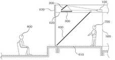
도 3을 참조하여 본 발명에 따른 투명호일을 이용한 프로젝션 시스템의 기본적인 구성을 설명하면 다음과 같다.Referring to Figure 3 describes the basic configuration of a projection system using a transparent foil according to the present invention.
본 실시예에 따른 투명호일을 이용한 프로젝션 시스템은 프로젝터(100), 거울(200), 프로젝션 패널(300), 투명호일(400)을 포함하여 구성된다.The projection system using the transparent foil according to the present embodiment includes a
상기 프로젝터(100)는 영상을 확대하여 출사하는 장치로서, 무대의 천정(620)에 설치되어 관객들에게는 보이지 않는다.The
상기 거울(200)은 프로젝터(100)에서 방출되는 영상을 아래쪽으로 반사시키는 역할을 한다. 상기 거울(200)은 프로젝터(100)에서 방출되는 영상이 모두 전반사되도록 하는 것이 바람직하며, 거울(200)의 위치 및 각도는 무대 세팅에 따라 적절하게 설정하도록 한다.The
상기 거울(200)을 통해 반사된 영상은 상기 프로젝션 패널(300)에 초점이 맞추어 진다. 또한, 상기 프로젝션 패널(300)을 통과한 영상은 더욱 확대되어 상기 투명호일(400)에 의하여 반사되어 무대 전방에 있는 관객(800)으로 향하게 된다.The image reflected through the
본 실시예에서 상기 투명호일(400)은 아래쪽으로 갈수록 무대 전방으로 향하게 경사진 형태로 설치되므로 공연자(700)는 넓은 무대공간을 확보할 수 있게 되어 활동영역이 넓어진다. 상기 투명호일(400)은 45°각도로 설치되는 것이 바람직하다.In the present embodiment, since the
무대 후방에는 스크린(500)이 설치되고, 관객(800)은 프로젝터(100)에서 방출되는 영상과 무대 위에 실제로 존재하는 공연자(700)를 동시에 보게 되어 어느 것이 실물이고 어느 것이 영상인지 잘 구분할 수 없으며, 변화무쌍한 무대를 관람할 수 있다.The
다음으로, 도 4를 참조하면, 본 실시예에서 프로젝션 패널 및 투명호일은 무대의 앞뒤로 나란히 두 개가 설치되고 무대 상부에는 다면거울(210)이 설치된다.Next, referring to FIG. 4, in the present embodiment, two projection panels and a transparent foil are installed side by side before and after the stage, and a
즉, 프로젝터(100)에서 방출된 영상은 다면거울(210)에 의해 반사되어 제1프로젝션 패널(310) 또는 제2프로젝션 패널(320)으로 향하게 된다. 상기 다면거울(210)은 원기둥 형태의 거울을 가공하여 다면체 형상으로 제작된 것으로서, 모터(미도시)에 의하여 고속으로 회전을 하며 회전각도에 따라 반사각도가 달라져 프로젝터(100)에서 방출된 영상이 제1프로젝션 패널(310) 또는 제2프로젝션 패널(320)로 입사하게 된다.That is, the image emitted from the
이때, 상기 프로젝터(100)에서는 두 가지의 영상이 교대로 반복되어 방출되도록 설정되며, 제어부(미도시)에 의하여 상기 다면거울(210)이 일정각도에 위치하였을 때 해당 영상을 방출한다.At this time, the
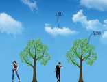
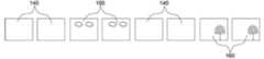
구체적으로, 상기 다면거울(210)을 회전시키는 모터는 스텝모터인 것이 바람직하며, 다면거울(210)은 상기 스텝모터에 의하여 일정각도마다 순간적으로 정지하며 고속으로 회전한다. 이때, 프로젝터(100)에서는 도 5의 구름영상(120) 및 나무영상(130)이 상기 다면거울(210)의 회전각도에 따라 따로따로 교대로 방출된다. 즉, 도 6a와 같이 제1프로젝션패널(310)로 반사되는 각도에서 상기 프로젝터(100)에서는 나무영상(130)이 방출되고, 도 6b와 같이 제2프로젝션패널(320)로 반사되는 각도에서 상기 프로젝터(100)에서는 구름영상(120)이 방출된다. 상기 프로젝터(100)에서 방출되는 영상프레임은 도 7과 같이 물체가 표현되지 않는 프레임(140), 구름이 표현되는 프레임(150) 및 나무가 표현되는 프레임(160)으로 구성될 수 있으며, 각 프레임은 다면거울(210)의 회전각도에 따라 번갈아 가며 방출된다.Specifically, the motor for rotating the
이러한 방법으로 나무영상(130)은 제1투명호일(410)에 의해 반사되어 관객들에게 보여지고, 구름영상(120)은 제2투명호일(420)에 의해 반사되어 관객들에게 보여지게 된다. 따라서, 관객들은 구름과 나무 사이에도 입체감 있는 배경을 볼 수 있게 되어 시각적인 효과가 뛰어나게 된다.In this manner, the
다음으로, 도 8을 참조하여 투명호일의 설치구조에 대하여 설명한다.Next, the installation structure of the transparent foil is demonstrated with reference to FIG.
상기 투명호일은 권취봉(410)에 의해 감겨 있으며, 상기 권취봉(410)의 양단에는 회전롤러(420)가 구비된다. 또한, 상기 회전롤러(420)의 바깥쪽에는 지지부(430)가 구비된다. 상기 지지부(430)는 권취봉(410)이 회전가능하게 결합되면서 무대의 천정에 고정결합된다. 즉, 상기 지지부(430)와 권취봉(410)은 베어링을 매개로 하여 회전가능하게 결합될 수 있다.The transparent foil is wound by a winding
한편, 상기 권취봉(430)에는 톱니(440)가 형성되어 있으며, 상기 지지부(430)에 힌지등으로 회전가능하게 결합된 걸쇠(450)가 상기 톱니(440)에 맞물리도록 구비된다.On the other hand, the take-up
상기 지지부(430)는 회전롤러(420)와 착탈가능하게 제작될 수 있으며, 이때 상기 회전롤러(420)에는 손잡이를 설치하여 권취봉(410)을 돌릴 수 있도록 하는 것이 바람직하다. 원하는 만큼 권취봉(410)을 돌린 다음 지지부(430)를 회전롤러(420)에 끼워 고정시킬 수 있다.The
즉, 상기 걸쇠(450)가 톱니(440)에 맞물려 있지 않은 경우에는 상기 권취봉(410)은 회전가능하며, 상기 걸쇠(450)가 톱니(440)에 맞물려 있는 경우에는 상기 권취봉(410)은 회전 불가능한 상태로 된다.That is, when the
또한, 상기 회전롤러(420)와 지지부(430)의 결합은 육각형 등의 다각형 형상의 돌기로 끼워 결합하여 권취봉(410)이 헛돌지 않게 하는 것이 바람직하다.In addition, the combination of the
상기 투명호일(400)의 밑에는 받침대(460)에 의하여 고정되며, 위에는 권취봉(410)이 회전가능하게 구비된다. 무대에 상기 투명호일(400)을 설치할 때에는 회전롤러(420)를 돌려 투명호일(400)이 팽팽하게 적당한 길이로 펴지게 한 다음 지지부(430)를 끼우고 걸쇠(450)를 톱니(440)에 걸어 권취봉(410)이 더 이상 회전되지 않게 고정시킨다.A bottom of the
상기 지지부(430)가 회전롤러(420)와 일체형으로 제작되는 경우에는 권취봉(410)의 끝단을 스패너 등으로 회전시켜 투명호일(400)을 팽팽하게 한 다음 걸쇠를 톱니(440)에 걸어 고정시킬 수 있다.When the
다음으로, 다른 실시예로서 도 9를 참조하면 프로젝터(100) 및 거울(200)은 무대의 바닥에 설치되고 무대의 천정에 반사판(300)이 설치된다. 상기 반사판(300)은 여러가지 형태로 설치될 수 있으며, 예를 들어 거울이 될 수도 있고 흰색 페인트를 칠 한 면이 될 수도 있다. 그리고, 투명호일(400)은 위쪽으로 갈수록 무대 후방으로 경사지도록 설치된다. 이러한 구조에서 프로젝터(100)에 의하여 방출된 영상은 거울(200)에 의하여 반사된 다음 천정에 설치된 반사판(300) 의하여 반사된 후 투명호일(400)에 의하여 무대 전방에 앉아있는 관객들이 영상을 볼 수 있다.Next, referring to FIG. 9 as another embodiment, the
이러한 구조에 의하여 실제 무대에서 공연을 하는 공연자나 설명을 하는 설명자는 더 넓은 무대공간을 사용할 수 있어 효율적인 공연이 될 수 있다.By this structure, the performer or performer who explains on the actual stage can use a wider stage space and thus can be an efficient performance.
한편, 도 10을 참조하면, 투명호일(400)은 앞에서 보았을 때 오목한 곡면으로 형성된다. 즉, 상기 투명호일(400)은 가운데 부분이 좌우 양 끝단보다 뒤쪽으로 구부러진 형태로 설치된다. 이때, 프로젝터(100)에서 방출되는 영상은 상기 곡면으로 굽어진 투명호일(400)에 대응하여 도 11과 같이 왜곡된 화면으로 제작된다. 이러한 구조의 프로젝션 시스템은 원근감을 더해 주므로 3차원 입체화면시 더욱 입체감을 살릴 수가 있다.Meanwhile, referring to FIG. 10, the
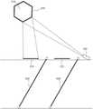
다음, 도 12를 참조하여 홀로그램 장치를 설명하면, 본 발명은 상부에 디스플레이유닛(150)이 설치되고, 상기 디스플레이유닛(150)의 하부에 원추형 투명반사유닛(470)이 설치된다. 상기 원추형 투명반사유닛(470)은 투명호일(400)과 동일한 재질로 제작될 수도 있으며, 투명한 아크릴로 제작될 수도 있다. 또한, 상기 디스플레이유닛(150)은 LCD 등 박막형 디스플레이유닛으로 구성될 수 있다.Next, the hologram device will be described with reference to FIG. 12. In the present invention, a
상기 디스플레이유닛(150)에서 방사된 영상은 상기 원추형 투명반사유닛(470)에 의하여 반사되어 측면에서 바라보는 관객들에게 입체감 있게 전달된다. 이때, 상기 디스플레이유닛(150)에서 방사되는 영상은 평면에 의해 반사되는 것이 아니므로 정상적인 평면영상을 방사하면 원추형 투명반사유닛(470)에 의하여 관객들에게 왜곡된 영상이 보이게 된다. 따라서, 디스플레이유닛(150)에서는 반사면에 따른 왜곡값을 미리 계산하여 역으로 왜곡을 주어야 한다.The image emitted from the
즉, 본 실시예에서 상기 디스플레이유닛(150)에서는 도 13과 같이 원뿔의 꼭지점을 중심으로 펼쳐진 전개도와 같은 형상으로 왜곡된 영상이 방사된다. 이렇게 왜곡된 영상은 상기 원추형 투명반사유닛(470)에 의하여 관객들에게 반사되어 관객들은 마치 상기 원추형 투명반사유닛(470) 내부에 물체가 있는 것처럼 느끼게 된다. 특히, 본 발명에 의한 원추형 투명반사유닛(470)은 각진 모서리가 없으므로 360°회전시 어디서나 매끄러운 입체영상을 제공할 수 있다.That is, in the present embodiment, the
이러한 영상을 제작하려면 4면에서 16면까지 다면 렌더링작업을 수행해야 한다. 또한, 카메라로 실사 촬영할 경우에는 4대에서 16대의 카메라로 동시에 촬영한다. 이렇게 촬영된 영상은 도 13과 같이 왜곡된 영상으로 변환되어 결합하는 과정을 거치게 된다.In order to produce such an image, four- to six-sided rendering must be performed. In addition, when shooting live with a camera, four to sixteen cameras simultaneously shoot. The captured image is converted into a distorted image as shown in FIG. 13 and then combined.
100 : 프로젝터 200 : 거울
210 : 다각형 거울 300 : 프로젝션 패널
400 : 투명호일 410 : 권취봉
420 : 회전롤러 430 : 지지부
440 : 톱니 450 : 걸쇠
500 : 스크린 610 : 무대바닥
620 : 천정무대세트 630 : 커튼
700 : 공연자 800 : 관객100: projector 200: mirror
210: polygon mirror 300: projection panel
400: transparent foil 410: winding rod
420: rotating roller 430: support
440: tooth 450: latch
500: screen 610: stage floor
620: ceiling stage set 630: curtain
700: Performer 800: Audience
Claims (6)
Translated fromKorean상기 프로젝션 시스템은 무대 상부에 구비되어 영상을 방출하는 프로젝터;
일정 각도 기울어져 상기 프로젝터에서 방출되는 영상을 하부로 반사하는 거울;
상기 거울로부터 반사된 영상이 맺히는 프로젝션 패널;
상기 프로젝션 패널을 통과한 빛을 반사시키는 투명호일을 포함하여 구성되며,
상기 프로젝션 패널 및 투명호일은 복수 개 구비되고
상기 거울은 회전하는 다각형 거울로 구비되며,
상기 프로젝터는 상기 다각형 거울의 회전각도에 대응하여 복수 개의 영상이 번갈아 가며 방출되어 상기 프로젝션 패널로 각각 입사되는 것을 특징으로 하는 투명호일을 이용한 프로젝션 시스템.In a projection system using transparent foil,
The projection system includes a projector provided on the upper stage to emit an image;
A mirror inclined at an angle to reflect an image emitted from the projector downward;
A projection panel on which an image reflected from the mirror is formed;
It comprises a transparent foil that reflects the light passing through the projection panel,
The projection panel and the transparent foil is provided with a plurality
The mirror is provided with a rotating polygon mirror,
The projector is a projection system using a transparent foil, characterized in that a plurality of images are alternately emitted corresponding to the rotation angle of the polygon mirror and incident to the projection panel.
상기 투명호일을 이용한 프로젝션 시스템은
상기 투명호일이 감기는 권취봉;
상기 권취봉의 일단에 구비된 톱니;
상기 권취봉을 회전가능하도록 지지하는 지지부; 및
상기 지지부에 회전가능하게 결합되어 상기 톱니에 맞물리도록 설치된 걸쇠부를 포함하는 것을 특징으로 한 투명호일을 이용한 프로젝션 시스템.In a projection system using a transparent foil in which the image emitted from the projector is reflected through the transparent foil so that the audience in front can see,
The projection system using the transparent foil
A winding rod to which the transparent foil is wound;
Teeth provided at one end of the winding rod;
A support part rotatably supporting the winding rod; And
Projection system using a transparent foil, characterized in that it comprises a latch portion rotatably coupled to the support portion to be engaged with the teeth.
상기 프로젝션 시스템은 무대 바닥에 구비되어 영상을 방출하는 프로젝터;
일정 각도 기울어져 상기 프로젝터에서 방출되는 영상을 무대 상부로 반사하는 거울;
무대 천정에 구비되어 상기 거울로부터 반사된 영상을 다시 아래 방향으로 반사시키는 반사판;
상기 반사판에 의해 반사된 영상을 무대 전방으로 반사시키는 투명호일을 포함하여 구성되며,
상기 투명호일은 가운데 부분이 좌우 양 끝단보다 뒤쪽으로 구부러진 형태로 설치되며, 상기 프로젝터는 상기 투명호일의 형태에 대응한 왜곡된 영상을 방사하는 것을 특징으로 하는 투명호일을 이용한 프로젝션 시스템.In a projection system using transparent foil,
The projection system includes a projector provided on the stage floor to emit an image;
A mirror inclined at an angle and reflecting an image emitted from the projector to an upper stage;
A reflection plate provided on the stage ceiling and reflecting the image reflected from the mirror downward again;
It comprises a transparent foil for reflecting the image reflected by the reflector to the front of the stage,
The transparent foil is installed in a shape in which a center portion is bent backwards from both left and right ends, and the projector emits a distorted image corresponding to the shape of the transparent foil.
상기 투명호일은 가운데 부분이 좌우 양 끝단보다 뒤쪽으로 구부러진 형태로 설치되며, 상기 프로젝터는 상기 투명호일의 형태에 대응한 왜곡된 영상을 방사하는 것을 특징으로 하는 투명호일을 이용한 프로젝션 시스템.The method of claim 1,
The transparent foil is installed in a shape in which a center portion is bent backwards from both left and right ends, and the projector emits a distorted image corresponding to the shape of the transparent foil.
Priority Applications (1)
| Application Number | Priority Date | Filing Date | Title |
|---|---|---|---|
| KR1020110064233AKR101283295B1 (en) | 2011-06-30 | 2011-06-30 | Projection system using transparent foil |
Applications Claiming Priority (1)
| Application Number | Priority Date | Filing Date | Title |
|---|---|---|---|
| KR1020110064233AKR101283295B1 (en) | 2011-06-30 | 2011-06-30 | Projection system using transparent foil |
Related Child Applications (1)
| Application Number | Title | Priority Date | Filing Date |
|---|---|---|---|
| KR1020120142722ADivisionKR20130014457A (en) | 2012-12-10 | 2012-12-10 | Display apparatus for 3 dimensional image |
Publications (2)
| Publication Number | Publication Date |
|---|---|
| KR20130003145A KR20130003145A (en) | 2013-01-09 |
| KR101283295B1true KR101283295B1 (en) | 2013-07-11 |
Family
ID=47835462
Family Applications (1)
| Application Number | Title | Priority Date | Filing Date |
|---|---|---|---|
| KR1020110064233AActiveKR101283295B1 (en) | 2011-06-30 | 2011-06-30 | Projection system using transparent foil |
Country Status (1)
| Country | Link |
|---|---|
| KR (1) | KR101283295B1 (en) |
Families Citing this family (10)
| Publication number | Priority date | Publication date | Assignee | Title |
|---|---|---|---|---|
| GB2532230B (en)* | 2014-11-12 | 2018-05-23 | De Monfort Univ | Projection Screen Apparatus |
| KR101686135B1 (en) | 2015-04-28 | 2016-12-13 | 이관준 | Hologram stage setting |
| KR20170039879A (en) | 2015-10-02 | 2017-04-12 | (주)리플렉션3D | Projection screen for projection device and projection device having the projection screen |
| KR102233432B1 (en)* | 2016-01-12 | 2021-03-30 | (주)디스트릭트홀딩스 | Apparatus and method for image projection using holography |
| KR101858248B1 (en)* | 2016-09-23 | 2018-05-15 | 주식회사 홀로티브글로벌 | Live performance and hologram performances apparatus capable of variable stage |
| KR20160140544A (en) | 2016-11-28 | 2016-12-07 | 이관준 | Hologram stage setting |
| KR20160146599A (en) | 2016-11-29 | 2016-12-21 | 이관준 | Hologram stage setting |
| CN106990663A (en)* | 2017-06-05 | 2017-07-28 | 电子科技大学中山学院 | A portable and foldable three-dimensional household projection device |
| CN107264720A (en)* | 2017-06-27 | 2017-10-20 | 广船国际有限公司 | A kind of ship bulkhead structure |
| KR101860680B1 (en)* | 2017-09-01 | 2018-06-29 | 한국과학기술원 | Method and apparatus for implementing 3d augmented presentation |
Citations (2)
| Publication number | Priority date | Publication date | Assignee | Title |
|---|---|---|---|---|
| JPH10509535A (en)* | 1995-09-20 | 1998-09-14 | マース・ウーヴェ | A device that displays moving images on the background of the stage |
| KR200314445Y1 (en)* | 2003-02-27 | 2003-05-27 | 배근화 | Three-dimensional image displayer |
- 2011
- 2011-06-30KRKR1020110064233Apatent/KR101283295B1/enactiveActive
Patent Citations (2)
| Publication number | Priority date | Publication date | Assignee | Title |
|---|---|---|---|---|
| JPH10509535A (en)* | 1995-09-20 | 1998-09-14 | マース・ウーヴェ | A device that displays moving images on the background of the stage |
| KR200314445Y1 (en)* | 2003-02-27 | 2003-05-27 | 배근화 | Three-dimensional image displayer |
Also Published As
| Publication number | Publication date |
|---|---|
| KR20130003145A (en) | 2013-01-09 |
Similar Documents
| Publication | Publication Date | Title |
|---|---|---|
| KR101283295B1 (en) | Projection system using transparent foil | |
| US10191364B2 (en) | Device and method for omnidirectional image display | |
| US9849399B2 (en) | Background imagery for enhanced pepper's ghost illusion | |
| CA2579205C (en) | Projection apparatus and method for pepper's ghost illusion | |
| US20160360167A1 (en) | Output light monitoring for benchmarking and enhanced control of a display system | |
| US20160139562A1 (en) | Enhanced pepper's ghost illusion using video panel displays | |
| US9904066B2 (en) | Methods and systems for manfucaturing a rear projection screen and a setup for displaying a simulated 3D hologram | |
| US10384144B2 (en) | Travel case for portable Pepper's Ghost Illusion setup | |
| WO2017073095A1 (en) | Image projection device, stage installation, and image projection method | |
| US9989775B2 (en) | Dual-sided pepper's ghost illusion | |
| US10067353B2 (en) | Foil tensioning system for pepper's ghost illusion | |
| JP6583954B2 (en) | Exhibition apparatus and video display method | |
| GB2437928A (en) | Projection apparatus | |
| EP4325118A1 (en) | Simulated fireplace | |
| KR20130014457A (en) | Display apparatus for 3 dimensional image | |
| US4095882A (en) | Projected image display system | |
| US9645404B2 (en) | Low-profile bounce chamber for Pepper's Ghost Illusion | |
| RU101643U1 (en) | DEVICE FOR CREATING ILLUSION DEPTH SCENE | |
| KR20160003089U (en) | Arrangement of the image projection device for stage setting | |
| JP2016099617A (en) | Reflection type projection display system |
Legal Events
| Date | Code | Title | Description |
|---|---|---|---|
| A201 | Request for examination | ||
| PA0109 | Patent application | Patent event code:PA01091R01D Comment text:Patent Application Patent event date:20110630 | |
| PA0201 | Request for examination | ||
| N231 | Notification of change of applicant | ||
| PN2301 | Change of applicant | Patent event date:20120611 Comment text:Notification of Change of Applicant Patent event code:PN23011R01D | |
| E902 | Notification of reason for refusal | ||
| PE0902 | Notice of grounds for rejection | Comment text:Notification of reason for refusal Patent event date:20120918 Patent event code:PE09021S01D | |
| A107 | Divisional application of patent | ||
| PA0107 | Divisional application | Comment text:Divisional Application of Patent Patent event date:20121210 Patent event code:PA01071R01D | |
| PG1501 | Laying open of application | ||
| E701 | Decision to grant or registration of patent right | ||
| PE0701 | Decision of registration | Patent event code:PE07011S01D Comment text:Decision to Grant Registration Patent event date:20130405 | |
| GRNT | Written decision to grant | ||
| PR0701 | Registration of establishment | Comment text:Registration of Establishment Patent event date:20130701 Patent event code:PR07011E01D | |
| PR1002 | Payment of registration fee | Payment date:20130701 End annual number:3 Start annual number:1 | |
| PG1601 | Publication of registration | ||
| FPAY | Annual fee payment | Payment date:20170627 Year of fee payment:5 | |
| PR1001 | Payment of annual fee | Payment date:20170627 Start annual number:5 End annual number:5 | |
| FPAY | Annual fee payment | Payment date:20180910 Year of fee payment:6 | |
| PR1001 | Payment of annual fee | Payment date:20180910 Start annual number:6 End annual number:6 | |
| FPAY | Annual fee payment | Payment date:20190731 Year of fee payment:7 | |
| PR1001 | Payment of annual fee | Payment date:20190731 Start annual number:7 End annual number:7 | |
| PR1001 | Payment of annual fee | Payment date:20240507 Start annual number:12 End annual number:12 |