KR101283229B1 - COOLING STRUCTURE FOR Environmental-friendly VEHICLE - Google Patents
COOLING STRUCTURE FOR Environmental-friendly VEHICLEDownload PDFInfo
- Publication number
- KR101283229B1 KR101283229B1KR1020110058536AKR20110058536AKR101283229B1KR 101283229 B1KR101283229 B1KR 101283229B1KR 1020110058536 AKR1020110058536 AKR 1020110058536AKR 20110058536 AKR20110058536 AKR 20110058536AKR 101283229 B1KR101283229 B1KR 101283229B1
- Authority
- KR
- South Korea
- Prior art keywords
- battery
- duct
- air
- vehicle
- cooling structure
- Prior art date
- Legal status (The legal status is an assumption and is not a legal conclusion. Google has not performed a legal analysis and makes no representation as to the accuracy of the status listed.)
- Active
Links
- 238000001816coolingMethods0.000titleclaimsabstractdescription70
- 238000000034methodMethods0.000claims3
- 238000005516engineering processMethods0.000description2
- 238000005273aerationMethods0.000description1
- 230000005540biological transmissionEffects0.000description1
- 238000007664blowingMethods0.000description1
- 238000009434installationMethods0.000description1
- 238000011144upstream manufacturingMethods0.000description1
Images


Classifications
- B—PERFORMING OPERATIONS; TRANSPORTING
- B60—VEHICLES IN GENERAL
- B60K—ARRANGEMENT OR MOUNTING OF PROPULSION UNITS OR OF TRANSMISSIONS IN VEHICLES; ARRANGEMENT OR MOUNTING OF PLURAL DIVERSE PRIME-MOVERS IN VEHICLES; AUXILIARY DRIVES FOR VEHICLES; INSTRUMENTATION OR DASHBOARDS FOR VEHICLES; ARRANGEMENTS IN CONNECTION WITH COOLING, AIR INTAKE, GAS EXHAUST OR FUEL SUPPLY OF PROPULSION UNITS IN VEHICLES
- B60K1/00—Arrangement or mounting of electrical propulsion units
- B60K1/04—Arrangement or mounting of electrical propulsion units of the electric storage means for propulsion
- H—ELECTRICITY
- H01—ELECTRIC ELEMENTS
- H01M—PROCESSES OR MEANS, e.g. BATTERIES, FOR THE DIRECT CONVERSION OF CHEMICAL ENERGY INTO ELECTRICAL ENERGY
- H01M10/00—Secondary cells; Manufacture thereof
- H01M10/60—Heating or cooling; Temperature control
- H01M10/65—Means for temperature control structurally associated with the cells
- H01M10/656—Means for temperature control structurally associated with the cells characterised by the type of heat-exchange fluid
- H01M10/6561—Gases
- H01M10/6563—Gases with forced flow, e.g. by blowers
- H—ELECTRICITY
- H01—ELECTRIC ELEMENTS
- H01M—PROCESSES OR MEANS, e.g. BATTERIES, FOR THE DIRECT CONVERSION OF CHEMICAL ENERGY INTO ELECTRICAL ENERGY
- H01M10/00—Secondary cells; Manufacture thereof
- H01M10/60—Heating or cooling; Temperature control
- H01M10/61—Types of temperature control
- H01M10/613—Cooling or keeping cold
- H—ELECTRICITY
- H01—ELECTRIC ELEMENTS
- H01M—PROCESSES OR MEANS, e.g. BATTERIES, FOR THE DIRECT CONVERSION OF CHEMICAL ENERGY INTO ELECTRICAL ENERGY
- H01M10/00—Secondary cells; Manufacture thereof
- H01M10/60—Heating or cooling; Temperature control
- H01M10/62—Heating or cooling; Temperature control specially adapted for specific applications
- H01M10/625—Vehicles
- B—PERFORMING OPERATIONS; TRANSPORTING
- B60—VEHICLES IN GENERAL
- B60K—ARRANGEMENT OR MOUNTING OF PROPULSION UNITS OR OF TRANSMISSIONS IN VEHICLES; ARRANGEMENT OR MOUNTING OF PLURAL DIVERSE PRIME-MOVERS IN VEHICLES; AUXILIARY DRIVES FOR VEHICLES; INSTRUMENTATION OR DASHBOARDS FOR VEHICLES; ARRANGEMENTS IN CONNECTION WITH COOLING, AIR INTAKE, GAS EXHAUST OR FUEL SUPPLY OF PROPULSION UNITS IN VEHICLES
- B60K11/00—Arrangement in connection with cooling of propulsion units
- B60K11/06—Arrangement in connection with cooling of propulsion units with air cooling
- B—PERFORMING OPERATIONS; TRANSPORTING
- B60—VEHICLES IN GENERAL
- B60K—ARRANGEMENT OR MOUNTING OF PROPULSION UNITS OR OF TRANSMISSIONS IN VEHICLES; ARRANGEMENT OR MOUNTING OF PLURAL DIVERSE PRIME-MOVERS IN VEHICLES; AUXILIARY DRIVES FOR VEHICLES; INSTRUMENTATION OR DASHBOARDS FOR VEHICLES; ARRANGEMENTS IN CONNECTION WITH COOLING, AIR INTAKE, GAS EXHAUST OR FUEL SUPPLY OF PROPULSION UNITS IN VEHICLES
- B60K1/00—Arrangement or mounting of electrical propulsion units
- B60K2001/003—Arrangement or mounting of electrical propulsion units with means for cooling the electrical propulsion units
- B60K2001/005—Arrangement or mounting of electrical propulsion units with means for cooling the electrical propulsion units the electric storage means
- B—PERFORMING OPERATIONS; TRANSPORTING
- B60—VEHICLES IN GENERAL
- B60K—ARRANGEMENT OR MOUNTING OF PROPULSION UNITS OR OF TRANSMISSIONS IN VEHICLES; ARRANGEMENT OR MOUNTING OF PLURAL DIVERSE PRIME-MOVERS IN VEHICLES; AUXILIARY DRIVES FOR VEHICLES; INSTRUMENTATION OR DASHBOARDS FOR VEHICLES; ARRANGEMENTS IN CONNECTION WITH COOLING, AIR INTAKE, GAS EXHAUST OR FUEL SUPPLY OF PROPULSION UNITS IN VEHICLES
- B60K1/00—Arrangement or mounting of electrical propulsion units
- B60K1/04—Arrangement or mounting of electrical propulsion units of the electric storage means for propulsion
- B60K2001/0405—Arrangement or mounting of electrical propulsion units of the electric storage means for propulsion characterised by their position
- B60K2001/0416—Arrangement in the rear part of the vehicle
- B—PERFORMING OPERATIONS; TRANSPORTING
- B60—VEHICLES IN GENERAL
- B60K—ARRANGEMENT OR MOUNTING OF PROPULSION UNITS OR OF TRANSMISSIONS IN VEHICLES; ARRANGEMENT OR MOUNTING OF PLURAL DIVERSE PRIME-MOVERS IN VEHICLES; AUXILIARY DRIVES FOR VEHICLES; INSTRUMENTATION OR DASHBOARDS FOR VEHICLES; ARRANGEMENTS IN CONNECTION WITH COOLING, AIR INTAKE, GAS EXHAUST OR FUEL SUPPLY OF PROPULSION UNITS IN VEHICLES
- B60K1/00—Arrangement or mounting of electrical propulsion units
- B60K1/04—Arrangement or mounting of electrical propulsion units of the electric storage means for propulsion
- B60K2001/0405—Arrangement or mounting of electrical propulsion units of the electric storage means for propulsion characterised by their position
- B60K2001/045—Arrangement in a wheel, e.g. a spare wheel
- Y—GENERAL TAGGING OF NEW TECHNOLOGICAL DEVELOPMENTS; GENERAL TAGGING OF CROSS-SECTIONAL TECHNOLOGIES SPANNING OVER SEVERAL SECTIONS OF THE IPC; TECHNICAL SUBJECTS COVERED BY FORMER USPC CROSS-REFERENCE ART COLLECTIONS [XRACs] AND DIGESTS
- Y02—TECHNOLOGIES OR APPLICATIONS FOR MITIGATION OR ADAPTATION AGAINST CLIMATE CHANGE
- Y02E—REDUCTION OF GREENHOUSE GAS [GHG] EMISSIONS, RELATED TO ENERGY GENERATION, TRANSMISSION OR DISTRIBUTION
- Y02E60/00—Enabling technologies; Technologies with a potential or indirect contribution to GHG emissions mitigation
- Y02E60/10—Energy storage using batteries
Landscapes
- Engineering & Computer Science (AREA)
- Chemical & Material Sciences (AREA)
- Manufacturing & Machinery (AREA)
- Chemical Kinetics & Catalysis (AREA)
- Electrochemistry (AREA)
- General Chemical & Material Sciences (AREA)
- Combustion & Propulsion (AREA)
- Transportation (AREA)
- Mechanical Engineering (AREA)
- Cooling, Air Intake And Gas Exhaust, And Fuel Tank Arrangements In Propulsion Units (AREA)
- Arrangement Or Mounting Of Propulsion Units For Vehicles (AREA)
- Body Structure For Vehicles (AREA)
Abstract
Translated fromKoreanDescription
Translated fromKorean본 발명은 친환경 자동차의 배터리 냉각구조에 관한 것으로서, 더욱 상세하게는 친환경 자동차의 배터리를 트렁크의 타이어 웰의 내부에 탑재하고, 분기된 냉각공기를 공급되도록 하여 친환경 자동차의 배터리를 냉각시키는 친환경 자동차의 배터리 냉각구조에 관한 것이다.The present invention relates to a battery cooling structure of an environmentally friendly vehicle, and more particularly, to an environmentally friendly vehicle that mounts a battery of an environmentally friendly vehicle in a tire well of a trunk and supplies branched cooling air to cool the battery of the environmentally friendly vehicle. It relates to a battery cooling structure.
전기자동차, 하이브리드 자동차 등과 같은 친환경 자동차에는 차량의 동력원인 모터에 전원을 공급하기 위해 고정압 배터리가 장착된다.Eco-friendly vehicles, such as electric vehicles and hybrid vehicles, are equipped with a fixed voltage battery to supply power to a motor that is the vehicle's power source.
상기 배터리는 친환경 자동차의 차량 내부에 장착되는 바, 장착위치에 따라 실내 공간의 확보, 이로 인한 상품성 등에 영향을 미치게 된다.The battery is mounted inside the vehicle of the eco-friendly car, and thus affects the securing of indoor space and the merchandise thereof according to the mounting position.
예컨대, 트렁크내의 리어플로우의 상부에 배터리를 탑재하는 예 등이 제시되어 있다.For example, an example of mounting a battery on top of a rear flow in a trunk is presented.
한편, 상기와 같이, 친환경 자동차에 탑재된 배터리는 작동에 따라 발열이 되는데, 이를 냉각시키는 기술도 중요한 요소로 작용하고 있다.On the other hand, as described above, the battery mounted in the eco-friendly car is heat generated by the operation, the cooling technology also acts as an important factor.
종래기술에 따른 친환경 자동차의 배터리 냉각구조를 살펴보면, 차량의 실내 또는 트렁크의 일측에 배터리를 탑재하지만 별도의 냉각모듈이 없거나, 단순히 송풍에 의해서 배터리를 냉각시키는 기술이 제안되었다.Looking at the battery cooling structure of the environmentally friendly vehicle according to the prior art, a technology for mounting the battery in the interior or the trunk of the vehicle but there is no separate cooling module, or simply by cooling the battery has been proposed.
이러한 종래기술에 따른 친환경 자동차의 배터리 냉각구조를 살펴보면, 단순히 공기의 흐름을 가이드 하는 덕트와, 공기를 유동시키는 냉각팬으로 이루어지는 경우가 많다. 상기의 친환경 자동차의 배터리 냉각구조에 따르면, 단지 덕트와 냉각팬을 설치하여 효과적으로 냉각공기를 유동을 제어하지 못하는 문제점이 있다.Looking at the battery cooling structure of the environmentally friendly vehicle according to the prior art, it is often made of a duct to guide the flow of air, and a cooling fan for flowing the air. According to the battery cooling structure of the eco-friendly vehicle, there is a problem that can not effectively control the flow of cooling air by installing only a duct and a cooling fan.
또한, 배터리가 장착되는 공간에 의해 차량의 실내가 협소해지거나, 차량의 트렁크가 좁아지는 문제점도 있다.In addition, there is a problem that the interior of the vehicle is narrowed or the trunk of the vehicle is narrowed due to the space in which the battery is mounted.
본 발명은 상기와 같은 문제점을 해결하기 위해 발명된 것으로서, 친환경 자동차의 배터리를 구성하는 배터리팩을 타이어 웰의 내부에 병렬로 배치하고, 차량의 실내로부터 유입된 냉각공기를 분기하여 독립된 유로로 각 배터리팩으로 송풍함으로써 냉각 공기의 유동시 발생하는 압력 손실을 최소화하도록 하는 친환경 자동차의 냉각구조를 제공하는데 있다.The present invention has been invented to solve the above problems, the battery pack constituting the battery of the environmentally friendly vehicle is arranged in parallel in the interior of the tire well, branching the cooling air flowed from the interior of the vehicle into a separate flow path It is to provide a cooling structure of an eco-friendly vehicle to minimize the pressure loss generated during the flow of cooling air by blowing to the battery pack.
상기와 같은 목적을 달성하기 위한 본 발명에 따른 친환경 자동차의 냉각구조는, 친환경 자동차의 배터리 냉각구조에 있어서, 모터에 전원을 공급하는 복수의 배터리팩이 타이어 웰의 내부에서 일정거리를 두고 이격되어 병렬로 배치되고, 차량의 실내의 공기가 유입되도록 차량 실내와 연통되게 구비되는 유입덕트와, 상기 유입덕트의 후단에서 이격되게 배치된 배터리팩에 각각 독립적으로 공기를 공급할 수 있도록 상기 배터리팩과 동수로 분기되는 분기덕트와, 상기 배터리팩의 하부에 배치되어 분기된 공기의 유동을 합기시키는 하부덕트와, 상기 하부덕트의 후단에 구비되어 공기를 외부로 배출시키는 냉각팬을 포함하는 것을 특징으로 한다.In the cooling structure of the eco-friendly vehicle according to the present invention for achieving the above object, in the battery cooling structure of the environmentally friendly vehicle, a plurality of battery packs for supplying power to the motor is spaced apart from the inside of the tire well at a certain distance Arranged in parallel, the inlet duct provided in communication with the vehicle interior so that the air in the interior of the vehicle, and the same number as the battery pack so that the air can be independently supplied to each of the battery pack spaced apart from the rear end of the inlet duct A branch duct branched to the lower duct, a lower duct arranged at a lower portion of the battery pack to agitate the flow of branched air, and a cooling fan provided at a rear end of the lower duct to discharge the air to the outside. .
여기서, 상기 유입덕트는, 각 배터리팩으로 연결되는 분기덕트로 병렬 분기되는 것이 바람직하다.Here, the inlet duct is preferably branched in parallel to the branch duct connected to each battery pack.
상기 배터리팩은 트렁크의 타이어 웰의 전방에 장착되는 것을 특징으로 한다.The battery pack is characterized in that it is mounted to the front of the tire well of the trunk.
한편, 상기 유입덕트는 차량의 2열시트 측면으로 연결되도록 한다.On the other hand, the inlet duct is to be connected to the side of the second row seat of the vehicle.
아울러, 상기 냉각팬의 후방으로 LDC(Low voltage Dc-dc Converter)가 배치되고, 상기 LDC의 후방으로 트렁크에 연결되는 배출덕트가 구비되는 것이 바람직하다.In addition, a low voltage DC converter (LDC) is disposed at the rear of the cooling fan, and a discharge duct connected to the trunk at the rear of the LDC is preferably provided.
상기와 같은 본 발명에 따른 친환경 자동차의 냉각구조에 따르면, 차량의 실내로부터 유입된 냉각공기를 분기시켜 각각 배터리 모듈로 공급되도록 함으로써, 덕트 내부에서 유동에 따른 압력강하를 최소화시켜 효율적으로 배터리를 냉각시킬 수 있다.According to the cooling structure of the eco-friendly vehicle according to the present invention as described above, by branching the cooling air introduced from the interior of the vehicle to be supplied to each of the battery module, by minimizing the pressure drop due to the flow in the duct efficiently cooling the battery You can.
특히, 덕트를 병렬로 분기되도록 하여 냉각공기를 각각의 배터리 모듈로 독립된 유로를 통하여 공급되도록 함으로써, 유입한 냉각공기의 온도상승없이 각 배터리 모듈로 공급함으로써 냉각성능이 향상된다.In particular, by allowing the duct to branch in parallel so that the cooling air is supplied to each battery module through an independent flow path, the cooling performance is improved by supplying each battery module without increasing the temperature of the introduced cooling air.
아울러, 친환경 자동차의 배터리를 타이어 웰 내 전방에 배치되도록 함으로써, 배터리 설치에 소요되는 공간을 최소화시켜 차량의 실내 및 트렁크 내부의 공간을 확보함으로써 상품성을 향상시킬 수 있다.In addition, by allowing the battery of the environmentally friendly vehicle to be disposed in front of the tire well, it is possible to minimize the space required for the battery installation to secure the space in the interior and trunk of the vehicle to improve the merchandise.
또한, 차량의 후방에 배터리와 덕트와 같은 구조물이 구비됨으로써, 후방추돌시 충격량을 흡수할 수 있어서 차량의 안정성을 확보할 수 있다.In addition, by providing a structure such as a battery and a duct in the rear of the vehicle, it is possible to absorb the impact amount during the rear collision can ensure the stability of the vehicle.
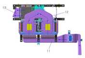
도 1 및 도 2는 본 발명에 따른 친환경 자동차의 배터리 냉각구조를 도시한 사시도,
도 3은 본 발명에 따른 친환경 자동차의 배터리 냉각구조를 도시한 우측면도,
도 4는 본 발명에 따른 친환경 자동차의 배터리 냉각구조를 도시한 저면도,
도 5는 본 발명에 따른 친환경 자동차의 배터리 냉각구조에서 유입덕트의 위치를 도시한 사시도,
도 6은 본 발명에 따른 친환경 자동차의 배터리 냉각구조에 의한 공기 유동을 보여주는 도면.1 and 2 are a perspective view showing a battery cooling structure of the eco-friendly vehicle according to the present invention,
3 is a right side view showing a battery cooling structure of an eco-friendly vehicle according to the present invention;
Figure 4 is a bottom view showing a battery cooling structure of the environmentally friendly vehicle according to the invention,
5 is a perspective view showing the position of the inlet duct in the battery cooling structure of the eco-friendly vehicle according to the present invention,
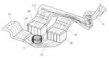
Figure 6 is a view showing the air flow by the battery cooling structure of the environmentally friendly vehicle according to the invention.
이하, 첨부된 도면을 참조로 하여 본 발명의 일 실시예에 따른 친환경 자동차의 배터리 냉각구조에 대하여 상세히 설명하기로 한다.
Hereinafter, a battery cooling structure of an eco-friendly vehicle according to an embodiment of the present invention will be described in detail with reference to the accompanying drawings.
도 1 내지 도 5에 도시된 바와 같이, 본 발명의 친환경 자동차의 배터리 냉각구조는 복수의 배터리 모듈을 트렁크 내부의 타이어 웰의 전방에 배치하고, 차량의 실내와 연결되는 유입덕트(11)와, 상기 유입덕트(11)에서 각 배터리팩(BP)으로 병렬분기되는 분기덕트(11a)(11b)와, 각 배터리팩(BP)의 하부에 구비되어 각 배터리팩(BP)을 통과한 냉각공기를 합기시키는 하부덕트(12)와, 상기 하부덕트(12)의 후방에 구비되어 외부로 공기를 배출되는 통로인 배출덕트(13)와, 공기를 유동시키는 냉각팬(13)을 포함한다.As shown in Figure 1 to 5, the battery cooling structure of the eco-friendly vehicle of the present invention is arranged in front of the tire well in the trunk of the plurality of battery modules, the
본 발명에 따른 친환경 자동차의 배터리 냉각구조에서는 모터에 전원을 공급하기 위한 배터리가 복수의 배터리팩(BP)으로 구비되고, 이때 상기 배터리팩(BP)을 차량의 타이어 웰의 내부에 장착되도록 한다. 차량의 트렁크에는 스페어 타이어를 탑재하기 위한 타이어 웰(tire well)이 구비되는 바, 상기 타이어 웰 내부의 공간을 활용하여 배터리 모듈이 장착되도록 한다. 특히 타이어 웰의 내부 전방에 배터리 모듈이 장착되도록 하여, 타이어 웰의 내부에 배터리 모듈과 스페어 타이어가 탑재되도록 한다.In the battery cooling structure of an eco-friendly vehicle according to the present invention, a battery for supplying power to a motor is provided with a plurality of battery packs BP, and the battery pack BP is mounted inside the tire well of the vehicle. A tire well for mounting a spare tire is provided in the trunk of the vehicle, and the battery module is mounted by utilizing a space inside the tire well. In particular, the battery module is mounted in the front of the tire well so that the battery module and the spare tire are mounted in the tire well.
유입덕트(11)는 차량의 실내와 연통되도록 구비된다. 유입덕트(11)의 일측을 차량의 실내측에 위치하고, 타측은 배터리팩(BP)측과 연결되도록 하여, 차량의 실내와 배터리팩(BP)이 서로 연통되는 통로가 되도록 한다.
상기 유입덕트(11)의 일측은 바람직하게는 도 5에 도시된 바와 같이, 2열시트의 측면에 위치하도록 하여 차량의 실내로부터 공기가 유입되도록 하고, 2열시트 후방의 리어패키지 또는 2열시트의 하부에 위치할 수도 있다.One side of the
분기덕트(11a)(11b)는 상기 유입덕트(11)의 후단에 일측이 연결되고, 타측은 배터리팩과 연결된다. 상기 분기덕트(11a)(11b)는 차량의 실내로부터 유입한 공기를 각 배터리팩(BP)으로 독립적인 유로를 형성하여 공급되도록 하기 위한 것으로서, 바람직하게는 타이어 웰(T)의 내부에 장착된 배터리팩(BP)과 동수로 분기된다. 즉, 도 2에서와 같이, 2개의 배터리팩(BP)이 장착된다면 분기덕트(11a)(11b)도 좌우 양측으로 각각 분기되도록 한다.Branch duct (11a) (11b) is one side is connected to the rear end of the
한편, 유입덕트(11)로 유입된 공기를 분기덕트(11a)(11b)를 통하여 분기된 상태로 배터리팩(BP)으로 공급하는 이유는 배터리팩(BP)으로 공급되는 공기의 흐름이 병렬로 분기되도록 함으로써, 덕트 내부의 압력강하에 따른 유동손실을 방지하고, 차량의 실내로부터 유입된 공기를 직접 배터리팩(BP)으로 공급되도록 하기 위함이다.Meanwhile, the reason for supplying the air introduced into the
예컨대, 복수의 배터리팩(BP)이 장착되고, 이들을 하나의 덕트 내부에 위치하도록 하면, 덕트 내부에 배터리팩이 직렬로 배치되는 구조로서, 공기 유동의 하류에 위치하는 배터리팩측의 압력강하로 냉각성능이 떨어지게 된다. 또한, 하류측에 위치한 배터리팩은 상류측에 위치한 배터리팩과 열교환한 공기와 접촉되므로 냉각성능이 저하된다.For example, when a plurality of battery packs BP are mounted and placed in one duct, the battery packs are arranged in series in the duct, and are cooled by a pressure drop on the battery pack side downstream of the air flow. The performance will drop. In addition, since the battery pack located on the downstream side is in contact with the air heat exchanged with the battery pack located on the upstream side, the cooling performance is reduced.
그러나, 본 발명에 따르면, 외부에서 유입된 공기를 병렬로 분기하여 공급함으로써 유로내부에서의 압력강하가 발생하지 않을뿐더러, 유입된 상태의 온도를 유지한 채로 각 배터리팩으로 공급되어 냉각성능을 향상시킨다.However, according to the present invention, by supplying the air flowed in from the outside in parallel, the pressure drop in the flow path does not occur, and is supplied to each battery pack while maintaining the temperature of the inflow state to improve the cooling performance. Let's do it.
하부덕트(12)는 상기 분기덕트(11a)(11b)에 의해서 분기된 공기의 흐름을 합기시키는 역할을 한다. 상기 하부덕트(12)는 상기 분기덕트(11a)(11b)와 달리 상부는 각 배터리팩(BP)과 같은 수로 덕트로 형성되고 이들이 서로 모여 하나의 유로를 형성하도록 한다.The
따라서, 상기 분기덕트(11a)(11b)와 하부덕트(12)의 사이에 각 배터리팩(BP)이 구비됨으로써, 분기덕트(11a)(11b)로부터 공급된 공기가 배터리팩(BP)을 냉각시키고 하부덕트(12)를 통해 배출되는 구조를 갖는다.Therefore, the battery packs BP are provided between the
냉각팬(14)은 상기 하부덕트(12)의 후단에 연결되도록 설치된다. 상기 냉각팬(14)은 상기 유입덕트(11), 분기덕트(11a)(11b) 및 하부덕트(12)의 내부에서 공기의 유동이 발생토록 하기 위한 것으로서, 상기 냉각팬(14)이 공기를 외부로 배출되도록 한다.The
특히, 상기 냉각팬(14)이 유입덕트(11)나 분기덕트(11a)(11b) 쪽이 아닌, 하부덕트(12)의 후방에 설치됨으로써, 냉각팬(14)의 작동에 의한 소음이 차량의 실내로 전해지는 것을 최소화시킬 수 있다.In particular, since the
배출덕트(13)는 상기 냉각팬(14)의 후방에 위치하여, 배터리팩을 냉각시킨 공기를 트렁크로 배출되도록 한다. 상기 배출덕트(13)의 일측은 상기 냉각팬(14)측에 연결되고, 타측은 트렁크에 위치하여, 상기 배출덕트(13)에서 배출된 공기는 트렁크로 유입되고, 트렁크의 배출그릴을 통하여 외부로 배출된다.The
이때, LDC(Low voltage Dc-dc Converter)와 같은 고전압부품을 상기 냉각팬(14)과 배출덕트(13)의 사이에 배치하여, 냉각팬(14)에서 배출된 공기에 의해서 작동에 의해 가열된 고전압부품을 냉각시키도록 한다.
At this time, a high voltage component such as a low voltage dc-dc converter (LDC) is disposed between the
상기와 같은 구성을 갖는 본 발명에 따른 친환경 자동차의 배터리 냉각구조의 작용에 대하여 설명하기로 한다.The operation of the battery cooling structure of the eco-friendly vehicle according to the present invention having the configuration as described above will be described.
타이어 웰에 장착된 배터리 모듈은 모터로 전원을 공급함에 따라 필연적으로 열이 발생한다. 이를 냉각시키기 위해서 냉각팬(14)을 작동시켜 차량 실내의 공기를 배터리팩으로 공급되도록 한다.The battery module mounted in the tire well inevitably generates heat as it is powered by a motor. In order to cool this, the
냉각팬(14)이 작동하면, 유입덕트(11)를 통하여 차량 실내의 공기가 유입되기 시작한다. 유입덕트(11)를 통과한 공기는 분기덕트(11a)(11b)를 통하여 분기되어 각 배터리팩으로 공급한다. 유입덕트(11)로 유입된 공기가 직접 각 배터리팩(BP)으로 공급되는 구조이므로, 다른 배터리팩과 열교환하지 않은 상태로 공급되므로 냉각성능이 향상된다.When the
또한, 본 발명에 따른 친환경 자동차의 배터리 냉각구조에서의 전반적인 공기유동이 도 6에 도시된 바와 같이, 유입덕트(11)로 공급된 공기가 병렬분기되고 분리된 공기의 흐름이 서로 섞이지않고 각 배터리팩에 독립적으로 공급되므로, 유로가 길어짐에 따라 발생하는 압력손실을 줄여 냉각에 필요한 충분한 유량의 공기가 공급되도록 함으로써 냉각성능을 향상시킬 수 있다.In addition, the overall air flow in the battery cooling structure of the eco-friendly vehicle according to the present invention as shown in Figure 6, the air supplied to the
분기덕트(11a)(11b)에서 각 배터리팩으로 공기가 공급되면 발열된 배터리팩(BP)은 냉각되고 하부덕트(12)로 유입된다. 하부덕트(12)는 분기된 공기의 유동을 합기시켜 외부로 배출시킨다.When air is supplied from the
하부덕트(12)에서 배출된 공기는 냉각팬(14)을 지나 LDC와 같은 고전압부품으로 유입됨으로써, 작동에 따른 고전압부품을 냉각시킨다.The air discharged from the
배터리팩(BP), 고전압부품을 냉각시킨 공기는 배출덕트(13)를 통하여 트렁크로 배출되고, 트렁크의 배출그릴을 통하여 차량의 외부로 배출된다.The air cooling the battery pack BP and the high voltage component is discharged to the trunk through the
11 : 유입덕트 11a, 11b : 분기덕트
12 : 하부덕트 13 : 배출덕트
14 : 냉각팬 BP : 배터리 모듈11:
12: lower duct 13: discharge duct
14: cooling fan BP: battery module
Claims (5)
Translated fromKorean모터에 전원을 공급하는 복수의 배터리팩이 타이어 웰의 내부에서 일정거리를 두고 이격되어 병렬로 배치되고,
차량 실내의 공기가 유입되도록 차량 실내와 연통되게 구비되는 유입덕트와,
상기 유입덕트의 후단에서 이격되게 배치된 배터리팩에 각각 독립적으로 공기를 공급할 수 있도록 상기 배터리팩과 동수로 분기되는 분기덕트와,
상기 배터리팩의 하부에 배치되어 분기된 공기의 유동을 합기시키는 하부덕트와,
상기 하부덕트의 후단에 구비되어 공기를 외부로 배출시키는 냉각팬을 포함하고,
상기 냉각팬의 후방으로 LDC(Low voltage Dc-dc Converter)가 배치되고,
상기 LDC의 후방으로 트렁크에 연결되는 배출덕트가 구비되는 것을 특징으로 하는 친환경 자동차의 배터리 냉각구조.In the battery cooling structure of an eco-friendly car,
A plurality of battery packs for supplying power to the motor are arranged in parallel, spaced apart at a certain distance inside the tire well,
An inlet duct provided in communication with the vehicle interior such that air in the vehicle is introduced;
A branching duct branched into the same number as the battery pack so as to independently supply air to the battery packs spaced apart from the rear end of the inflow duct;
A lower duct disposed under the battery pack to agitate the flow of branched air;
A cooling fan provided at a rear end of the lower duct to discharge air to the outside;
A low voltage DC converter (LDC) is disposed at the rear of the cooling fan.
Battery cooling structure of an eco-friendly vehicle, characterized in that the exhaust duct is connected to the trunk to the rear of the LDC.
상기 유입덕트는,
각 배터리팩으로 연결되는 분기덕트로 병렬 분기되는 것을 특징으로 하는 친환경 자동차의 배터리 냉각구조.The method of claim 1,
The inlet duct,
Battery cooling structure of an eco-friendly car, characterized in that the branched in parallel with the branch duct connected to each battery pack.
상기 배터리팩은 트렁크의 타이어 웰의 전방에 장착되는 것을 특징으로 하는 친환경 자동차의 배터리 냉각구조.The method of claim 1,
The battery pack is a battery cooling structure of an eco-friendly vehicle, characterized in that mounted to the front of the tire well of the trunk.
상기 유입덕트는 차량의 2열시트 측면으로 연결되는 것을 특징으로 하는 친환경 자동차의 배터리 냉각구조.The method of claim 1,
The inlet duct is a battery cooling structure of an eco-friendly vehicle, characterized in that connected to the second row seat side of the vehicle.
Priority Applications (4)
| Application Number | Priority Date | Filing Date | Title |
|---|---|---|---|
| KR1020110058536AKR101283229B1 (en) | 2011-06-16 | 2011-06-16 | COOLING STRUCTURE FOR Environmental-friendly VEHICLE |
| JP2011197372AJP2013001383A (en) | 2011-06-16 | 2011-09-09 | Battery cooling structure of eco-friendly vehicle |
| US13/281,623US8794361B2 (en) | 2011-06-16 | 2011-10-26 | Cooling structure for environmental-friendly vehicle |
| DE102011085945ADE102011085945A1 (en) | 2011-06-16 | 2011-11-08 | Cooling arrangement for an environmentally friendly vehicle |
Applications Claiming Priority (1)
| Application Number | Priority Date | Filing Date | Title |
|---|---|---|---|
| KR1020110058536AKR101283229B1 (en) | 2011-06-16 | 2011-06-16 | COOLING STRUCTURE FOR Environmental-friendly VEHICLE |
Publications (2)
| Publication Number | Publication Date |
|---|---|
| KR20120139024A KR20120139024A (en) | 2012-12-27 |
| KR101283229B1true KR101283229B1 (en) | 2013-07-11 |
Family
ID=47228348
Family Applications (1)
| Application Number | Title | Priority Date | Filing Date |
|---|---|---|---|
| KR1020110058536AActiveKR101283229B1 (en) | 2011-06-16 | 2011-06-16 | COOLING STRUCTURE FOR Environmental-friendly VEHICLE |
Country Status (4)
| Country | Link |
|---|---|
| US (1) | US8794361B2 (en) |
| JP (1) | JP2013001383A (en) |
| KR (1) | KR101283229B1 (en) |
| DE (1) | DE102011085945A1 (en) |
Families Citing this family (27)
| Publication number | Priority date | Publication date | Assignee | Title |
|---|---|---|---|---|
| DE112011101677B4 (en)* | 2010-05-19 | 2019-06-27 | Suzuki Motor Corporation | Installation structure for electrical equipment in rear vehicle body |
| EP2909053B1 (en) | 2012-10-19 | 2019-09-25 | Agility Fuel Systems LLC | System and method for mounting a fuel system |
| JP5827615B2 (en)* | 2012-12-27 | 2015-12-02 | トヨタ紡織株式会社 | Exhaust structure for vehicles |
| JP6107929B2 (en)* | 2013-03-22 | 2017-04-05 | トヨタ自動車株式会社 | Temperature control structure |
| US9067486B2 (en) | 2013-08-30 | 2015-06-30 | Ford Global Technologies, Llc | Air cooling system for high voltage battery cell arrays |
| US9302573B2 (en)* | 2013-08-30 | 2016-04-05 | Ford Global Technologies, Llc | Duct for high voltage battery air cooling exhaust and recirculation |
| US9016412B2 (en)* | 2013-08-30 | 2015-04-28 | Ford Global Technologies, Llc | Duct to influence air cooling distribution to battery module and DC/DC module |
| FR3041906B1 (en)* | 2015-10-05 | 2017-11-03 | Renault Sas | BATTERY SUPPORT ARRANGEMENT FOR A HYBRID VEHICLE. |
| KR101762276B1 (en)* | 2016-01-26 | 2017-07-28 | 현대자동차주식회사 | Mounting structure of battery and spare tire for vehicle |
| KR102599387B1 (en)* | 2016-12-15 | 2023-11-09 | 현대자동차주식회사 | Cooling structure of battery system for electric vehicles |
| CN108081941A (en)* | 2018-01-24 | 2018-05-29 | 北京长安汽车工程技术研究有限责任公司 | A kind of accumulator installation assembly |
| JP7047419B2 (en)* | 2018-02-01 | 2022-04-05 | トヨタ自動車株式会社 | Vehicle cooler device |
| EP3840972B1 (en) | 2018-08-24 | 2024-09-11 | Hexagon Purus North America Holdings Inc. | Battery system for heavy duty vehicles |
| US11548352B2 (en)* | 2018-10-12 | 2023-01-10 | Fca Us Llc | Interior trim storage bin/tray with integrated exhauster path |
| CN111232058A (en)* | 2018-11-28 | 2020-06-05 | 长城汽车股份有限公司 | Electric automobile front cabin structure and vehicle |
| MX2021012601A (en) | 2019-04-19 | 2022-01-18 | Hexagon Purus North America Holdings Inc | ELECTRIC MOTORPROPULSION SYSTEM FOR HEAVY VEHICLES. |
| MX2021012598A (en)* | 2019-04-19 | 2023-03-16 | Hexagon Purus North America Holdings Inc | Electric front end accessory devices assembly. |
| KR102699011B1 (en)* | 2019-11-14 | 2024-08-23 | 현대자동차주식회사 | Battery system of vehicle |
| CA3161967A1 (en) | 2019-11-26 | 2021-06-03 | Hexagon Purus North America Holdings Inc. | Electric vehicle power distribution and drive control modules |
| US11926207B2 (en) | 2020-10-09 | 2024-03-12 | Hexagon Purus North America Holdings Inc. | Battery and auxiliary components for vehicle trailer |
| CA3205080A1 (en) | 2020-12-11 | 2022-06-16 | Hexagon Purus North America Holdings Inc. | Trailer hookup breakaway mitigation systems and methods |
| JP7697800B2 (en)* | 2021-03-17 | 2025-06-24 | 株式会社Subaru | Protective structure of automotive batteries |
| KR102691486B1 (en) | 2021-08-25 | 2024-08-05 | 주식회사 동희산업 | Vehicle battery pack cooling structure |
| KR20230031058A (en) | 2021-08-26 | 2023-03-07 | 주식회사 동희산업 | Vehicle battery pack cooling structure |
| KR20240006266A (en) | 2022-07-06 | 2024-01-15 | 주식회사 동희산업 | Battery pack of vehicle |
| KR20240006267A (en) | 2022-07-06 | 2024-01-15 | 주식회사 동희산업 | Battery pack of vehicle |
| KR20240047122A (en)* | 2022-10-04 | 2024-04-12 | 현대자동차주식회사 | Vehicle body structure |
Citations (4)
| Publication number | Priority date | Publication date | Assignee | Title |
|---|---|---|---|---|
| JP2004022267A (en) | 2002-06-14 | 2004-01-22 | Honda Motor Co Ltd | Battery cooling structure |
| KR20060036694A (en)* | 2004-10-26 | 2006-05-02 | 주식회사 엘지화학 | Battery pack cooling system |
| KR100633910B1 (en)* | 2005-09-12 | 2006-10-16 | 현대자동차주식회사 | Battery mounting structure of car |
| JP2009154696A (en)* | 2007-12-26 | 2009-07-16 | Calsonic Kansei Corp | Cooling device for heating element |
Family Cites Families (11)
| Publication number | Priority date | Publication date | Assignee | Title |
|---|---|---|---|---|
| JP3975990B2 (en) | 2003-09-17 | 2007-09-12 | 日産自動車株式会社 | Vehicle battery cooling control device |
| KR20060124862A (en) | 2005-05-26 | 2006-12-06 | 한라공조주식회사 | Car Battery Cooler |
| JP4274165B2 (en)* | 2005-10-06 | 2009-06-03 | トヨタ自動車株式会社 | Cooling device for on-vehicle equipment |
| JP4845571B2 (en)* | 2006-04-05 | 2011-12-28 | 本田技研工業株式会社 | Vehicle power supply |
| JP2007276668A (en)* | 2006-04-07 | 2007-10-25 | Toyota Motor Corp | duct |
| JP2007331689A (en) | 2006-06-19 | 2007-12-27 | Nissan Motor Co Ltd | Battery cooling device for vehicle |
| CN102050009B (en)* | 2006-09-07 | 2013-03-13 | 本田技研工业株式会社 | Electrical device cooling structure in vehicle |
| JP4390802B2 (en)* | 2006-12-15 | 2009-12-24 | トヨタ自動車株式会社 | In-vehicle battery cooling structure |
| KR100851121B1 (en) | 2007-09-13 | 2008-08-08 | 현대자동차주식회사 | Package case for electronic parts of hybrid vehicle |
| JP5330876B2 (en)* | 2009-03-26 | 2013-10-30 | 本田技研工業株式会社 | Battery module |
| JP2010244802A (en)* | 2009-04-03 | 2010-10-28 | Honda Motor Co Ltd | Battery cooling structure |
- 2011
- 2011-06-16KRKR1020110058536Apatent/KR101283229B1/enactiveActive
- 2011-09-09JPJP2011197372Apatent/JP2013001383A/enactivePending
- 2011-10-26USUS13/281,623patent/US8794361B2/enactiveActive
- 2011-11-08DEDE102011085945Apatent/DE102011085945A1/enactivePending
Patent Citations (4)
| Publication number | Priority date | Publication date | Assignee | Title |
|---|---|---|---|---|
| JP2004022267A (en) | 2002-06-14 | 2004-01-22 | Honda Motor Co Ltd | Battery cooling structure |
| KR20060036694A (en)* | 2004-10-26 | 2006-05-02 | 주식회사 엘지화학 | Battery pack cooling system |
| KR100633910B1 (en)* | 2005-09-12 | 2006-10-16 | 현대자동차주식회사 | Battery mounting structure of car |
| JP2009154696A (en)* | 2007-12-26 | 2009-07-16 | Calsonic Kansei Corp | Cooling device for heating element |
Also Published As
| Publication number | Publication date |
|---|---|
| US20120318591A1 (en) | 2012-12-20 |
| KR20120139024A (en) | 2012-12-27 |
| JP2013001383A (en) | 2013-01-07 |
| DE102011085945A1 (en) | 2012-12-20 |
| US8794361B2 (en) | 2014-08-05 |
Similar Documents
| Publication | Publication Date | Title |
|---|---|---|
| KR101283229B1 (en) | COOLING STRUCTURE FOR Environmental-friendly VEHICLE | |
| KR20120136923A (en) | Cooling structure for electric vehicle | |
| US8556017B2 (en) | Vehicular power supply system | |
| US9160042B2 (en) | Battery pack for electric vehicle and battery pack mounting structure | |
| KR102264771B1 (en) | Battery pack | |
| JP5277362B1 (en) | In-vehicle structure of battery pack | |
| US10106025B2 (en) | High voltage battery cooling plenum | |
| CN107662483B (en) | vehicle construction | |
| JP6387422B2 (en) | Vehicle power supply | |
| JP4385020B2 (en) | Vehicle power supply | |
| KR101316432B1 (en) | Battery pack mounting structure of vehicle | |
| US20170334309A1 (en) | Cooling structure for battery pack | |
| CN103764424B (en) | Vehicle and be equipped on the cooling construction of supply unit of vehicle | |
| US8887844B2 (en) | Vehicle having an electric drive device | |
| JPWO2013161010A1 (en) | Vehicle cooling device | |
| JP2014075181A (en) | Battery pack for vehicles | |
| CN101389502A (en) | power supply | |
| KR102819316B1 (en) | Battery case mounting structure for electric vehicle | |
| JP2013107420A (en) | Cooling system for vehicular battery | |
| JP5843177B2 (en) | Battery pack for electric vehicles | |
| CN111204200A (en) | Battery cooling device | |
| WO2022224947A1 (en) | Cooling device | |
| JP2013035323A (en) | Cooling structure of vehicular power supply device | |
| JP2022149588A (en) | Battery pack cooling structure | |
| US20120328928A1 (en) | Battery cooling structure of vehicle |
Legal Events
| Date | Code | Title | Description |
|---|---|---|---|
| A201 | Request for examination | ||
| PA0109 | Patent application | Patent event code:PA01091R01D Comment text:Patent Application Patent event date:20110616 | |
| PA0201 | Request for examination | ||
| E902 | Notification of reason for refusal | ||
| PE0902 | Notice of grounds for rejection | Comment text:Notification of reason for refusal Patent event date:20121122 Patent event code:PE09021S01D | |
| PG1501 | Laying open of application | ||
| E701 | Decision to grant or registration of patent right | ||
| PE0701 | Decision of registration | Patent event code:PE07011S01D Comment text:Decision to Grant Registration Patent event date:20130530 | |
| GRNT | Written decision to grant | ||
| PR0701 | Registration of establishment | Comment text:Registration of Establishment Patent event date:20130701 Patent event code:PR07011E01D | |
| PR1002 | Payment of registration fee | Payment date:20130701 End annual number:3 Start annual number:1 | |
| PG1601 | Publication of registration | ||
| FPAY | Annual fee payment | Payment date:20160630 Year of fee payment:4 | |
| PR1001 | Payment of annual fee | Payment date:20160630 Start annual number:4 End annual number:4 | |
| FPAY | Annual fee payment | Payment date:20180628 Year of fee payment:6 | |
| PR1001 | Payment of annual fee | Payment date:20180628 Start annual number:6 End annual number:6 | |
| PR1001 | Payment of annual fee | Payment date:20200629 Start annual number:8 End annual number:8 | |
| PR1001 | Payment of annual fee | Payment date:20210628 Start annual number:9 End annual number:9 | |
| PR1001 | Payment of annual fee | Payment date:20220627 Start annual number:10 End annual number:12 |