KR101280647B1 - Cable trough system - Google Patents
Cable trough systemDownload PDFInfo
- Publication number
- KR101280647B1 KR101280647B1KR1020087011017AKR20087011017AKR101280647B1KR 101280647 B1KR101280647 B1KR 101280647B1KR 1020087011017 AKR1020087011017 AKR 1020087011017AKR 20087011017 AKR20087011017 AKR 20087011017AKR 101280647 B1KR101280647 B1KR 101280647B1
- Authority
- KR
- South Korea
- Prior art keywords
- sections
- base
- cable
- view
- coupler
- Prior art date
- Legal status (The legal status is an assumption and is not a legal conclusion. Google has not performed a legal analysis and makes no representation as to the accuracy of the status listed.)
- Expired - Fee Related
Links
Images


Classifications
- G—PHYSICS
- G02—OPTICS
- G02B—OPTICAL ELEMENTS, SYSTEMS OR APPARATUS
- G02B6/00—Light guides; Structural details of arrangements comprising light guides and other optical elements, e.g. couplings
- G02B6/46—Processes or apparatus adapted for installing or repairing optical fibres or optical cables
- H—ELECTRICITY
- H02—GENERATION; CONVERSION OR DISTRIBUTION OF ELECTRIC POWER
- H02G—INSTALLATION OF ELECTRIC CABLES OR LINES, OR OF COMBINED OPTICAL AND ELECTRIC CABLES OR LINES
- H02G3/00—Installations of electric cables or lines or protective tubing therefor in or on buildings, equivalent structures or vehicles
- H02G3/02—Details
- H02G3/06—Joints for connecting lengths of protective tubing or channels, to each other or to casings, e.g. to distribution boxes; Ensuring electrical continuity in the joint
- H02G3/0608—Joints for connecting non cylindrical conduits, e.g. channels
- G—PHYSICS
- G02—OPTICS
- G02B—OPTICAL ELEMENTS, SYSTEMS OR APPARATUS
- G02B6/00—Light guides; Structural details of arrangements comprising light guides and other optical elements, e.g. couplings
- G02B6/44—Mechanical structures for providing tensile strength and external protection for fibres, e.g. optical transmission cables
- G02B6/4439—Auxiliary devices
- G02B6/4459—Ducts; Conduits; Hollow tubes for air blown fibres
- H—ELECTRICITY
- H02—GENERATION; CONVERSION OR DISTRIBUTION OF ELECTRIC POWER
- H02G—INSTALLATION OF ELECTRIC CABLES OR LINES, OR OF COMBINED OPTICAL AND ELECTRIC CABLES OR LINES
- H02G3/00—Installations of electric cables or lines or protective tubing therefor in or on buildings, equivalent structures or vehicles
- H02G3/02—Details
- H02G3/04—Protective tubing or conduits, e.g. cable ladders or cable troughs
- H02G3/0437—Channels
- H—ELECTRICITY
- H02—GENERATION; CONVERSION OR DISTRIBUTION OF ELECTRIC POWER
- H02G—INSTALLATION OF ELECTRIC CABLES OR LINES, OR OF COMBINED OPTICAL AND ELECTRIC CABLES OR LINES
- H02G3/00—Installations of electric cables or lines or protective tubing therefor in or on buildings, equivalent structures or vehicles
- H02G3/02—Details
- H02G3/04—Protective tubing or conduits, e.g. cable ladders or cable troughs
- H02G3/0456—Ladders or other supports
- Y—GENERAL TAGGING OF NEW TECHNOLOGICAL DEVELOPMENTS; GENERAL TAGGING OF CROSS-SECTIONAL TECHNOLOGIES SPANNING OVER SEVERAL SECTIONS OF THE IPC; TECHNICAL SUBJECTS COVERED BY FORMER USPC CROSS-REFERENCE ART COLLECTIONS [XRACs] AND DIGESTS
- Y10—TECHNICAL SUBJECTS COVERED BY FORMER USPC
- Y10T—TECHNICAL SUBJECTS COVERED BY FORMER US CLASSIFICATION
- Y10T29/00—Metal working
- Y10T29/49—Method of mechanical manufacture
- Y10T29/49826—Assembling or joining
- Y10T29/49863—Assembling or joining with prestressing of part
- Y10T29/49876—Assembling or joining with prestressing of part by snap fit
Landscapes
- Engineering & Computer Science (AREA)
- Architecture (AREA)
- Civil Engineering (AREA)
- Structural Engineering (AREA)
- Physics & Mathematics (AREA)
- General Physics & Mathematics (AREA)
- Optics & Photonics (AREA)
- Laying Of Electric Cables Or Lines Outside (AREA)
- Installation Of Indoor Wiring (AREA)
- Connector Housings Or Holding Contact Members (AREA)
- Details Of Indoor Wiring (AREA)
Abstract
Translated fromKorean
Description
Translated fromKorean본 출원은 통신 케이블과 같은 케이블의 관리 및 안내를 위한 시스템에 관한 것이다. 더 구체적으로는, 본 발명은 상기 시스템을 위한 트로프 (trough), 피팅, 및 커플링에 관한 것이다.The present application relates to a system for the management and guidance of cables, such as communication cables. More specifically, the present invention relates to troughs, fittings, and couplings for such systems.
통신 산업에서, 신호 전달을 위한 광섬유의 사용이 가속화되고 있다. 광섬유 시스템의 이용이 증가하고 있으므로, 산업계는 광섬유 케이블 관리에 주목해야 한다.In the telecommunications industry, the use of optical fibers for signal transmission is accelerating. As the use of fiber optic systems is increasing, the industry should pay attention to fiber cable management.
필요한 광섬유 관리의 한 영역은 장비의 일부로부터 다른 부분으로 광섬유를 안내하는 것이다. 예컨대, 통신 설비에서, 광섬유 케이블은 섬유 분배 장비와 광 회선 단말 장비 사이에서 안내될 수도 있다. 이러한 장비를 지닌 건물 및 다른 구조물에서, 케이블 안내는 케이블을 일 위치에서 다른 위치로 안내하기 위해 감춰진 천장 영역에서 일어날 수 있다. 또한, 구리 케이블, 혼합 케이블 또는 다른 전달 케이블은 적절한 관리 및 보호가 필요하다.One area of fiber management that is required is to guide fiber from one piece of equipment to another. For example, in a telecommunications facility, fiber optic cables may be guided between fiber distribution equipment and optical line terminal equipment. In buildings and other structures with such equipment, cable guidance may occur in concealed ceiling areas to guide cables from one location to another. In addition, copper cables, mixed cables or other transfer cables require proper care and protection.
광섬유를 안내할 때, 안내 시스템은 쉽게 조립되며, 장비 요건의 변화에 쉽게 이용되고 적응될 수 있는 것이 바람직하다. 따라서, 이러한 안내 시스템은 케이블 안내 경로를 형성하기 위한 커플링 및 트로프와 같은 복수의 트로프 부재를 포함한다. 트로프 시스템 부재는 커플링에 의해 함께 결합된다. 1991년 11월 26일자로 Henneberger 등에게 허여된 미국특허 5,067,678 호는 복수의 트로프 및 피팅을 포함하는 케이블 안내 시스템에 관한 것이다. '678 특허는 트로프 부재 및 피팅을 결합하기 위한 커플링 ('678 특허의 도 1 의 요소 (250)) 을 더 개시한다. '678 특허의 도 6 ~ 도 7 을 참조하면, 트로프 부재를 결합하기 위한 복수의 하드웨어가 개시되어 있다. 미국특허 제 5,316,243 호; 제 5,752,781 호 및 제 6,715,719 호는 커플링의 다른 예를 도시한다.When guiding an optical fiber, it is desirable that the guiding system be easily assembled and can be easily used and adapted to changing equipment requirements. Thus, such a guide system includes a plurality of trough members, such as couplings and troughs, to form a cable guide path. The trough system members are joined together by a coupling. U.S. Patent 5,067,678 to Henneberger et al. On November 26, 1991, relates to a cable guidance system comprising a plurality of troughs and fittings. The '678 patent further discloses a coupling (element 250 of FIG. 1 of the' 678 patent) for joining the trough member and the fitting. 6-7 of the '678 patent, a plurality of hardware for engaging a trough member is disclosed. US Patent No. 5,316,243; 5,752,781 and 6,715,719 show other examples of couplings.
미국특허 제 6,631,875 호는 시스템을 조립하기 위해 함께 결합되는 다양한 별개의 구성품을 구비하는 케이블 트로프 시스템을 도시한다.U. S. Patent No. 6,631, 875 shows a cable trough system having various separate components that are joined together to assemble the system.
케이블 안내 시스템에는, 트로프, 커플링, 및 피팅의 제조 및 설치의 용이성, 및 시스템의 케이블의 수를 취급하기 위한 시스템 구성품의 크기의 적절성을 포함하는 몇몇 관심사가 있다. 점점더 큰 조밀도가 요구됨에 따라, 시스템을 통해 지나가는 케이블을 위한 충분한 공간을 갖는 것은 특별한 관심사이다.Cable guidance systems have several concerns, including ease of manufacture and installation of troughs, couplings, and fittings, and adequacy of the size of system components to handle the number of cables in the system. As ever greater density is required, it is of particular interest to have enough space for cables to pass through the system.
통신 케이블 관리 시스템은 케이블 안내 및 관리를 위한 평평한 상부면 및 측면을 포함하는 트로프 요소를 포함한다. 한가지 바람직한 실시예에서, 트로프 요소는 함께 조립되는 별개의 부품으로 만들어진다. 한가지 바람직한 실시예에서, 부품을 함께 조립하기 위해 결합 장치가 사용된다. 결합 장치는 예컨대 부품을 함께 스냅결합해서 현장에서 시스템이 조립될 수 있게 한다. 그 다음, 트로프 요소는 케이블 관리 시스템을 형성하도록 함께 조립된다.The communications cable management system includes a trough element that includes flat top and side surfaces for cable guidance and management. In one preferred embodiment, the trough elements are made of separate parts that are assembled together. In one preferred embodiment, a joining device is used to assemble the parts together. The coupling device, for example, snaps the parts together so that the system can be assembled on site. The trough elements are then assembled together to form a cable management system.
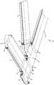
도 1 은 본 발명에 따른 통신 케이블 관리 시스템의 평면사시도이다.1 is a top perspective view of a communication cable management system according to the present invention.
도 2 는 도 1 의 시스템의 종방향 트로프 부재의 평면사시도이다.FIG. 2 is a top perspective view of the longitudinal trough member of the system of FIG. 1. FIG.
도 3 은 도 2 의 트로프 부재의 단부도이다.3 is an end view of the trough member of FIG. 2.
도 4 는 도 2 및 도 3 의 종방향 트로프 부재의 섹션 사이의 결합 장치의 확대도이다.4 is an enlarged view of the coupling device between the sections of the longitudinal trough member of FIGS. 2 and 3.
도 5 는 결합 작용 동안의 섹션을 도시하는 도 4 의 도면과 같은 도면이다.5 is a view like that of FIG. 4 showing a section during the engagement action.
도 6 은 도 1 의 시스템의 커플러의 평면사시도이다.6 is a top perspective view of a coupler of the system of FIG. 1.
도 7 은 도 1 의 시스템의 십자형 구성품의 평면도이다.7 is a plan view of the cruciform components of the system of FIG.
도 8 은 도 7 의 십자형 구성품의 측면도이다.8 is a side view of the cross-shaped component of FIG. 7.
도 9 는 도 7 의 십자형 구성품의 배면도이다.FIG. 9 is a rear view of the cross component of FIG. 7. FIG.
도 10 은 도 9 의 도면의 확대도이다.10 is an enlarged view of the view of FIG. 9.
도 11 은 십자형 구성품의 두 섹션 사이의 결합 장치의 측단면도이다.11 is a side sectional view of a coupling device between two sections of a cruciform component.
도 12 는 나머지로부터 분리된 두 개의 섹션을 도시하는 도 7 의 십자형 구성품의 평면사시도이다.12 is a top perspective view of the cross-shaped component of FIG. 7 showing two sections separated from the rest.
도 13 은 도 12 의 도면의 확대도이다.FIG. 13 is an enlarged view of the view of FIG. 12.
도 14 는 도 7 의 십자형 구성품의 섹션 중 하나의 평면 사시도이다.14 is a top perspective view of one of the sections of the cross-shaped component of FIG. 7.
도 15 는 도 14 의 섹션의 배면사시도이다.FIG. 15 is a rear perspective view of the section of FIG. 14. FIG.
도 16 은 도 14 의 섹션의 평면도이다.16 is a top view of the section of FIG. 14.
도 17 은 도 14 의 섹션의 배면도이다.17 is a rear view of the section of FIG. 14.
도 18 은 도 14 의 섹션의 제 1 측면도이다.18 is a first side view of the section of FIG. 14.
도 19 는 도 14 의 섹션의 다른 측면도이다.19 is another side view of the section of FIG. 14;
도 20 은 도 1 의 시스템의 T자형 구성품의 평면도이다.20 is a plan view of a T-shaped component of the system of FIG.
도 21 은 도 20 의 T자형 구성품의 제 1 측면도이다.FIG. 21 is a first side view of the T-shaped component of FIG. 20.
도 22 는 도 20 의 T자형 구성품의 다른 측면도이다.FIG. 22 is another side view of the T-shaped component of FIG. 20.
도 23 은 나머지로부터 분리된 하나의 섹션을 도시하는 도 20 의 T자형 구성품의 평면사시도이다.FIG. 23 is a top perspective view of the T-shaped component of FIG. 20 showing one section separated from the rest.
도 24 는 도 23 의 도면의 확대도이다.24 is an enlarged view of the view of FIG. 23.
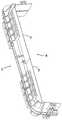
도 25 는 도 1 의 시스템의 L자형 구성품의 평면사시도이다.25 is a top perspective view of the L-shaped component of the system of FIG. 1.
도 26 은 도 25 의 L자형 구성품의 평면도이다.FIG. 26 is a plan view of the L-shaped component of FIG. 25.
도 27 은 도 25 의 L자형 구성품의 측면도이다.FIG. 27 is a side view of the L-shaped component of FIG. 25.
도 28 은 도 1 의 시스템의 축소부 구성품의 평면사시도이다.FIG. 28 is a top perspective view of the reduced component of the system of FIG. 1. FIG.
도 29 는 커플러의 대안적인 실시예의 평면사시도이다.29 is a top perspective view of an alternative embodiment of the coupler.
도 30 은 커플러의 다른 대안적인 실시예의 평면사시도이다.30 is a top perspective view of another alternative embodiment of the coupler.
도 31 은 도 30 의 커플러의 배면사시도이다.FIG. 31 is a rear perspective view of the coupler of FIG. 30.
도 32 는 도 30 및 도 31 의 커플러의 일부의 분해 사시도이다.32 is an exploded perspective view of a portion of the coupler of FIGS. 30 and 31.
도 33 은 도 30 및 도 31 의 커플러의 섹션 중 하나의 제 1 배면사시도이다.33 is a first rear perspective view of one of the sections of the coupler of FIGS. 30 and 31.
도 34 는 도 33 의 섹션의 다른 배면 사시도이다.FIG. 34 is another rear perspective view of the section of FIG. 33; FIG.
본 발명은 종래 기술의 케이블 관리 시스템보다 제조성 및 맞춤생산성이 향 상된 케이블 관리 시스템에 관한 것이다. 본 발명의 일 양태는 케이블 관리 시스템을 형성하도록 함께 조립되는 트로프 구성품으로 조립되는 섹션의 사용이다. 다양한 구성품 및 구성이 본 발명에 따라 가능하다. 구성품 및 구성의 다양한 실시예가 도 1 ~ 도 34 에 도시되어 있다. 그러나, 수많은 다른 구성품 및 구성이 가능하다.The present invention relates to a cable management system that is more productive and customizable than the cable management system of the prior art. One aspect of the present invention is the use of sections assembled into trough components that are assembled together to form a cable management system. Various components and configurations are possible in accordance with the present invention. Various embodiments of components and configurations are shown in FIGS. 1-34. However, many other components and configurations are possible.
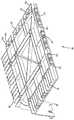
도 1 을 참조하면, 케이블 관리를 위한 시스템 (10) 이 시스템 (10) 의 케이블에 연결되는 일련의 커넥터 또는 다른 통신 장비를 포함할 수 있는 캐비닛, 프레임, 베이 (bay) 또는 다른 장비 (비도시) 위에 위치되어 있다. 시스템 (10) 은 다양한 브래킷 및 하드웨어에 의해 천장에 매달리거나 장비에 장착된다.Referring to FIG. 1, a cabinet, frame, bay, or other device (not shown) in which the
실시예의 시스템 (10) 은 광섬유 케이블을 지탱하고 관리하기 위한 케이블 경로를 함께 형성하는 다양한 트로프 요소를 포함한다. 시스템 (10) 은 종방향 트로프 부재 (14), 및 종방향 트로프 부재 (14) 를 십자형 구성품 (18), T자형 구성품 (20), L자형 구성품 (22), 및 축소부 (24) 를 포함하는 다른 트로프 요소에 연결하기 위한 커플러 (16) 를 포함한다. 시스템 (10) 은 다른 구성품 (14, 16, 18, 20, 22, 24) 을 부가함으로써 다양한 방향으로 확장될 수 있다. 상기 구성품에 대해, 상기 모든 구성품보다 적은 구성품 또는 추가적인 구성품을 사용하는 구성을 포함하는 다른 구성이 가능하다. 예컨대, 트로프 구성품 아래에 있는 장비로의 하방 이동을 위해 케이블이 트로프 구성품에 들어가고 나올 수 있도록 케이블 출구 트로프가 부가될 수 있다. 개시내용이 본 발명에 참조로 관련되어 있는 미국특허 제 6,625,373 호는 측방 트로프 부재 (14) 에 장착될 수 있는 예시 적인 케이블 출구 트로프를 나타낸다.The
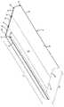
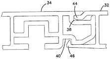
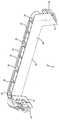
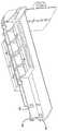
도 2 ~ 도 5 를 참조하면, 종방향 트로프 부재 (14) 는 연속적인 단면을 갖는 것이 바람직하며, 원하는 길이 (L1) 로 절단될 수 있다. 종방향 트로프 부재 (14) 는 압출 공정에 의해 만들어지는 것이 바람직하다. 도시되어 있는 바와 같이, 종방향 트로프 부재 (14) 는 종방향 트로프 부재 (14) 를 형성하도록 함께 조립되는 별개의 섹션으로 이루어져 있다. 결합 장치 (30) 가 별개의 측부 (32) 를 중간부 (34) 에 장착시킨다. 바람직한 일 실시예에서, 결합 장치 (30) 는 스냅 핏 (snap fit) 을 포함한다. 도 4 및 도 5 는 측부 (32) 중 하나와 중간부 (34) 사이의 스냅 핏을 도시한다. 도시되어 있는 바와 같이, 결합 장치 (30) 는 제 1 및 제 2 돌출부 (44, 46) 를 각각 수용하는 제 1 및 제 2 포켓 (38, 40) 을 포함한다. 조립하는 동안, 제 1 돌출부 (44) 는 제 1 포켓 (38) 에 삽입되고, 측부 (32) 는 제 2 돌출부 (46) 가 제 2 포켓 (40) 에 수용되어 측부가 중간부에 지탱될 때까지 중간부 (34) 에 대해 선회된다 (도 4 및 도 5 참조). 제 1 돌출부 (44) 는 기부 (39) 및 탭 (41) 에 의해 형성되는 제 1 포켓 (38) 에 맞는 만곡 형상을 갖는다. 제 2 돌출부 (46) 는 외측으로 휘어질 수 있고, 제 2 포켓 (40) 의 숄더 (43) 에 위치되는 숄더 (47) 를 포함한다. 유사한 결합 장치 (30) 가 다른 측부 (32) 를 중간부 (34) 의 다른 측면에 결합시킨다.2 to 5, the
별개의 부품으로부터 종방향 트로프 부재 (14) 를 조립하는 것의 한가지 이점은, 전체 구조물이 하나의 압출물로 이루어져 있는 경우에 비해 더 큰 종방향 트 로프 부재 (14) 가 더 쉽게 이루어질 수 있다는 것이다. 예컨대, 24 인치 또는 그보다 큰 횡길이를 포함하여 12 인치의 횡길이 (도 2 및 도 3 의 치수 W1 참조) 이상의 크기로 종방향 횡 부재 (14) 를 만들면 압출을 이용하여 일체로 성형하는 것이 어려울 수 있다. 또한, 필요에 따라 상이한 측부 (32) 는 상이한 중간부 (34) 와 결합될 수 있다.One advantage of assembling the
종방향 트로프 부재 (14) 는 다른 시스템 구성품과의 결합을 위한 단부 (50) 에 구조물을 포함하는 것이 바람직하다. 도시되어 있는 바와 같이, 종방향 트로프 부재 (14) 는 후술하는 바와 같이 커플러 (16) 와의 결합을 위한 부착 부재 (52) 및 포켓 (54) 을 포함하는 것이 바람직하다.The
도시되어 있는 바와 같이, 종방향 트로프 부재 (14) 의 중간부 (34) 는 일반적으로 평평한 형상의 요소이다. 측부 (32) 는 평평한 바닥 부분 (41) 및 직립 측면 부분 (42) 을 구비한다. 필요할 경우, 직립 측면 부분 (42) 은 스냅 마운트 같은 것에 의해 평평한 바닥 부분 (41) 에 장착되는 별개의 측면 요소일 수 있다. 미국특허 제 6,631,875 호는 별개의 측면 요소를 포함하는 다양한 장치를 개시한다. 미국특허 제 6,631,875 호의 개시내용은 본 발명에 참조로 관련되어 있다.As shown, the
도 2 및 도 3 에 도시되어 있는 바와 같이, 종방향 트로프 부재 (14) 는 내부에 케이블을 지탱하기 위한 바닥 (56) 및 직립 측면 벽 (58) 을 갖는다. 충분한 수의 종방향 트로프 부재 (14) 가 적절한 케이블 안내 경로를 형성하기 위해 시스템 (10) 에 포함된다. 십자형 구성품 (18) 및 T자형 구성품 (20) 은 종방 향 트로프 부재 (14) 에 의해 형성되는 종방향 경로로부터 수평 방향으로 나가는 측면 출구를 제공한다. 커플러 (16) 는 도 1 에 도시되어 있는 바와 같이 종방향 트로프 부재 (14) 를 십자형 구성품 (18) 및 T자형 구성품 (20) 에 연결한다. 또한, 엘보 (22) 는 두 개의 종방향 트로프 부재 (14) 사이에서, 또는 종 방향 트로프 부재 (14) 와 십자형 구성품 (18) 또는 T자형 구성품 (20) 사이에서 케이블 경로 방향을 변경시키기 위해 사용될 수 있다.As shown in FIGS. 2 and 3, the
도 6 을 참조하면, 커플러 (16) 는 종방향 트로프 부재 (14) 의 부착 부재 (52) 와의 결합을 위한 적어도 하나의 잠금 요소 (62) 를 포함한다. 커플러 (16) 를 종방향 트로프 부재 (14) 에 잠그는 것에 대한 더 상세한 내용은 미국특허 제 6,715,719 호 에 개시되어 있으며, 그 개시내용은 본 발명에 참조로 관련되어 있다. 미국특허 제 5,752,781 호에 개시된 커플러와 같은 다른 커플러가 사용될 수 있으며, 그 개시내용이 본 발명에 참조로 관련되어 있다. 미국특허 제 5,752,781 호의 커플러는 시스템 구성품을 장착하기 위해 체결장치를 사용한다. 시스템 (10) 에 사용될 수 있는 또 다른 커플러가 미국특허 제 5,067,678 호 및 제 5,316,243 호에 개시되어 있으며, 그 개시내용이 본 발명에 참조로 관련되어 있다. 커플러 (16) 또는 다른 커플러와 결합될 수 있는 시스템 구성품은 적절하게 구성된 결합 구조를 필요로 할 수도 있으며, 또는 상기 특허에서와 같이 스프링 또는 체결구와 같은 다른 수단에 의해 커플러에 부착될 수도 있다.Referring to FIG. 6, the
또한, 커플러 (16) 는 종방향 트로프 부재 (14) 의 포켓 (54) 에의 수용을 위해 양쪽 단부 (66) 에 돌출부 (64) 를 포함한다. 커플러는 내부에 케이블을 지탱하기 위한 바닥 (68) 및 직립 측면 벽 (70) 을 갖는다.The
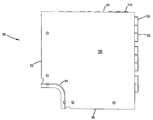
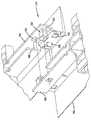
도 7 ~ 도 19 를 참조하면, 십자형 구성품 (18) 의 다른 특징이 도시되어 있다. 십자형 구성품 (18) 은 기부 (82), 네 개의 직립 측면 벽 (84), 및 네 개의 단부 (86) 를 포함한다. 단부는 커플러 (16) 에 연결될 수 있다. 기부 (82) 및 측면 벽 (84) 은 십자형 구성품 (18) 을 가로지르는 케이블 경로를 형성한다. 측면 벽 (84) 은 일 단부 (86) 로부터 인접한 단부 (86) 까지 십자형 구성품 (18) 내에서 구부러질 수도 있는 케이블을 위한 굴곡 반경 보호를 제공하기 위해 볼록하게 만곡된 형상을 갖는다. 단부 (86) 는 커플러 (16), 또는 십자형 구성품 (18) 에 잠기도록 구성된 다른 커플러에 장착될 수 있다.7-19, another feature of the
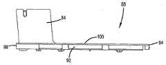
십자형 구성품 (18) 은 별개의 부품 또는 섹션 (88) 으로 조립되는 것이 바람직하다. 결합 장치 (90) 가 섹션 (88) 을 함께 연결시킨다. 각각의 섹션 (88) 은 가장자리 (92, 94, 96, 98), 기부 (100), 및 하나의 측면 벽 (84) 을 포함한다. 결합 장치 (90) 는 가장자리 (92) 를 인접한 섹션 (88) 의 가장자리 (94) 에 연결시킨다. 가장자리 (96, 98) 는 단부 (86) 를 형성한다. 도시된 실시예에서, 십자형 구성품 (18) 은 네 개의 동일한 섹션 (88) 으로 만들어진다. 이러한 구성의 한가지 장점은, 성형가능한 재료로 이루어진 구성품 (18) 을 만들기 위한 주형이 구성품 (18) 을 하나의 일체적인 부품으로 성형하는데 필요한 주형만큼 크지 않아도 된다는 것이다.The
결합 장치 (90) 는 가장자리 (92) 상의 숄더 (102), 및 가장자리 (94) 상의 가요성 탭 (110) 을 포함한다. 탭 (110) 은 숄더 (102) 와 맞물리는 가장자리 면 (112) 을 포함한다. 또한, 탭 (110) 은 탭 (110) 이 숄더 (102) 를 제거할 수 있게 하는 램프 (114) 를 포함함으로, 가장자리면 (112) 은 숄더 (102) 와 맞물릴 수 있다. 바람직하게는, 복수의 결합 숄더 (102) 및 탭 (110) 이 가장자리 (92, 94) 를 따라 각각 제공된다. u 형상의 돌출부 (116) 가 탭 (110) 을 둘러싼다. 결합할 때, 가장자리 (92) 상의 엔클로저 (enclosure) (104) 가 돌출부 (116) 를 둘러싼다. 하나의 섹션 (88) 을 다른 섹션 (88) 에 장착하기 위해, 가장자리 (94) 는 가장자리 (92) 위에 수직으로 위치된다. 탭 (110) 및 돌출부 (116) 는 가장자리 (112) 가 숄더 (102) 에 맞물릴 때까지 엔클로저 (104) 에 들어간다. 한가지 조립 방법에서, 두 개의 섹션이 함께 결합되고, 두 개의 다른 섹션이 함께 결합된 다음, 각각의 숄더 (102) 및 탭 (110) 이 두 개의 결합부 사이에서 결합되도록 두 개의 결합부를 회전시켜 두 개의 결합부를 함께 결합시킨다.The
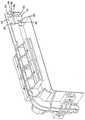
도 20 ~ 도 24 를 참조하면, T형상 구성품 (20) 은 상기와 같은 두 개의 섹션 (88), 및 종방향 섹션 (150) 으로 형성된다. 섹션 (88) 은 상기와 같이 함께 스냅결합한다. 섹션 (88) 은 상기와 같은 유형의 가장자리부 (192) 를 따라 있는 가용성 탭 (110) 및 가장자리부 (194) 를 따라 있는 숄더 (102) 를 포함하는 결합 장치 (152) 에 의해 종방향 섹션 (150) 에 스냅결합된다. 숄더 (102) 및 탭 (110) 이 결합되도록 결합된 섹션 (88) 은 종방향 섹션 (150) 에 대해 회전된다. 이러한 구성에 의해, 섹션 (88) 은 십자형 구성품 (18) 또는 T자형 구성품 (20) 을 조립하기 위해 사용될 수 있다. T자형 구성품 (20) 은 세 개의 단부로서, 상기 유형의 단부 (86), 및 상호 반대편에 있는 단부 (154) 를 구비하며, 이 모든 단부는 커플러 (16), 또는 T자형 구성품 (20) 에 잠기도록 구성되는 다른 커플러에 장착될 수 있다.20-24, the T-shaped
도 25 ~ 도 27 을 참조하면, L자형 구성품 (22) 이 더 상세하게 도시되어 있다. L자형 구성품 (22) 은 기부 (200) 와, 직립한 내측 벽 (202) 및 외측 벽 (204) 을 포함한다. 가장자리 (212, 214) 는 커플러 (16) 에 연결된다. 가장자리 (212, 214) 는 예컨대 약 45°의 각도로 서로 각을 이루고 있다. 이러한 구성은 각각의 단부에 연결된 구성품 사이에서의 케이블 경로의 방향의 변경을 가능게 한다. 두 개가 90°엘보로 사용될 수 있다. 상기 실시예에 있어서, 만곡된 안내 벽 또는 핀 (206, 208, 210) 이 엘보의 내부에 위치되어, 케이블을 안내하고 케이블이 내측 벽 (22) 에 모이지 않게 한다.25-27, the L-shaped
도 28 을 참조하면, 측방 트로프 섹션 경로 폭이 일 치수 (W1) 로부터 더 작은 치수 (W2) 로 감소하고 있는 축소부 구성품 (24) 이 도시되어 있다. 단부 (220) 는 24 인치와 같은 더 넓은 치수 (W1) 를 가지며, 반대편 단부 (222) 는 12 인치와 같은 더 좁은 치수 (W2) 를 갖는다. 축소부 구성품 (24) 은 커플러 (16), 또는 십자형 구성품 (18) 에 잠기도록 구성되는 다른 커플러에 장착될 수 있다.Referring to FIG. 28, there is shown a
도 29 를 참조하면, 안내 탭 (262) 이 돌출부 (64) 로부터 돌출해 있는 커플러 (260) 의 대안적인 실시예가 도시되어 있다. 안내 탭 (262) 은 시스템의 조립 동안 종방향 트로프 부재 (14) 의 포켓에 돌출부 (62) 가 위치되는 것을 돕는다.Referring to FIG. 29, an alternative embodiment of
도 30 ~ 도 34 를 참조하면, 커플러 (360) 의 대안적인 실시예가 도시되어 있다. 커플러 (360) 는 바람직하게 동일한 두 개의 섹션 (362, 364) 으로 구성되어 있다. 결합 장치 (370) 가 두 개의 섹션 (362, 364) 을 함께 장착시킨다. 결합 장치 (370) 의 한가지 바람직한 실시예는 스냅을 포함한다. 각각의 섹션 (362, 364) 은 서로 오프셋되어 있는 제 1 및 제 2 벽 (372, 374) 을 포함한다. 제 1 벽 (372) 은 숄더 (382) 를 구비한 제 1 탭 (380), 및 구멍 (384) 을 포함한다. 제 2 벽 (374) 은 숄더 (392) 를 구비한 제 2 탭 (390), 및 구멍 (394) 을 포함한다. 각각의 벽 (372) 의 제 1 탭 (380) 은 다른 섹션의 다른 벽 (372) 의 구멍 (384) 에 끼워진다. 각각의 벽 (374) 의 제 2 탭 (390) 은 다른 섹션의 다른 벽 (374) 의 구멍 (394) 에 끼워진다. 또한, 섹션을 함께 장착시킬 때, 절삭부 (396, 398) 또한 함께 결합될 수 있다. 커플러를 두 섹션으로 만들기 때문에, 성형가능한 재료로 커플링 (360) 을 만드는데 비용이 더 적게 드는 주형이 필요하다.30-34, an alternative embodiment of
상기 설명, 실시예 및 데이터는 본 발명의 제조 및 용도에 대한 완전한 설명을 제공한다. 본 발명의 많은 실시예는 본 발명의 사상 및 범위 내에서 이루어질 수 있기 때문에, 본 발명은 이하에 첨부된 청구항에 존재한다.The above description, examples and data provide a complete description of the manufacture and use of the invention. Since many embodiments of the invention can be made within the spirit and scope of the invention, the invention resides in the claims hereinafter appended.
Claims (12)
Translated fromKoreanApplications Claiming Priority (3)
| Application Number | Priority Date | Filing Date | Title |
|---|---|---|---|
| US11/246,003 | 2005-10-07 | ||
| US11/246,003US7471868B2 (en) | 2005-10-07 | 2005-10-07 | Cable trough system and method |
| PCT/US2006/038648WO2007044338A1 (en) | 2005-10-07 | 2006-09-29 | Cable trough system |
Publications (2)
| Publication Number | Publication Date |
|---|---|
| KR20080063497A KR20080063497A (en) | 2008-07-04 |
| KR101280647B1true KR101280647B1 (en) | 2013-07-01 |
Family
ID=37631254
Family Applications (1)
| Application Number | Title | Priority Date | Filing Date |
|---|---|---|---|
| KR1020087011017AExpired - Fee RelatedKR101280647B1 (en) | 2005-10-07 | 2006-09-29 | Cable trough system |
Country Status (8)
| Country | Link |
|---|---|
| US (5) | US7471868B2 (en) |
| EP (1) | EP1932225A1 (en) |
| KR (1) | KR101280647B1 (en) |
| CN (2) | CN101283494B (en) |
| AU (2) | AU2006302511B2 (en) |
| BR (1) | BRPI0616988A2 (en) |
| CA (1) | CA2620871C (en) |
| WO (1) | WO2007044338A1 (en) |
Families Citing this family (64)
| Publication number | Priority date | Publication date | Assignee | Title |
|---|---|---|---|---|
| US6631875B1 (en)* | 2000-09-26 | 2003-10-14 | Adc Telecommunications, Inc. | Cable trough with separate side elements |
| US7471868B2 (en) | 2005-10-07 | 2008-12-30 | Adc Telecommunications, Inc. | Cable trough system and method |
| US8070112B2 (en)* | 2007-01-19 | 2011-12-06 | Adc Telecommunications, Inc. | Lateral storage spool for overhead cable pathway |
| USD577684S1 (en) | 2007-01-26 | 2008-09-30 | Adc Telecommunications, Inc. | Fiber trough snaps |
| USD576108S1 (en) | 2007-01-26 | 2008-09-02 | Adc Telecommunications, Inc. | Fiber trough horizontal T component |
| USD576107S1 (en) | 2007-01-26 | 2008-09-02 | Adc Telecommunications, Inc. | Fiber trough lateral component |
| USD576559S1 (en) | 2007-01-26 | 2008-09-09 | Adc Telecommunications, Inc. | Fiber trough horizontal T component |
| USD576106S1 (en) | 2007-01-26 | 2008-09-02 | Adc Telecommunications, Inc. | Fiber trough lateral component |
| USD576109S1 (en) | 2007-01-26 | 2008-09-02 | Adc Telecommunications, Inc. | Fiber trough base |
| USD576560S1 (en) | 2007-01-26 | 2008-09-09 | Adc Telecommunications, Inc. | Fiber trough horizontal T component |
| US7742675B2 (en)* | 2007-01-26 | 2010-06-22 | Adc Telecommunications, Inc. | Cable trough system and method |
| USD576956S1 (en) | 2007-01-26 | 2008-09-16 | Adc Telecommunications, Inc. | Fiber trough base |
| US8452148B2 (en) | 2008-08-29 | 2013-05-28 | Corning Cable Systems Llc | Independently translatable modules and fiber optic equipment trays in fiber optic equipment |
| US11294136B2 (en) | 2008-08-29 | 2022-04-05 | Corning Optical Communications LLC | High density and bandwidth fiber optic apparatuses and related equipment and methods |
| US7627224B1 (en)* | 2008-12-24 | 2009-12-01 | At&T Intellectual Property I, L.P. | Cabinet fiber manager |
| GB0901544D0 (en)* | 2009-01-30 | 2009-03-11 | Trojan Services Ltd | A combined cable trough and walkway |
| EP2221932B1 (en) | 2009-02-24 | 2011-11-16 | CCS Technology Inc. | Holding device for a cable or an assembly for use with a cable |
| US20100220967A1 (en)* | 2009-02-27 | 2010-09-02 | Cooke Terry L | Hinged Fiber Optic Module Housing and Module |
| DE102009017319A1 (en)* | 2009-04-16 | 2010-10-21 | Airbus Deutschland Gmbh | Cable management device for an electrical wiring harness laid in an aircraft cabin |
| US8699838B2 (en) | 2009-05-14 | 2014-04-15 | Ccs Technology, Inc. | Fiber optic furcation module |
| US8538226B2 (en) | 2009-05-21 | 2013-09-17 | Corning Cable Systems Llc | Fiber optic equipment guides and rails configured with stopping position(s), and related equipment and methods |
| US9075216B2 (en) | 2009-05-21 | 2015-07-07 | Corning Cable Systems Llc | Fiber optic housings configured to accommodate fiber optic modules/cassettes and fiber optic panels, and related components and methods |
| EP2443497B1 (en) | 2009-06-19 | 2020-03-04 | Corning Cable Systems LLC | High density and bandwidth fiber optic apparatus |
| US8712206B2 (en) | 2009-06-19 | 2014-04-29 | Corning Cable Systems Llc | High-density fiber optic modules and module housings and related equipment |
| NL1037529C2 (en)* | 2009-12-04 | 2011-06-07 | Arend Jan Vliet | SYSTEM FOR THE REALIZATION OF A CABLE TRAY AND DIVIDING WALLS, COUPLING PLATES AND CLIPS AS PART OF THIS SYSTEM. |
| US8625950B2 (en) | 2009-12-18 | 2014-01-07 | Corning Cable Systems Llc | Rotary locking apparatus for fiber optic equipment trays and related methods |
| US8992099B2 (en) | 2010-02-04 | 2015-03-31 | Corning Cable Systems Llc | Optical interface cards, assemblies, and related methods, suited for installation and use in antenna system equipment |
| US8913866B2 (en) | 2010-03-26 | 2014-12-16 | Corning Cable Systems Llc | Movable adapter panel |
| CA2796221C (en) | 2010-04-16 | 2018-02-13 | Ccs Technology, Inc. | Sealing and strain relief device for data cables |
| EP2381284B1 (en) | 2010-04-23 | 2014-12-31 | CCS Technology Inc. | Under floor fiber optic distribution device |
| US9632270B2 (en)* | 2010-04-30 | 2017-04-25 | Corning Optical Communications LLC | Fiber optic housings configured for tool-less assembly, and related components and methods |
| US9720195B2 (en) | 2010-04-30 | 2017-08-01 | Corning Optical Communications LLC | Apparatuses and related components and methods for attachment and release of fiber optic housings to and from an equipment rack |
| US8705926B2 (en) | 2010-04-30 | 2014-04-22 | Corning Optical Communications LLC | Fiber optic housings having a removable top, and related components and methods |
| US8660397B2 (en) | 2010-04-30 | 2014-02-25 | Corning Cable Systems Llc | Multi-layer module |
| US9075217B2 (en) | 2010-04-30 | 2015-07-07 | Corning Cable Systems Llc | Apparatuses and related components and methods for expanding capacity of fiber optic housings |
| US8879881B2 (en) | 2010-04-30 | 2014-11-04 | Corning Cable Systems Llc | Rotatable routing guide and assembly |
| US9519118B2 (en) | 2010-04-30 | 2016-12-13 | Corning Optical Communications LLC | Removable fiber management sections for fiber optic housings, and related components and methods |
| US8718436B2 (en) | 2010-08-30 | 2014-05-06 | Corning Cable Systems Llc | Methods, apparatuses for providing secure fiber optic connections |
| US9279951B2 (en) | 2010-10-27 | 2016-03-08 | Corning Cable Systems Llc | Fiber optic module for limited space applications having a partially sealed module sub-assembly |
| US9116324B2 (en) | 2010-10-29 | 2015-08-25 | Corning Cable Systems Llc | Stacked fiber optic modules and fiber optic equipment configured to support stacked fiber optic modules |
| US8662760B2 (en) | 2010-10-29 | 2014-03-04 | Corning Cable Systems Llc | Fiber optic connector employing optical fiber guide member |
| CA2819235C (en) | 2010-11-30 | 2018-01-16 | Corning Cable Systems Llc | Fiber device holder and strain relief device |
| WO2012106510A2 (en) | 2011-02-02 | 2012-08-09 | Corning Cable Systems Llc | Dense fiber optic connector assemblies and related connectors and cables suitable for establishing optical connections for optical backplanes in equipment racks |
| US9008485B2 (en) | 2011-05-09 | 2015-04-14 | Corning Cable Systems Llc | Attachment mechanisms employed to attach a rear housing section to a fiber optic housing, and related assemblies and methods |
| AU2012275598A1 (en) | 2011-06-30 | 2014-01-16 | Corning Optical Communications LLC | Fiber optic equipment assemblies employing non-U-width-sized housings and related methods |
| US8953924B2 (en) | 2011-09-02 | 2015-02-10 | Corning Cable Systems Llc | Removable strain relief brackets for securing fiber optic cables and/or optical fibers to fiber optic equipment, and related assemblies and methods |
| US9038832B2 (en) | 2011-11-30 | 2015-05-26 | Corning Cable Systems Llc | Adapter panel support assembly |
| US8785779B1 (en)* | 2012-02-06 | 2014-07-22 | The Boeing Company | Snap-in raceway |
| US9250409B2 (en) | 2012-07-02 | 2016-02-02 | Corning Cable Systems Llc | Fiber-optic-module trays and drawers for fiber-optic equipment |
| US9042702B2 (en) | 2012-09-18 | 2015-05-26 | Corning Cable Systems Llc | Platforms and systems for fiber optic cable attachment |
| ES2551077T3 (en) | 2012-10-26 | 2015-11-16 | Ccs Technology, Inc. | Fiber optic management unit and fiber optic distribution device |
| TW201434225A (en)* | 2013-02-27 | 2014-09-01 | wen-zhong Zhuang | Easily assembled grooves set |
| US8985862B2 (en) | 2013-02-28 | 2015-03-24 | Corning Cable Systems Llc | High-density multi-fiber adapter housings |
| DE202014103562U1 (en)* | 2014-07-31 | 2014-09-11 | Igus Gmbh | guide means |
| WO2018081415A1 (en) | 2016-10-27 | 2018-05-03 | Steelcase Inc. | Flip top table |
| USD887992S1 (en) | 2018-04-25 | 2020-06-23 | Telect, Inc. | Cable trough attachment assembly |
| US20190331260A1 (en)* | 2018-04-25 | 2019-10-31 | Telect, Inc. | Cable Trough System |
| USD868004S1 (en) | 2018-04-25 | 2019-11-26 | Telect, Inc. | Cable trough lip |
| CN110429535A (en)* | 2019-08-20 | 2019-11-08 | 福建省顺安建筑工程有限公司 | Cabling decorative groove for building and its assembly method |
| US11646556B2 (en) | 2019-10-17 | 2023-05-09 | Panduit Corp. | Raceway system |
| BR102020005429A2 (en)* | 2020-03-18 | 2021-09-28 | Flávio Albertini Diaferia | IMPROVEMENTS IN SET OF MODULAR BEDS FOR STRUCTURED FIBER OPTIC WIRING |
| DE102020119796A1 (en) | 2020-07-28 | 2022-02-03 | Frank Beteiligungsgesellschaft Mbh | cable tray element |
| US11784475B2 (en) | 2021-01-12 | 2023-10-10 | Panduit Corp. | Intersection system for overhead cable trays |
| WO2024039695A1 (en)* | 2022-08-16 | 2024-02-22 | Ppc Broadband, Inc. | Modular and scalable optical fiber cable fixation, entry, storage, and splicing system providing expandability on demand |
Citations (4)
| Publication number | Priority date | Publication date | Assignee | Title |
|---|---|---|---|---|
| JPH06284544A (en)* | 1993-03-31 | 1994-10-07 | Idemitsu Petrochem Co Ltd | Trough made of synthetic resin |
| KR19980064789U (en)* | 1997-04-30 | 1998-11-25 | 윤정 | Cable trough |
| KR200173081Y1 (en) | 1999-09-20 | 2000-03-15 | 전안수 | Cable trough |
| KR20030007170A (en)* | 2001-07-13 | 2003-01-23 | 엔.티.티. 어드밴스 테크놀로지 가부시키가이샤 | Optical fiber coupler receptacle member |
Family Cites Families (73)
| Publication number | Priority date | Publication date | Assignee | Title |
|---|---|---|---|---|
| US799320A (en) | 1904-02-09 | 1905-09-12 | Orrin G Franks | Metal column, girder, and beam. |
| DE1130492B (en) | 1959-07-28 | 1962-05-30 | Ursus Kunststoff G M B H | Conduit |
| US3035800A (en) | 1959-11-24 | 1962-05-22 | Burndy Corp | Cable tray accessories |
| US3351699A (en) | 1965-03-19 | 1967-11-07 | Danzer Metal Works Co | Raceway for electrical cables and wires adapted to retain rf energy |
| US3761603A (en) | 1972-11-14 | 1973-09-25 | Amp Inc | Wiring raceway |
| DE2336132A1 (en)* | 1973-07-16 | 1975-02-06 | Siemens Ag | DEVICE FOR PHASE CONTROL |
| DE2337628A1 (en) | 1973-07-24 | 1975-02-06 | Intermercury Finance & Trad | INSTALLATION CHANNEL |
| US4077434A (en) | 1976-05-27 | 1978-03-07 | Federal Cartridge Corporation | Sealed lay-in conduit duct |
| US4234760A (en)* | 1978-12-18 | 1980-11-18 | Amp Incorporated | Covering for T-tap terminals |
| SU1272387A1 (en) | 1979-03-11 | 1986-11-23 | Государственный Проектный Институт "Электропроект" | Collapsible duct for laying wires and cables |
| USD278229S (en) | 1982-12-17 | 1985-04-02 | Jan Widell | Collector rail |
| DE3742448A1 (en) | 1987-12-15 | 1989-06-29 | Philips Patentverwaltung | Cable duct |
| JPH0419938Y2 (en) | 1987-12-17 | 1992-05-07 | ||
| US4907767A (en) | 1988-08-12 | 1990-03-13 | Hubbell Incorporated | Stackable modular duct assemblies |
| USD321682S (en) | 1989-07-31 | 1991-11-19 | Roy Henneberger | Guiding through, 90 degree down elbow for optical fibers |
| USD321862S (en) | 1989-07-31 | 1991-11-26 | Roy Henneberger | Guiding trough, horizontal T for optical fibers |
| USD320782S (en) | 1989-07-31 | 1991-10-15 | Roy Henneberger | Guiding trough downspout for optical fibers |
| US5316243A (en) | 1989-07-31 | 1994-05-31 | Adc Telecommunications, Inc. | Optic cable management |
| US5067678A (en) | 1989-07-31 | 1991-11-26 | Adc Telecommunications, Inc. | Optic cable management system |
| USD322596S (en) | 1989-07-31 | 1991-12-24 | Roy Henneberger | Guiding trough for optical fibers |
| USD320976S (en) | 1989-07-31 | 1991-10-22 | Roy Henneberger | Guiding trough, straight reducing adapter for optical fibers |
| US5160811A (en) | 1990-04-27 | 1992-11-03 | Tyton Corporation | Duct transition converter and flexible connectors including same |
| US5161580A (en) | 1990-08-27 | 1992-11-10 | Tyton Corporation | Cable duct fitting with removable cover |
| US5271585A (en) | 1990-10-01 | 1993-12-21 | Zetena Jr Maurice F | Modular fiber optics raceway permitting flexible installation |
| JPH05172281A (en) | 1991-12-25 | 1993-07-09 | Ee O Y Syst Kenkyusho:Kk | Duct assembling method and seam joint structure of duct |
| US5240209A (en) | 1992-11-17 | 1993-08-31 | Telect, Inc. | Telecommunication multiple cable carrier |
| US5335349A (en) | 1992-12-14 | 1994-08-02 | Telect, Inc. | Telecommunication overhead cable distribution assembly |
| US5469893A (en) | 1993-12-21 | 1995-11-28 | Panduit Corp. | Tab and slot fiber optic fitting |
| US5503354A (en) | 1994-01-04 | 1996-04-02 | Telect, Inc. | Telecommunication overhead cable distribution universal support bracket |
| CN2183625Y (en)* | 1994-01-21 | 1994-11-23 | 曹荣 | Split full-insulation power transmission bustar channel device |
| US5715099A (en) | 1994-04-28 | 1998-02-03 | Ricoh Company, Ltd. | Mounting method and structure for a solid-state image pickup element in an image reading-out apparatus |
| US6037543A (en) | 1994-11-17 | 2000-03-14 | Panduit Corp. | Wiring duct fittings |
| US5753855A (en) | 1994-11-17 | 1998-05-19 | Panduit Corp. | Wiring duct fittings |
| FR2735557B1 (en) | 1995-06-14 | 1997-08-14 | Seine Const Elec | FITTING FOR PROFILES |
| US5899025A (en) | 1996-03-22 | 1999-05-04 | Steelcase Inc. | Furniture system (pathways-spaceframe) |
| USD415471S (en) | 1998-07-22 | 1999-10-19 | Henry Stephen K | Modular cable protector |
| DE29610947U1 (en) | 1996-06-24 | 1996-08-22 | Miranda, Giovanni, 78549 Spaichingen | Cable duct profile |
| USD402262S (en) | 1996-12-06 | 1998-12-08 | Panduit Corp. | Straight dual raceway fitting |
| DE19709195C2 (en) | 1997-03-06 | 2001-09-06 | Ackermann Albert Gmbh Co | Electrical installation duct |
| US5752781A (en) | 1997-03-14 | 1998-05-19 | Adc Telecommunications, Inc. | Fiber trough coupling |
| US6037538A (en) | 1997-04-28 | 2000-03-14 | Brooks; Gary Douglas | Cable raceway |
| CN2307386Y (en)* | 1997-09-10 | 1999-02-10 | 南通金洋兴旺集团有限公司 | Corrosion-resisting steel cable bridge |
| US5923753A (en) | 1997-11-17 | 1999-07-13 | Adc Telecommunications, Inc. | Optic cable exit trough with bypass |
| US5937131A (en) | 1997-11-17 | 1999-08-10 | Adc Telecommunications, Inc. | Optical cable exit trough |
| US5995699A (en) | 1998-01-05 | 1999-11-30 | The Wiremold Company | Fiber optic cable raceway system cross reference to related applications |
| DE69800919T2 (en) | 1998-01-27 | 2002-04-04 | Placo S.R.L., Brugherio | Modular cable duct |
| USD413306S (en)* | 1998-06-04 | 1999-08-31 | Panduit Corp. | Right angle single raceway fitting |
| US6198047B1 (en) | 1999-02-08 | 2001-03-06 | Charles Barr | Cable tray with power channel |
| US6284975B1 (en)* | 1999-06-16 | 2001-09-04 | The Wiremold Company | Divider for raceway tee assembly |
| US6076779A (en) | 1999-08-04 | 2000-06-20 | Adc Telecommunications, Inc. | Cable guiding trough |
| US6739795B1 (en) | 2000-05-25 | 2004-05-25 | Adc Telecommunications, Inc. | Telescoping trough |
| US6450458B1 (en) | 2000-06-01 | 2002-09-17 | Panduit Corp. | Cable duct coupler with locking clip |
| US6523791B2 (en) | 2000-06-01 | 2003-02-25 | Panduit Corp. | Cable duct coupler |
| US6437244B1 (en) | 2000-06-05 | 2002-08-20 | Panduit Corp. | Wiring duct system hinge arrangement |
| US6631875B1 (en) | 2000-09-26 | 2003-10-14 | Adc Telecommunications, Inc. | Cable trough with separate side elements |
| US6535683B1 (en) | 2000-10-06 | 2003-03-18 | Adc Telecommunications, Inc. | Cable exit trough with cover |
| US6625373B1 (en) | 2000-10-06 | 2003-09-23 | Adc Telecommunications, Inc. | Cable exit trough with insert |
| US6522823B1 (en) | 2000-11-06 | 2003-02-18 | Adc Telecommunications, Inc. | Low profile cable exit trough |
| US6708918B2 (en) | 2001-03-01 | 2004-03-23 | Adc Telecommunications, Inc. | Cable guiding fins |
| JP3961234B2 (en)* | 2001-04-27 | 2007-08-22 | 矢崎総業株式会社 | Locking structure |
| FR2827434B1 (en) | 2001-07-13 | 2003-12-12 | Legrand Sa | ACCESSORY FOR CHANNEL WITH DIFFERENT HEIGHTS |
| US6810191B2 (en)* | 2001-07-20 | 2004-10-26 | Adc Telecommunications, Inc. | Cable trough cover |
| US6603073B2 (en) | 2001-09-12 | 2003-08-05 | Adc Telecommunications, Inc. | Snap together cable trough system |
| US6634805B1 (en) | 2001-10-10 | 2003-10-21 | Advanced Micro Devices, Inc. | Parallel plate development |
| US6559378B1 (en) | 2001-10-31 | 2003-05-06 | Panduit Corp. | Reducer fitting for routing system |
| US6709186B2 (en) | 2001-11-16 | 2004-03-23 | Adc Telecommunications, Inc. | Coupler for cable trough |
| US7093997B2 (en) | 2002-03-27 | 2006-08-22 | Adc Telecommunications, Inc. | Coupler for cable trough |
| MXPA04009279A (en)* | 2002-03-27 | 2005-01-25 | Adc Telecommunications Inc | Coupler for cable trough. |
| US7034227B2 (en) | 2002-08-19 | 2006-04-25 | Fox Ron W | Cable trough |
| US7045707B1 (en) | 2005-03-07 | 2006-05-16 | The Wiremold Company | Surface mounted perimeter raceway offset assembly |
| US7471868B2 (en) | 2005-10-07 | 2008-12-30 | Adc Telecommunications, Inc. | Cable trough system and method |
| US7742675B2 (en)* | 2007-01-26 | 2010-06-22 | Adc Telecommunications, Inc. | Cable trough system and method |
| US7896295B2 (en)* | 2007-02-21 | 2011-03-01 | Adc Telecommunications, Inc. | Coupler for cable trough |
- 2005
- 2005-10-07USUS11/246,003patent/US7471868B2/ennot_activeExpired - Lifetime
- 2006
- 2006-09-29EPEP06816134Apatent/EP1932225A1/ennot_activeWithdrawn
- 2006-09-29WOPCT/US2006/038648patent/WO2007044338A1/enactiveApplication Filing
- 2006-09-29AUAU2006302511Apatent/AU2006302511B2/ennot_activeCeased
- 2006-09-29CNCN2006800371005Apatent/CN101283494B/ennot_activeExpired - Fee Related
- 2006-09-29CACA2620871Apatent/CA2620871C/ennot_activeExpired - Fee Related
- 2006-09-29KRKR1020087011017Apatent/KR101280647B1/ennot_activeExpired - Fee Related
- 2006-09-29BRBRPI0616988-0Apatent/BRPI0616988A2/ennot_activeIP Right Cessation
- 2006-09-29CNCN2011100061425Apatent/CN102163825B/ennot_activeExpired - Fee Related
- 2008
- 2008-11-21USUS29/328,318patent/USD609192S1/ennot_activeExpired - Lifetime
- 2008-11-21USUS12/275,979patent/US7668433B2/ennot_activeExpired - Fee Related
- 2010
- 2010-02-15USUS12/705,849patent/US8965167B2/enactiveActive
- 2010-12-21AUAU2010257337Apatent/AU2010257337B2/ennot_activeCeased
- 2015
- 2015-01-21USUS14/601,581patent/US9356436B2/ennot_activeExpired - Lifetime
Patent Citations (4)
| Publication number | Priority date | Publication date | Assignee | Title |
|---|---|---|---|---|
| JPH06284544A (en)* | 1993-03-31 | 1994-10-07 | Idemitsu Petrochem Co Ltd | Trough made of synthetic resin |
| KR19980064789U (en)* | 1997-04-30 | 1998-11-25 | 윤정 | Cable trough |
| KR200173081Y1 (en) | 1999-09-20 | 2000-03-15 | 전안수 | Cable trough |
| KR20030007170A (en)* | 2001-07-13 | 2003-01-23 | 엔.티.티. 어드밴스 테크놀로지 가부시키가이샤 | Optical fiber coupler receptacle member |
Also Published As
| Publication number | Publication date |
|---|---|
| WO2007044338A1 (en) | 2007-04-19 |
| US9356436B2 (en) | 2016-05-31 |
| USD609192S1 (en) | 2010-02-02 |
| EP1932225A1 (en) | 2008-06-18 |
| US20070092196A1 (en) | 2007-04-26 |
| US7668433B2 (en) | 2010-02-23 |
| KR20080063497A (en) | 2008-07-04 |
| US8965167B2 (en) | 2015-02-24 |
| CA2620871A1 (en) | 2007-04-19 |
| AU2006302511B2 (en) | 2010-09-23 |
| CN101283494B (en) | 2011-02-23 |
| CA2620871C (en) | 2014-12-09 |
| CN101283494A (en) | 2008-10-08 |
| US7471868B2 (en) | 2008-12-30 |
| AU2010257337A1 (en) | 2011-01-20 |
| AU2006302511A1 (en) | 2007-04-19 |
| AU2010257337B2 (en) | 2015-03-12 |
| US20100142911A1 (en) | 2010-06-10 |
| CN102163825B (en) | 2013-03-06 |
| US20090158578A1 (en) | 2009-06-25 |
| US20150200526A1 (en) | 2015-07-16 |
| CN102163825A (en) | 2011-08-24 |
| BRPI0616988A2 (en) | 2011-07-05 |
Similar Documents
| Publication | Publication Date | Title |
|---|---|---|
| KR101280647B1 (en) | Cable trough system | |
| US6631875B1 (en) | Cable trough with separate side elements | |
| US8254744B2 (en) | Cable trough system and method | |
| CN101473501B (en) | Cable trough system and related accessories and connection method between trough system and accessories | |
| US6739795B1 (en) | Telescoping trough | |
| US20030015627A1 (en) | Flexible snap-together cable trough | |
| ZA200106241B (en) | Vertical cable management system with ribcage structure. | |
| US6470129B1 (en) | Modular cable management trough section | |
| HK1108300A (en) | Cable through with separate side elements |
Legal Events
| Date | Code | Title | Description |
|---|---|---|---|
| PA0105 | International application | St.27 status event code:A-0-1-A10-A15-nap-PA0105 | |
| PG1501 | Laying open of application | St.27 status event code:A-1-1-Q10-Q12-nap-PG1501 | |
| A201 | Request for examination | ||
| PA0201 | Request for examination | St.27 status event code:A-1-2-D10-D11-exm-PA0201 | |
| E902 | Notification of reason for refusal | ||
| PE0902 | Notice of grounds for rejection | St.27 status event code:A-1-2-D10-D21-exm-PE0902 | |
| T11-X000 | Administrative time limit extension requested | St.27 status event code:U-3-3-T10-T11-oth-X000 | |
| E13-X000 | Pre-grant limitation requested | St.27 status event code:A-2-3-E10-E13-lim-X000 | |
| P11-X000 | Amendment of application requested | St.27 status event code:A-2-2-P10-P11-nap-X000 | |
| P13-X000 | Application amended | St.27 status event code:A-2-2-P10-P13-nap-X000 | |
| E701 | Decision to grant or registration of patent right | ||
| PE0701 | Decision of registration | St.27 status event code:A-1-2-D10-D22-exm-PE0701 | |
| GRNT | Written decision to grant | ||
| PR0701 | Registration of establishment | St.27 status event code:A-2-4-F10-F11-exm-PR0701 | |
| PR1002 | Payment of registration fee | Fee payment year number:1 St.27 status event code:A-2-2-U10-U12-oth-PR1002 | |
| PG1601 | Publication of registration | St.27 status event code:A-4-4-Q10-Q13-nap-PG1601 | |
| R18-X000 | Changes to party contact information recorded | St.27 status event code:A-5-5-R10-R18-oth-X000 | |
| R18-X000 | Changes to party contact information recorded | St.27 status event code:A-5-5-R10-R18-oth-X000 | |
| R18-X000 | Changes to party contact information recorded | St.27 status event code:A-5-5-R10-R18-oth-X000 | |
| FPAY | Annual fee payment | Payment date:20160615 Year of fee payment:4 | |
| PR1001 | Payment of annual fee | Fee payment year number:4 St.27 status event code:A-4-4-U10-U11-oth-PR1001 | |
| PN2301 | Change of applicant | St.27 status event code:A-5-5-R10-R11-asn-PN2301 St.27 status event code:A-5-5-R10-R13-asn-PN2301 | |
| FPAY | Annual fee payment | Payment date:20170614 Year of fee payment:5 | |
| PR1001 | Payment of annual fee | Fee payment year number:5 St.27 status event code:A-4-4-U10-U11-oth-PR1001 | |
| LAPS | Lapse due to unpaid annual fee | ||
| PC1903 | Unpaid annual fee | Not in force date:20180626 Payment event data comment text:Termination Category : DEFAULT_OF_REGISTRATION_FEE St.27 status event code:A-4-4-U10-U13-oth-PC1903 | |
| PC1903 | Unpaid annual fee | Ip right cessation event data comment text:Termination Category : DEFAULT_OF_REGISTRATION_FEE Not in force date:20180626 St.27 status event code:N-4-6-H10-H13-oth-PC1903 | |
| R18-X000 | Changes to party contact information recorded | St.27 status event code:A-5-5-R10-R18-oth-X000 | |
| P22-X000 | Classification modified | St.27 status event code:A-4-4-P10-P22-nap-X000 |