KR101280520B1 - Power Generation System Using Waste Heat - Google Patents
Power Generation System Using Waste HeatDownload PDFInfo
- Publication number
- KR101280520B1 KR101280520B1KR1020110046584AKR20110046584AKR101280520B1KR 101280520 B1KR101280520 B1KR 101280520B1KR 1020110046584 AKR1020110046584 AKR 1020110046584AKR 20110046584 AKR20110046584 AKR 20110046584AKR 101280520 B1KR101280520 B1KR 101280520B1
- Authority
- KR
- South Korea
- Prior art keywords
- working fluid
- waste heat
- heat source
- evaporator
- condenser unit
- Prior art date
- Legal status (The legal status is an assumption and is not a legal conclusion. Google has not performed a legal analysis and makes no representation as to the accuracy of the status listed.)
- Expired - Fee Related
Links
Images


Classifications
- F—MECHANICAL ENGINEERING; LIGHTING; HEATING; WEAPONS; BLASTING
- F01—MACHINES OR ENGINES IN GENERAL; ENGINE PLANTS IN GENERAL; STEAM ENGINES
- F01K—STEAM ENGINE PLANTS; STEAM ACCUMULATORS; ENGINE PLANTS NOT OTHERWISE PROVIDED FOR; ENGINES USING SPECIAL WORKING FLUIDS OR CYCLES
- F01K23/00—Plants characterised by more than one engine delivering power external to the plant, the engines being driven by different fluids
- F01K23/02—Plants characterised by more than one engine delivering power external to the plant, the engines being driven by different fluids the engine cycles being thermally coupled
- F01K23/06—Plants characterised by more than one engine delivering power external to the plant, the engines being driven by different fluids the engine cycles being thermally coupled combustion heat from one cycle heating the fluid in another cycle
- F01K23/10—Plants characterised by more than one engine delivering power external to the plant, the engines being driven by different fluids the engine cycles being thermally coupled combustion heat from one cycle heating the fluid in another cycle with exhaust fluid of one cycle heating the fluid in another cycle
- F—MECHANICAL ENGINEERING; LIGHTING; HEATING; WEAPONS; BLASTING
- F01—MACHINES OR ENGINES IN GENERAL; ENGINE PLANTS IN GENERAL; STEAM ENGINES
- F01K—STEAM ENGINE PLANTS; STEAM ACCUMULATORS; ENGINE PLANTS NOT OTHERWISE PROVIDED FOR; ENGINES USING SPECIAL WORKING FLUIDS OR CYCLES
- F01K9/00—Plants characterised by condensers arranged or modified to co-operate with the engines
- F01K9/02—Arrangements or modifications of condensate or air pumps
- F—MECHANICAL ENGINEERING; LIGHTING; HEATING; WEAPONS; BLASTING
- F02—COMBUSTION ENGINES; HOT-GAS OR COMBUSTION-PRODUCT ENGINE PLANTS
- F02G—HOT GAS OR COMBUSTION-PRODUCT POSITIVE-DISPLACEMENT ENGINE PLANTS; USE OF WASTE HEAT OF COMBUSTION ENGINES; NOT OTHERWISE PROVIDED FOR
- F02G5/00—Profiting from waste heat of combustion engines, not otherwise provided for
- F02G5/02—Profiting from waste heat of exhaust gases
- Y—GENERAL TAGGING OF NEW TECHNOLOGICAL DEVELOPMENTS; GENERAL TAGGING OF CROSS-SECTIONAL TECHNOLOGIES SPANNING OVER SEVERAL SECTIONS OF THE IPC; TECHNICAL SUBJECTS COVERED BY FORMER USPC CROSS-REFERENCE ART COLLECTIONS [XRACs] AND DIGESTS
- Y02—TECHNOLOGIES OR APPLICATIONS FOR MITIGATION OR ADAPTATION AGAINST CLIMATE CHANGE
- Y02T—CLIMATE CHANGE MITIGATION TECHNOLOGIES RELATED TO TRANSPORTATION
- Y02T10/00—Road transport of goods or passengers
- Y02T10/10—Internal combustion engine [ICE] based vehicles
- Y02T10/12—Improving ICE efficiencies
Landscapes
- Engineering & Computer Science (AREA)
- Chemical & Material Sciences (AREA)
- Combustion & Propulsion (AREA)
- Mechanical Engineering (AREA)
- General Engineering & Computer Science (AREA)
- Engine Equipment That Uses Special Cycles (AREA)
Abstract
Translated fromKoreanDescription
Translated fromKorean본 발명은, 전력생산 시스템에 관한 것으로서, 보다 상세하게는, 선박의 폐열원을 이용하여 전력을 생산하는 폐열원 전력생산 시스템에 관한 것이다.BACKGROUND OF THE INVENTION 1. Field of the Invention The present invention relates to a power generation system, and more particularly, to a waste heat source power generation system for producing electric power using a waste heat source of a ship.
일반적으로 선박의 동력부는 170 내지 1000℃ 온도 범위의 배기가스 산유체를 생산할 수 있다. 일반적으로, 배기가스 산유체는 주위로 방출되고 열 에너지는 손실된다. 그러나, 이러한 배기가스로부터의 열 에너지는 랭킨 사이클(Rankine Cycle) 시스템을 구동하는 에너지원으로서 사용될 수 있다.In general, the power unit of the ship can produce the exhaust gas fluid in the temperature range of 170 to 1000 ℃. In general, exhaust gas fluid is released to the environment and heat energy is lost. However, the thermal energy from this exhaust can be used as an energy source to drive a Rankine Cycle system.
랭킨 사이클 시스템은 발전기에 결합된 터빈(Turbine)과, 콘덴서(Condenser)와, 펌프(Pump)와, 증발기(Vaporizer)를 포함할 수 있다. 증발기는 열원으로부터 에너지를 공급받는다. 열원으로부터의 에너지는 증발기를 통과하는 작동유체(Working Fluid)로 전달된다. 그 후에 에너지를 받은 작동유체는 터빈에 동력을 공급한다. 작동유체는 터빈을 벗어난 후, 콘덴서를 통과한 다음, 펌프에 의하여 증발기로 다시 펌핑된다.The Rankine cycle system may include a turbine coupled to a generator, a condenser, a pump, and a vaporizer. The evaporator is energized from a heat source. Energy from the heat source is transferred to the working fluid passing through the evaporator. The energized working fluid then powers the turbine. The working fluid leaves the turbine, passes through a condenser and is then pumped back to the evaporator by a pump.
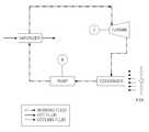
도 1 및 도 2는 랭킨 사이클 시스템의 개략적인 구성도이다.1 and 2 are schematic configuration diagrams of a Rankine cycle system.
도 1은 터빈을 통과한 작동유체의 냉각을 위하여 콘덴서에서 냉각수를 모터에 의하여 공급받아 작동유체를 냉각하는 수냉식 시스템을 나타내고, 도 2는 콘덴서에서 냉각 공기를 팬(fan)으로부터 유입받아 작동유체를 냉각시키는 공랭식 시스템을 나타낸다.FIG. 1 shows a water cooling system for cooling a working fluid by receiving cooling water from a condenser for cooling a working fluid passing through a turbine, and FIG. 2 shows a working fluid receiving cooling air from a fan in a condenser. An air cooled system for cooling is shown.
종래에는, 선박에서 폐열 회수를 위한 폐열원 전력생산 시스템으로 수냉식 시스템을 주로 사용하였으며, 냉각수로는 해수를 이용하였다. 따라서, 해수를 공급하는데 적은 동력을 소모하도록 선박의 하부나 내부에 랭킨 사이클을 배치하여 사용하고 있다.Conventionally, a water cooling system is mainly used as a waste heat source power generation system for waste heat recovery in a ship, and seawater is used as cooling water. Therefore, Rankine cycles are used in the lower part or inside of the ship so as to consume less power for supplying seawater.
그러나, 이러한 종래의 폐열원 전력생산 시스템에 있어서는, 냉각수를 공급하기 위한 소모 동력이 커서 폐열 회수를 통한 발전의 효과가 감소하고, 또한 공랭식 시스템을 적용하더라도 냉각 공기를 유입시키기 위한 팬을 구동하기 위한 동력이 사용되며 냉각 효율이 저조한 문제점이 있었다. 또한, 폐열원 전력생산 시스템을 선박의 내부에 설치하기 위한 공간의 협소성 문제도 제기되고 있는 실정이다.However, in such a conventional waste heat source power generation system, the power consumption for supplying the cooling water is large, so that the effect of power generation through waste heat recovery is reduced, and even for applying an air cooling system, There is a problem that power is used and cooling efficiency is low. In addition, the situation of the narrowness of space for installing the waste heat source power generation system inside the ship has also been raised.
본 발명의 실시예들은, 폐열원 전력생산 시스템의 콘덴서를 선박의 외부에 설치함으로써 폐열원 전력생산 시스템의 전력 생산 효율을 높이고, 선박 외부의 공간을 이용함으로써 설치 공간을 효율적으로 확보할 수 있는 폐열원 전력생산 시스템을 제공하고자 한다.Embodiments of the present invention, by installing the condenser of the waste heat source power production system to the outside of the vessel to increase the power production efficiency of the waste heat source power production system, by using the space outside the vessel waste heat that can efficiently secure the installation space To provide a raw power production system.
본 발명의 일 측면에 따르면, 선박의 폐열원으로부터 에너지를 공급받아 작동유체를 증발시키는 증발기; 상기 증발기와 연결되며 발전기와 결합된 터빈; 상기 터빈과 연결되며 상기 작동유체를 응축시키는 콘덴서 유닛; 및 상기 콘덴서 유닛과 연결되며 상기 작동유체를 상기 증발기로 공급하는 공급 펌프를 포함하며, 상기 콘덴서 유닛은, 상기 선박의 외부에 마련되어 공기 냉각에 의하여 상기 작동유체를 응축시키는 것을 특징으로 하는 폐열원 전력생산 시스템이 제공될 수 있다.According to an aspect of the invention, the evaporator for receiving the energy from the waste heat source of the vessel to evaporate the working fluid; A turbine connected to the evaporator and coupled to a generator; A condenser unit connected to the turbine and condensing the working fluid; And a supply pump connected to the condenser unit and supplying the working fluid to the evaporator, wherein the condenser unit is provided outside of the ship to condense the working fluid by air cooling. Production systems can be provided.
상기 콘덴서 유닛은, 상기 터빈을 통과한 상기 작동유체가 유입되는 유입 매니폴드; 상기 유입 매니폴드의 하방에 마련되어 상기 작동유체가 응축되어 저장되는 응축액탱크; 및 상기 유입 매니폴드와 상기 응축액탱크를 연결하도록 마련되며, 상기 작동유체를 냉각시키는 적어도 하나의 핀 튜브(tube)를 포함할 수 있다.The condenser unit may include an inflow manifold through which the working fluid passing through the turbine flows in; A condensate tank provided under the inlet manifold to condense and store the working fluid; And at least one fin tube provided to connect the inlet manifold and the condensate tank to cool the working fluid.
상기 핀 튜브는, 상기 핀 튜브의 외측면에 방사상으로 연장된 복수개의 냉각 핀(fin)을 포함할 수 있다.The fin tube may include a plurality of cooling fins extending radially on an outer surface of the fin tube.
상기 콘덴서 유닛은, 상기 핀 튜브의 전방에 마련되어 선박 공조시스템(AHU)의 가습기로부터 드레인(drain)되는 유체를 분무하는 냉각수 공급 유닛을 더 포함할 수 있다.The condenser unit may further include a cooling water supply unit provided in front of the fin tube to spray fluid drained from the humidifier of the vessel air conditioning system AHU.
상기 냉각수 공급 유닛은, 상기 선박 공조시스템의 가습기로부터 드레인되는 유체를 공급하는 공급부; 및 상기 핀 튜브의 전방에 마련되어 상기 공급부로부터 공급된 유체를 분무하는 분무부를 포함할 수 있다.The cooling water supply unit, the supply unit for supplying a fluid drained from the humidifier of the ship air conditioning system; And a spraying unit provided in front of the fin tube to spray the fluid supplied from the supplying unit.
상기 증발기, 상기 터빈, 상기 공급 펌프는 하나의 모듈로 마련될 수 있다.The evaporator, the turbine, and the feed pump may be provided as one module.
상기 폐열원 전력생산 시스템은, 상기 선박의 엔진 배기가스가 배출되는 펀넬(funnel)의 상부에 마련되어 상기 증발기로 열 에너지를 전달하는 열교환기를 더 포함할 수 있다.The waste heat source power generation system may further include a heat exchanger provided at an upper portion of a funnel through which the engine exhaust gas of the vessel is discharged to transfer thermal energy to the evaporator.
상기 증발기, 상기 터빈, 상기 공급 펌프는 상기 열교환기와 인접하여 펀넬 케이싱(funnel casing)의 내부에 마련될 수 있다.The evaporator, the turbine and the feed pump may be provided inside the funnel casing adjacent to the heat exchanger.
상기 콘덴서 유닛은 펀넬 케이싱(funnel casing)의 양쪽 외측부에 한 쌍이 배치될 수 있다.The condenser unit may be disposed in pairs on both outer sides of the funnel casing.
상기 콘덴서 유닛은,상기 터빈을 통과한 상기 작동유체가 유입되는 유입 매니폴드; 상기 유입 매니폴드의 하방에 마련되어 상기 작동유체가 응축되어 저장되는 응축액탱크; 상기 유입 매니폴드와 상기 응축액탱크를 연결하도록 마련되며, 상기 작동유체를 냉각시키는 적어도 하나의 핀 튜브(fin-tube); 및 상기 핀 튜브의 전방에 마련되어 선박 공조시스템(AHU)의 가습기로부터 드레인(drain)되는 유체를 분무하는 냉각수 공급 유닛을 포함할 수 있다.The condenser unit includes: an inflow manifold through which the working fluid passing through the turbine flows in; A condensate tank provided under the inlet manifold to condense and store the working fluid; At least one fin tube provided to connect the inlet manifold and the condensate tank to cool the working fluid; And a cooling water supply unit provided at the front of the fin tube to spray fluid drained from the humidifier of the vessel air conditioning system (AHU).
상기 콘덴서 유닛은, 선박에 적재된 적재화물보다 높은 위치에 마련될 수 있다.The condenser unit may be provided at a position higher than a load loaded on a ship.
본 발명의 실시예들은, 폐열원 전력생산 시스템의 콘덴서를 선박의 외부에 설치함으로써 폐열원 전력생산 시스템의 전력 생산 효율을 높이고, 선박 외부의 공간을 이용함으로써 설치 공간을 효율적으로 확보할 수 있는 폐열원 전력생산 시스템이 제공된다.Embodiments of the present invention, by installing the condenser of the waste heat source power production system to the outside of the vessel to increase the power production efficiency of the waste heat source power production system, by using the space outside the vessel waste heat that can efficiently secure the installation space A raw power generation system is provided.
도 1은 수냉식 랭킨 사이클 시스템의 개략적인 구성도이다.
도 2는 공랭식 랭킨 사이클 시스템의 개략적인 구성도이다.
도 3은 본 발명의 일 실시예에 따른 폐열원 전력생산 시스템의 개략적인 구성도이다.
도 4는 도 3의 주요부 확대도이다.
도 5는 본 발명의 다른 실시예에 따른 폐열원 전력생산 시스템의 개략적인 구성도이다.
도 6은 도 5의 측면도이다.
도 7은 도 5의 폐열원 전력생산 시스템의 변형 실시예를 나타낸 구성도이다.1 is a schematic diagram of a water-cooled Rankine cycle system.
2 is a schematic diagram of an air-cooled Rankine cycle system.
3 is a schematic configuration diagram of a waste heat source power production system according to an embodiment of the present invention.
4 is an enlarged view of the main part of Fig.
5 is a schematic configuration diagram of a waste heat source power production system according to another embodiment of the present invention.
Fig. 6 is a side view of Fig. 5. Fig.
7 is a configuration diagram showing a modified embodiment of the waste heat source power production system of FIG.
본 발명과 본 발명의 동작상의 이점 및 본 발명의 실시에 의하여 달성되는 목적을 충분히 이해하기 위해서는 본 발명의 바람직한 실시 예를 예시하는 첨부 도면 및 첨부 도면에 기재된 내용을 참조하여야만 한다.In order to fully understand the present invention, operational advantages of the present invention, and objects achieved by the practice of the present invention, reference should be made to the accompanying drawings and the accompanying drawings which illustrate preferred embodiments of the present invention.
이하, 첨부된 도면을 참조하여 본 발명의 바람직한 실시 예를 설명함으로써, 본 발명을 상세히 설명한다. 각 도면에 제시된 동일한 참조부호는 동일한 부재를 나타낸다.Hereinafter, the present invention will be described in detail with reference to the preferred embodiments of the present invention with reference to the accompanying drawings. Like reference symbols in the drawings denote like elements.
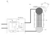
도 3은 본 발명의 일 실시예에 따른 폐열원 전력생산 시스템의 개략적인 구성도이고, 도 4는 도 3의 주요부 확대도이다.3 is a schematic configuration diagram of a waste heat source power generation system according to an embodiment of the present invention, and FIG. 4 is an enlarged view of a main part of FIG. 3.
이들 도면에 도시된 바와 같이, 본 발명의 일 실시예에 따른 폐열원 전력생산 시스템(100)은, 선박(10)의 폐열원으로부터 에너지를 공급받아 작동유체(Working Fluid)를 증발시키는 증발기(110, Vaporizer)와, 증발기(110)와 연결되며 발전기(121, Generator)와 결합된 터빈(120, Turbine)과, 터빈(120)과 연결되며 작동유체를 응축시키는 콘덴서 유닛(130, Condenser Unit)과, 콘덴서 유닛(130)과 연결되며 작동유체를 증발기(110)로 공급하는 공급 펌프(140, Pump)를 포함한다.As shown in these figures, the waste heat source
먼저, 선박(10)의 폐열원은, 선박(10)의 동력 기관에서 선박(10)을 추진시키는 동력을 발생시키고 난 후의 에너지원을 말하며, 대표적인 것으로는 추진용 엔진(11)에서 나오는 배기가스가 있다. 또한, 과급기의 압축공기, 자켓(Jacket)의 냉각수, 윤활유의 냉각수와 같이 높은 엔탈피(enthalpy)를 가지고 있는 다양한 열원들이 사용될 수도 있다.First, the waste heat source of the
본 실시예에서는, 엔진(11, 도5 참조)의 배기가스가 증발기(110)에 에너지를 공급하여 증발기(110)를 통과하는 작동유체를 증발시킨다. 증발기(110)에서 고온 고압으로 형성된 작동유체는 터빈(120)으로 이동된다.In this embodiment, the exhaust gas of the engine 11 (refer to FIG. 5) supplies energy to the
터빈(120)은, 증발기(110)로부터 이동된 고온 고압의 작동유체에 의하여 작동하게 되고 이와 결합되어 있는 발전기(121)에 의해 전력이 생산된다.The
콘덴서 유닛(130)은, 터빈(120)을 거친 작동유체를 냉각시킨다. 랭킨 사이클에서의 발전 효율은 콘덴서 유닛(130)에서의 냉각 효율이 높을수록, 이와 비례하여 증가하기 때문에 콘덴서 유닛(130)에서의 냉각 효율을 증가시키는 것이 전체 시스템의 전력 생산 효율을 증가시킬 수 있는 방법이 된다.The
콘덴서 유닛(130)은, 선박(10)의 실외에 마련되어 공기 냉각에 의하여 작동유체를 냉각시킨다. 선박(10)의 기관실에 존재하는 다양한 폐열원은 선박(10)의 엔진(11)이 동작함에 따라 발생하는 것이므로 폐열 회수 시스템도 선박(10)의 운항을 전제로 작동되는 것임을 고려할 때, 콘덴서 유닛(130)을 선박(10)의 외부에 마련하는 경우 선박(10)의 운항에 따라 선상에 공기의 유동이 발생하므로 공기의 강제 유동을 위한 냉각 팬(fan) 없이도 자연적인 공기 냉각 효과를 달성할 수 있게 된다.The
이를 위하여 콘덴서 유닛(130)은, 도 4를 참조하면, 터빈(120)을 통과한 작동유체가 유입되는 유입 매니폴드(131)와, 유입 매니폴드(131)의 하방에 마련되어 작동유체가 응축되어 저장되는 응축액탱크(132)와, 유입 매니폴드(131)와 응축액탱크(132)를 연결하도록 마련되며 작동유체를 냉각시키는 적어도 하나의 핀 튜브(133, fin-tube)를 포함한다.For this purpose, referring to FIG. 4, the
유입 매니폴드(131)는 터빈(120)을 작동시키고난 후의 작동유체가 유입되는 부분이며 작동유체는 터빈(120)을 작동시킨 후에도 고온의 상태이므로 유입 매니폴드(131) 하부에 마련되는 핀 튜브(133)를 통과하여 작동유체를 응축액탱크(132)로 이동시키면서 선상에 발생되는 공기 유동에 의하여 작동유체를 냉각시킨다.The
핀 튜브(133)는, 유입 매니폴드(131)와 응축액탱크(132)를 연결하여 작동유체가 흐를 수 있도록 마련되는 관 형상의 이동 통로로서 외부에는 접촉면적을 증대시켜서 공기 냉각의 효율성을 높여주는 다수의 냉각 핀(fin)이 마련된다. 핀 튜브(133)는 작동유체의 이동량에 맞추어 복수개가 마련된다.The
또한, 콘덴서 유닛(130)은, 냉각효율을 증대시키기 위하여 핀 튜브(133)의 전방에 마련되어 선박(10) 공조시스템(Air Handling Unit, AHU)의 가습기로부터 드레인(drain)되는 유체를 분무하는 냉각수 공급 유닛(134)을 더 포함한다.In addition, the
선박(10) 공조시스템은, 선실 내부의 온도와 습도를 쾌적하기 유지시켜 주기 위하여 사용되는 공기 조화 시스템을 말하며, 선실 내부에 일정한 습도를 유지시켜주기 위하여 기화식 또는 무화식의 가습 방법을 사용한다. 두 방식 모두 유체를 통과시키면서 선실 내부의 습도를 유지시키는 방식이며, 이에 의해서 하루에 드레인(drain)되는 유체의 양은 대략 5~50톤(ton) 정도이며 드레인되는 유체의 온도는 10℃ 정도이다. 일반적인 ISO 기준의 외기 온도가 25℃임을 감안할 때 이는 상당히 낮은 온도이므로, 이와 같이 공조시스템의 가습기로부터 드레인되는 유체를 냉각수로서 효율적으로 사용할 수 있다.The air conditioning system of the
냉각수 공급 유닛(134)은, 도 4를 참조하면, 선박(10) 공조시스템의 가습기로부터 드레인되는 유체를 공급하는 공급부(134a)와, 핀 튜브(133)의 전방에 마련되어 공급부(134a)로부터 공급된 유체를 분무하는 분무부(134b)를 포함한다.Referring to FIG. 4, the cooling
공급부(134a)는 선박(10) 공조시스템의 가습기로부터 드레인되는 유체가 배출되는 드레인 밸브(미도시)와 연결되어 모터를 사용하여 드레인된 유체를 콘덴서 유닛(130)으로 공급한다.The
분무부(134b)는 공급부(134a)로부터 공급된 유체를 콘덴서 유닛(130)의 핀 튜브(133) 전방에 분무하여, 작동유체가 유입 매니폴드(131)로부터 핀 튜브(133)를 통과할 때 분무부(134b)로부터 분무된 유체가 작동유체의 열을 흡수하도록 함으로써 콘덴서 유닛(130)의 냉각 효율을 증대시킨다.The
이처럼 냉각수 공급 유닛(134)은 콘덴서 유닛(130)에 수냉식 냉각 효과를 더하여 냉각 효율을 향상시키며, 또한 선박(10) 공조시스템의 가습기에서 드레인되는 유체를 사용함으로써 자원의 재활용 면에서도 우수한 효과가 있다.As such, the cooling
이와 같은 과정을 거치면서 냉각된 작동유체는 응축되어 핀 튜브(133)의 하부에 연결되는 응축액탱크(132)에 저장된다. 응축액탱크(132)에 저장된 작동유체는 응축액탱크(132)와 연결된 공급 펌프(140)에 의해서 다시 증발기(110)로 공급되며, 동일한 순환을 반복하게 된다.Through this process, the cooled working fluid is condensed and stored in the
한편, 상술한 증발기(110)와, 터빈(120)과, 공급 펌프(140)는 하나의 모듈로 마련되는데, 하나의 모듈이라 함은 증발기(110)와, 터빈(120)과, 공급 펌프(140)를 하나의 구성품으로 마련한 것으로서 설치 및 유지보수의 용이성을 위하여 콘테이너 박스(Container Box) 등에 넣어서 사용할 수 있다.Meanwhile, the above-described
또한, 작동유체는 암모니아, C2H6, C7H8, C8H16, R11, R113, R12, R123, R134a 등의 유기화합유체를 사용한다. 이러한 유기화합물은 유체보다 낮은 비등점을 갖는 고분자 질량의 유체이므로 낮은 온도에서도 작동유체가 증발할 수 있어서 상대적으로 저열원인 폐열원을 이용한 발전 시스템에 적합하다.In addition, the working fluid uses an organic compound fluid such as ammonia, C2H6, C7H8, C8H16, R11, R113, R12, R123, R134a. Since these organic compounds are fluids of high molecular mass having a lower boiling point than the fluids, the working fluid can evaporate even at a low temperature, and thus are suitable for a power generation system using a waste heat source which is a relatively low heat source.
이와 같이, 본 발명의 폐열원 전력생산 시스템(100)에 의하면, 폐열원 전력생산 시스템(100)의 콘덴서를 선박(10)의 외부에 설치함으로써 폐열원 전력생산 시스템(100)의 전력 생산 효율을 높이고, 선박(10) 외부의 공간을 이용함으로써 설치 공간을 효율적으로 확보할 수 있는 효과가 있다.As described above, according to the waste heat source
한편, 이하에서는, 첨부된 도면을 참조하여 본 발명의 다른 실시 예에 따른 폐열원 전력생산 시스템(200)을 설명하면 다음과 같다. 단, 본 발명의 일 실시 예에 따른 폐열원 전력생산 시스템(100)에서 설명한 바와 동일한 것에 대해서는 그 설명을 생략하기로 한다.On the other hand, with reference to the accompanying drawings, a waste heat source
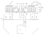
도 5는 본 발명의 다른 실시예에 따른 폐열원 전력생산 시스템의 개략적인 구성도이고, 도 6은 도 5의 측면도이며, 도 7은 도 5의 폐열원 전력생산 시스템의 변형 실시예를 나타낸 구성도이다. 도 5 내지 도 7에 있어서, 도 3 내지 도 4와 동일한 참조부호는 동일한 부재를 나타내며 상세한 설명은 생략하기로 한다.5 is a schematic configuration diagram of a waste heat source power production system according to another embodiment of the present invention, Figure 6 is a side view of Figure 5, Figure 7 is a configuration showing a modified embodiment of the waste heat source power production system of FIG. It is also. 5 to 7, the same reference numerals as used in FIGS. 3 to 4 denote the same members, and detailed descriptions thereof will be omitted.
이들 도면을 참조하여 살펴보면, 본 발명의 다른 실시예에 따른 폐열원 전력생산 시스템(200)은, 선박(10)의 엔진(11) 배기가스가 배출되는 펀넬(12, funnel)의 상부에 마련되어 증발기(110)로 열 에너지를 전달하는 열교환기(14)를 포함하며, 콘덴서 유닛(130)이 펀넬 케이싱(16, funnel casing)의 양 측면에 한 쌍이 배치된다.Referring to these drawings, the waste heat source
본 실시예에서는 도 5에서와 같이 선박(10)의 추진용 엔진(11)으로부터 배기가스가 배출되는 펀넬(12, funnel)의 상부에 열교환기(14)를 설치하여 유체를 중간 매체로 하여 배기가스로부터 열량을 흡수한다. 저온의 유체가 열교환기(14)에 유입되어 고온의 유체가 되어 배출되는데 순환수 펌프(15)가 마련되어 유체가 계속 순환될 수 있도록 한다.In this embodiment, as shown in FIG. 5, a
선박(10)에는 일반적으로 추진용 엔진(11)에서 나오는 배기가스를 이용하여 증기를 생성하는 이코노마이저(13, Economizer)가 설치되어 있다. 하지만 이코노마이저(13)를 통과한 배기가스의 온도는 약 200℃ 정도로 여전히 추가적인 폐열 회수의 목적이 될 수 있다.The
또한, 도 5에서와 같이 펀넬 케이싱(16, funnel casing)의 내부에 증발기(110)와, 터빈(120)과, 공급 펌프(140)를 마련하고, 펀넬 케이싱(16)의 외부 양 측부에 콘덴서 유닛(130)을 증발기(110)와 공급 펌프(140)에 연결되도록 마련하여 각각 배치한다. 펀넬 케이싱(16)의 양 측부에 콘덴서 유닛(130)을 마련하기 위하여 콘덴서 유닛(130)의 하부에서 콘덴서 유닛(130)을 지지하는 지지부(150)가 마련된다.In addition, as shown in FIG. 5, an
증발기(110)와, 터빈(120)과, 공급 펌프(140)를 펀넬 케이싱(16, funnel casing)의 내부에 마련함으로써, 유지보수를 용이하게 하고 증발기(110)의 고온을 유지시켜 열효율을 향상시키며 열교환기(14)와 증발기(110)가 인접하여 배치됨으로써 조밀한 시스템을 구성할 수 있다.By providing the
또한, 선박(10)의 적재 화물(20)과 간섭을 일으키지 않는 높은 곳에 콘덴서 유닛(130)을 마련함으로써 콘덴서 유닛(130)의 공기 및 냉각수 접촉 면적을 증대시켜서 냉각 효과를 향상시킬 수 있으며, 부피가 가장 큰 콘덴서 유닛(130)을 선박(10) 외부의 공간에 배치함으로써 선박(10) 내부에 배치 공간 협소로 인한 설치 곤란을 해결할 수 있다. 도 6을 참조하면, 콘덴서 유닛(130)이 적재 화물(20)보다 높은 부위에 마련됨으로써 공기 유입이 자연스럽게 이루어지며, 설치 공간 협소성 문제를 해결할 수 있음을 알 수 있다.In addition, by providing the
본 실시예에서는, 콘덴서 유닛(130)을 펀넬 케이싱(16)의 양 측부에 한 쌍으로 마련하여 콘덴서 유닛(130)에 의한 냉각 효과를 증대시키고, 또한 선박(10)의 균형성을 향상시켰으나, 이와 달리 경우에 따라서는 콘덴서 유닛(130)이 한쪽에만 배치되어도 무방하다.In this embodiment, the
또한 본 실시예에서는, 하나의 랭킨 사이클을 적용하여 하나의 터빈(120)을 작동시켰으나, 배기가스의 온도가 충분히 큰 경우에는 도 7과 같이 2대의 터빈(120)이 구동되도록 2개의 사이클을 구성할 수도 있다.In addition, in the present embodiment, one
이와 같이, 본 실시예의 폐열원 전력생산 시스템(200)에 의하면, 펀넬(12)의 상부에 열교환기(14)를 설치하여 추가적인 폐열을 회수할 수 있고, 펀넬 케이싱(16) 내부에 증발기(110)와, 터빈(120)과, 공급 펌프(140)를 설치함으로써 유지보수가 용이하고 조밀한 시스템을 구성할 수 있으며, 콘덴서 유닛(130)을 펀넬 케이싱(16) 외부의 양 측부에 마련함으로써 설치 공간의 확보와 냉각 효율을 향상시키는 효과가 있다.As described above, according to the waste heat source
이와 같이 본 발명은 기재된 실시 예에 한정되는 것이 아니고, 본 발명의 사상 및 범위를 벗어나지 않고 다양하게 수정 및 변형할 수 있음은 이 기술의 분야에서 통상의 지식을 가진 자에게 자명하다. 따라서 그러한 수정 예 또는 변형 예들은 본 발명의 특허청구범위에 속한다 하여야 할 것이다.It will be apparent to those skilled in the art that various modifications and variations can be made in the present invention without departing from the spirit or scope of the invention. Accordingly, such modifications or variations are intended to fall within the scope of the appended claims.
10 : 선박11 : 엔진
12 : 펀넬13 : 이코노마이저
14 : 열교환기15 : 순환수 펌프
16 : 펀넬 케이싱20 : 화물
100 : 폐열원 전력생산 시스템110 : 증발기
120 : 터빈121 : 발전기
130 : 콘덴서 유닛131 : 유입 매니폴드
132 : 응축액탱크133 : 핀 튜브
134 : 냉각수 공급 유닛134a : 공급부
134b : 분무부140 : 공급 펌프10 ship 11: engine
12: Funnel 13: Economizer
14
16: funnel casing 20: cargo
100: waste heat power generation system 110: evaporator
120: turbine 121: generator
130: condenser unit 131: inlet manifold
132: condensate tank 133: fin tube
134: cooling
134b: spray section 140: feed pump
Claims (11)
Translated fromKorean상기 증발기와 연결되며 발전기와 결합된 터빈;
상기 터빈과 연결되며 상기 작동유체를 응축시키는 콘덴서 유닛; 및
상기 콘덴서 유닛과 연결되며 상기 작동유체를 상기 증발기로 공급하는 공급 펌프를 포함하며,
상기 콘덴서 유닛은,
상기 선박의 외부에 마련되어 공기 냉각에 의하여 상기 작동유체를 응축시키는 것을 특징으로 하는 폐열원 전력생산 시스템.An evaporator that receives energy from the ship's waste heat source and evaporates the working fluid;
A turbine connected to the evaporator and coupled to a generator;
A condenser unit connected to the turbine and condensing the working fluid; And
A feed pump connected to the condenser unit and supplying the working fluid to the evaporator,
The condenser unit,
Waste heat source power production system characterized in that provided on the outside of the ship to condense the working fluid by air cooling.
상기 콘덴서 유닛은,
상기 터빈을 통과한 상기 작동유체가 유입되는 유입 매니폴드;
상기 유입 매니폴드의 하방에 마련되어 상기 작동유체가 응축되어 저장되는 응축액탱크; 및
상기 유입 매니폴드와 상기 응축액탱크를 연결하도록 마련되며, 상기 작동유체를 냉각시키는 적어도 하나의 핀 튜브(tube)를 포함하는 폐열원 전력생산 시스템.The method of claim 1,
The condenser unit,
An inlet manifold through which the working fluid passing through the turbine flows;
A condensate tank provided under the inlet manifold to condense and store the working fluid; And
And at least one fin tube provided to connect the inlet manifold and the condensate tank to cool the working fluid.
상기 핀 튜브는, 상기 핀 튜브의 외측면에 방사상으로 연장된 복수개의 냉각 핀(fin)을 포함하는 폐열원 전력생산 시스템.The method of claim 2,
And the fin tube includes a plurality of cooling fins extending radially on an outer surface of the fin tube.
상기 콘덴서 유닛은,
상기 핀 튜브의 전방에 마련되어 선박 공조시스템(AHU)의 가습기로부터 드레인(drain)되는 유체를 분무하는 냉각수 공급 유닛을 더 포함하는 폐열원 전력생산 시스템.The method of claim 2,
The condenser unit,
And a cooling water supply unit provided in front of the fin tube to spray fluid drained from the humidifier of the vessel air conditioning system (AHU).
상기 냉각수 공급 유닛은,
상기 선박 공조시스템의 가습기로부터 드레인되는 유체를 공급하는 공급부; 및
상기 핀 튜브의 전방에 마련되어 상기 공급부로부터 공급된 유체를 분무하는 분무부를 포함하는 폐열원 전력생산 시스템.5. The method of claim 4,
The cooling water supply unit,
A supply unit for supplying a fluid drained from the humidifier of the ship air conditioning system; And
A waste heat source power generation system comprising a spraying portion provided in front of the fin tube to spray the fluid supplied from the supply.
상기 증발기, 상기 터빈, 상기 공급 펌프는 하나의 모듈로 마련되는 것을 특징으로 하는 폐열원 전력생산 시스템.The method according to any one of claims 1 to 5,
The evaporator, the turbine, the feed pump is a waste heat source power production system, characterized in that provided as a module.
선박의 엔진 배기가스가 배출되는 펀넬(funnel)의 상부에 마련되어 상기 증발기로 열 에너지를 전달하는 열교환기를 더 포함하는 폐열원 전력생산 시스템.The method of claim 1,
Waste heat source power production system further comprises a heat exchanger provided on top of the funnel (funnel) through which the engine exhaust gas of the ship is discharged to transfer heat energy to the evaporator.
상기 증발기, 상기 터빈, 상기 공급 펌프는 상기 열교환기와 인접하여 펀넬 케이싱(funnel casing)의 내부에 마련되는 것을 특징으로 하는 폐열원 전력생산 시스템.The method of claim 7, wherein
And the evaporator, the turbine and the feed pump are arranged inside a funnel casing adjacent to the heat exchanger.
상기 콘덴서 유닛은 펀넬 케이싱(funnel casing)의 양쪽 외측부에 한 쌍이 배치되는 것을 특징으로 하는 폐열원 전력생산 시스템.9. The method of claim 8,
The condenser unit is a waste heat source power generation system, characterized in that a pair is disposed on both outer sides of the funnel casing (funnel casing).
상기 콘덴서 유닛은,
상기 터빈을 통과한 상기 작동유체가 유입되는 유입 매니폴드;
상기 유입 매니폴드의 하방에 마련되어 상기 작동유체가 응축되어 저장되는 응축액탱크;
상기 유입 매니폴드와 상기 응축액탱크를 연결하도록 마련되며, 상기 작동유체를 냉각시키는 적어도 하나의 핀 튜브(fin-tube); 및
상기 핀 튜브의 전방에 마련되어 선박 공조시스템(AHU)의 가습기로부터 드레인(drain)되는 유체를 분무하는 냉각수 공급 유닛을 포함하는 폐열원 전력생산 시스템.10. The method according to any one of claims 7 to 9,
The condenser unit,
An inlet manifold through which the working fluid passing through the turbine flows;
A condensate tank provided under the inlet manifold to condense and store the working fluid;
At least one fin tube provided to connect the inlet manifold and the condensate tank to cool the working fluid; And
And a cooling water supply unit provided in front of the fin tube to spray fluid drained from the humidifier of the vessel air conditioning system (AHU).
상기 콘덴서 유닛은, 선박에 적재된 적재화물보다 높은 위치에 마련되는 것을 특징으로 하는 폐열원 전력생산 시스템.The method of claim 1,
The condenser unit is a waste heat source power production system, characterized in that provided in a position higher than the load cargo loaded on the vessel.
Priority Applications (1)
| Application Number | Priority Date | Filing Date | Title |
|---|---|---|---|
| KR1020110046584AKR101280520B1 (en) | 2011-05-18 | 2011-05-18 | Power Generation System Using Waste Heat |
Applications Claiming Priority (1)
| Application Number | Priority Date | Filing Date | Title |
|---|---|---|---|
| KR1020110046584AKR101280520B1 (en) | 2011-05-18 | 2011-05-18 | Power Generation System Using Waste Heat |
Publications (2)
| Publication Number | Publication Date |
|---|---|
| KR20120128755A KR20120128755A (en) | 2012-11-28 |
| KR101280520B1true KR101280520B1 (en) | 2013-07-01 |
Family
ID=47513352
Family Applications (1)
| Application Number | Title | Priority Date | Filing Date |
|---|---|---|---|
| KR1020110046584AExpired - Fee RelatedKR101280520B1 (en) | 2011-05-18 | 2011-05-18 | Power Generation System Using Waste Heat |
Country Status (1)
| Country | Link |
|---|---|
| KR (1) | KR101280520B1 (en) |
Families Citing this family (22)
| Publication number | Priority date | Publication date | Assignee | Title |
|---|---|---|---|---|
| WO2010121255A1 (en) | 2009-04-17 | 2010-10-21 | Echogen Power Systems | System and method for managing thermal issues in gas turbine engines |
| CN102575532B (en) | 2009-06-22 | 2015-03-18 | 艾克竣电力系统股份有限公司 | Systems and methods for temperature regulation of inlet gas |
| US9316404B2 (en) | 2009-08-04 | 2016-04-19 | Echogen Power Systems, Llc | Heat pump with integral solar collector |
| US8613195B2 (en) | 2009-09-17 | 2013-12-24 | Echogen Power Systems, Llc | Heat engine and heat to electricity systems and methods with working fluid mass management control |
| US8794002B2 (en) | 2009-09-17 | 2014-08-05 | Echogen Power Systems | Thermal energy conversion method |
| US8869531B2 (en) | 2009-09-17 | 2014-10-28 | Echogen Power Systems, Llc | Heat engines with cascade cycles |
| US8813497B2 (en) | 2009-09-17 | 2014-08-26 | Echogen Power Systems, Llc | Automated mass management control |
| US8616001B2 (en) | 2010-11-29 | 2013-12-31 | Echogen Power Systems, Llc | Driven starter pump and start sequence |
| US8783034B2 (en) | 2011-11-07 | 2014-07-22 | Echogen Power Systems, Llc | Hot day cycle |
| US8857186B2 (en) | 2010-11-29 | 2014-10-14 | Echogen Power Systems, L.L.C. | Heat engine cycles for high ambient conditions |
| WO2013055391A1 (en) | 2011-10-03 | 2013-04-18 | Echogen Power Systems, Llc | Carbon dioxide refrigeration cycle |
| US9091278B2 (en) | 2012-08-20 | 2015-07-28 | Echogen Power Systems, Llc | Supercritical working fluid circuit with a turbo pump and a start pump in series configuration |
| US9341084B2 (en) | 2012-10-12 | 2016-05-17 | Echogen Power Systems, Llc | Supercritical carbon dioxide power cycle for waste heat recovery |
| US9118226B2 (en) | 2012-10-12 | 2015-08-25 | Echogen Power Systems, Llc | Heat engine system with a supercritical working fluid and processes thereof |
| WO2014117068A1 (en) | 2013-01-28 | 2014-07-31 | Echogen Power Systems, L.L.C. | Methods for reducing wear on components of a heat engine system at startup |
| WO2014117074A1 (en) | 2013-01-28 | 2014-07-31 | Echogen Power Systems, L.L.C. | Process for controlling a power turbine throttle valve during a supercritical carbon dioxide rankine cycle |
| JP2016519731A (en) | 2013-03-04 | 2016-07-07 | エコージェン パワー システムズ エル.エル.シー.Echogen Power Systems, L.L.C. | Heat engine system with high net power supercritical carbon dioxide circuit |
| US10570777B2 (en) | 2014-11-03 | 2020-02-25 | Echogen Power Systems, Llc | Active thrust management of a turbopump within a supercritical working fluid circuit in a heat engine system |
| US10883388B2 (en) | 2018-06-27 | 2021-01-05 | Echogen Power Systems Llc | Systems and methods for generating electricity via a pumped thermal energy storage system |
| US11435120B2 (en) | 2020-05-05 | 2022-09-06 | Echogen Power Systems (Delaware), Inc. | Split expansion heat pump cycle |
| CA3201373A1 (en) | 2020-12-09 | 2022-06-16 | Timothy Held | Three reservoir electric thermal energy storage system |
| WO2025010090A1 (en) | 2023-02-07 | 2025-01-09 | Supercritical Storage Company, Inc. | Waste heat integration into pumped thermal energy storage |
Citations (1)
| Publication number | Priority date | Publication date | Assignee | Title |
|---|---|---|---|---|
| KR20100035196A (en)* | 2008-09-26 | 2010-04-05 | 현대중공업 주식회사 | Additional steam generator and steam superheater using hot cooling water from marine engines for power generation utilizing ship waste heat |
- 2011
- 2011-05-18KRKR1020110046584Apatent/KR101280520B1/ennot_activeExpired - Fee Related
Patent Citations (1)
| Publication number | Priority date | Publication date | Assignee | Title |
|---|---|---|---|---|
| KR20100035196A (en)* | 2008-09-26 | 2010-04-05 | 현대중공업 주식회사 | Additional steam generator and steam superheater using hot cooling water from marine engines for power generation utilizing ship waste heat |
Also Published As
| Publication number | Publication date |
|---|---|
| KR20120128755A (en) | 2012-11-28 |
Similar Documents
| Publication | Publication Date | Title |
|---|---|---|
| KR101280520B1 (en) | Power Generation System Using Waste Heat | |
| US9057288B2 (en) | Process utilizing high performance air-cooled combined cycle power plant with dual working fluid bottoming cycle and integrated capacity control | |
| US20090120618A1 (en) | Cooling apparatus for a computer system | |
| CN104864732A (en) | Evaporation type condenser system used for thermal power plant small steam turbine steam exhaust condensing | |
| CN109827270A (en) | An air conditioning system for evaporative cooling lithium bromide absorption refrigeration | |
| CN102809144B (en) | Device and method for using two-stage jet absorption heat pump to improve thermal cycle efficiency | |
| CN211524915U (en) | ORC power generation system employing ORC condensate liquid to cool power generation inverter | |
| KR101499810B1 (en) | Hybrid type condenser system | |
| KR101247772B1 (en) | generator of ship using the organic rankine cycle | |
| JP2007107814A (en) | Air-cooled condenser | |
| JP2008286022A (en) | Engine cooling system | |
| CN222027038U (en) | Energy-saving heat supply system for thermal power plant | |
| CN202522095U (en) | Energy-saving cooling system for reducing exhaust steam pressure of air cooled unit of power plant | |
| CN109386330A (en) | A kind of Organic Rankine Cycle power generator | |
| CN204694095U (en) | For the evaporative condenser system of thermal power plant's small turbine exhaust steam condensation | |
| CN206016979U (en) | Seawater cooling, the efficient combustion engine inlet gas cooling device of mixing low-temperature receiver | |
| KR101336788B1 (en) | A cooling system of the organic rankine cycle | |
| US20170314423A1 (en) | Combined cycle power plant with absorption refrigeration system | |
| CN110735681A (en) | Organic Rankine cycle power generation system adopting organic Rankine cycle condensed liquid to cool power generation inverter | |
| CN102650218A (en) | Turbine generator matched with evaporative hydrogen cooling system | |
| KR200456118Y1 (en) | Energy saving ship with power generation system using orc | |
| JP6666148B2 (en) | Electrical installation having a cooled fuel cell with an absorption heat engine | |
| CN207751198U (en) | Integrated strip heat source type heated type refrigeration unit | |
| CN111023617A (en) | Device and method for cooling dead steam cooling water based on refrigeration mode | |
| KR20210098153A (en) | Hybrid type condenser system |
Legal Events
| Date | Code | Title | Description |
|---|---|---|---|
| A201 | Request for examination | ||
| PA0109 | Patent application | St.27 status event code:A-0-1-A10-A12-nap-PA0109 | |
| PA0201 | Request for examination | St.27 status event code:A-1-2-D10-D11-exm-PA0201 | |
| PN2301 | Change of applicant | St.27 status event code:A-3-3-R10-R13-asn-PN2301 St.27 status event code:A-3-3-R10-R11-asn-PN2301 | |
| PN2301 | Change of applicant | St.27 status event code:A-3-3-R10-R13-asn-PN2301 St.27 status event code:A-3-3-R10-R11-asn-PN2301 | |
| E902 | Notification of reason for refusal | ||
| PE0902 | Notice of grounds for rejection | St.27 status event code:A-1-2-D10-D21-exm-PE0902 | |
| PG1501 | Laying open of application | St.27 status event code:A-1-1-Q10-Q12-nap-PG1501 | |
| P11-X000 | Amendment of application requested | St.27 status event code:A-2-2-P10-P11-nap-X000 | |
| P13-X000 | Application amended | St.27 status event code:A-2-2-P10-P13-nap-X000 | |
| R18-X000 | Changes to party contact information recorded | St.27 status event code:A-3-3-R10-R18-oth-X000 | |
| E701 | Decision to grant or registration of patent right | ||
| PE0701 | Decision of registration | St.27 status event code:A-1-2-D10-D22-exm-PE0701 | |
| R18-X000 | Changes to party contact information recorded | St.27 status event code:A-3-3-R10-R18-oth-X000 | |
| GRNT | Written decision to grant | ||
| PR0701 | Registration of establishment | St.27 status event code:A-2-4-F10-F11-exm-PR0701 | |
| PR1002 | Payment of registration fee | St.27 status event code:A-2-2-U10-U11-oth-PR1002 Fee payment year number:1 | |
| PG1601 | Publication of registration | St.27 status event code:A-4-4-Q10-Q13-nap-PG1601 | |
| R18-X000 | Changes to party contact information recorded | St.27 status event code:A-5-5-R10-R18-oth-X000 | |
| PN2301 | Change of applicant | St.27 status event code:A-5-5-R10-R13-asn-PN2301 St.27 status event code:A-5-5-R10-R11-asn-PN2301 | |
| R18-X000 | Changes to party contact information recorded | St.27 status event code:A-5-5-R10-R18-oth-X000 | |
| PR1001 | Payment of annual fee | St.27 status event code:A-4-4-U10-U11-oth-PR1001 Fee payment year number:4 | |
| PR1001 | Payment of annual fee | St.27 status event code:A-4-4-U10-U11-oth-PR1001 Fee payment year number:5 | |
| FPAY | Annual fee payment | Payment date:20180601 Year of fee payment:6 | |
| PR1001 | Payment of annual fee | St.27 status event code:A-4-4-U10-U11-oth-PR1001 Fee payment year number:6 | |
| P22-X000 | Classification modified | St.27 status event code:A-4-4-P10-P22-nap-X000 | |
| PR1001 | Payment of annual fee | St.27 status event code:A-4-4-U10-U11-oth-PR1001 Fee payment year number:7 | |
| PR1001 | Payment of annual fee | St.27 status event code:A-4-4-U10-U11-oth-PR1001 Fee payment year number:8 | |
| PN2301 | Change of applicant | St.27 status event code:A-5-5-R10-R13-asn-PN2301 St.27 status event code:A-5-5-R10-R11-asn-PN2301 | |
| PC1903 | Unpaid annual fee | St.27 status event code:A-4-4-U10-U13-oth-PC1903 Not in force date:20210626 Payment event data comment text:Termination Category : DEFAULT_OF_REGISTRATION_FEE | |
| PC1903 | Unpaid annual fee | St.27 status event code:N-4-6-H10-H13-oth-PC1903 Ip right cessation event data comment text:Termination Category : DEFAULT_OF_REGISTRATION_FEE Not in force date:20210626 |